EP2418770A1 - Automatic gain control - Google Patents
Automatic gain control Download PDFInfo
- Publication number
- EP2418770A1 EP2418770A1 EP10171264A EP10171264A EP2418770A1 EP 2418770 A1 EP2418770 A1 EP 2418770A1 EP 10171264 A EP10171264 A EP 10171264A EP 10171264 A EP10171264 A EP 10171264A EP 2418770 A1 EP2418770 A1 EP 2418770A1
- Authority
- EP
- European Patent Office
- Prior art keywords
- amplifier
- gain control
- signal
- value
- gain
- Prior art date
- Legal status (The legal status is an assumption and is not a legal conclusion. Google has not performed a legal analysis and makes no representation as to the accuracy of the status listed.)
- Withdrawn
Links
Images

Classifications
-
- H—ELECTRICITY
- H03—ELECTRONIC CIRCUITRY
- H03G—CONTROL OF AMPLIFICATION
- H03G7/00—Volume compression or expansion in amplifiers
- H03G7/06—Volume compression or expansion in amplifiers having semiconductor devices
-
- H—ELECTRICITY
- H03—ELECTRONIC CIRCUITRY
- H03G—CONTROL OF AMPLIFICATION
- H03G3/00—Gain control in amplifiers or frequency changers
- H03G3/001—Digital control of analog signals
-
- H—ELECTRICITY
- H03—ELECTRONIC CIRCUITRY
- H03G—CONTROL OF AMPLIFICATION
- H03G3/00—Gain control in amplifiers or frequency changers
- H03G3/20—Automatic control
- H03G3/30—Automatic control in amplifiers having semiconductor devices
- H03G3/3005—Automatic control in amplifiers having semiconductor devices in amplifiers suitable for low-frequencies, e.g. audio amplifiers
Definitions
- This invention relates to an automatic gain controller and to a method of automatic gain control for an amplifier.
- AGC automatic gain control
- AGC also finds use in other applications where it is desired to compress the dynamic range of a signal for transmission over a band-limited channel.
- AGC has the advantage over coding a signal (for example, using orthogonal frequency division multiplexing or similar techniques) that despite the fact that the coded signal can carry more information in a given time period, a signal can be compressed by AGC in real time (i.e. without introducing a delay) and bears a strong correlation to the original signal.
- the subjective quality of the signal is high, and it can be used as the source of audio output, for example.
- An automatic gain controller will be designed to vary an amplifier's gain in response to a predefined condition (for example, gain may be limited in response to the average output signal exceeding a threshold).
- the AGC response is defined by two time constants: the attack time and the release time.
- the attack time determines how quickly the AGC responds to a high average output signal level by reducing the amplifier's gain.
- the release time determines how quickly the AGC allows the gain to recover to its nominal level once a transient high average output signal level has passed. Different values of these constants will be appropriate for different signal types, such as speech and music.
- the decrease in gain during the attack phase is a trade-off between fast response (i.e. a quick attack) and audibility, the attack becoming more audible as the response time shortens.
- a fast drop in gain is acceptable for some signals, whereas for others it is not.
- attack and release time constants need to be set in the design of the automatic gain controller and cannot easily be adjusted. This makes it difficult to produce an AGC that can be used with different types of signal.
- US5,912,977 discloses an AGC for use in a hearing aid that has a decay time constant switchable between two values depending on the amplitude of an amplifier's output.
- this is limited to a long time constant to reduce total harmonic distortion introduced by the AGC when the signal level is high and a short time constant when the signal level is low, which is required so that the amplifier of the hearing aid recovers quickly to a high value to amplify the low level signals sufficiently.
- an automatic gain controller comprising an input for monitoring a signal associated with an amplifier and a gain control circuit for controlling the gain of the amplifier in response to the monitored signal, wherein the gain control circuit is adapted to control the gain of the amplifier in accordance with a gain control function having continuously variable attack and release time constants, both of which depend on the amplitude of the monitored signal.
- the invention provides a way by which the release time constant can adjust to suit the signal being amplified.
- a shorter time constant can be used with low amplitude signals, and a longer time constant with high amplitude signals.
- the attack time also adapts to the signal level. The problems discussed above relating to inappropriate attack and release time constants are therefore overcome, leading to a reduction in audible artefacts.
- the signal associated with the amplifier will typically be its input or its output.
- the monitored signal is an output signal from the amplifier and the gain control function is equal to: A ( n -1) ⁇ ⁇ M ( q ), where A(n-1) is a previous value of the gain of the amplifier, ⁇ is a constant and M(q) is a gain control factor that depends on the amplitude of the monitored signal and provides the continuously variable attack and release time constants.
- the monitored signal is an input signal to the amplifier and the gain control function is equal to: 1 A ⁇ n - 1 ⁇ ⁇ M q , where A(n-1) is a previous value of the gain of the amplifier, ⁇ is a constant and M(q) is a gain control factor that depends on the amplitude of the monitored signal and provides the continuously variable attack and release time constants.
- ⁇ will have a value in the range of 0.99 to 0.9999.
- the AGC of the second embodiment is able to reverse the effects of the AGC of the first embodiment.
- an original signal amplified by an amplifier controlled by an AGC according to the first embodiment can be recovered by passing it through a second amplifier controlled by an AGC according to the second embodiment. Therefore, a signal can be compressed to have a lower dynamic range for transmission over a band-limited channel and then recovered using the transmitted signal alone. This allows the original signal to be recovered without transmitting any additional data to enable this so that post-processing techniques such as echo cancellation can be used.
- the amplifiers should preferably be identical.
- a system comprising a first AGC according to the first embodiment for controlling the gain of a first amplifier, the input of the first AGC being coupled to the output of the first amplifier; a second AGC according to the second embodiment for controlling the gain of a second amplifier, the input of the second AGC being coupled to the input of the second amplifier; and a transmission channel coupling the output of the first amplifier to the input of the second amplifier, wherein the first and second amplifiers are substantially identical.
- the combination of the first and second embodiments in this way provides a system in which differences between the gain control functions of the two embodiments is relatively unimportant, provided that the amplifiers are sufficiently similar and the gain control factors have a value near unity when no signal is being amplified. This results in a system where the differences in the two gain control functions only become apparent when the AGC is actively adjusting the gain. This will add total harmonic distortion or noise to the signal, but it will typically be much less than if the original signal were distorted by the band-limited channel or the AGC of the first embodiment was not reversed by the AGC of the second embodiment.
- the gain control factor has a value of 1 in a mid-scale region in which the monitored signal has an amplitude between first and second predefined values and monotonically decreases towards a value of zero in lower and upper scale regions in which the monitored signal has an amplitude between negative full scale and the first predefined value and between the second predefined value and positive full scale respectively.
- the value of the exponent, 15, is just a typical value. Other values could also be used instead, typically lying in a range of 1 to 50. Indeed, other functions leading to a similar shape for M(q) when plotted against q can be used. The exact shape can be selected based on the specific characteristics of the signal to be processed.
- the gain control factor may have a value of 1 in a mid-scale region in which the monitored signal has an amplitude between first and second predefined values and a value lower than 1 in lower and upper scale regions in which the monitored signal has an amplitude between negative full scale and the first predefined value and between the second predefined value and positive full scale respectively.
- the AGC may further comprise a memory addressable using an address value based on the monitored signal to retrieve a corresponding value of the gain control factor.
- a method of automatic gain control for an amplifier comprising monitoring a signal associated with an amplifier, and controlling the gain of the amplifier in response to the monitored signal, in accordance with a gain control function having continuously variable attack and release time constants, both of which depend on the amplitude of the monitored signal.
- the monitored signal is an output signal from the amplifier (1) and the gain control function is equal to: A ( n -1) ⁇ ⁇ M ( q ), where A(n-1) is a previous value of the gain of the amplifier (1), ⁇ is a constant and M(q) is a gain control factor that depends on the amplitude of the monitored signal and provides the continuously variable attack and release time constants.
- the monitored signal is an input signal to the amplifier (1) and the gain control function is equal to: 1 A ⁇ n - 1 ⁇ ⁇ M q , where A(n-1) is a previous value of the gain of the amplifier (4), ⁇ is a constant and M(q) is a gain control factor that depends on the amplitude of the monitored signal and provides the continuously variable attack and release time constants.
- the method of automatic gain control of the second embodiment is able to reverse the effects of the method of automatic gain control of the first embodiment.
- first and second embodiments of the second aspect can be advantageously combined (as with the first and second embodiments of the first aspect) to form a method in which differences between the gain control functions of the two embodiments is relatively unimportant, provided that the amplifiers are sufficiently similar and the gain control factors have a value near unity when no signal is being amplified.
- the amplifiers should preferably be identical.
- a method of transmitting a signal over a transmission channel comprising controlling the gain of a first amplifier using a method according to the first embodiment, the monitored signal being the output signal of the first amplifier; transmitting the output signal from the first amplifier over the transmission channel; receiving the transmitted signal from the transmission channel at the input of a second amplifier; and controlling the gain of the second amplifier using a method according to the second embodiment, the monitored signal being the input signal to the second amplifier.
- the gain control factor has a value of 1 in a mid-scale region in which the monitored signal has an amplitude between first and second predefined values and monotonically decreases towards a value of zero in lower and upper scale regions in which the monitored signal has an amplitude between negative full scale and the first predefined value and between the second predefined value and positive full scale respectively.
- the gain control factor has a value of 1 in a mid-scale region in which the monitored signal has an amplitude between first and second predefined values and a value lower than 1 in lower and upper scale regions in which the monitored signal has an amplitude between negative full scale and the first predefined value and between the second predefined value and positive full scale respectively.
- the previous value of the amplifier's gain referred to above with respect to the first and second aspects of the invention could be a value at a predefined preceding time. If the AGC operates at discrete time intervals as will typically be the case, the previous value could be represented by an immediately preceding sample value.
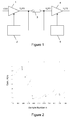
- Figure 1 shows a first variable gain amplifier 1, the gain of which is controlled by an automatic gain controller (AGC) 2.
- the amplifier 1 receives at its input a signal voltage v i (n) and produces an output signal voltage v o (n).
- the AGC 2 controls the gain of amplifier 1 via a gain control input on amplifier 1 in accordance with the following gain control function: A ⁇ n - 1 ⁇ ⁇ M q where:
- Figure 2 shows how the gain, A(n), of amplifier 1 might vary over time (represented by sample number) when under the control of AGC 2.
- the gain A(n) is expressed as a normalised value so that a value of 1 indicates the full gain available. It can be seen how the gain changes at different rates as the values of the attack and release time constants vary with the signal. For example, the release time constant is clearly lower between samples 2500 and 3500 than it is between samples 4500 and 6300.
- the AGC 2 operates at discrete time intervals, with n representing the current time interval.
- the AGC 2 will include sample-and-hold circuitry or an addressable memory to hold the value of gain, A, at the preceding time interval (n-1).
- the AGC 2 controls the gain of amplifier 1 by monitoring the output voltage, v o (n), and varying the voltage on the gain control input in accordance with the above gain control function. Effectively, the AGC 2 varies the gain depending on the current value of the output voltage, v o (n).
- the AGC 2 comprises circuitry, which generates values for A(n-1 ) ⁇ and M(q).
- the gain control factor M(q) depends on the value of the signal monitored by the AGC 2, in this case output voltage v o (n).
- the values of M(q) could be stored in a memory, which is addressable using an address value based on the monitored signal to retrieve a corresponding value of the gain control factor.
- M(q) there are many possible transfer functions that could be used as the gain control factor, M(q).
- the particular transfer function chosen will depend on the characteristics of the signal being amplified and the desired compression of the dynamic range.
- One example could be implemented using a simple digital switch, which sets M(q) to one value if the output voltage v o (n) is below a threshold and to a different value (to reduce the gain of amplifier 1) if the output voltage v o (n) is equal to or greater than the threshold.
- FIG. 3a An example of such a thresholding function is shown in Figure 3a .
- the value of M(q) is equal to 1 (or very nearly 1) when the output voltage v o (n) (i.e. the input to AGC 2) is in a mid-scale region.
- the value of M(q) becomes 0.9 (or very nearly 0.9).
- the value of M(q) that is chosen for the negative and positive full-scale regions (0.9 in this case) will depend on the desired degree of compression required and on the expected signal characteristics.
- Figure 3b shows another example transfer function.
- the value of M(q) is equal to 1 (or very nearly 1) when the output voltage v o (n) (i.e. the input to AGC 2) is in a mid-scale region.
- the value of M(q) monotonically decreases towards 0. This provides a gradual decrease in gain as the output voltage signal reaches high values in either a positive or negative direction.
- M q 1 - abs q 15 , where q is the magnitude of the monitored signal, normalised to fall within a range of -1 to +1.
- AGC 5 controls the gain of amplifier 4 via a gain control input on amplifier 4 in accordance with the following gain control function: 1 A ⁇ n - 1 ⁇ ⁇ M q
- amplifier 4 and AGC 5 in combination can recover the original signal from the output signal from amplifier 1 alone.
- the amplifiers 1 and 4 should preferably be identical.
- the resultant output signal from amplifier 4 can be used in post-processing techniques such as noise and echo cancellation.
- the values of the reciprocal of M(q) for each value of signal level can be calculated in advance and stored in a memory.
- the appropriate value of M(q) can then be retrieved when required by addressing the memory depending on the value of signal level.
- the AGC 5 comprises circuitry, which generates or looks up values for the reciprocal A(n-1) ⁇ and multiplies this by the reciprocal of M(q) to determine the gain control function.
- the value of M(q) determines the attack and release time constants of the AGC algorithm. This is best understood by way of example. If, for example, the input signal level to amplifer 1 increases to a high value very rapidly (such as a step function input) then using the gain control function of Figure 3a it will take many cycles of operation of the AGC 2 to reach an appropriate value for the gain so that the signal is attenuated as desired. On the other hand, using the gain control function of Figure 3b , the change in gain may take only a few steps to bring about the required attenuation. In each case, the number of steps required to bring about the required attenuation depends on the signal characteristics, such as its level and rate of change. This means that the gain control function M(q) causes the attack time to be signal dependent.
- release time constant will be longer for the gain control function of Figure 3b than it will for that of Figure 3a , although it will typically take many cycles of operation in either case. Again, the exact length of release time depends on the signal characteristics, such as its level and rate of change. This means that the gain control function M(q) causes the release time to be signal dependent.
- any mismatches due for example to differences in AGCs 2 and 5 or bit error failures incurred in the channel 3 are smeared over time and are therefore not particularly audible as they would be without the AGC algorithm presented herein. This is because a bit error or signal error will result in a mismatch of the gain factor applied by AGC 2 to that applied by AGC 5. Since the finite value of release time causes the influence of this mismatch to endure during the release phase, the signal effectively adapts to the error, smoothing it out and making it less audible.
- the shape of the function M(q) determines the entropy of the signal processed by a combination of amplifier 1 and AGC 2, the attack-release behaviour and the robustness against the errors on the channel 3.
Landscapes
- Engineering & Computer Science (AREA)
- Multimedia (AREA)
- Control Of Amplification And Gain Control (AREA)
Abstract
An automatic gain controller (AGC) (2) is disclosed. The AGC comprises an input for monitoring a signal associated with an amplifier (1; 4) and a gain control circuit for controlling the gain of the amplifier (1; 4) in response to the monitored signal, wherein the gain control circuit is adapted to control the gain of the amplifier (1; 4) in accordance with a gain control function having continuously variable attack and release time constants, both of which depend on the amplitude of the monitored signal.
Description
- This invention relates to an automatic gain controller and to a method of automatic gain control for an amplifier.
- A traditional use of automatic gain control (AGC) is in an AM radio receiver. Here, AGC is used to vary the gain of the receiver such that the output signal has an approximately constant value. This allows the receiver to operate relatively independently of the power and distance of the transmitter and to limit the effects of signal fluctuations caused by fading in the signal strength due to environmental factors.
- AGC also finds use in other applications where it is desired to compress the dynamic range of a signal for transmission over a band-limited channel. AGC has the advantage over coding a signal (for example, using orthogonal frequency division multiplexing or similar techniques) that despite the fact that the coded signal can carry more information in a given time period, a signal can be compressed by AGC in real time (i.e. without introducing a delay) and bears a strong correlation to the original signal. Thus, the subjective quality of the signal is high, and it can be used as the source of audio output, for example.
- An automatic gain controller will be designed to vary an amplifier's gain in response to a predefined condition (for example, gain may be limited in response to the average output signal exceeding a threshold). The AGC response is defined by two time constants: the attack time and the release time. The attack time determines how quickly the AGC responds to a high average output signal level by reducing the amplifier's gain. The release time determines how quickly the AGC allows the gain to recover to its nominal level once a transient high average output signal level has passed. Different values of these constants will be appropriate for different signal types, such as speech and music.
- The decrease in gain during the attack phase is a trade-off between fast response (i.e. a quick attack) and audibility, the attack becoming more audible as the response time shortens. A fast drop in gain is acceptable for some signals, whereas for others it is not.
- With respect to the release or decay phase, a long duration can lead to an unacceptable "pumping" effect, whereas an overly short release phase can cause the attack phase to initiate again, leading to the production of idle tones as the AGC cycles between attack and release phases periodically.
- Typically, the attack and release time constants need to be set in the design of the automatic gain controller and cannot easily be adjusted. This makes it difficult to produce an AGC that can be used with different types of signal.
-
US5,912,977 discloses an AGC for use in a hearing aid that has a decay time constant switchable between two values depending on the amplitude of an amplifier's output. However, this is limited to a long time constant to reduce total harmonic distortion introduced by the AGC when the signal level is high and a short time constant when the signal level is low, which is required so that the amplifier of the hearing aid recovers quickly to a high value to amplify the low level signals sufficiently. - Furthermore, other signal processing algorithms such as noise cancellation and echo cancellation do not work well with AGC since they cannot detect the rapid gain changes that have been imposed by the automatic gain controller from the signal alone.
- In accordance with a first aspect of the invention, there is provided an automatic gain controller (AGC) comprising an input for monitoring a signal associated with an amplifier and a gain control circuit for controlling the gain of the amplifier in response to the monitored signal, wherein the gain control circuit is adapted to control the gain of the amplifier in accordance with a gain control function having continuously variable attack and release time constants, both of which depend on the amplitude of the monitored signal.
- Hence, the invention provides a way by which the release time constant can adjust to suit the signal being amplified. Thus, a shorter time constant can be used with low amplitude signals, and a longer time constant with high amplitude signals. Similarly, the attack time also adapts to the signal level. The problems discussed above relating to inappropriate attack and release time constants are therefore overcome, leading to a reduction in audible artefacts.
- The signal associated with the amplifier will typically be its input or its output.
- In a first embodiment, the monitored signal is an output signal from the amplifier and the gain control function is equal to: A(n-1) λ · M(q), where A(n-1) is a previous value of the gain of the amplifier, λ is a constant and M(q) is a gain control factor that depends on the amplitude of the monitored signal and provides the continuously variable attack and release time constants.
- In a second embodiment, the monitored signal is an input signal to the amplifier and the gain control function is equal to:

- Typically, λ will have a value in the range of 0.99 to 0.9999.
- The AGC of the second embodiment is able to reverse the effects of the AGC of the first embodiment. Thus, an original signal amplified by an amplifier controlled by an AGC according to the first embodiment can be recovered by passing it through a second amplifier controlled by an AGC according to the second embodiment. Therefore, a signal can be compressed to have a lower dynamic range for transmission over a band-limited channel and then recovered using the transmitted signal alone. This allows the original signal to be recovered without transmitting any additional data to enable this so that post-processing techniques such as echo cancellation can be used.
- When the first and second embodiments are combined to form a system in this way, the amplifiers should preferably be identical.
- Thus, there may be provided a system comprising a first AGC according to the first embodiment for controlling the gain of a first amplifier, the input of the first AGC being coupled to the output of the first amplifier; a second AGC according to the second embodiment for controlling the gain of a second amplifier, the input of the second AGC being coupled to the input of the second amplifier; and a transmission channel coupling the output of the first amplifier to the input of the second amplifier, wherein the first and second amplifiers are substantially identical.
- The combination of the first and second embodiments in this way provides a system in which differences between the gain control functions of the two embodiments is relatively unimportant, provided that the amplifiers are sufficiently similar and the gain control factors have a value near unity when no signal is being amplified. This results in a system where the differences in the two gain control functions only become apparent when the AGC is actively adjusting the gain. This will add total harmonic distortion or noise to the signal, but it will typically be much less than if the original signal were distorted by the band-limited channel or the AGC of the first embodiment was not reversed by the AGC of the second embodiment.
- In a preferred embodiment, the gain control factor has a value of 1 in a mid-scale region in which the monitored signal has an amplitude between first and second predefined values and monotonically decreases towards a value of zero in lower and upper scale regions in which the monitored signal has an amplitude between negative full scale and the first predefined value and between the second predefined value and positive full scale respectively.
- In this preferred embodiment, the gain control factor may be defined by: M(q)=1-abs(q 15), where q is the magnitude of the monitored signal, normalised to fall within a range of -1 to +1. The value of the exponent, 15, is just a typical value. Other values could also be used instead, typically lying in a range of 1 to 50. Indeed, other functions leading to a similar shape for M(q) when plotted against q can be used. The exact shape can be selected based on the specific characteristics of the signal to be processed.
- In an alternative embodiment, the gain control factor may have a value of 1 in a mid-scale region in which the monitored signal has an amplitude between first and second predefined values and a value lower than 1 in lower and upper scale regions in which the monitored signal has an amplitude between negative full scale and the first predefined value and between the second predefined value and positive full scale respectively.
- The AGC may further comprise a memory addressable using an address value based on the monitored signal to retrieve a corresponding value of the gain control factor.
- In accordance with a second aspect of the invention, there is provided a method of automatic gain control for an amplifier, the method comprising monitoring a signal associated with an amplifier, and controlling the gain of the amplifier in response to the monitored signal, in accordance with a gain control function having continuously variable attack and release time constants, both of which depend on the amplitude of the monitored signal.
- In a first embodiment, the monitored signal is an output signal from the amplifier (1) and the gain control function is equal to: A(n-1)λ · M(q), where A(n-1) is a previous value of the gain of the amplifier (1), λ is a constant and M(q) is a gain control factor that depends on the amplitude of the monitored signal and provides the continuously variable attack and release time constants.
- In a second embodiment, the monitored signal is an input signal to the amplifier (1) and the gain control function is equal to:

- The method of automatic gain control of the second embodiment is able to reverse the effects of the method of automatic gain control of the first embodiment.
- Thus, the first and second embodiments of the second aspect can be advantageously combined (as with the first and second embodiments of the first aspect) to form a method in which differences between the gain control functions of the two embodiments is relatively unimportant, provided that the amplifiers are sufficiently similar and the gain control factors have a value near unity when no signal is being amplified.
- When the first and second embodiments are combined to form a system in this way, the amplifiers should preferably be identical.
- Accordingly, there may be provided a method of transmitting a signal over a transmission channel, the method comprising controlling the gain of a first amplifier using a method according to the first embodiment, the monitored signal being the output signal of the first amplifier; transmitting the output signal from the first amplifier over the transmission channel; receiving the transmitted signal from the transmission channel at the input of a second amplifier; and controlling the gain of the second amplifier using a method according to the second embodiment, the monitored signal being the input signal to the second amplifier.
- In a preferred embodiment, the gain control factor has a value of 1 in a mid-scale region in which the monitored signal has an amplitude between first and second predefined values and monotonically decreases towards a value of zero in lower and upper scale regions in which the monitored signal has an amplitude between negative full scale and the first predefined value and between the second predefined value and positive full scale respectively.
- In this preferred embodiment, the gain control factor may be defined by: M(q) = 1- abs(q 15), where q is the magnitude of the monitored signal, normalised to fall within a range of -1 to +1.
- In another embodiment, the gain control factor has a value of 1 in a mid-scale region in which the monitored signal has an amplitude between first and second predefined values and a value lower than 1 in lower and upper scale regions in which the monitored signal has an amplitude between negative full scale and the first predefined value and between the second predefined value and positive full scale respectively.
- The previous value of the amplifier's gain referred to above with respect to the first and second aspects of the invention could be a value at a predefined preceding time. If the AGC operates at discrete time intervals as will typically be the case, the previous value could be represented by an immediately preceding sample value.
- Examples of the invention will now be described in detail with reference to the accompanying drawings, in which:
-
Figure 1 shows a system applying AGC according to the invention; -
Figure 2 shows an example of how gain might vary when controlled using an AGC according toFigure 1 ; and -
Figures 3a and 3b show graphs of suitable gain control factors. -
Figure 1 shows a firstvariable gain amplifier 1, the gain of which is controlled by an automatic gain controller (AGC) 2. Theamplifier 1 receives at its input a signal voltage vi(n) and produces an output signal voltage vo(n). TheAGC 2 controls the gain ofamplifier 1 via a gain control input onamplifier 1 in accordance with the following gain control function:
where: - A(n-1) is the gain of
amplifier 1 at the immediately preceding discrete time interval; - λ is a constant with a value typically in the range 0.99 to 0.9999; and M(q) is a gain control factor, which depends on signal level q.
-
Figure 2 shows how the gain, A(n), ofamplifier 1 might vary over time (represented by sample number) when under the control ofAGC 2. InFigure 2 , the gain A(n) is expressed as a normalised value so that a value of 1 indicates the full gain available. It can be seen how the gain changes at different rates as the values of the attack and release time constants vary with the signal. For example, the release time constant is clearly lower between samples 2500 and 3500 than it is between samples 4500 and 6300. - In this embodiment, the
AGC 2 operates at discrete time intervals, with n representing the current time interval. Thus, theAGC 2 will include sample-and-hold circuitry or an addressable memory to hold the value of gain, A, at the preceding time interval (n-1). - The
AGC 2 controls the gain ofamplifier 1 by monitoring the output voltage, vo(n), and varying the voltage on the gain control input in accordance with the above gain control function. Effectively, theAGC 2 varies the gain depending on the current value of the output voltage, vo(n). - The
AGC 2 comprises circuitry, which generates values for A(n-1 )λ and M(q). The gain control factor M(q) depends on the value of the signal monitored by theAGC 2, in this case output voltage vo(n). The values of M(q) could be stored in a memory, which is addressable using an address value based on the monitored signal to retrieve a corresponding value of the gain control factor. - There are many possible transfer functions that could be used as the gain control factor, M(q). The particular transfer function chosen will depend on the characteristics of the signal being amplified and the desired compression of the dynamic range. One example could be implemented using a simple digital switch, which sets M(q) to one value if the output voltage vo(n) is below a threshold and to a different value (to reduce the gain of amplifier 1) if the output voltage vo(n) is equal to or greater than the threshold.
- An example of such a thresholding function is shown in
Figure 3a . In this, the value of M(q) is equal to 1 (or very nearly 1) when the output voltage vo(n) (i.e. the input to AGC 2) is in a mid-scale region. However, when the output voltage vo(n) is outside the mid-scale region either in a negative full-scale or a positive full-scale region, the value of M(q) becomes 0.9 (or very nearly 0.9). The value of M(q) that is chosen for the negative and positive full-scale regions (0.9 in this case) will depend on the desired degree of compression required and on the expected signal characteristics. -
Figure 3b shows another example transfer function. In this, the value of M(q) is equal to 1 (or very nearly 1) when the output voltage vo(n) (i.e. the input to AGC 2) is in a mid-scale region. However, as the output voltage vo(n) departs from the mid-scale region either towards a negative full-scale or a positive full-scale region, the value of M(q) monotonically decreases towards 0. This provides a gradual decrease in gain as the output voltage signal reaches high values in either a positive or negative direction. - A suitable equation for calculating M(q) in the example of
Figure 3(b) is:
where q is the magnitude of the monitored signal, normalised to fall within a range of -1 to +1. - In some circumstances it will be desired to reverse the effects of
AGC 2 after transmission overchannel 3, for example if post-processing such as echo or noise cancellation is to be performed on the signal. The combination ofamplifier 4 andAGC 5 does this.AGC 5 is similar toAGC 2, the only difference being that it uses the reciprocal of M(q) as the gain control factor. Thus,AGC 5 controls the gain ofamplifier 4 via a gain control input onamplifier 4 in accordance with the following gain control function:
- Thus,
amplifier 4 andAGC 5 in combination can recover the original signal from the output signal fromamplifier 1 alone. For this purpose, theamplifiers amplifier 4 can be used in post-processing techniques such as noise and echo cancellation. - The values of the reciprocal of M(q) for each value of signal level can be calculated in advance and stored in a memory. The appropriate value of M(q) can then be retrieved when required by addressing the memory depending on the value of signal level.
- The
AGC 5 comprises circuitry, which generates or looks up values for the reciprocal A(n-1)λ and multiplies this by the reciprocal of M(q) to determine the gain control function. - In the above equations, the value of M(q) determines the attack and release time constants of the AGC algorithm. This is best understood by way of example. If, for example, the input signal level to
amplifer 1 increases to a high value very rapidly (such as a step function input) then using the gain control function ofFigure 3a it will take many cycles of operation of theAGC 2 to reach an appropriate value for the gain so that the signal is attenuated as desired. On the other hand, using the gain control function ofFigure 3b , the change in gain may take only a few steps to bring about the required attenuation. In each case, the number of steps required to bring about the required attenuation depends on the signal characteristics, such as its level and rate of change. This means that the gain control function M(q) causes the attack time to be signal dependent. - A similar situation occurs with respect to control of the release time constant. Typically, the release time constant will be longer for the gain control function of
Figure 3b than it will for that ofFigure 3a , although it will typically take many cycles of operation in either case. Again, the exact length of release time depends on the signal characteristics, such as its level and rate of change. This means that the gain control function M(q) causes the release time to be signal dependent. - If the release time is sufficiently short (e.g. a few milliseconds) any mismatches (due for example to differences in
AGCs AGC 2 to that applied byAGC 5. Since the finite value of release time causes the influence of this mismatch to endure during the release phase, the signal effectively adapts to the error, smoothing it out and making it less audible. - The shape of the function M(q) determines the entropy of the signal processed by a combination of
amplifier 1 andAGC 2, the attack-release behaviour and the robustness against the errors on thechannel 3. - Other variations to the disclosed embodiments can be understood and effected by those skilled in the art in practising the claimed invention, from a study of the drawings, the disclosure, and the appended claims. In the claims, the word "comprising" does not exclude other elements or steps, and the indefinite article "a" or "an" does not exclude a plurality. A single processor or other unit may fulfill the functions of several items recited in the claims. The mere fact that certain measures are recited in mutually different dependent claims does not indicate that a combination of these measures cannot be used to advantage. Any reference signs in the claims should not be construed as limiting the scope.
Claims (15)
- An automatic gain controller (AGC) (2) comprising an input for monitoring a signal associated with an amplifier (1; 4) and a gain control circuit for controlling the gain of the amplifier (1; 4) in response to the monitored signal, wherein the gain control circuit is adapted to control the gain of the amplifier (1; 4) in accordance with a gain control function having continuously variable attack and release time constants, both of which depend on the amplitude of the monitored signal.
- An AGC (2) according to claim 1, wherein the monitored signal is an output signal from the amplifier (1) and the gain control function is equal to: A(n-1)λ· M(q), where A(n-1) is a previous value of the gain of the amplifier (1), λ is a constant and M(q) is a gain control factor that depends on the amplitude of the monitored signal and provides the continuously variable attack and release time constants.
- An AGC (5) according to claim 1, wherein the monitored signal is an input signal to the amplifier (1) and the gain control function is equal to:

- An AGC (2; 5) according to claim 2 or claim 3, wherein the gain control factor has a value of 1 in a mid-scale region in which the monitored signal has an amplitude between first and second predefined values and monotonically decreases towards a value of zero in lower and upper scale regions in which the monitored signal has an amplitude between negative full scale and the first predefined value and between the second predefined value and positive full scale respectively.
- An AGC (2; 5) according to claim 4, wherein the gain control factor is defined by: M(q) = 1- abs(q 15), where q is the magnitude of the monitored signal, normalised to fall within a range of -1 to +1.
- An AGC (2; 5) according to claim 2 or claim 3, wherein the gain control factor has a value of 1 in a mid-scale region in which the monitored signal has an amplitude between first and second predefined values and a value lower than 1 in lower and upper scale regions in which the monitored signal has an amplitude between negative full scale and the first predefined value and between the second predefined value and positive full scale respectively.
- An AGC (2; 5) according to any of claims 2 to 6, further comprising a memory addressable using an address value based on the monitored signal to retrieve a corresponding value of the gain control factor.
- A system comprising a first AGC (2) according to claim 2 for controlling the gain of a first amplifier (1), the input of the first AGC being coupled to the output of the first amplifier (1); a second AGC (5) according to claim 3 for controlling the gain of a second amplifier (4), the input of the second AGC being coupled to the input of the second amplifier (4); and a transmission channel (3) coupling the output of the first amplifier (1) to the input of the second amplifier (4), wherein the first and second amplifiers are substantially identical.
- A method of automatic gain control for an amplifier (1; 4), the method comprising monitoring a signal associated with an amplifier (1; 4), and controlling the gain of the amplifier (1; 4) in response to the monitored signal, in accordance with a gain control function having continuously variable attack and release time constants, both of which depend on the amplitude of the monitored signal.
- A method of automatic gain control according to claim 9, wherein the monitored signal is an output signal from the amplifier (1) and the gain control function is equal to: A(n-1) λ · M(q), where A(n-1) is a previous value of the gain of the amplifier (1), λ is a constant and M(q) is a gain control factor that depends on the amplitude of the monitored signal and provides the continuously variable attack and release time constants.
- A method of automatic gain control according to claim 9, wherein the monitored signal is an input signal to the amplifier (1) and the gain control function is equal to:

- A method of automatic gain control according to claim 10 or claim 11, wherein the gain control factor has a value of 1 in a mid-scale region in which the monitored signal has an amplitude between first and second predefined values and monotonically decreases towards a value of zero in lower and upper scale regions in which the monitored signal has an amplitude between negative full scale and the first predefined value and between the second predefined value and positive full scale respectively.
- A method of automatic gain control according to claim 12, wherein the gain control factor is defined by: M(q) = 1- abs(q15), where q is the magnitude of the monitored signal, normalised to fall within a range of -1 to +1.
- A method of automatic gain control according to claim 10 or claim 11, wherein the gain control factor has a value of 1 in a mid-scale region in which the monitored signal has an amplitude between first and second predefined values and a value lower than 1 in lower and upper scale regions in which the monitored signal has an amplitude between negative full scale and the first predefined value and between the second predefined value and positive full scale respectively.
- A method of transmitting a signal over a transmission channel (3), the method comprising controlling the gain of a first amplifier (1) using a method according to claim 10, the monitored signal being the output signal of the first amplifier (1); transmitting the output signal from the first amplifier (1) over the transmission channel (3); receiving the transmitted signal from the transmission channel (3) at the input of a second amplifier (4); and controlling the gain of the second amplifier (4) using a method according to claim 11, the monitored signal being the input signal to the second amplifier (4).
Priority Applications (2)
| Application Number | Priority Date | Filing Date | Title |
|---|---|---|---|
| EP10171264A EP2418770A1 (en) | 2010-07-29 | 2010-07-29 | Automatic gain control |
| US13/190,641 US8587376B2 (en) | 2010-07-29 | 2011-07-26 | Automatic gain control |
Applications Claiming Priority (1)
| Application Number | Priority Date | Filing Date | Title |
|---|---|---|---|
| EP10171264A EP2418770A1 (en) | 2010-07-29 | 2010-07-29 | Automatic gain control |
Publications (1)
| Publication Number | Publication Date |
|---|---|
| EP2418770A1 true EP2418770A1 (en) | 2012-02-15 |
Family
ID=43216881
Family Applications (1)
| Application Number | Title | Priority Date | Filing Date |
|---|---|---|---|
| EP10171264A Withdrawn EP2418770A1 (en) | 2010-07-29 | 2010-07-29 | Automatic gain control |
Country Status (2)
| Country | Link |
|---|---|
| US (1) | US8587376B2 (en) |
| EP (1) | EP2418770A1 (en) |
Families Citing this family (6)
| Publication number | Priority date | Publication date | Assignee | Title |
|---|---|---|---|---|
| US9208773B2 (en) * | 2011-12-23 | 2015-12-08 | Bose Corporation | Headset noise-based pulsed attenuation |
| US9208772B2 (en) * | 2011-12-23 | 2015-12-08 | Bose Corporation | Communications headset speech-based gain control |
| KR102510085B1 (en) | 2016-10-26 | 2023-03-14 | 삼성전자주식회사 | Method of operating near field communication (NFC) device |
| US11011180B2 (en) | 2018-06-29 | 2021-05-18 | Guoguang Electric Company Limited | Audio signal dynamic range compression |
| CN111638669A (en) * | 2020-05-25 | 2020-09-08 | 上海海事大学 | Signal acquisition system and acquisition method for abnormal monitoring signals |
| CN114915275A (en) * | 2021-02-08 | 2022-08-16 | 祖玛视频通讯公司 | Two-stage digital automatic gain control |
Citations (4)
| Publication number | Priority date | Publication date | Assignee | Title |
|---|---|---|---|---|
| US5912977A (en) | 1996-03-20 | 1999-06-15 | Siemens Audiologische Technik Gmbh | Distortion suppression in hearing aids with AGC |
| US20030044028A1 (en) * | 2001-09-04 | 2003-03-06 | Cranfill David B. | Dynamic gain control of audio in a communication device |
| DE102006002019A1 (en) * | 2005-01-13 | 2006-09-14 | Sennheiser Electronic Gmbh & Co. Kg | Variable-gain amplifier for regulating audio signals, e.g. for wireless headphones, controls response time based on level or difference in levels |
| EP2009786A1 (en) * | 2007-06-25 | 2008-12-31 | Harman Becker Automotive Systems GmbH | Feedback limiter with adaptive control of time constants |
Family Cites Families (4)
| Publication number | Priority date | Publication date | Assignee | Title |
|---|---|---|---|---|
| US4461025A (en) * | 1982-06-22 | 1984-07-17 | Audiological Engineering Corporation | Automatic background noise suppressor |
| DE3502422A1 (en) * | 1985-01-25 | 1986-07-31 | Philips Patentverwaltung Gmbh, 2000 Hamburg | CIRCUIT FOR THE AUTOMATIC GAIN CONTROL |
| JP3254434B2 (en) | 1999-04-13 | 2002-02-04 | 三菱電機株式会社 | Data communication device |
| US6944305B2 (en) * | 2001-04-23 | 2005-09-13 | James K Waller | Audio dynamics processing control system |
-
2010
- 2010-07-29 EP EP10171264A patent/EP2418770A1/en not_active Withdrawn
-
2011
- 2011-07-26 US US13/190,641 patent/US8587376B2/en not_active Expired - Fee Related
Patent Citations (4)
| Publication number | Priority date | Publication date | Assignee | Title |
|---|---|---|---|---|
| US5912977A (en) | 1996-03-20 | 1999-06-15 | Siemens Audiologische Technik Gmbh | Distortion suppression in hearing aids with AGC |
| US20030044028A1 (en) * | 2001-09-04 | 2003-03-06 | Cranfill David B. | Dynamic gain control of audio in a communication device |
| DE102006002019A1 (en) * | 2005-01-13 | 2006-09-14 | Sennheiser Electronic Gmbh & Co. Kg | Variable-gain amplifier for regulating audio signals, e.g. for wireless headphones, controls response time based on level or difference in levels |
| EP2009786A1 (en) * | 2007-06-25 | 2008-12-31 | Harman Becker Automotive Systems GmbH | Feedback limiter with adaptive control of time constants |
Non-Patent Citations (1)
| Title |
|---|
| HOLTERS M ET AL: "Compander systems with adaptive preemphasis/deemphasis using linear prediction", PROC. IEEE WORKSHOP ON SIGNAL PROCESSING SYSTEM DESIGN AND IMPLEMENTATION,, 2 November 2005 (2005-11-02), pages 641 - 645, XP010882647, ISBN: 978-0-7803-9333-2, DOI: 10.1109/SIPS.2005.1579944 * |
Also Published As
| Publication number | Publication date |
|---|---|
| US20120025908A1 (en) | 2012-02-02 |
| US8587376B2 (en) | 2013-11-19 |
Similar Documents
| Publication | Publication Date | Title |
|---|---|---|
| US8587376B2 (en) | Automatic gain control | |
| US9171552B1 (en) | Multiple range dynamic level control | |
| EP2899883B1 (en) | Sound producing system and audio amplifying method thereof | |
| EP2995000B1 (en) | A digital compressor for compressing an audio signal | |
| CN102047691B (en) | Method for sound processing in a hearing aid and a hearing aid | |
| KR960032911A (en) | Audio signal compression method | |
| EP3100353B1 (en) | An audio compression system for compressing an audio signal | |
| US10200000B2 (en) | Handheld electronic apparatus, sound producing system and control method of sound producing thereof | |
| EP2490458A1 (en) | Control of a loudspeaker unit | |
| US7583809B2 (en) | Sound signal processing device and sound signal processing method | |
| EP2928076B1 (en) | Level adjustment device and method | |
| CN109787656B (en) | Automatic gain control device for OFDM power line communication | |
| US6741966B2 (en) | Methods, devices and computer program products for compressing an audio signal | |
| CN1249053A (en) | Improved audio reproduction arrangement and telephone terminal | |
| US9407998B2 (en) | Hearing device with analog filtering and associated method | |
| US9059671B2 (en) | Automatic gain control device | |
| EP3379847B1 (en) | Audio device, speaker device, and audio signal processing method | |
| CN114094964B (en) | Dynamic range control method and device and electronic equipment | |
| EP1763867B1 (en) | Speech activity detection | |
| KR100325137B1 (en) | Digital auto gain controller in communication system | |
| EP3340658A1 (en) | Hearing device with analog filtering and associated method | |
| CN109525264A (en) | Adaptive Signal Compression device for AM radio | |
| CN108156307B (en) | Voice processing method and voice communication device | |
| CN120856521A (en) | Power carrier signal processing method and electronic equipment based on OFDM system | |
| EP1360773B1 (en) | Signal processing |
Legal Events
| Date | Code | Title | Description |
|---|---|---|---|
| AK | Designated contracting states |
Kind code of ref document: A1 Designated state(s): AL AT BE BG CH CY CZ DE DK EE ES FI FR GB GR HR HU IE IS IT LI LT LU LV MC MK MT NL NO PL PT RO SE SI SK SM TR |
|
| AX | Request for extension of the european patent |
Extension state: BA ME RS |
|
| PUAI | Public reference made under article 153(3) epc to a published international application that has entered the european phase |
Free format text: ORIGINAL CODE: 0009012 |
|
| STAA | Information on the status of an ep patent application or granted ep patent |
Free format text: STATUS: THE APPLICATION IS DEEMED TO BE WITHDRAWN |
|
| 18D | Application deemed to be withdrawn |
Effective date: 20120817 |