EP2418758A1 - Stator and method for manufacturing unit coil used for same - Google Patents
Stator and method for manufacturing unit coil used for same Download PDFInfo
- Publication number
- EP2418758A1 EP2418758A1 EP10835272A EP10835272A EP2418758A1 EP 2418758 A1 EP2418758 A1 EP 2418758A1 EP 10835272 A EP10835272 A EP 10835272A EP 10835272 A EP10835272 A EP 10835272A EP 2418758 A1 EP2418758 A1 EP 2418758A1
- Authority
- EP
- European Patent Office
- Prior art keywords
- coil
- winding
- layer
- unit
- connection end
- Prior art date
- Legal status (The legal status is an assumption and is not a legal conclusion. Google has not performed a legal analysis and makes no representation as to the accuracy of the status listed.)
- Withdrawn
Links
- 238000004519 manufacturing process Methods 0.000 title claims description 23
- 238000000034 method Methods 0.000 title claims description 5
- 238000004804 winding Methods 0.000 claims abstract description 167
- 239000004020 conductor Substances 0.000 claims abstract description 48
- 238000009751 slip forming Methods 0.000 claims description 3
- 239000002184 metal Substances 0.000 description 3
- 229910052751 metal Inorganic materials 0.000 description 3
- 239000011347 resin Substances 0.000 description 3
- 229920005989 resin Polymers 0.000 description 3
- 230000002708 enhancing effect Effects 0.000 description 2
- 230000012447 hatching Effects 0.000 description 2
- TVEXGJYMHHTVKP-UHFFFAOYSA-N 6-oxabicyclo[3.2.1]oct-3-en-7-one Chemical compound C1C2C(=O)OC1C=CC2 TVEXGJYMHHTVKP-UHFFFAOYSA-N 0.000 description 1
- RYGMFSIKBFXOCR-UHFFFAOYSA-N Copper Chemical compound [Cu] RYGMFSIKBFXOCR-UHFFFAOYSA-N 0.000 description 1
- 239000011248 coating agent Substances 0.000 description 1
- 238000000576 coating method Methods 0.000 description 1
- 230000006835 compression Effects 0.000 description 1
- 238000007906 compression Methods 0.000 description 1
- 229910052802 copper Inorganic materials 0.000 description 1
- 239000010949 copper Substances 0.000 description 1
- 210000003298 dental enamel Anatomy 0.000 description 1
- 230000000694 effects Effects 0.000 description 1
- 238000005549 size reduction Methods 0.000 description 1
Images









Classifications
-
- H—ELECTRICITY
- H02—GENERATION; CONVERSION OR DISTRIBUTION OF ELECTRIC POWER
- H02K—DYNAMO-ELECTRIC MACHINES
- H02K3/00—Details of windings
- H02K3/04—Windings characterised by the conductor shape, form or construction, e.g. with bar conductors
- H02K3/12—Windings characterised by the conductor shape, form or construction, e.g. with bar conductors arranged in slots
-
- H—ELECTRICITY
- H02—GENERATION; CONVERSION OR DISTRIBUTION OF ELECTRIC POWER
- H02K—DYNAMO-ELECTRIC MACHINES
- H02K15/00—Processes or apparatus specially adapted for manufacturing, assembling, maintaining or repairing of dynamo-electric machines
- H02K15/04—Processes or apparatus specially adapted for manufacturing, assembling, maintaining or repairing of dynamo-electric machines of windings prior to their mounting into the machines
- H02K15/043—Processes or apparatus specially adapted for manufacturing, assembling, maintaining or repairing of dynamo-electric machines of windings prior to their mounting into the machines winding flat conductive wires or sheets
- H02K15/0431—Concentrated windings
-
- H—ELECTRICITY
- H02—GENERATION; CONVERSION OR DISTRIBUTION OF ELECTRIC POWER
- H02K—DYNAMO-ELECTRIC MACHINES
- H02K15/00—Processes or apparatus specially adapted for manufacturing, assembling, maintaining or repairing of dynamo-electric machines
- H02K15/06—Embedding prefabricated windings in the machines
- H02K15/062—Windings in slots; Salient pole windings
- H02K15/065—Windings consisting of complete sections, e.g. coils or waves
- H02K15/066—Windings consisting of complete sections, e.g. coils or waves inserted perpendicularly to the axis of the slots or inter-polar channels
-
- Y—GENERAL TAGGING OF NEW TECHNOLOGICAL DEVELOPMENTS; GENERAL TAGGING OF CROSS-SECTIONAL TECHNOLOGIES SPANNING OVER SEVERAL SECTIONS OF THE IPC; TECHNICAL SUBJECTS COVERED BY FORMER USPC CROSS-REFERENCE ART COLLECTIONS [XRACs] AND DIGESTS
- Y10—TECHNICAL SUBJECTS COVERED BY FORMER USPC
- Y10T—TECHNICAL SUBJECTS COVERED BY FORMER US CLASSIFICATION
- Y10T29/00—Metal working
- Y10T29/49—Method of mechanical manufacture
- Y10T29/49002—Electrical device making
- Y10T29/49009—Dynamoelectric machine
Definitions
- the present invention relates to a stator including a stator core and a multi-phase coil of a distributed winding type mounted in the stator core, the multi-phase coil consisting of a plurality of unit coils each being formed of a flat conductor wire wound in plural turns, and a method of manufacturing the unit coil to be used in the stator.
- Patent Literature 1 listed below discloses a stator including a plurality of unit coils each of which is formed of a rectangular conductor wire (a flat conductor wire) wound in plural turns.
- the unit coils are mounted in slots of the stator core and connected in respective phases to constitute the distributed winding type multi-phase coil.
- Each unit coil includes a straight (or linear) portion to be inserted in a slot of the stator core and coil end portions to be placed on end faces of the stator core.
- On each coil end portion each unit coil is formed with a crank-shaped portion including no twisting.
- Each unit coil is mounted in the stator core in a concentrically wound form by striding over slots for different phases.
- the pattern of the multi-phase coil of the stator includes a concentrated winding type and a distributed winding type.
- the concentrated winding type is achieved by winding a coil (a wire) in concentrating manner on each teeth portion of the stator core.
- the distributed winding type is achieved by winding a plurality of unit coils each striding over some slots of the stator core so that the unit coils of the different phase or the same phase overlap one on another on each coil end.
- the stator including the concentrated winding type multi-phase coil could reduce the size of the coil ends. This configuration is effective in downsizing and improvement in efficiency of a motor.
- the stator core including the distributed winding type multi-phase coil could make a rotating magnetic field inside the stator approximate to a sine wave. This realizes power and lower noise than the concentrated winding type.
- Both types adopt the flat conductor wire as a coil wire to enhance a coil space factor of the slot, thereby achieving high power of the motor.
- Patent Literature 2 listed below discloses a stator constituted of a multi-phase coil wound on a stator core in a single-phase concentrically winding manner.
- the multi-phase coil includes a first U-phase coil, a second U-phase coil, a first V-phase coil, a second V-phase coil, a first W-phase coil, and a second W-phase coil, which are unit coils respectively.
- the first U-phase coil is made by winding a first wire coil, a second wire coil, and a third wire coil in a single-phase concentrically winding manner.
- a winding end portion of the first wire coil is connected with a winding start portion of the second wire coil
- a winding end portion of the second wire coil is connected with a winding start portion of a third wire coil.
- the first U-phase coil consists of the concentrically wound wire coils arranged in three layers to form a single unit coil.
- a winding start portion of the first wire coil and a winding end portion of the third wire coil are used as a pair of connection end portions to be connected respectively to a second U-phase coil.
- the second U-phase coil, the first V-phase coil, the second V-phase coil, the first W-phase coil, and the second W-phase coil are configured in the same manner as above.
- Patent Literature 1 It is conceivable that the unit coils in Patent Literature 1 are configured in a multiple layer concentrically winding manner as disclosed in Patent Literature 2. However, in such a case, the winding start portion and the winding end portion of each layer coil have to be connected with each other. This needs a troublesome connecting work. Further, due to the existence of many connecting portions as mentioned above, the coil ends of the stator take up much space, which hold back downsizing of the stator.
- the present invention has been made to solve the above problems and has a purpose to provide a stator capable of making a connecting work of unit coils simple to constitute a multi-phase coil and achieving a reduction in space of coil ends, and a method of manufacturing a unit coil to be used in the stator.
- a first aspect of the invention provides a stator comprising: a stator core having a plurality of slots; and a multi-phase coil of a distributed type provided in the stator core, the multi-phase coil including a plurality of unit coils, each unit coil being made of a flat conductor wire wound in plural turns, and the unit coils being mounted in the slots of the stator core, wherein each unit coil includes a plurality of concentrically wound layer coils, each layer coil being made of a single continuous flat conductor wire, the layer coils of each unit coil include an outermost layer coil and an innermost layer coil, and a winding start portion or a winding end portion of the outermost layer coil and a winding end portion or a winding start portion of the innermost layer coil form a first connection end portion and a second connection end portion of the unit coil, and the first connection end portion and the second connection end portion are located separately at two edges of the unit coil in an axial direction thereof.
- the distributed winding type multi-phase coil consisting of different-phase coils, e.g., a U-phase coil, a V-phase coil, and a W-phase coil.
- Each phase coil consists of the plurality of unit coils connected in series with each other.
- the first connection end portions of the adjacent unit coils are connected with each other and the second connection end portions are connected with each other. Accordingly, unlike a stator using conventional unit coils, the plurality of layer coils constituting the same unit coil do not have to be connected with each other.
- both the first connection end portion and the second connection end portion of each unit coil are located above one end face of the stator core in an axial direction thereof, one of the first connection end portion and the second connection end portion is located in a position close to an inner circumference of the stator core and the other is located in a position close to an outer circumference of the stator core, and of the unit coils, the first connection end portions of adjacent unit coils constituting the same phase are connected with each other and the second connection end portions of the adjacent unit coils constituting the same phase are connected with each other.
- a connecting portion of the first connection end portions of adjacent unit coils constituting the same phase and a connecting portion of the second connection end portions of adjacent unit coils constituting the same phase are located separately in the positions close to the inner circumference of the stator core and the positions close to the outer circumference of the stator core.
- a second aspect of the invention provides a stator comprising: a stator core having a plurality of slots; and a multi-phase coil of a distributed type provided in the stator core, the multi-phase coil including a plurality of unit coils, each unit coil being made of a flat conductor wire wound in plural turns, and the unit coils being mounted in the slots of the stator core, wherein each unit coil includes a plurality of concentrically wound layer coils, each layer coil being made of a single continuous flat conductor wire, the layer coils of each unit coil include an outermost layer coil and an innermost layer coil, and a winding start portion or a winding end portion of the outermost layer coil and a winding end portion or a winding start portion of the innermost layer coil form a first connection end portion and a second connection end portion of the unit coil, and the first connection end portion and the second connection end portion are both located in one of two edges of the unit coil in an axial direction thereof.
- the distributed winding type multi-phase coil consists of different-phase coils, e.g., a U-phase coil, a V-phase coil, and a W-phase coil.
- Each phase coil consists of the plurality of unit coils connected in series with each other.
- the first connection end portions of the adjacent unit coils are connected with each other and the second connection end portions are connected with each other. Consequently, unlike the stator using the conventional unit coils, the plurality of layer coils constituting the same unit coil do not have to be connected with each other.
- both the first connection end portion and the second connection end portion of each unit coil are located above one end face of the stator core in an axial direction thereof, both the first connection end portion and the second connection end portion are located in positions close to an inner circumference or an outer circumference of the stator core, and of the unit coils, the first connection end portions of adjacent unit coils constituting the same phase are connected with each other and the second connection end portions of the adjacent unit coils constituting the same phase are connected with each other.
- a connecting portion of the first connection end portion of the adjacent unit coils constituting the same phase and a connecting portion of the second connection end portion are both located on the same side close to the inner or outer circumference of the stator core.
- a third aspect of the invention provides a method of manufacturing a unit coil to be used in the stator set forth in claim 1, the unit coil including a plurality of concentrically wound layer coils, the method comprising: a winding step using a winding die of an almost rectangular columnar shape having at least a stepped portion on an outer periphery, the winding die including a plurality of winding bodies that have sequentially different sizes in an axial direction being continuously formed on both sides of the stepped portion, the winding step including winding a single flat conductor wire spirally on an outer periphery of each winding body from one end toward the other end of the winding die and forming a bridge portion extended from the flat conductor wire on the outer periphery of the stepped portion; a die release step of taking out the wound flat conductor wire from the winding die; and a moving step of relatively moving a small coil part wound on a small winding body of the winding bodies into the inside of a large coil part wound on a
- a plurality of layer coils can be easily made of a single continuous flat conductor wire in a concentrically winding manner.
- a fourth aspect of the invention provides a method of manufacturing a unit coil to be used in a stator core having the above configuration (3), the unit coil including two concentrically wound layer coils, the method comprising: an inner-layer winding step of winding a single flat conductor wire spirally on an outer periphery of an inner-layer winding die of an almost rectangular columnar shape, from one end toward the other end, to form an inner-layer coil; an outer-layer winding die moving step of moving an outer-layer winding die of an almost rectangular cylindrical shape into the outside of the inner-layer coil; an outer-layer winding step of winding the flat conductor wire spirally on an outer periphery of the outer-layer winding die from one end toward the other end in an opposite direction to a forward winding direction of the inner-layer coil, through a bridge portion extended from a winding end portion of the inner-layer coil, to form an outer-layer coil; and a die release step of taking out the inner-layer coil and outer-layer coil from
- an outer-layer coil and an inner-layer coil can be easily made of a single continuous flat conductor wire in concentrically winding manner.
- a unit coil including at least an outer-layer coil and an inner-layer coil can be easily manufactured by use of a single flat conductor wire.
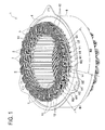
- FIG. 1 is a perspective view of a stator 1 in this embodiment.
- This stator 1 will be used in a three-phase motor having a U-phase, a V-phase, and a W-phase.
- the stator 1 includes a stator core 4 having a plurality of teeth portions 2 (see FIGs. 6 to 8 ) and a plurality of slots 3 (see FIGs. 6 to 8 ), a multi-phase coil 5 of a distributed winding type mounted in the stator core 4, and an outer ring 6 attached on the outer periphery of the stator core 4.
- the multi-phase coil 5 includes a plurality (twenty-four in this embodiment) of unit coils 7.
- the unit coils 7 are set in the slots 3 of the stator core 4 respectively and connected with each other.
- the stator core 4 in this embodiment is a split type core consisting of a plurality of pieces 17 (see FIG. 6 ) connected in an annular form as mentioned later.
- the stator core 4 is illustrated as a single-piece form for convenience.
- the multi-phase coil 5 is composed of a U-phase coil for the U phase, a V-phase coil for the V phase, and a W-phase coil for the W phase.
- Each of the phase coil consists of eight unit coils 7.
- the unit coils 7 constituting each phase coil are mounted in the slots 3 of the stator core 4 in a concentric winding pattern by striding over different-phase slots 3 in which different phase coils are mounted.
- FIG. 2 is a perspective front view of one of the unit coils 7.
- FIG. 3 is a perspective back view of this unit coil 7.
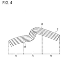
- FIG. 4 is a plan view of this unit coil 7.
- Each unit coil 7 has an almost hexagonal shape in whole, including an outer-layer coil 8 and an inner-layer coil 9 which are concentrically wound. These outer-layer coil 8 and inner-layer coil 9 are formed by winding a single continuous flat conductor wire 10 in plural turns.
- a winding start portion 8a of the outer-layer coil 8 and a winding end portion 9a of the inner-layer coil 9 form a pair of a first connection end portion 11 and a second connection end portion 12 of each unit coil 7.
- the first connection end portion 11 and the second connection end portion 12 are arranged separately on both sides of the unit coil 7 in an axial direction thereof (in a front and back direction relative to drawing sheets of FIGs. 2 and 3 ). Specifically, the first connection end portion 11 is placed on a back side of the unit coil 7 as shown in FIGs. 2 and 3 . The second connection end portion 12 is placed on a front side of the unit coil 7 as shown in FIGs. 2 and 3 .
- the unit coil 7 configured as above has an almost S-shaped bent form in plan view as shown in FIG. 4 .
- the unit coil 7 includes three sections as shown in FIG. 4 , i.e., an outer circumferential portion 7a placed on a side close to an outer circumference of the stator core 4, an inner circumferential portion 7b placed on the other side close to an inner circumference of the stator core 4, and an intermediate portion 7c placed between the positions close to the inner circumference and the outer circumference of the stator core 4.
- the flat conductor wire 10 used for each unit coil 7 is produced by coating a metal wire having a rectangular cross section with insulating resin.
- the metal wire is made of high conductive metal such as copper.
- the insulating resin is a resin having a high insulating property such as enamel and PPS.
- FIG. 5 is a perspective view of two unit coils 7A and 7B overlapping one on the other in the course of manufacturing the cage coil 16 (see FIG. 6 ).
- positioning jigs 21 are placed behind the two unit coils 7A and 7B to position each unit coil 7A, 7B in place.
- the two unit coils 7A and 7B having the same shape are arranged so that respective intermediate portions 7c are located adjacently.
- an inner circumferential portion 7b of the first unit coil 7A is placed under an intermediate portion 7c of the second unit coil 7B. Further, an outer circumferential portion 7a of the second unit coil 7B is placed under an intermediate portion 7c of the first unit coil 7A.
- FIG. 6 is a schematic perspective view showing a state where one piece 17 constituting the split stator core 4 is to be inserted into the cage coil 16.
- the cage coil 16 is produced by overlapping twenty-four unit coils 7 one on another as shown in FIG. 5 .
- the stator core 4 is assembled into an annular form by inserting each piece 17 into hollow spaces of the cage coil 16 from outside. As shown in FIG. 6 , each piece 17 includes two teeth portions 2 and one slot 3 between these teeth portions 2. The pieces 17 are assembled so that their teeth portions 2 are inserted into the hollow spaces of the unit coils 7 constituting the cage coil 16. Then, the outer ring 6 is shrink-fitted on the outer periphery of the stator core 4 as shown in FIG. 1 . Further, eight unit coils 7 constituting each of the U-phase coil, the V-phase coil, and W-phase coil are connected in series with each other through the connection end portions 11 and 12. As above, the stator 1 shown in FIG. 1 is finally completed.
- both the first connection end portion 11 and the second connection end portion 12 of each unit coil 7 are placed above an upper end face of the stator core 4 in an axial direction thereof.
- the second connection end portion 12 of the inner-layer coil 9 is located in a position close to the outer circumference of the stator core 4 and the first connection end portion 11 of the outer-layer coil 8 is located in a position close to the inner circumference of the stator core 4.
- the second connection end portions 12 of the adjacent unit coils 7 constituting a certain phase coil (for example, the "U-phase coil”) are connected with each other in the position close to the outer circumference of the stator core 4.
- the first connection end portions 11 of the adjacent unit coils 7 constituting the certain phase coil (for example, the "U-phase coil) are connected with each other in the position close to the inner circumference of the stator core 4.
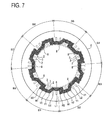
- FIG. 7 is a plan view schematically showing arrangement of only the outer-layer coils 8 of eight unit coils 7 constituting the W-phase coil of the stator core 4.
- FIG. 8 is a plan view schematically showing arrangement of only the inner-layer coils 9 of the eight unit coils 7 constituting the W-phase coil of the stator core 4.
- the stator core 4 is illustrated as a single-piece form for convenience.
- the stator core 4 is divided into first to eighth blocks B1, B2, B3, B4, B5, B6, B7, and B8.
- Each of the blocks B1 to B8 includes a set of six slots 3 to be used for the U-phase coil, the V-phase coil, or the W-phase coil.
- the first block B1 includes a set of two slots 3 for two U phases U1 and U2, two slots 3 for two V phases V1 and V2, and two slots 3 for two W phases W1 and W2.
- Other blocks B2 to B8 are configured in the same way.
- a part of the outer-layer coil 8 constituting one unit coil 7 is inserted into the slot 3 for the W phase W2 of the first block B1. Further, as shown in FIG. 7 , a part of the outer-layer coil 8 constituting the adjacent other unit coil 7 is inserted into the slot 3 for the W phase W2 of the second block B2.
- a part of the inner-layer coil 9 constituting one unit coil 7 is inserted into the slot 3 for the W phase W1 of the first block B1. As shown in FIG. 8 , a part of the inner-layer coil 9 constituting the adjacent other unit coil 7 is inserted into the slot 3 for the W phase W1 of the second block B2.
- FIG. 9 is a perspective view of a portion of the unit coil 7 forming the coil end in the present embodiment.
- FIG. 10 is a perspective view of a part of the coil end of the stator 1 in the present embodiment.
- the first connection end portion 11 and the second connection end portion 12 of each unit coil 7 are placed separately on both sides or edges of each unit coil 7.
- the first and second connection end portions 11 and 12 are illustrated as the same shape.
- two kinds of unit coils 7 are prepared in advance in order to connect the connection end portions 11 and 12 of the adjacent unit coils 7 without using a bus bar or the like.
- the unit coil 7 of one kind is designed so that the first connection end portion 11 is long and the second connection end portion 12 is short
- the unit coil 7 of the other kind is designed so that the first connection end portion 11 is short and the second connection end portion 12 is long.
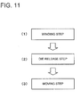
- FIG. 11 is a flowchart showing a sequence of steps of the manufacturing method.
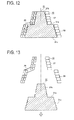
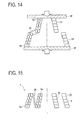
- FIGs. 12 to 15 are cross sectional views schematically showing a state in each step.
- a winding step in (1) of FIG. 11 , firstly, the flat conductor wire 10 is wound in plural turns by use of a winding die 31 as shown in FIG. 12 .
- the winding die 31 includes a single stepped portion 31 a on an outer periphery. On both sides of the stepped portion 31a as a boundary, a small-diameter winding body 31b and a large-diameter winding body 31c having sequentially different sizes in the axial direction are continuously formed in an almost rectangular columnar shape.
- a stepped surface is formed with steps each having a height conforming to the width of the flat conductor wire 10.
- a single flat conductor wire 10 is wound spirally around the outer periphery of each winding body 31c and 31b from a lower end of the large-diameter winding body 31 c of the winding die 31 toward an upper end of the small-diameter winding body 31b.
- the flat conductor wire 10 is extended to form a bridge portion 26.
- each rectangular graphic form indicates the cross section of the flat conductor wire 10 (a hatching is omitted).
- the numeral labeled in each cross section represents the number of turns. The same applies to other FIGs. 13 to 15 .
- a "die release step" in (2) of FIG. 11 the flat conductor wire 10 in a wound form is taken out from the die 31 as shown in FIG. 13 .
- the wound flat conductor wire 10 has a shape transferred from the outer shape of the die 31.
- a portion wound on the small-diameter winding body 31b is referred to as a small coil part 27 and a portion wound on the large-diameter winding body 31c is referred to as a large coil part 28.
- the bridge portion 26 is plastically deformed to relatively move the small coil part 27 into the inside of the large coil part 28 as shown in FIGs. 14 and 15 .
- the small coil part 27 and the large coil part 28 are compressed by a pair of compression plates 36 and 37 to move relatively the coil parts 27 and 28.
- the unit coil 7 including the outer-layer coil 8 and the inner-layer coil 9 in a concentric winding configuration is manufactured as shown in FIG. 15 .
- the winding start portion 8a of the outer-layer coil 8 is located as indicated by "1" on one side or edge of the unit coil 7 in the axial direction and the winding end portion 9a of the inner-layer coil 9 is located on the other side edge of the unit coil 7 in the axial direction as indicated by "10".
- Those winding start portion 8a and winding end portion 9a form the pair of connection end portions 11 and 12 of one unit coil 7.
- the connection end portions 11 and 12 are designed: one is long and the other is short as explained above for connecting adjacent unit coils 7 to each other.
- the distributed winding type multi-phase coil 5 is produced by setting the plurality of unit coils 7 into the plurality of slots 3 of the stator core 4 and connecting the unit coils 7.
- the multi-phase coil 5 is composed of different-phase coils, e.g., the U-phase coil, the V-phase coil, and the W-phase coil.
- the coils of each phase are produced by connecting the unit coils 7 in series with each other. At that time, the first connection end portions 11 of the adjacent unit coils 7 are connected with each other and the second connection end portions 12 of the adjacent unit coils 7 are connected with each other above the stator core 4.
- the stator 1 in the present embodiment does not need, in each unit coil 7, to connect the outer-layer coil 8 and the inner-layer coil 9 to constitute one unit coil 7. Consequently, a connecting work for the unit coils 7 to build up the multi-phase coil 5 can be simplified. Since each unit coil 7 can be reduced in the number of connecting portions of the connection end portions 11 and 12, the coil ends of the stator 1 do not take up mush space. As a result, the upper coil end and the lower coil end of the stator 1 can be made equal in height to each other.
- a connecting portion of the first connection end portions 11 of the adjacent unit coils 7 constituting the same phase coil and a connecting portion of the second connection end portions 12 of the adjacent unit coils 7 are located separately in the position close to the inner circumference and the position close to the outer circumference of the stator core 4. Accordingly, a plurality of the connecting portions of the connection end portions 11 and a plurality of the connecting portions of the connection end portions 12 can be arranged respectively at relatively wide intervals between adjacent connecting portions. During the connecting work, the connecting portions are unlikely to interfere with each other, thus enhancing the efficiency in the connecting work.
- the use of the single continuous flat conductor wire 10 makes it easy to concentrically wind the outer-layer coil 8 and the inner-layer coil 9. Therefore, each unit coil 7 consisting of the outer-layer coil 8 and the inner-layer coil 9 can be easily produced by the single flat conductor wire 10.
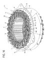
- FIG. 16 is a perspective view of a stator 41 in this embodiment.
- FIG. 17 is a perspective back view of one unit coil 7.
- the stator 41 is different from the stator in the first embodiment in arrangement of connection end portions 11 and 12.
- the unit coil 7 in this embodiment is configured such that a winding start portion 9b of an inner-layer coil 9 and a winding end portion 8b of an outer-layer coil 8 form a first connection end portion 11 and a second connection end portion 12 of the unit coil 7.
- Both the first connection end portion 11 and the second connection end portion 12 are placed in one of two sides or edges of the unit coil 7 in the axial direction thereof, that is, on the edge of the front side.
- both the first connection end portion 11 and the second connection end portion 12 of each unit coil 7 are located above an upper end face of the stator core 4 in an axial direction thereof. Further, both the first connection end portion 11 of the inner-layer coil 9 and the second connection end portion 12 of the outer-layer coil 8 are located in positions, on the same side, close to the outer circumference of the stator core 4 above the upper end face thereof.
- the unit coils 7 between the adjacent unit coils 7 constituting the same phase coil (e.g., a "U-phase coil"), the first connection end portions 11 are connected with each other and the second connection end portions 12 are connected with each other.
- FIG. 18 is a flowchart showing a sequence of steps in the manufacturing method.
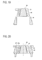
- FIGs. 19 to 22 are cross sectional views schematically showing the steps respectively.
- a flat conductor wire 10 is wound in plural turns on an inner-layer winding die 38 having an almost rectangular columnar shape as shown in FIG. 19 .
- This inner-layer winding die 38 has a stepped surface on an outer periphery formed with steps each having a height conforming to the width of the flat conductor wire 10.
- an outer-layer winding die 39 is placed in a standby condition under the inner-layer winding die 38.
- the single flat conductor wire 10 is spirally wound on the inner-layer winding die 38 from a lower end toward an upper end to form an inner-layer coil 46.
- each rectangular graphic form indicates the cross section of the flat conductor wire 10 (a hatching is omitted).
- the numeral labeled in each cross section represents the number of turns. The same applies to other FIGs. 20 to 22 .
- outer-layer winding die 39 having an almost rectangular cylindrical shape is moved to the outside (the outer periphery) of the inner-layer coil 46 as shown in FIG. 20 .
- This outer-layer winding die 39 has a stepped surface on an outer periphery formed with steps each having a height conforming to the width of the flat conductor wire 10.
- the flat conductor wire 10 is wound in plural turns on the outer periphery of the outer-layer winding die 39 via a bridge portion 47 extending from a winding end portion 46a of the inner-layer coil 46, to form an outer-layer coil 48.
- the flat conductor wire 10 is spirally wound on the outer-layer winding die 39 from an upper end toward a lower end thereof, i.e., in an opposite direction to a forward winding direction of the outer-layer coil 46.
- a winding start portion 46b of the inner-layer coil 46 and a winding end portion 48a of the outer-layer coil 48 are located in one edge or side of the unit coil 7 in the axial direction thereof as indicated by "1" and "10" respectively. Those winding start portion 46b and winding end portion 48a form a pair of connection end portions 11 and 12 of one unit coil 7.
- connection end portions 11 and 12 are designed so that one is longer and the other is shorter for connecting the adjacent unit coils 7 to each other as already explained.
- connection end portions 11 and 12 are designed so that one is longer and the other is shorter as explained above for connecting the adjacent unit coils 7 to each other.
- the distributed winding type multi-phase coil 5 is configured by mounting the unit coils 7 in the slots 3 of the stator core 4 and connecting the unit coils 7.
- the multi-phase coil 5 consists of different-phase coils.
- the coils of each phase are produced by connecting the unit coils 7 in series with each other.
- the first connection end portions 11 of the adjacent unit coils 7 are connected with each other and the second connection end portions 12 of the adjacent unit coils 7 are connected with each other above the stator core 4. Consequently, unlike the stator using the conventional unit coils, the stator 41 in the second embodiment does not need, in each unit coil 7, to connect the outer-layer coil 8 and the inner-layer coil 9 to constitute one unit coil 7.
- each unit coil 7 can be reduced in the number of connecting portions of the connection end portions 11 and 12, the coil ends of the stator 41 do not take up mush space. As a result, the upper coil end and the lower coil end of the stator 41 can be made equal in height to each other.
- a connecting portion of the first connection end portions 11 of the adjacent unit coils 7 constituting the same phase coil and a connecting portion of the second connection end portions 12 of the adjacent unit coils 7 are both located in the positions on the same side close to the outer circumference of the stator core 4. Accordingly, the space above the upper end face of the stator core 4 can be ensured more interiorly than the multi-phase coil 5.
- the connecting portion of the first connection end portions 11 and the connecting portion of the second connection end portions 12 are both located in the positions close to the outer circumference of the stator core 4 and on almost the same circumference, thus enhancing the efficiency in the connecting work.
- the outer-layer coil 8 and the inner-layer coil 9 can be easily obtained by concentrically winding the single continuous flat conductor wire 10.
- the unit coils 7 each including the outer-layer coil 8 and the inner-layer coil 9 in a concentric winding arrangement can be easily manufactured from the single flat conductor wire 10.
- Each of the aforementioned embodiments adopts the unit coil 7 manufactured by concentrically winding two layer coils, i.e., the outer-layer coil 8 and the inner-layer coil 9.
- Alternatives may adopt a unit coil manufactured by concentrically winding three layer coils, i.e., an outer-layer coil, an intermediate coil, and an inner-layer coil, or a unit coil manufactured by concentrically winding four layer coils.
- the aforementioned first embodiment explains the method of manufacturing the unit coil 7 by concentrically winding two layer coils, i.e., the outer-layer coil 8 and the inner-layer coil 9.
- This manufacturing method may be applied to a method of manufacturing a unit coil by concentrically winding three layer coils or four layer coils.
- the connecting portion of the first connection end portions 11 and the connecting portion of the second connection end portions 12 are both located in the positions close to the outer circumference of the stator core 4.
- the connecting portion of the first connection end portions and the connecting portion of the second connection end portions may be both located on the same side close to the inner circumference of the stator core.
- the present invention can be used in for example a motor to be mounted in a hybrid electric vehicle, an electric vehicle, and others.
Landscapes
- Engineering & Computer Science (AREA)
- Power Engineering (AREA)
- Manufacturing & Machinery (AREA)
- Windings For Motors And Generators (AREA)
- Manufacture Of Motors, Generators (AREA)
Abstract
Description
- The present invention relates to a stator including a stator core and a multi-phase coil of a distributed winding type mounted in the stator core, the multi-phase coil consisting of a plurality of unit coils each being formed of a flat conductor wire wound in plural turns, and a method of manufacturing the unit coil to be used in the stator.
- In recent years, the needs for hybrid electric vehicles, electric vehicles, and others have been increased. Accordingly, motors have been studied to be used for the driving power of vehicles. Such motors to be mounted in the vehicles are demanded for high power and downsizing. Particularly, hybrid electric vehicles are strictly demanded for size reduction in view of the placement of a motor in an engine room. Therefore, various studies have been made to achieve downsizing and high power of motors.
- For instance,
Patent Literature 1 listed below discloses a stator including a plurality of unit coils each of which is formed of a rectangular conductor wire (a flat conductor wire) wound in plural turns. The unit coils are mounted in slots of the stator core and connected in respective phases to constitute the distributed winding type multi-phase coil. Each unit coil includes a straight (or linear) portion to be inserted in a slot of the stator core and coil end portions to be placed on end faces of the stator core. On each coil end portion, each unit coil is formed with a crank-shaped portion including no twisting. Each unit coil is mounted in the stator core in a concentrically wound form by striding over slots for different phases. - As disclosed in
Patent Literature 1, the pattern of the multi-phase coil of the stator includes a concentrated winding type and a distributed winding type. The concentrated winding type is achieved by winding a coil (a wire) in concentrating manner on each teeth portion of the stator core. The distributed winding type is achieved by winding a plurality of unit coils each striding over some slots of the stator core so that the unit coils of the different phase or the same phase overlap one on another on each coil end. The stator including the concentrated winding type multi-phase coil could reduce the size of the coil ends. This configuration is effective in downsizing and improvement in efficiency of a motor. The stator core including the distributed winding type multi-phase coil could make a rotating magnetic field inside the stator approximate to a sine wave. This realizes power and lower noise than the concentrated winding type. Both types adopt the flat conductor wire as a coil wire to enhance a coil space factor of the slot, thereby achieving high power of the motor. - On the other hand,
Patent Literature 2 listed below discloses a stator constituted of a multi-phase coil wound on a stator core in a single-phase concentrically winding manner. The multi-phase coil includes a first U-phase coil, a second U-phase coil, a first V-phase coil, a second V-phase coil, a first W-phase coil, and a second W-phase coil, which are unit coils respectively. The first U-phase coil is made by winding a first wire coil, a second wire coil, and a third wire coil in a single-phase concentrically winding manner. A winding end portion of the first wire coil is connected with a winding start portion of the second wire coil, a winding end portion of the second wire coil is connected with a winding start portion of a third wire coil. That is, the first U-phase coil consists of the concentrically wound wire coils arranged in three layers to form a single unit coil. A winding start portion of the first wire coil and a winding end portion of the third wire coil are used as a pair of connection end portions to be connected respectively to a second U-phase coil. The second U-phase coil, the first V-phase coil, the second V-phase coil, the first W-phase coil, and the second W-phase coil are configured in the same manner as above. -
- Patent Literature 1:
JP 2008-104293A - Patent Literature 2:
JP 2008-099441A - It is conceivable that the unit coils in
Patent Literature 1 are configured in a multiple layer concentrically winding manner as disclosed inPatent Literature 2. However, in such a case, the winding start portion and the winding end portion of each layer coil have to be connected with each other. This needs a troublesome connecting work. Further, due to the existence of many connecting portions as mentioned above, the coil ends of the stator take up much space, which hold back downsizing of the stator. - The present invention has been made to solve the above problems and has a purpose to provide a stator capable of making a connecting work of unit coils simple to constitute a multi-phase coil and achieving a reduction in space of coil ends, and a method of manufacturing a unit coil to be used in the stator.
- (1) To achieve the above purpose, a first aspect of the invention provides a stator comprising: a stator core having a plurality of slots; and a multi-phase coil of a distributed type provided in the stator core, the multi-phase coil including a plurality of unit coils, each unit coil being made of a flat conductor wire wound in plural turns, and the unit coils being mounted in the slots of the stator core, wherein each unit coil includes a plurality of concentrically wound layer coils, each layer coil being made of a single continuous flat conductor wire, the layer coils of each unit coil include an outermost layer coil and an innermost layer coil, and a winding start portion or a winding end portion of the outermost layer coil and a winding end portion or a winding start portion of the innermost layer coil form a first connection end portion and a second connection end portion of the unit coil, and the first connection end portion and the second connection end portion are located separately at two edges of the unit coil in an axial direction thereof.
- According to the configuration (1), the distributed winding type multi-phase coil consisting of different-phase coils, e.g., a U-phase coil, a V-phase coil, and a W-phase coil. Each phase coil consists of the plurality of unit coils connected in series with each other. Herein, above the stator core, the first connection end portions of the adjacent unit coils are connected with each other and the second connection end portions are connected with each other. Accordingly, unlike a stator using conventional unit coils, the plurality of layer coils constituting the same unit coil do not have to be connected with each other.
- (2) To achieve the above-mentioned object, preferably, in the above configuration (1), both the first connection end portion and the second connection end portion of each unit coil are located above one end face of the stator core in an axial direction thereof, one of the first connection end portion and the second connection end portion is located in a position close to an inner circumference of the stator core and the other is located in a position close to an outer circumference of the stator core, and of the unit coils, the first connection end portions of adjacent unit coils constituting the same phase are connected with each other and the second connection end portions of the adjacent unit coils constituting the same phase are connected with each other.
- According to the configuration (2), in addition to the operation of the configuration (1), a connecting portion of the first connection end portions of adjacent unit coils constituting the same phase and a connecting portion of the second connection end portions of adjacent unit coils constituting the same phase are located separately in the positions close to the inner circumference of the stator core and the positions close to the outer circumference of the stator core.
- (3) To achieve the above-mentioned object, a second aspect of the invention provides a stator comprising: a stator core having a plurality of slots; and a multi-phase coil of a distributed type provided in the stator core, the multi-phase coil including a plurality of unit coils, each unit coil being made of a flat conductor wire wound in plural turns, and the unit coils being mounted in the slots of the stator core, wherein each unit coil includes a plurality of concentrically wound layer coils, each layer coil being made of a single continuous flat conductor wire, the layer coils of each unit coil include an outermost layer coil and an innermost layer coil, and a winding start portion or a winding end portion of the outermost layer coil and a winding end portion or a winding start portion of the innermost layer coil form a first connection end portion and a second connection end portion of the unit coil, and the first connection end portion and the second connection end portion are both located in one of two edges of the unit coil in an axial direction thereof.
- According to the configuration (3), the distributed winding type multi-phase coil consists of different-phase coils, e.g., a U-phase coil, a V-phase coil, and a W-phase coil. Each phase coil consists of the plurality of unit coils connected in series with each other. In this configuration, above the stator core, the first connection end portions of the adjacent unit coils are connected with each other and the second connection end portions are connected with each other. Consequently, unlike the stator using the conventional unit coils, the plurality of layer coils constituting the same unit coil do not have to be connected with each other.
- (4) To achieve the above-mentioned object, preferably, in the above-mentioned configuration (3), both the first connection end portion and the second connection end portion of each unit coil are located above one end face of the stator core in an axial direction thereof, both the first connection end portion and the second connection end portion are located in positions close to an inner circumference or an outer circumference of the stator core, and of the unit coils, the first connection end portions of adjacent unit coils constituting the same phase are connected with each other and the second connection end portions of the adjacent unit coils constituting the same phase are connected with each other.
- According to the configuration (4), in addition to the operation of the configuration (3), a connecting portion of the first connection end portion of the adjacent unit coils constituting the same phase and a connecting portion of the second connection end portion are both located on the same side close to the inner or outer circumference of the stator core.
- (5) To achieve the above object, a third aspect of the invention provides a method of manufacturing a unit coil to be used in the stator set forth in
claim 1, the unit coil including a plurality of concentrically wound layer coils, the method comprising: a winding step using a winding die of an almost rectangular columnar shape having at least a stepped portion on an outer periphery, the winding die including a plurality of winding bodies that have sequentially different sizes in an axial direction being continuously formed on both sides of the stepped portion, the winding step including winding a single flat conductor wire spirally on an outer periphery of each winding body from one end toward the other end of the winding die and forming a bridge portion extended from the flat conductor wire on the outer periphery of the stepped portion; a die release step of taking out the wound flat conductor wire from the winding die; and a moving step of relatively moving a small coil part wound on a small winding body of the winding bodies into the inside of a large coil part wound on a large winding body of the winding bodies by plastic-deforming the bridge portion. - According to the configuration (5), a plurality of layer coils can be easily made of a single continuous flat conductor wire in a concentrically winding manner.
- (6) To achieve the above object, a fourth aspect of the invention provides a method of manufacturing a unit coil to be used in a stator core having the above configuration (3), the unit coil including two concentrically wound layer coils, the method comprising: an inner-layer winding step of winding a single flat conductor wire spirally on an outer periphery of an inner-layer winding die of an almost rectangular columnar shape, from one end toward the other end, to form an inner-layer coil; an outer-layer winding die moving step of moving an outer-layer winding die of an almost rectangular cylindrical shape into the outside of the inner-layer coil; an outer-layer winding step of winding the flat conductor wire spirally on an outer periphery of the outer-layer winding die from one end toward the other end in an opposite direction to a forward winding direction of the inner-layer coil, through a bridge portion extended from a winding end portion of the inner-layer coil, to form an outer-layer coil; and a die release step of taking out the inner-layer coil and outer-layer coil from the inner-layer winding die and the outer-layer winding die.
- According to the configuration (6), an outer-layer coil and an inner-layer coil can be easily made of a single continuous flat conductor wire in concentrically winding manner.
- According to the configurations (1) to (4) mentioned above, it is possible to simplify a connecting work of unit coils to constitute a multi-phase coil and reduce the space of a coil end of a stator.
- According to the configurations (5) and (6) mentioned above, a unit coil including at least an outer-layer coil and an inner-layer coil can be easily manufactured by use of a single flat conductor wire.
-
-
FIG. 1 is a perspective view of a stator in a first embodiment; -
FIG. 2 is a perspective front view of a unit coil in the first embodiment; -
FIG. 3 is a perspective back view of the unit coil in the first embodiment; -
FIG. 4 is a plan view of the unit coil in the first embodiment; -
FIG. 5 is a perspective view of two stacked or overlapped unit coils in the first embodiment; -
FIG. 6 is a schematic perspective view showing a state where a piece of a split stator core is to be inserted into a coil cage in the first embodiment; -
FIG. 7 is a schematic plan view showing arrangement of only outer-layer coils of eight unit coils constituting a W-phase coil in a stator core in the first embodiment; -
FIG. 8 is a schematic plan view showing arrangement of only inner-layer coils of eight unit coils constituting the W-phase coil in the stator core in the first embodiment; -
FIG. 9 is a perspective view showing a portion of the unit coil constituting a coil end in the first embodiment; -
FIG. 10 is a perspective view showing a part of a coil end of the stator in the first embodiment; -
FIG. 11 is a flowchart showing a sequence of steps in a method of manufacturing a unit coil in the first embodiment; -
FIG. 12 is a cross sectional view schematically showing a "winding step" in the first embodiment; -
FIG. 13 is a cross sectional view schematically showing a "die release step" in the first embodiment; -
FIG. 14 is a cross sectional view schematically showing a "moving step" in the first embodiment; -
FIG. 15 is a cross sectional view schematically showing the "moving step" in the first embodiment; -
FIG. 16 is a perspective view of a stator in a second embodiment; -
FIG. 17 is a perspective back view of a unit coil in the second embodiment; -
FIG. 18 is a flowchart showing a sequence of steps in a method of manufacturing a unit coil in the second embodiment; -
FIG. 19 is a cross sectional view schematically showing an "inner-layer winding step" in the second embodiment; -
FIG. 20 is a cross sectional view schematically showing an "outer-layer winding die moving step" in the second embodiment; -
FIG. 21 is a cross sectional view schematically showing an "outer-layer winding step" in the second embodiment; and -
FIG. 22 is a cross sectional view schematically showing a "die release step" in the second embodiment. - A detailed description of a first preferred embodiment of a stator and a manufacturing method of a unit coil to be used therein embodying the present invention will now be given referring to the accompanying drawings.
-
FIG. 1 is a perspective view of astator 1 in this embodiment. Thisstator 1 will be used in a three-phase motor having a U-phase, a V-phase, and a W-phase. Thestator 1 includes astator core 4 having a plurality of teeth portions 2 (seeFIGs. 6 to 8 ) and a plurality of slots 3 (seeFIGs. 6 to 8 ), amulti-phase coil 5 of a distributed winding type mounted in thestator core 4, and anouter ring 6 attached on the outer periphery of thestator core 4. Themulti-phase coil 5 includes a plurality (twenty-four in this embodiment) of unit coils 7. The unit coils 7 are set in theslots 3 of thestator core 4 respectively and connected with each other. Thestator core 4 in this embodiment is a split type core consisting of a plurality of pieces 17 (seeFIG. 6 ) connected in an annular form as mentioned later. InFIG. 1 , thestator core 4 is illustrated as a single-piece form for convenience. - In this embodiment, the
multi-phase coil 5 is composed of a U-phase coil for the U phase, a V-phase coil for the V phase, and a W-phase coil for the W phase. Each of the phase coil consists of eight unit coils 7. The unit coils 7 constituting each phase coil are mounted in theslots 3 of thestator core 4 in a concentric winding pattern by striding over different-phase slots 3 in which different phase coils are mounted. -
FIG. 2 is a perspective front view of one of the unit coils 7.FIG. 3 is a perspective back view of thisunit coil 7.FIG. 4 is a plan view of thisunit coil 7. Eachunit coil 7 has an almost hexagonal shape in whole, including an outer-layer coil 8 and an inner-layer coil 9 which are concentrically wound. These outer-layer coil 8 and inner-layer coil 9 are formed by winding a single continuousflat conductor wire 10 in plural turns. In the present embodiment, a windingstart portion 8a of the outer-layer coil 8 and a windingend portion 9a of the inner-layer coil 9 form a pair of a firstconnection end portion 11 and a secondconnection end portion 12 of eachunit coil 7. The firstconnection end portion 11 and the secondconnection end portion 12 are arranged separately on both sides of theunit coil 7 in an axial direction thereof (in a front and back direction relative to drawing sheets ofFIGs. 2 and3 ). Specifically, the firstconnection end portion 11 is placed on a back side of theunit coil 7 as shown inFIGs. 2 and3 . The secondconnection end portion 12 is placed on a front side of theunit coil 7 as shown inFIGs. 2 and3 . - The
unit coil 7 configured as above has an almost S-shaped bent form in plan view as shown inFIG. 4 . Herein, theunit coil 7 includes three sections as shown inFIG. 4 , i.e., an outercircumferential portion 7a placed on a side close to an outer circumference of thestator core 4, an innercircumferential portion 7b placed on the other side close to an inner circumference of thestator core 4, and anintermediate portion 7c placed between the positions close to the inner circumference and the outer circumference of thestator core 4. - The
flat conductor wire 10 used for eachunit coil 7 is produced by coating a metal wire having a rectangular cross section with insulating resin. The metal wire is made of high conductive metal such as copper. The insulating resin is a resin having a high insulating property such as enamel and PPS. - To manufacture the
stator 1, a cage-shaped coil ("cage coil") 16 (seeFIG. 6 ) in which a plurality of the unit coils 7 are assembled to overlap one another into an annular cage form. Then, the splittype stator core 4 is attached to thecage coil 16.FIG. 5 is a perspective view of twounit coils FIG. 6 ). InFIG. 5 , positioning jigs 21 are placed behind the twounit coils unit coil FIG. 5 , the twounit coils intermediate portions 7c are located adjacently. InFIG. 5 , an innercircumferential portion 7b of thefirst unit coil 7A is placed under anintermediate portion 7c of thesecond unit coil 7B. Further, an outercircumferential portion 7a of thesecond unit coil 7B is placed under anintermediate portion 7c of thefirst unit coil 7A. -
FIG. 6 is a schematic perspective view showing a state where onepiece 17 constituting thesplit stator core 4 is to be inserted into thecage coil 16. Thecage coil 16 is produced by overlapping twenty-fourunit coils 7 one on another as shown inFIG. 5 . Thestator core 4 is assembled into an annular form by inserting eachpiece 17 into hollow spaces of thecage coil 16 from outside. As shown inFIG. 6 , eachpiece 17 includes twoteeth portions 2 and oneslot 3 between theseteeth portions 2. Thepieces 17 are assembled so that theirteeth portions 2 are inserted into the hollow spaces of the unit coils 7 constituting thecage coil 16. Then, theouter ring 6 is shrink-fitted on the outer periphery of thestator core 4 as shown inFIG. 1 . Further, eightunit coils 7 constituting each of the U-phase coil, the V-phase coil, and W-phase coil are connected in series with each other through theconnection end portions stator 1 shown inFIG. 1 is finally completed. - As shown in
FIG. 1 , in thestator 1, both the firstconnection end portion 11 and the secondconnection end portion 12 of eachunit coil 7 are placed above an upper end face of thestator core 4 in an axial direction thereof. The secondconnection end portion 12 of the inner-layer coil 9 is located in a position close to the outer circumference of thestator core 4 and the firstconnection end portion 11 of the outer-layer coil 8 is located in a position close to the inner circumference of thestator core 4. Of the unit coils 7, the secondconnection end portions 12 of the adjacent unit coils 7 constituting a certain phase coil (for example, the "U-phase coil") are connected with each other in the position close to the outer circumference of thestator core 4. Similarly, the firstconnection end portions 11 of the adjacent unit coils 7 constituting the certain phase coil (for example, the "U-phase coil") are connected with each other in the position close to the inner circumference of thestator core 4. -
FIG. 7 is a plan view schematically showing arrangement of only the outer-layer coils 8 of eightunit coils 7 constituting the W-phase coil of thestator core 4.FIG. 8 is a plan view schematically showing arrangement of only the inner-layer coils 9 of the eightunit coils 7 constituting the W-phase coil of thestator core 4. InFIGs. 7 and8 , thestator core 4 is illustrated as a single-piece form for convenience. - As shown in
FIGs. 7 and8 , thestator core 4 is divided into first to eighth blocks B1, B2, B3, B4, B5, B6, B7, and B8. Each of the blocks B1 to B8 includes a set of sixslots 3 to be used for the U-phase coil, the V-phase coil, or the W-phase coil. For instance, the first block B1 includes a set of twoslots 3 for two U phases U1 and U2, twoslots 3 for two V phases V1 and V2, and twoslots 3 for two W phases W1 and W2. Other blocks B2 to B8 are configured in the same way. - As shown in
FIG. 7 , for instance, a part of the outer-layer coil 8 constituting oneunit coil 7 is inserted into theslot 3 for the W phase W2 of the first block B1. Further, as shown inFIG. 7 , a part of the outer-layer coil 8 constituting the adjacentother unit coil 7 is inserted into theslot 3 for the W phase W2 of the second block B2. On the other hand, as shown inFIG. 8 , a part of the inner-layer coil 9 constituting oneunit coil 7 is inserted into theslot 3 for the W phase W1 of the first block B1. As shown inFIG. 8 , a part of the inner-layer coil 9 constituting the adjacentother unit coil 7 is inserted into theslot 3 for the W phase W1 of the second block B2. -
FIG. 9 is a perspective view of a portion of theunit coil 7 forming the coil end in the present embodiment.FIG. 10 is a perspective view of a part of the coil end of thestator 1 in the present embodiment. As shown inFIG. 9 , the firstconnection end portion 11 and the secondconnection end portion 12 of eachunit coil 7 are placed separately on both sides or edges of eachunit coil 7. InFIG. 9 , the first and secondconnection end portions connection end portions unit coil 7 of one kind is designed so that the firstconnection end portion 11 is long and the secondconnection end portion 12 is short, while theunit coil 7 of the other kind is designed so that the firstconnection end portion 11 is short and the secondconnection end portion 12 is long. - A method of manufacturing the unit coils 7 in the present embodiment will be explained below.
FIG. 11 is a flowchart showing a sequence of steps of the manufacturing method.FIGs. 12 to 15 are cross sectional views schematically showing a state in each step. - In a "winding step" in (1) of
FIG. 11 , firstly, theflat conductor wire 10 is wound in plural turns by use of a windingdie 31 as shown inFIG. 12 . The windingdie 31 includes a single steppedportion 31 a on an outer periphery. On both sides of the steppedportion 31a as a boundary, a small-diameter winding body 31b and a large-diameter winding body 31c having sequentially different sizes in the axial direction are continuously formed in an almost rectangular columnar shape. On the outer periphery of each windingbodies flat conductor wire 10. A singleflat conductor wire 10 is wound spirally around the outer periphery of each windingbody diameter winding body 31 c of the windingdie 31 toward an upper end of the small-diameter winding body 31b. Around the steppedportion 31a, theflat conductor wire 10 is extended to form abridge portion 26. InFIG. 12 , each rectangular graphic form indicates the cross section of the flat conductor wire 10 (a hatching is omitted). The numeral labeled in each cross section represents the number of turns. The same applies to otherFIGs. 13 to 15 . - In a "die release step" in (2) of
FIG. 11 , theflat conductor wire 10 in a wound form is taken out from the die 31 as shown inFIG. 13 . In this state, the woundflat conductor wire 10 has a shape transferred from the outer shape of thedie 31. In this state, a portion wound on the small-diameter winding body 31b is referred to as asmall coil part 27 and a portion wound on the large-diameter winding body 31c is referred to as alarge coil part 28. - In a "moving step" in (3) of
FIG. 11 , thebridge portion 26 is plastically deformed to relatively move thesmall coil part 27 into the inside of thelarge coil part 28 as shown inFIGs. 14 and 15 . In the present embodiment, as shown inFIG. 14 , thesmall coil part 27 and thelarge coil part 28 are compressed by a pair ofcompression plates coil parts - Through the above steps, the
unit coil 7 including the outer-layer coil 8 and the inner-layer coil 9 in a concentric winding configuration is manufactured as shown inFIG. 15 . InFIG. 15 , the windingstart portion 8a of the outer-layer coil 8 is located as indicated by "1" on one side or edge of theunit coil 7 in the axial direction and the windingend portion 9a of the inner-layer coil 9 is located on the other side edge of theunit coil 7 in the axial direction as indicated by "10". Those windingstart portion 8a and windingend portion 9a form the pair ofconnection end portions unit coil 7. Herein, even though the details are not shown inFIGs. 12 to 15 , theconnection end portions - According to the
stator 1 in the first embodiment explained above, the distributed winding typemulti-phase coil 5 is produced by setting the plurality of unit coils 7 into the plurality ofslots 3 of thestator core 4 and connecting the unit coils 7. Herein, themulti-phase coil 5 is composed of different-phase coils, e.g., the U-phase coil, the V-phase coil, and the W-phase coil. The coils of each phase are produced by connecting the unit coils 7 in series with each other. At that time, the firstconnection end portions 11 of the adjacent unit coils 7 are connected with each other and the secondconnection end portions 12 of the adjacent unit coils 7 are connected with each other above thestator core 4. Accordingly, unlike the stator using the conventional unit coils, thestator 1 in the present embodiment does not need, in eachunit coil 7, to connect the outer-layer coil 8 and the inner-layer coil 9 to constitute oneunit coil 7. Consequently, a connecting work for the unit coils 7 to build up themulti-phase coil 5 can be simplified. Since eachunit coil 7 can be reduced in the number of connecting portions of theconnection end portions stator 1 do not take up mush space. As a result, the upper coil end and the lower coil end of thestator 1 can be made equal in height to each other. - According to the
stator 1 in the present embodiment, a connecting portion of the firstconnection end portions 11 of the adjacent unit coils 7 constituting the same phase coil and a connecting portion of the secondconnection end portions 12 of the adjacent unit coils 7 are located separately in the position close to the inner circumference and the position close to the outer circumference of thestator core 4. Accordingly, a plurality of the connecting portions of theconnection end portions 11 and a plurality of the connecting portions of theconnection end portions 12 can be arranged respectively at relatively wide intervals between adjacent connecting portions. During the connecting work, the connecting portions are unlikely to interfere with each other, thus enhancing the efficiency in the connecting work. - Furthermore, according to the method of manufacturing the unit coils 7 in the present embodiment, the use of the single continuous
flat conductor wire 10 makes it easy to concentrically wind the outer-layer coil 8 and the inner-layer coil 9. Therefore, eachunit coil 7 consisting of the outer-layer coil 8 and the inner-layer coil 9 can be easily produced by the singleflat conductor wire 10. - A second embodiment embodying the method of manufacturing a stator and a unit coil to be used therein according to the invention will be explained below in detail referring to the accompanying drawings.
- The following explanation is given with the same reference signs assigned to similar or identical parts to those in the first embodiment and with a focus on different configurations from those in the first embodiment.
-
FIG. 16 is a perspective view of astator 41 in this embodiment.FIG. 17 is a perspective back view of oneunit coil 7. Thestator 41 is different from the stator in the first embodiment in arrangement ofconnection end portions FIG. 17 , theunit coil 7 in this embodiment is configured such that a windingstart portion 9b of an inner-layer coil 9 and a windingend portion 8b of an outer-layer coil 8 form a firstconnection end portion 11 and a secondconnection end portion 12 of theunit coil 7. Both the firstconnection end portion 11 and the secondconnection end portion 12 are placed in one of two sides or edges of theunit coil 7 in the axial direction thereof, that is, on the edge of the front side. - As shown in
FIG. 16 , in thestator 41, both the firstconnection end portion 11 and the secondconnection end portion 12 of eachunit coil 7 are located above an upper end face of thestator core 4 in an axial direction thereof. Further, both the firstconnection end portion 11 of the inner-layer coil 9 and the secondconnection end portion 12 of the outer-layer coil 8 are located in positions, on the same side, close to the outer circumference of thestator core 4 above the upper end face thereof. Of the unit coils 7, between the adjacent unit coils 7 constituting the same phase coil (e.g., a "U-phase coil"), the firstconnection end portions 11 are connected with each other and the secondconnection end portions 12 are connected with each other. - On the other hand, the present embodiment is different from the first embodiment in the method of manufacturing the unit coils 7. The manufacturing method of the second embodiment is explained below.
FIG. 18 is a flowchart showing a sequence of steps in the manufacturing method.FIGs. 19 to 22 are cross sectional views schematically showing the steps respectively. - In an "inner-layer winding step" in (1) of
FIG. 18 , aflat conductor wire 10 is wound in plural turns on an inner-layer winding die 38 having an almost rectangular columnar shape as shown inFIG. 19 . This inner-layer winding die 38 has a stepped surface on an outer periphery formed with steps each having a height conforming to the width of theflat conductor wire 10. In this stage, an outer-layer winding die 39 is placed in a standby condition under the inner-layer winding die 38. The singleflat conductor wire 10 is spirally wound on the inner-layer winding die 38 from a lower end toward an upper end to form an inner-layer coil 46. InFIG. 19 , each rectangular graphic form indicates the cross section of the flat conductor wire 10 (a hatching is omitted). The numeral labeled in each cross section represents the number of turns. The same applies to otherFIGs. 20 to 22 . - In an "outer-layer winding die moving step" in (2) of
FIG. 18 , the outer-layer winding die 39 having an almost rectangular cylindrical shape is moved to the outside (the outer periphery) of the inner-layer coil 46 as shown inFIG. 20 . This outer-layer winding die 39 has a stepped surface on an outer periphery formed with steps each having a height conforming to the width of theflat conductor wire 10. - In an "outer-layer winding step" in (3) of
FIG. 18 , as shown inFIG. 21 , theflat conductor wire 10 is wound in plural turns on the outer periphery of the outer-layer winding die 39 via abridge portion 47 extending from a windingend portion 46a of the inner-layer coil 46, to form an outer-layer coil 48. At that time, theflat conductor wire 10 is spirally wound on the outer-layer winding die 39 from an upper end toward a lower end thereof, i.e., in an opposite direction to a forward winding direction of the outer-layer coil 46. - In a "die release step" in (4) of
FIG. 18 , the inner-layer coil 46 and the outer-layer coil 48 are taken out from the inner-layer winding die 38 and the outer-layer winding die 39. Accordingly, as shown inFIG. 22 , oneunit coil 7 including the inner-layer coil 46 and the outer-layer coil 48 in a concentric winding configuration can be manufactured. InFIG. 22 , a windingstart portion 46b of the inner-layer coil 46 and a windingend portion 48a of the outer-layer coil 48 are located in one edge or side of theunit coil 7 in the axial direction thereof as indicated by "1" and "10" respectively. Those windingstart portion 46b and windingend portion 48a form a pair ofconnection end portions unit coil 7. Although the details are not illustrated inFIGs. 12 to 15 , theconnection end portions FIGs. 19 to 22 , theconnection end portions - According to the
stator 41 in the present embodiment, as explained above, the distributed winding typemulti-phase coil 5 is configured by mounting the unit coils 7 in theslots 3 of thestator core 4 and connecting the unit coils 7. Themulti-phase coil 5 consists of different-phase coils. The coils of each phase are produced by connecting the unit coils 7 in series with each other. At that time, the firstconnection end portions 11 of the adjacent unit coils 7 are connected with each other and the secondconnection end portions 12 of the adjacent unit coils 7 are connected with each other above thestator core 4. Consequently, unlike the stator using the conventional unit coils, thestator 41 in the second embodiment does not need, in eachunit coil 7, to connect the outer-layer coil 8 and the inner-layer coil 9 to constitute oneunit coil 7. Consequently, a connecting work for the unit coils 7 to build up themulti-phase coil 5 can be simplified. Since eachunit coil 7 can be reduced in the number of connecting portions of theconnection end portions stator 41 do not take up mush space. As a result, the upper coil end and the lower coil end of thestator 41 can be made equal in height to each other. - According to the
stator 41 in the present embodiment, a connecting portion of the firstconnection end portions 11 of the adjacent unit coils 7 constituting the same phase coil and a connecting portion of the secondconnection end portions 12 of the adjacent unit coils 7 are both located in the positions on the same side close to the outer circumference of thestator core 4. Accordingly, the space above the upper end face of thestator core 4 can be ensured more interiorly than themulti-phase coil 5. The connecting portion of the firstconnection end portions 11 and the connecting portion of the secondconnection end portions 12 are both located in the positions close to the outer circumference of thestator core 4 and on almost the same circumference, thus enhancing the efficiency in the connecting work. - According to the method of manufacturing the unit coils 7 in the present embodiment, the outer-
layer coil 8 and the inner-layer coil 9 can be easily obtained by concentrically winding the single continuousflat conductor wire 10. The unit coils 7 each including the outer-layer coil 8 and the inner-layer coil 9 in a concentric winding arrangement can be easily manufactured from the singleflat conductor wire 10. - The present invention is not limited to each of the aforementioned embodiments and may be embodied in other specific forms without departing from the essential characteristics thereof.
- (1) Each of the aforementioned embodiments adopts the
unit coil 7 manufactured by concentrically winding two layer coils, i.e., the outer-layer coil 8 and the inner-layer coil 9. Alternatives may adopt a unit coil manufactured by concentrically winding three layer coils, i.e., an outer-layer coil, an intermediate coil, and an inner-layer coil, or a unit coil manufactured by concentrically winding four layer coils. - (2) The aforementioned first embodiment explains the method of manufacturing the
unit coil 7 by concentrically winding two layer coils, i.e., the outer-layer coil 8 and the inner-layer coil 9. This manufacturing method may be applied to a method of manufacturing a unit coil by concentrically winding three layer coils or four layer coils. - (3) In the aforementioned second embodiment, the connecting portion of the first
connection end portions 11 and the connecting portion of the secondconnection end portions 12 are both located in the positions close to the outer circumference of thestator core 4. As an alternative, the connecting portion of the first connection end portions and the connecting portion of the second connection end portions may be both located on the same side close to the inner circumference of the stator core. - The present invention can be used in for example a motor to be mounted in a hybrid electric vehicle, an electric vehicle, and others.
-
- 1
- Stator
- 3
- Slot
- 4
- Stator core
- 5
- Multi-phase coil
- 7
- Unit coil
- 7A
- Unit coil
- 7B
- Unit coil
- 8
- Outer-layer coil
- 8a
- Winding start portion
- 8b
- Winding end portion
- 9
- Inner-layer coil
- 9a
- Winding end portion
- 9b
- Winding start portion
- 10
- Flat conductor wire
- 11
- First connection end portion
- 12
- Second connection end portion
- 26
- Bridge portion
- 27
- Small coil part
- 28
- Large coil part
- 31
- Winding die
- 31a
- Shoulder
- 31b
- Small-diameter winding body
- 31c
- Large-diameter winding body
- 38
- Inner-layer winding die
- 39
- Outer-layer winding die
- 41
- Stator
- 46
- Inner-layer coil
- 46a
- Winding end portion
- 46b
- Winding start portion
- 47
- Bridge portion
- 48
- Outer-layer coil
- 48a
- Winding end portion
Claims (6)
- A stator comprising:a stator core having a plurality of slots; anda multi-phase coil of a distributed type provided in the stator core,the multi-phase coil including a plurality of unit coils, each unit coil being made of a flat conductor wire wound in plural turns, and the unit coils being mounted in the slots of the stator core,wherein each unit coil includes a plurality of concentrically wound layer coils, each layer coil being made of a single continuous flat conductor wire,the layer coils of each unit coil include an outermost layer coil and an innermost layer coil, and a winding start portion or a winding end portion of the outermost layer coil and a winding end portion or a winding start portion of the innermost layer coil form a first connection end portion and a second connection end portion of the unit coil, andthe first connection end portion and the second connection end portion are located separately at two edges of the unit coil in an axial direction thereof.
- The stator according to claim 1, wherein
both the first connection end portion and the second connection end portion of each unit coil are located above one end face of the stator core in an axial direction thereof, one of the first connection end portion and the second connection end portion is located in a position close to an inner circumference of the stator core and the other is located in a position close to an outer circumference of the stator core, and
of the unit coils, the first connection end portions of adjacent unit coils constituting the same phase are connected with each other and the second connection end portions of the adjacent unit coils constituting the same phase are connected with each other. - A stator comprising:a stator core having a plurality of slots; anda multi-phase coil of a distributed type provided in the stator core,the multi-phase coil including a plurality of unit coils, each unit coil being made of a flat conductor wire wound in plural turns, and the unit coils being mounted in the slots of the stator core,wherein each unit coil includes a plurality of concentrically wound layer coils, each layer coil being made of a single continuous flat conductor wire,the layer coils of each unit coil include an outermost layer coil and an innermost layer coil, and a winding start portion or a winding end portion of the outermost layer coil and a winding end portion or a winding start portion of the innermost layer coil form a first connection end portion and a second connection end portion of the unit coil, andthe first connection end portion and the second connection end portion are both located in one of two edges of the unit coil in an axial direction thereof.
- The stator according to claim 3, wherein
both the first connection end portion and the second connection end portion of each unit coil are located above one end face of the stator core in an axial direction thereof, both the first connection end portion and the second connection end portion are located in positions close to an inner circumference or an outer circumference of the stator core, and
of the unit coils, the first connection end portions of adjacent unit coils constituting the same phase are connected with each other and the second connection end portions of the adjacent unit coils constituting the same phase are connected with each other. - A method of manufacturing a unit coil to be used in the stator set forth in claim 1, the unit coil including a plurality of concentrically wound layer coils, the method comprising:a winding step using a winding die of an almost rectangular columnar shape having at least a stepped portion on an outer periphery, the winding die including a plurality of winding bodies that have sequentially different sizes in an axial direction being continuously formed on both sides of the stepped portion, the winding step including winding a single flat conductor wire spirally on an outer periphery of each winding body from one end toward the other end of the winding die and forming a bridge portion extended from the flat conductor wire on the outer periphery of the stepped portion;a die release step of taking out the wound flat conductor wire from the winding die; anda moving step of relatively moving a small coil part wound on a small winding body of the winding bodies into the inside of a large coil part wound on a large winding body of the winding bodies by plastic-deforming the bridge portion.
- A method of manufacturing a unit coil to be used in the stator set forth in claim 3, the unit coil including two concentrically wound layer coils, the method comprising:an inner-layer winding step of winding a single flat conductor wire spirally on an outer periphery of an inner-layer winding die of an almost rectangular columnar shape, from one end toward the other end, to form an inner-layer coil;an outer-layer winding die moving step of moving an outer-layer winding die of an almost rectangular cylindrical shape into the outside of the inner-layer coil;an outer-layer winding step of winding the flat conductor wire spirally on an outer periphery of the outer-layer winding die from one end toward the other end in an opposite direction to a forward winding direction of the inner-layer coil, through a bridge portion extended from a winding end portion of the inner-layer coil, to form an outer-layer coil; anda die release step of taking out the inner-layer coil and outer-layer coil from the inner-layer winding die and the outer-layer winding die.
Applications Claiming Priority (1)
| Application Number | Priority Date | Filing Date | Title |
|---|---|---|---|
| PCT/JP2010/059943 WO2011155061A1 (en) | 2010-06-11 | 2010-06-11 | Stator and method for manufacturing unit coil used for same |
Publications (2)
| Publication Number | Publication Date |
|---|---|
| EP2418758A1 true EP2418758A1 (en) | 2012-02-15 |
| EP2418758A4 EP2418758A4 (en) | 2017-03-15 |
Family
ID=45097690
Family Applications (1)
| Application Number | Title | Priority Date | Filing Date |
|---|---|---|---|
| EP10835272.5A Withdrawn EP2418758A4 (en) | 2010-06-11 | 2010-06-11 | Stator and method for manufacturing unit coil used for same |
Country Status (5)
| Country | Link |
|---|---|
| US (1) | US8587177B2 (en) |
| EP (1) | EP2418758A4 (en) |
| JP (1) | JP5234173B2 (en) |
| CN (1) | CN102668332B (en) |
| WO (1) | WO2011155061A1 (en) |
Families Citing this family (44)
| Publication number | Priority date | Publication date | Assignee | Title |
|---|---|---|---|---|
| US20120223611A1 (en) * | 2009-11-05 | 2012-09-06 | Toyota Jidosha Kabushiki Kaisha | Stator and method for manufacturing stator |
| JP5363403B2 (en) * | 2010-04-19 | 2013-12-11 | トヨタ自動車株式会社 | motor |
| JP2012152028A (en) * | 2011-01-19 | 2012-08-09 | Denso Corp | Rotary electric machine |
| JP5488517B2 (en) * | 2011-03-31 | 2014-05-14 | 株式会社豊田自動織機 | Electric motor and electric compressor using electric motor |
| US20140030078A1 (en) * | 2011-04-05 | 2014-01-30 | Toyota Jidosha Kabushiki Kaisha | Stator and method of manufacturing stator |
| JP5789570B2 (en) * | 2012-07-03 | 2015-10-07 | アイシン・エィ・ダブリュ株式会社 | Stator |
| JP5804095B2 (en) * | 2013-01-22 | 2015-11-04 | トヨタ自動車株式会社 | Stator and stator manufacturing method |
| JP5889235B2 (en) * | 2013-03-22 | 2016-03-22 | 三菱電機株式会社 | Armature of rotating electric machine and method for manufacturing the same |
| JP5850878B2 (en) * | 2013-05-16 | 2016-02-03 | 本田技研工業株式会社 | Segment conductor type stator of rotating electric machine and method of manufacturing the same |
| JP6225549B2 (en) * | 2013-08-08 | 2017-11-08 | 日産自動車株式会社 | Winding structure of rotating electrical machine |
| CN105432000B (en) * | 2013-08-26 | 2018-06-08 | 三菱电机株式会社 | rotating electrical machine |
| FR3019948B1 (en) | 2014-04-10 | 2017-12-22 | Moteurs Leroy-Somer | ROTOR OF ELECTRIC ROTATING MACHINE. |
| JP6341288B2 (en) * | 2014-09-01 | 2018-06-13 | アイシン・エィ・ダブリュ株式会社 | Stator assembly method and stator |
| CN104218746B (en) * | 2014-09-04 | 2016-08-24 | 广西师范大学 | Three-phase symmetrical prints the manufacture method of winding |
| WO2016104645A1 (en) * | 2014-12-26 | 2016-06-30 | アイシン・エィ・ダブリュ株式会社 | Stator production method and coil |
| ITBO20150189A1 (en) * | 2015-04-16 | 2016-10-16 | Magneti Marelli Spa | METHOD OF CONSTRUCTION OF AN ELECTRIC MACHINE WITH A STATORIC WINDING WITH RIGID BARS |
| CN106300717B (en) * | 2016-06-17 | 2018-08-03 | 浙江方正电机股份有限公司 | three-phase motor stator |
| JP6785528B2 (en) * | 2016-10-14 | 2020-11-18 | Nittoku株式会社 | Winding device and winding method |
| JP6389501B2 (en) | 2016-11-30 | 2018-09-12 | 公明 岩谷 | Coil for rotating machine and rotating machine |
| DE112018000190T5 (en) * | 2017-02-23 | 2019-10-02 | Borgwarner Inc. | Electric machine with a stator that has multi-layered end loops |
| DE102017128827A1 (en) * | 2017-12-05 | 2019-06-06 | Ebm-Papst Mulfingen Gmbh & Co. Kg | Multi-tooth coil winding for a 2-phase induction machine |
| CN108512331B (en) * | 2018-05-23 | 2024-03-01 | 醴陵市辉泰电子有限公司 | Coil end structure of double-layer winding |
| WO2020044752A1 (en) * | 2018-08-31 | 2020-03-05 | 日本電産株式会社 | Stator manufacturing method |
| JP7137421B2 (en) | 2018-09-28 | 2022-09-14 | 株式会社小松製作所 | Stator and rotating electric machine |
| KR20200056742A (en) * | 2018-11-15 | 2020-05-25 | 주식회사 코렌스글로벌 | Motor with flat wire |
| JP7135987B2 (en) * | 2019-04-19 | 2022-09-13 | 株式会社デンソー | Alignment device and method for manufacturing alignment coil |
| ES2985156T3 (en) * | 2019-08-30 | 2024-11-04 | Abb Schweiz Ag | A method and arrangement for producing a segment coil |
| DE102019213474A1 (en) * | 2019-09-05 | 2021-03-11 | Zf Friedrichshafen Ag | Coil with hairpin winding and process for their manufacture |
| WO2021065433A1 (en) * | 2019-09-30 | 2021-04-08 | 日本電産株式会社 | Motor coil manufacturing method, motor manufacturing method, and motor coil manufacturing device |
| CN110855045A (en) * | 2019-10-21 | 2020-02-28 | 浙江龙芯电驱动科技有限公司 | 72-slot 6-layer flat copper wire hybrid winding structure and motor applying same |
| US11228216B2 (en) * | 2019-11-15 | 2022-01-18 | Ford Global Technologies, Llc | Stator for electric machine with conductors with varying cross-sectional shapes |
| CN113615044B (en) * | 2020-03-05 | 2024-08-13 | 株式会社东芝 | Stator of rotating electrical machine and rotating electrical machine |
| JP7581649B2 (en) * | 2020-04-20 | 2024-11-13 | 株式会社デンソー | Rotating Electric Machine |
| JP7058698B2 (en) * | 2020-09-23 | 2022-04-22 | 三菱電機株式会社 | Rotating electric machine |
| CN112072808B (en) * | 2020-09-28 | 2025-09-12 | 福建闽光电机制造有限公司 | A three-row wire motor stator |
| WO2022129796A1 (en) * | 2020-12-17 | 2022-06-23 | Nidec Psa Emotors | Coil intended to be inserted in the notches of a stator of a rotating electrical machine |
| DE102022108615B4 (en) * | 2021-04-09 | 2026-04-02 | Borgwarner Inc. | Diamond coil stator with parallel paths and balanced winding arrangement |
| DE102022108587A1 (en) * | 2021-04-09 | 2022-10-13 | Borgwarner Inc. | STATOR WITH PRINTED END WINDINGS AND METHOD OF MAKING THE SAME |
| CN116846116A (en) * | 2022-03-25 | 2023-10-03 | 日本电产株式会社 | Stator and coil manufacturing equipment |
| CN117411222A (en) * | 2022-07-13 | 2024-01-16 | 博格华纳公司 | Laminated windings for electrical machines with series connections on outer diameter |
| CN117859255A (en) * | 2022-08-05 | 2024-04-09 | 宁德时代(上海)智能科技有限公司 | Flat wire motor and its stator |
| WO2025093120A1 (en) * | 2023-11-01 | 2025-05-08 | Friedrich Grimm | Electric machine, helicopter, autonomous spherical vehicle, and aircraft |
| WO2025205332A1 (en) * | 2024-03-29 | 2025-10-02 | 株式会社アイシン | Stator |
| WO2026048453A1 (en) * | 2024-08-29 | 2026-03-05 | ニデック株式会社 | Stator, motor, and method for manufacturing stator |
Family Cites Families (16)
| Publication number | Priority date | Publication date | Assignee | Title |
|---|---|---|---|---|
| DE4130016A1 (en) * | 1990-12-24 | 1993-03-11 | Erich Rabe | ELECTRONICALLY COMMUTED DC GENERATOR |
| US5714824A (en) | 1994-06-23 | 1998-02-03 | Hydro-Quebec | Conductor section for a stator frame of a polyphase dynamoelectric machine |
| JP3752431B2 (en) * | 2001-02-28 | 2006-03-08 | 株式会社日立製作所 | Rotating electric machine and manufacturing method thereof |
| JP4320516B2 (en) * | 2001-07-30 | 2009-08-26 | セイコーエプソン株式会社 | Inkjet recording apparatus provided with a paper discharge device and the paper discharge device |
| GB0206645D0 (en) * | 2002-03-21 | 2002-05-01 | Rolls Royce Plc | Improvements in or relating to magnetic coils for electrical machines |
| JP3613262B2 (en) * | 2002-04-26 | 2005-01-26 | 三菱電機株式会社 | Rotating electric machine and manufacturing method thereof |
| US6555942B1 (en) * | 2002-05-10 | 2003-04-29 | Chun-Pu Hsu | Assembly type stator structure having flat wire wound coils |
| JP3906124B2 (en) * | 2002-07-25 | 2007-04-18 | 本田技研工業株式会社 | Armature coil of rotating machine |
| WO2006080465A1 (en) * | 2005-01-28 | 2006-08-03 | Mostec Inc. | Coil, coil unit, stator and rotor |
| JP5055937B2 (en) * | 2006-10-12 | 2012-10-24 | 株式会社明電舎 | Winding insulation structure of rotating electrical machine |
| JP4234749B2 (en) * | 2006-10-19 | 2009-03-04 | 株式会社日立製作所 | Rotating electric machine, crank-shaped continuous winding coil, distributed winding stator and method for forming them |
| JP4509088B2 (en) | 2006-11-10 | 2010-07-21 | 三菱電機株式会社 | Manufacturing method of rotating electrical machines |
| US7671495B2 (en) * | 2006-11-20 | 2010-03-02 | Asmo Co., Ltd. | Armature and motor |
| JP2010063323A (en) * | 2008-09-06 | 2010-03-18 | Sumitomo Electric Ind Ltd | Coil member and stator |
| JP2010067790A (en) | 2008-09-10 | 2010-03-25 | Sumitomo Electric Ind Ltd | Edge-wise coil and manufacturing device thereof |
| JP5278546B2 (en) * | 2009-12-18 | 2013-09-04 | トヨタ自動車株式会社 | Stator |
-
2010
- 2010-06-11 JP JP2011505291A patent/JP5234173B2/en not_active Expired - Fee Related
- 2010-06-11 EP EP10835272.5A patent/EP2418758A4/en not_active Withdrawn
- 2010-06-11 CN CN201080017079.9A patent/CN102668332B/en not_active Expired - Fee Related
- 2010-06-11 WO PCT/JP2010/059943 patent/WO2011155061A1/en not_active Ceased
- 2010-06-11 US US13/131,245 patent/US8587177B2/en not_active Expired - Fee Related
Non-Patent Citations (1)
| Title |
|---|
| See references of WO2011155061A1 * |
Also Published As
| Publication number | Publication date |
|---|---|
| CN102668332A (en) | 2012-09-12 |
| US8587177B2 (en) | 2013-11-19 |
| WO2011155061A1 (en) | 2011-12-15 |
| JP5234173B2 (en) | 2013-07-10 |
| JPWO2011155061A1 (en) | 2013-08-01 |
| EP2418758A4 (en) | 2017-03-15 |
| US20120007460A1 (en) | 2012-01-12 |
| CN102668332B (en) | 2015-04-08 |
Similar Documents
| Publication | Publication Date | Title |
|---|---|---|
| US8587177B2 (en) | Stator and method of manufacturing unit coil to be used therein | |
| JP5560176B2 (en) | Motor and motor manufacturing method | |
| JP5418686B2 (en) | Stator and stator manufacturing method | |
| EP3007319B1 (en) | Rotary electric machine, and manufacturing method therefor | |
| US9712010B2 (en) | Motor having a cage wave stator winding | |
| US8427024B2 (en) | Stator | |
| US8884489B2 (en) | Motor | |
| CN104584391B (en) | Rotary electric machine and manufacturing method therefor | |
| JP5370491B2 (en) | Stator and stator manufacturing method | |
| US10236738B2 (en) | Rotary electric machine | |
| US20080201935A1 (en) | Manufacturing Method for Rotary Electric Machine and Stator | |
| JP5174485B2 (en) | Rotating electric machine | |
| JP2009195006A (en) | Rotating electric machine | |
| EP2353217B1 (en) | Stator and coil | |
| US20210099039A1 (en) | Stator and electric rotating machine | |
| KR20150100425A (en) | Stator and winding method for stator coil | |
| WO2014157621A1 (en) | Stator structure | |
| CN212033857U (en) | Motor stator and motor | |
| JP2011229290A (en) | Motor | |
| CN214124958U (en) | Motor stator and motor | |
| CN216216161U (en) | Stator winding, motor stator and motor | |
| CN214124960U (en) | Motor stator and motor | |
| CN214124963U (en) | Motor stator and motor | |
| EP4009502A1 (en) | A method for manufacturing a stator for an electrical machine | |
| CN116131498A (en) | Stator and motor |
Legal Events
| Date | Code | Title | Description |
|---|---|---|---|
| PUAI | Public reference made under article 153(3) epc to a published international application that has entered the european phase |
Free format text: ORIGINAL CODE: 0009012 |
|
| 17P | Request for examination filed |
Effective date: 20110617 |
|
| AK | Designated contracting states |
Kind code of ref document: A1 Designated state(s): AL AT BE BG CH CY CZ DE DK EE ES FI FR GB GR HR HU IE IS IT LI LT LU LV MC MK MT NL NO PL PT RO SE SI SK SM TR |
|
| AX | Request for extension of the european patent |
Extension state: BA ME RS |
|
| RBV | Designated contracting states (corrected) |
Designated state(s): AL AT BE BG CH CY CZ DE DK EE ES FI FR GB GR HR HU IE IS IT LI LT LU LV MC MK MT NL NO PL PT RO SE SI SK SM TR |
|
| RAP1 | Party data changed (applicant data changed or rights of an application transferred) |
Owner name: TOYOTA JIDOSHA KABUSHIKI KAISHA |
|
| DAX | Request for extension of the european patent (deleted) | ||
| RA4 | Supplementary search report drawn up and despatched (corrected) |
Effective date: 20170213 |
|
| RIC1 | Information provided on ipc code assigned before grant |
Ipc: H02K 15/04 20060101ALI20170207BHEP Ipc: H02K 15/06 20060101ALI20170207BHEP Ipc: H02K 3/04 20060101AFI20170207BHEP |
|
| STAA | Information on the status of an ep patent application or granted ep patent |
Free format text: STATUS: REQUEST FOR EXAMINATION WAS MADE |
|
| STAA | Information on the status of an ep patent application or granted ep patent |
Free format text: STATUS: THE APPLICATION IS DEEMED TO BE WITHDRAWN |
|
| 18D | Application deemed to be withdrawn |
Effective date: 20170913 |