EP2418566A1 - Electronic device including pivotable touch-sensitive display providing haptic feedback - Google Patents
Electronic device including pivotable touch-sensitive display providing haptic feedback Download PDFInfo
- Publication number
- EP2418566A1 EP2418566A1 EP10172557A EP10172557A EP2418566A1 EP 2418566 A1 EP2418566 A1 EP 2418566A1 EP 10172557 A EP10172557 A EP 10172557A EP 10172557 A EP10172557 A EP 10172557A EP 2418566 A1 EP2418566 A1 EP 2418566A1
- Authority
- EP
- European Patent Office
- Prior art keywords
- electronic device
- support tray
- touch
- sensitive display
- housing
- Prior art date
- Legal status (The legal status is an assumption and is not a legal conclusion. Google has not performed a legal analysis and makes no representation as to the accuracy of the status listed.)
- Granted
Links
Images

Classifications
-
- G—PHYSICS
- G06—COMPUTING OR CALCULATING; COUNTING
- G06F—ELECTRIC DIGITAL DATA PROCESSING
- G06F3/00—Input arrangements for transferring data to be processed into a form capable of being handled by the computer; Output arrangements for transferring data from processing unit to output unit, e.g. interface arrangements
- G06F3/01—Input arrangements or combined input and output arrangements for interaction between user and computer
- G06F3/016—Input arrangements with force or tactile feedback as computer generated output to the user
-
- G—PHYSICS
- G06—COMPUTING OR CALCULATING; COUNTING
- G06F—ELECTRIC DIGITAL DATA PROCESSING
- G06F1/00—Details not covered by groups G06F3/00 - G06F13/00 and G06F21/00
- G06F1/16—Constructional details or arrangements
- G06F1/1613—Constructional details or arrangements for portable computers
- G06F1/1626—Constructional details or arrangements for portable computers with a single-body enclosure integrating a flat display, e.g. Personal Digital Assistants [PDAs]
-
- G—PHYSICS
- G06—COMPUTING OR CALCULATING; COUNTING
- G06F—ELECTRIC DIGITAL DATA PROCESSING
- G06F1/00—Details not covered by groups G06F3/00 - G06F13/00 and G06F21/00
- G06F1/16—Constructional details or arrangements
- G06F1/1613—Constructional details or arrangements for portable computers
- G06F1/1633—Constructional details or arrangements of portable computers not specific to the type of enclosures covered by groups G06F1/1615 - G06F1/1626
- G06F1/1637—Details related to the display arrangement, including those related to the mounting of the display in the housing
- G06F1/1643—Details related to the display arrangement, including those related to the mounting of the display in the housing the display being associated to a digitizer, e.g. laptops that can be used as penpads
-
- G—PHYSICS
- G06—COMPUTING OR CALCULATING; COUNTING
- G06F—ELECTRIC DIGITAL DATA PROCESSING
- G06F1/00—Details not covered by groups G06F3/00 - G06F13/00 and G06F21/00
- G06F1/16—Constructional details or arrangements
- G06F1/1613—Constructional details or arrangements for portable computers
- G06F1/1633—Constructional details or arrangements of portable computers not specific to the type of enclosures covered by groups G06F1/1615 - G06F1/1626
- G06F1/1684—Constructional details or arrangements related to integrated I/O peripherals not covered by groups G06F1/1635 - G06F1/1675
-
- G—PHYSICS
- G06—COMPUTING OR CALCULATING; COUNTING
- G06F—ELECTRIC DIGITAL DATA PROCESSING
- G06F3/00—Input arrangements for transferring data to be processed into a form capable of being handled by the computer; Output arrangements for transferring data from processing unit to output unit, e.g. interface arrangements
- G06F3/01—Input arrangements or combined input and output arrangements for interaction between user and computer
- G06F3/03—Arrangements for converting the position or the displacement of a member into a coded form
- G06F3/033—Pointing devices displaced or positioned by the user, e.g. mice, trackballs, pens or joysticks; Accessories therefor
- G06F3/0338—Pointing devices displaced or positioned by the user, e.g. mice, trackballs, pens or joysticks; Accessories therefor with detection of limited linear or angular displacement of an operating part of the device from a neutral position, e.g. isotonic or isometric joysticks
-
- G—PHYSICS
- G06—COMPUTING OR CALCULATING; COUNTING
- G06F—ELECTRIC DIGITAL DATA PROCESSING
- G06F3/00—Input arrangements for transferring data to be processed into a form capable of being handled by the computer; Output arrangements for transferring data from processing unit to output unit, e.g. interface arrangements
- G06F3/01—Input arrangements or combined input and output arrangements for interaction between user and computer
- G06F3/048—Interaction techniques based on graphical user interfaces [GUI]
- G06F3/0487—Interaction techniques based on graphical user interfaces [GUI] using specific features provided by the input device, e.g. functions controlled by the rotation of a mouse with dual sensing arrangements, or of the nature of the input device, e.g. tap gestures based on pressure sensed by a digitiser
- G06F3/0488—Interaction techniques based on graphical user interfaces [GUI] using specific features provided by the input device, e.g. functions controlled by the rotation of a mouse with dual sensing arrangements, or of the nature of the input device, e.g. tap gestures based on pressure sensed by a digitiser using a touch-screen or digitiser, e.g. input of commands through traced gestures
Definitions
- the present disclosure relates to an electronic device including a touch-sensitive display and an actuator to provide feedback.
- Portable electronic devices have gained widespread use and may provide a variety of functions including, for example, telephonic, electronic text messaging and other personal information manager (PIM) application functions.
- Portable electronic devices can include several types of devices including mobile stations such as simple cellular phones, smart phones, Personal Digital Assistants (PDAs), and laptop computers.
- mobile stations such as simple cellular phones, smart phones, Personal Digital Assistants (PDAs), and laptop computers.
- PDAs Personal Digital Assistants
- Touch-sensitive devices constructed of a display, such as a liquid crystal display (LCD), with a touch-sensitive overlay are useful on such handheld devices as such handheld devices are small and are therefore limited in space available for user input and output devices. Further, the screen content on the touch-sensitive devices can be modified depending on the functions and operations being performed.
- LCD liquid crystal display
- Tactile feedback for such touch-sensitive input devices provides a positive confirmation of, for example, touch selection.
- the provision and control of tactile feedback in touch-sensitive devices is desirable.
- An electronic device includes a housing, a touch-sensitive display exposed by the housing, a support tray disposed between the touch-sensitive display and a base within the housing and supporting the touch-sensitive display on a first side thereof, the support tray including at least one pivot projecting from a second side of support tray, on which the support tray is pivotable, and an actuator disposed between the base and the support tray and actuatable by pivoting the support tray.
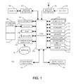
- FIG. 1 is a simplified block diagram of components including internal components of a portable electronic device according to an example embodiment
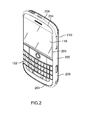
- FIG. 2 is a perspective view of an example of a portable electronic device
- FIG. 3 is an exploded view of portions of the portable electronic device of FIG. 2 , in accordance with an example embodiment
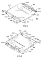
- FIG. 4 is a rear perspective view of a support tray of the portable electronic device of FIG. 2 ;
- FIG. 5 is a front perspective view of the support tray of the portable electronic device of FIG. 2 ;
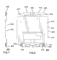
- FIG. 6 is a top view of the support tray of the portable electronic device of FIG. 2 ;
- FIG. 7 is side view of the support tray of the portable electronic device of FIG. 2 .
- the following describes electronic device includes a housing, a touch-sensitive display exposed by the housing, a support tray disposed between the touch-sensitive display and a base within the housing and supporting the touch-sensitive display on a first side thereof, the support tray including at least one pivot projecting from a second side of support tray, on which the support tray is pivotable, and an actuator disposed between the base and the support tray and actuatable by pivoting the support tray.
- a support tray that is pivotable on a pivot extending from one side, and an actuator that is actuatable by pivoting of the support tray, tactile feedback is provided upon depression of the touch-sensitive display.
- the pivotable support tray is constrained within the housing and constrains the touch-sensitive display to control movement of the touch-sensitive display, facilitating improved sealing and providing desirable tactile feedback.
- FIG. 1 shows a simplified block diagram of components including internal components of an electronic device according to an example embodiment.
- the portable electronic device in the example embodiments herein describe a portable electronic device, other electronic devices are contemplated.
- the portable electronic device in the present example 100 includes multiple components such as a processor 102 that controls the operations of the portable electronic device 100.
- Communication functions, including data and voice communications, are performed through a communication subsystem 104.
- Data received by the portable electronic device 100 is decompressed and decrypted by a decoder 106.
- the communication subsystem 104 receives messages from and sends messages to a wireless network 150.
- the wireless network 150 may be any type of wireless network, including, but not limited to, data-centric wireless networks, voice-centric wireless networks, and dual-mode networks that support both voice and data communications over the same physical base stations.
- the portable electronic device 100 is a battery-powered device and includes a battery interface 142 for receiving one or more rechargeable batteries 144.
- the processor 102 also interacts with additional subsystems such as a Random Access Memory (RAM) 108, a flash memory 110, a display 112 with a touch-sensitive overlay 114 connected to an electronic controller 116 that together comprise a touch-sensitive display 118, an actuator 120, a keyboard 122, an auxiliary input/output (I/O) subsystem 124, a data port 126, a speaker 128, a microphone 130, short-range communications 132 and other device subsystems 134.
- RAM Random Access Memory
- flash memory 110 a flash memory 110
- I/O auxiliary input/output subsystem
- data port 126 a data port 126
- speaker 128 a speaker
- microphone 130 short-range communications 132 and other device subsystems 134.
- User-interaction with the graphical user interface is performed through the touch-sensitive overlay 114.
- the processor 102 is electronically connected and interacts with the touch-sensitive overlay 114 via the electronic controller 116.
- the processor 102 may also interact with an accelerometer 136.
- the accelerometer 136 may include a cantilever beam with a proof mass and suitable deflection sensing circuitry.
- the accelerometer 136 may be utilized for detecting direction of gravitational forces or gravity-induced reaction forces.
- the portable electronic device 100 uses a Subscriber Identity Module or a Removable User Identity Module (SIM/RUIM) card 138 inserted into a SIM/RUIM interface 140 for communication with a network such as the wireless network 150.
- SIM/RUIM Removable User Identity Module
- user identification information may be programmed into the flash memory 110.
- the portable electronic device 100 also includes an operating system 146 and software components 148 that are executed by the processor 102 and are typically stored in a persistent store such as the flash memory 110. Additional applications may be loaded onto the portable electronic device 100 through the wireless network 150, the auxiliary I/O subsystem 124, the data port 126, the short-range communications subsystem 132, or any other suitable device subsystem 134.
- a received signal such as a text message, an e-mail message, or web page download is processed by the communication subsystem 104 and input to the processor 102.
- the processor 102 then processes the received signal for output to the display 112 or alternatively to the auxiliary I/O subsystem 124.
- a subscriber may also compose data items, such as e-mail messages, for example, which may be transmitted over the wireless network 150 through the communication subsystem 104.
- voice communications the overall operation of the portable electronic device 100 is similar.
- the speaker 128 outputs audible information converted from electrical signals, and the microphone 130 converts audible information into electrical signals for processing.
- FIG. 2 is a perspective view of an example of a portable electronic device 100.
- the portable electronic device 100 includes a housing 202 that is suitable for housing the internal components shown in FIG. 1 .
- the housing 202 includes a front 204 with a frame 206 that frames the touch-sensitive display 118 for user-interaction with the touch-sensitive display 118, sidewalls 208, and a back 210.
- the touch-sensitive display 118 is available for user interaction through the opening defined the by frame 206 in the front 204 of the housing 202.
- the portable electronic device 100 of FIG. 2 also includes a physical keyboard 122 such that the processor 102 (shown in FIG. 1 ) interacts with the keyboard 122 and the housing 202 is constructed to accommodate the keys of the keyboard 122.
- the housing 202 houses internal components of the portable electronic device 100, including the internal components that are shown in FIG. 1 and described above.
- FIG. 3 is a rear exploded view of parts of the portable electronic device 100 with the touch-sensitive display 118 facing down.
- the touch-sensitive display 118 is supported on a support tray 302, shown above the touch-sensitive display 118 in the exploded view of FIG. 3 .
- a base 304 which in the present example is a printed circuit board, is disposed between the support tray 302 and the back 210 of the portable electronic device 100.
- the housing 202 includes screw bosses 306 that are integrally molded into the housing 202 to connect the back 210, utilizing suitable screws that extend through the base 304 and into the screw bosses 306.
- the screw bosses 306 may be located at any suitable location and, in the example shown, screw bosses 306 are disposed near respective corners of the housing 202.
- the base 304 is thereby fixed within the housing 202 and may be spaced from the back 210 by suitable spacers that form part of the back 210 or are inserted between the back 210 and the base 304.
- the guides 308 may also be integrally molded into the housing 202.
- the guides 308 extend inwardly to cooperate with notches in the support tray 302 to constrain and inhibit lateral movement while facilitating pivotal movement of the support tray 302.
- a rounded protuberance 424 is coupled to the support tray 302 to act as an abutment surface to actuate the actuator 120.
- the rounded protuberance 424 includes a back that mates with an aperture in a lower end of the support tray 302
- the support tray 302 includes a body 402 that includes a central portion 404, an upper portion 406, and a lower portion 408.
- the body 402 may be made of, for example, stamped sheet metal.
- the central portion 404 includes a generally flat plate 410 on one side of which the touch-sensitive display 118 which is supported.
- the plate 410 includes slots and cut-out sections to accommodate electrical connections to the touch-sensitive display 118.
- Sidewalls 412 extend generally perpendicularly from each of four edges of the plate 410, including a top and bottom end of the plate 410.
- the sidewalls 412 extend perpendicularly from the plate 410 to protect the edges of the touch-sensitive display 118 supported on a first side of the support tray 302.
- the upper portion 404 extends from a sidewall 412 at a top of the plate 410 and the lower portion 404 extends from a sidewall 412 at a bottom of the plate 410.
- the upper portion 404 includes a portion of the stamped metal plate, which is generally flat and is overmolded with plastic to accommodate, for example, connection of the speaker 128 (shown in FIG. 1 ) and couplings for the auxiliary I/O (shown in FIG. 1 ).
- the upper portion 404, including the overmolded plastic includes C-shaped notches 414 with a respective one of the notches 414 at each side edge of the upper portion 406.
- the notches 414 are sized and shaped to cooperate with the guides 308 such that the guides 308 are received in the notches 414 and inhibit lateral movement of the upper portion 406, thereby inhibiting lateral movement of the support tray 302.
- the edges of the upper portion are defined by the sidewall 412 at the top of the plate 410, the C-shaped notches 414 and a generally curved edge opposite the sidewall 412.
- the upper portion 404 also includes pivots 416 with a respective one of the pivots 416 adjacent each of the C-shaped notches 414.
- the pivots 416 are therefore near an upper end of the support tray 302 and extend from an opposite side of the support tray 302 as the touch-sensitive display 118.
- the pivots 416 are generally semi-cylindrically shaped and are formed of the overmolded plastic.
- the pivots 416 extend from the upper portion 404 at a second side of the support tray 302 and extend a distance that is greater than the distance that the sidewalls 412 extend from the plate 410 such that the pivots 416 abut the base 304 to facilitate pivoting of the support tray 302 about the pivots 416, relative to the base 304.
- the lower portion 408 extends from a sidewall 412 at a bottom of the plate 410 and includes two generally flat lengths 418 that are joined at a stepped center 420 such that the center is stepped closer to the base 304 than the flat lengths 418.
- the stepped center 420 includes an aperture therein to receive the rounded protuberance 424 (shown in FIG. 3 ).
- the rounded protuberance 424, and the actuator 120, are therefore near a lower end of the support tray 302, which is opposite the upper end of the support tray 302.
- a respective foot 422 extends from the end of each of the generally flat lengths 418.
- the feet 422 extend in the direction of the base 304 to limit movement or bending of the support tray 302 and the touch-sensitive display 118 during and after actuation of the actuator 120 ( FIG. 1 ).
- Suitable biasing elements may be utilized to bias the touch-sensitive display 118 toward the frame 206 of the housing 202, into a position in which the actuator 120 (shown in FIG. 1 ) is not actuated.
- the feet 422 may each include biasing elements 426 that bias the feet 422 away from the base 304.
- the support tray 302 is not fastened to the housing 202. Instead, the support tray 302 is pivotable and constrained within the housing 202 by the base 304, the guides 308, and the frame 206 of the housing 202.
- the touch-sensitive display 118 is available for user interaction through the opening defined the by frame 206 in the front 204 of the housing 202.
- Pads such as gel pads, may be disposed between the touch-sensitive display 118 and the backside of the frame 206 to bias the touch-sensitive display 118, to provide a seal around the touch-sensitive display 118, and/or to improve tactile feel for the user.
- the constrained touch-sensitive display 118 provides controlled movement and facilitates sealing of the touch-sensitive display 118 utilizing, for example, the gel pads.
- the actuator 120 may be any suitable actuator.
- the actuator 120 may be a mechanical actuator such as a dome switch that is actuated by imparting a force to depress the switch and is returned to the unactuated state, referred to as released, when the imparted force is removed.
- the actuator 120 is depressed by applying sufficient force to the touch-sensitive display 118 to overcome the actuation force of the actuator 120.
- the actuator 120 may be actuated by pressing anywhere on the touch-sensitive display 118, causing pivoting of the touch-sensitive display 118, about the pivot axis defined by the pivots 416.
- the actuator 120 provides additional input to the processor 102 as an electrical signal is sent to the processor upon actuation and/or when the actuator is released.
- the actuator also provides desirable tactile feedback through the support tray 302 and touch-sensitive display 118 such that tactile feedback is provided upon actuation and upon release.
- the actuator 120 may be utilized to provide confirmation of selection of a feature on the touch-sensitive display 118. For example, a touch at a position on the touch-sensitive display 118, that is associated with a selectable feature, may result in display of an indicator at the selectable feature. Selection of the feature to perform an associated function is achieved when the touch-sensitive display is depressed and the actuator 120 is actuated.
- tactile feedback is provided upon depression of the touch-sensitive display.
- the tactile feedback confirms receipt of input to the user.
- the tactile feedback provides a positive response and reduces the chance of input errors such as double entry, decreasing use time and increasing user-satisfaction.
- the pivotable support tray is constrained within the housing and constrains the touch-sensitive display.
- the constrained touch-sensitive display provides controlled movement, facilitating improved sealing of the touch-sensitive display with the housing, reducing ingress of, for example, dust, and improving tactile feedback.
Landscapes
- Engineering & Computer Science (AREA)
- Theoretical Computer Science (AREA)
- General Engineering & Computer Science (AREA)
- Human Computer Interaction (AREA)
- Physics & Mathematics (AREA)
- General Physics & Mathematics (AREA)
- Computer Hardware Design (AREA)
- Position Input By Displaying (AREA)
- Telephone Set Structure (AREA)
Abstract
Description
- The present disclosure relates to an electronic device including a touch-sensitive display and an actuator to provide feedback.
- Electronic devices, including portable electronic devices, have gained widespread use and may provide a variety of functions including, for example, telephonic, electronic text messaging and other personal information manager (PIM) application functions. Portable electronic devices can include several types of devices including mobile stations such as simple cellular phones, smart phones, Personal Digital Assistants (PDAs), and laptop computers.
- Devices such as PDAs or smart phones are generally intended for handheld use and ease of portability. Smaller devices are generally desirable for portability. Touch-sensitive devices constructed of a display, such as a liquid crystal display (LCD), with a touch-sensitive overlay are useful on such handheld devices as such handheld devices are small and are therefore limited in space available for user input and output devices. Further, the screen content on the touch-sensitive devices can be modified depending on the functions and operations being performed.
- Tactile feedback for such touch-sensitive input devices provides a positive confirmation of, for example, touch selection. The provision and control of tactile feedback in touch-sensitive devices is desirable.
- An electronic device includes a housing, a touch-sensitive display exposed by the housing, a support tray disposed between the touch-sensitive display and a base within the housing and supporting the touch-sensitive display on a first side thereof, the support tray including at least one pivot projecting from a second side of support tray, on which the support tray is pivotable, and an actuator disposed between the base and the support tray and actuatable by pivoting the support tray.
- Embodiments of the present disclosure will now be described, by way of example only, with reference to the attached Figures, wherein:
-
FIG. 1 is a simplified block diagram of components including internal components of a portable electronic device according to an example embodiment; -
FIG. 2 is a perspective view of an example of a portable electronic device; -
FIG. 3 is an exploded view of portions of the portable electronic device ofFIG. 2 , in accordance with an example embodiment; -
FIG. 4 is a rear perspective view of a support tray of the portable electronic device ofFIG. 2 ; -
FIG. 5 is a front perspective view of the support tray of the portable electronic device ofFIG. 2 ; -
FIG. 6 is a top view of the support tray of the portable electronic device ofFIG. 2 ; and -
FIG. 7 is side view of the support tray of the portable electronic device ofFIG. 2 . - The following describes electronic device includes a housing, a touch-sensitive display exposed by the housing, a support tray disposed between the touch-sensitive display and a base within the housing and supporting the touch-sensitive display on a first side thereof, the support tray including at least one pivot projecting from a second side of support tray, on which the support tray is pivotable, and an actuator disposed between the base and the support tray and actuatable by pivoting the support tray.
- It will be appreciated that for simplicity and clarity of illustration, where considered appropriate, reference numerals may be repeated among the figures to indicate corresponding or analogous elements. In addition, numerous specific details are set forth in order to provide a thorough understanding of the example embodiments described herein. However, it will be understood by those of ordinary skill in the art that the example embodiments described herein may be practiced without these specific details. In other instances, well-known methods, procedures and components have not been described in detail so as not to obscure the example embodiments described herein. Also, the description is not to be considered as limited to the scope of the example embodiments described herein.
- Utilizing a support tray that is pivotable on a pivot extending from one side, and an actuator that is actuatable by pivoting of the support tray, tactile feedback is provided upon depression of the touch-sensitive display. The pivotable support tray is constrained within the housing and constrains the touch-sensitive display to control movement of the touch-sensitive display, facilitating improved sealing and providing desirable tactile feedback.
-
FIG. 1 shows a simplified block diagram of components including internal components of an electronic device according to an example embodiment. Although the electronic device in the example embodiments herein describe a portable electronic device, other electronic devices are contemplated. The portable electronic device in the present example 100 includes multiple components such as aprocessor 102 that controls the operations of the portableelectronic device 100. Communication functions, including data and voice communications, are performed through acommunication subsystem 104. Data received by the portableelectronic device 100 is decompressed and decrypted by adecoder 106. Thecommunication subsystem 104 receives messages from and sends messages to awireless network 150. Thewireless network 150 may be any type of wireless network, including, but not limited to, data-centric wireless networks, voice-centric wireless networks, and dual-mode networks that support both voice and data communications over the same physical base stations. The portableelectronic device 100 is a battery-powered device and includes abattery interface 142 for receiving one or morerechargeable batteries 144. - The
processor 102 also interacts with additional subsystems such as a Random Access Memory (RAM) 108, aflash memory 110, a display 112 with a touch-sensitive overlay 114 connected to anelectronic controller 116 that together comprise a touch-sensitive display 118, anactuator 120, akeyboard 122, an auxiliary input/output (I/O)subsystem 124, adata port 126, aspeaker 128, amicrophone 130, short-range communications 132 andother device subsystems 134. User-interaction with the graphical user interface is performed through the touch-sensitive overlay 114. Theprocessor 102 is electronically connected and interacts with the touch-sensitive overlay 114 via theelectronic controller 116. Information, such as text, characters, symbols, images, icons, and other items that may be displayed or rendered on a portable electronic device, is displayed on the touch-sensitive display 118 via theprocessor 102. Theprocessor 102 may also interact with anaccelerometer 136. Theaccelerometer 136 may include a cantilever beam with a proof mass and suitable deflection sensing circuitry. Theaccelerometer 136 may be utilized for detecting direction of gravitational forces or gravity-induced reaction forces. - To identify a subscriber for network access according to the present embodiment, the portable
electronic device 100 uses a Subscriber Identity Module or a Removable User Identity Module (SIM/RUIM)card 138 inserted into a SIM/RUIM interface 140 for communication with a network such as thewireless network 150. Alternatively, user identification information may be programmed into theflash memory 110. - The portable
electronic device 100 also includes anoperating system 146 andsoftware components 148 that are executed by theprocessor 102 and are typically stored in a persistent store such as theflash memory 110. Additional applications may be loaded onto the portableelectronic device 100 through thewireless network 150, the auxiliary I/O subsystem 124, thedata port 126, the short-range communications subsystem 132, or any othersuitable device subsystem 134. - In use, a received signal such as a text message, an e-mail message, or web page download is processed by the
communication subsystem 104 and input to theprocessor 102. Theprocessor 102 then processes the received signal for output to the display 112 or alternatively to the auxiliary I/O subsystem 124. A subscriber may also compose data items, such as e-mail messages, for example, which may be transmitted over thewireless network 150 through thecommunication subsystem 104. For voice communications, the overall operation of the portableelectronic device 100 is similar. Thespeaker 128 outputs audible information converted from electrical signals, and themicrophone 130 converts audible information into electrical signals for processing. -
FIG. 2 is a perspective view of an example of a portableelectronic device 100. The portableelectronic device 100 includes ahousing 202 that is suitable for housing the internal components shown inFIG. 1 . Thehousing 202 includes afront 204 with aframe 206 that frames the touch-sensitive display 118 for user-interaction with the touch-sensitive display 118,sidewalls 208, and aback 210. The touch-sensitive display 118 is available for user interaction through the opening defined the byframe 206 in thefront 204 of thehousing 202. The portableelectronic device 100 ofFIG. 2 also includes aphysical keyboard 122 such that the processor 102 (shown inFIG. 1 ) interacts with thekeyboard 122 and thehousing 202 is constructed to accommodate the keys of thekeyboard 122. Thehousing 202 houses internal components of the portableelectronic device 100, including the internal components that are shown inFIG. 1 and described above. -
FIG. 3 is a rear exploded view of parts of the portableelectronic device 100 with the touch-sensitive display 118 facing down. The touch-sensitive display 118 is supported on asupport tray 302, shown above the touch-sensitive display 118 in the exploded view ofFIG. 3 . Abase 304, which in the present example is a printed circuit board, is disposed between thesupport tray 302 and theback 210 of the portableelectronic device 100. - In the example of
FIG. 3 , thehousing 202 includesscrew bosses 306 that are integrally molded into thehousing 202 to connect theback 210, utilizing suitable screws that extend through thebase 304 and into thescrew bosses 306. Thescrew bosses 306 may be located at any suitable location and, in the example shown,screw bosses 306 are disposed near respective corners of thehousing 202. Thebase 304 is thereby fixed within thehousing 202 and may be spaced from the back 210 by suitable spacers that form part of the back 210 or are inserted between the back 210 and thebase 304. - A pair of
guides 308, that include generally spherical ends, protrude inwardly from thescrew bosses 306 at the top corners of thehousing 202, toward a centerline of thehousing 202. Theguides 308 may also be integrally molded into thehousing 202. Theguides 308 extend inwardly to cooperate with notches in thesupport tray 302 to constrain and inhibit lateral movement while facilitating pivotal movement of thesupport tray 302. A rounded protuberance 424 is coupled to thesupport tray 302 to act as an abutment surface to actuate theactuator 120. The rounded protuberance 424 includes a back that mates with an aperture in a lower end of thesupport tray 302 - Referring now to
FIG. 4, FIG. 5 ,FIG. 6, and FIG. 7 , thesupport tray 302 includes abody 402 that includes acentral portion 404, anupper portion 406, and alower portion 408. For the purposes of providing a reference, the terms upper and lower as used herein refer to the relative position of features when the portable electronic device is held in the upright position based on the orientation of thekeyboard 122. Thebody 402 may be made of, for example, stamped sheet metal. Thecentral portion 404 includes a generallyflat plate 410 on one side of which the touch-sensitive display 118 which is supported. Theplate 410 includes slots and cut-out sections to accommodate electrical connections to the touch-sensitive display 118.Sidewalls 412 extend generally perpendicularly from each of four edges of theplate 410, including a top and bottom end of theplate 410. Thesidewalls 412 extend perpendicularly from theplate 410 to protect the edges of the touch-sensitive display 118 supported on a first side of thesupport tray 302. - The
upper portion 404 extends from asidewall 412 at a top of theplate 410 and thelower portion 404 extends from asidewall 412 at a bottom of theplate 410. Theupper portion 404 includes a portion of the stamped metal plate, which is generally flat and is overmolded with plastic to accommodate, for example, connection of the speaker 128 (shown inFIG. 1 ) and couplings for the auxiliary I/O (shown inFIG. 1 ). Theupper portion 404, including the overmolded plastic, includes C-shapednotches 414 with a respective one of thenotches 414 at each side edge of theupper portion 406. Thenotches 414 are sized and shaped to cooperate with theguides 308 such that theguides 308 are received in thenotches 414 and inhibit lateral movement of theupper portion 406, thereby inhibiting lateral movement of thesupport tray 302. The edges of the upper portion are defined by thesidewall 412 at the top of theplate 410, the C-shapednotches 414 and a generally curved edge opposite thesidewall 412. - The
upper portion 404 also includespivots 416 with a respective one of thepivots 416 adjacent each of the C-shapednotches 414. Thepivots 416 are therefore near an upper end of thesupport tray 302 and extend from an opposite side of thesupport tray 302 as the touch-sensitive display 118. In the example shown inFIG. 4 and FIG. 5 , thepivots 416 are generally semi-cylindrically shaped and are formed of the overmolded plastic. Thepivots 416 extend from theupper portion 404 at a second side of thesupport tray 302 and extend a distance that is greater than the distance that thesidewalls 412 extend from theplate 410 such that thepivots 416 abut the base 304 to facilitate pivoting of thesupport tray 302 about thepivots 416, relative to thebase 304. - The
lower portion 408 extends from asidewall 412 at a bottom of theplate 410 and includes two generallyflat lengths 418 that are joined at a steppedcenter 420 such that the center is stepped closer to the base 304 than theflat lengths 418. The steppedcenter 420 includes an aperture therein to receive the rounded protuberance 424 (shown inFIG. 3 ). The rounded protuberance 424, and theactuator 120, are therefore near a lower end of thesupport tray 302, which is opposite the upper end of thesupport tray 302. - A
respective foot 422 extends from the end of each of the generallyflat lengths 418. Thefeet 422 extend in the direction of the base 304 to limit movement or bending of thesupport tray 302 and the touch-sensitive display 118 during and after actuation of the actuator 120 (FIG. 1 ). - Suitable biasing elements may be utilized to bias the touch-
sensitive display 118 toward theframe 206 of thehousing 202, into a position in which the actuator 120 (shown inFIG. 1 ) is not actuated. For example, thefeet 422 may each include biasingelements 426 that bias thefeet 422 away from thebase 304. - In the example shown in the figures, the
support tray 302 is not fastened to thehousing 202. Instead, thesupport tray 302 is pivotable and constrained within thehousing 202 by thebase 304, theguides 308, and theframe 206 of thehousing 202. - As indicated above, the touch-
sensitive display 118 is available for user interaction through the opening defined the byframe 206 in thefront 204 of thehousing 202. Pads, such as gel pads, may be disposed between the touch-sensitive display 118 and the backside of theframe 206 to bias the touch-sensitive display 118, to provide a seal around the touch-sensitive display 118, and/or to improve tactile feel for the user. The constrained touch-sensitive display 118 provides controlled movement and facilitates sealing of the touch-sensitive display 118 utilizing, for example, the gel pads. - The
actuator 120 may be any suitable actuator. For example, theactuator 120 may be a mechanical actuator such as a dome switch that is actuated by imparting a force to depress the switch and is returned to the unactuated state, referred to as released, when the imparted force is removed. Theactuator 120 is depressed by applying sufficient force to the touch-sensitive display 118 to overcome the actuation force of theactuator 120. Theactuator 120 may be actuated by pressing anywhere on the touch-sensitive display 118, causing pivoting of the touch-sensitive display 118, about the pivot axis defined by thepivots 416. Theactuator 120 provides additional input to theprocessor 102 as an electrical signal is sent to the processor upon actuation and/or when the actuator is released. The actuator also provides desirable tactile feedback through thesupport tray 302 and touch-sensitive display 118 such that tactile feedback is provided upon actuation and upon release. - The
actuator 120 may be utilized to provide confirmation of selection of a feature on the touch-sensitive display 118. For example, a touch at a position on the touch-sensitive display 118, that is associated with a selectable feature, may result in display of an indicator at the selectable feature. Selection of the feature to perform an associated function is achieved when the touch-sensitive display is depressed and theactuator 120 is actuated. - Utilizing a support tray that is pivotable on a pivot that extends from one side of the support tray, and an actuator that is actuatable by pivoting of the support tray, tactile feedback is provided upon depression of the touch-sensitive display. The tactile feedback confirms receipt of input to the user. The tactile feedback provides a positive response and reduces the chance of input errors such as double entry, decreasing use time and increasing user-satisfaction. The pivotable support tray is constrained within the housing and constrains the touch-sensitive display. The constrained touch-sensitive display provides controlled movement, facilitating improved sealing of the touch-sensitive display with the housing, reducing ingress of, for example, dust, and improving tactile feedback.
- While the embodiments described herein are directed to particular implementations of the actuating assembly and the portable electronic device and the, it will be understood that modifications and variations may occur to those skilled in the art. All such modifications and variations are believed to be within the sphere and scope of the present disclosure.
Claims (15)
- An electronic device comprising:a housing;a touch-sensitive display exposed by the housing;a support tray disposed between the touch-sensitive display and a base within the housing and supporting the touch-sensitive display on a first side thereof, the support tray including at least one pivot projecting from a second side of support tray, on which the support tray is pivotable; andan actuator disposed between the base and the support tray and actuatable by pivoting the support tray.
- The electronic device according to claim 1, wherein the at least one pivot is located near a first end of the support tray.
- The electronic device according to claim 2, wherein the actuator is located near a second end of the support tray.
- The electronic device according to any of claims 1 to 3, wherein the at least one pivot comprises a pair of spaced apart pivots projecting from the second side of the support tray the second side opposite the first side.
- The electronic device according to any of claims 1 to 4, wherein the base comprises a printed circuit board.
- The electronic device according to any of claims 1 to 5, wherein the extent of movement of the second end during pivoting is constrained by the base.
- The electronic device according to any of claims 1 to 6, wherein the support plate includes a C-shaped notch at each of two opposing side edges of the support tray.
- The electronic device according to claim 7, wherein the notches are near a first end of the support tray.
- The electronic device according to claim 7, comprising guides projecting inwardly within the housing and received in the notches of the support tray.
- The electronic device according to claim 9, wherein the guides comprise semispherical ends that are received in the notches of the support tray.
- The electronic device according to claim 9 or 10, wherein the support tray pivots around the guides.
- The electronic device according to any of claims 9 to 11, wherein the guides constrain the support tray to inhibit lateral movement of the touch-sensitive display.
- The electronic device according to any of claims 9 to 12, wherein the guides project inwardly from a portion of the housing.
- The electronic device according to any of claims 9 to 13, wherein the guides project inwardly from screw bosses near respective corners of the housing.
- The electronic device according to any of claims 9 to 14, wherein the guides are integrally formed with the housing.
Priority Applications (2)
| Application Number | Priority Date | Filing Date | Title |
|---|---|---|---|
| EP10172557.0A EP2418566B1 (en) | 2010-08-11 | 2010-08-11 | Electronic device including pivotable touch-sensitive display providing haptic feedback |
| CA2745644A CA2745644C (en) | 2010-08-11 | 2011-07-07 | Electronic device including touch-sensitive display |
Applications Claiming Priority (1)
| Application Number | Priority Date | Filing Date | Title |
|---|---|---|---|
| EP10172557.0A EP2418566B1 (en) | 2010-08-11 | 2010-08-11 | Electronic device including pivotable touch-sensitive display providing haptic feedback |
Publications (2)
| Publication Number | Publication Date |
|---|---|
| EP2418566A1 true EP2418566A1 (en) | 2012-02-15 |
| EP2418566B1 EP2418566B1 (en) | 2018-07-04 |
Family
ID=43086087
Family Applications (1)
| Application Number | Title | Priority Date | Filing Date |
|---|---|---|---|
| EP10172557.0A Active EP2418566B1 (en) | 2010-08-11 | 2010-08-11 | Electronic device including pivotable touch-sensitive display providing haptic feedback |
Country Status (2)
| Country | Link |
|---|---|
| EP (1) | EP2418566B1 (en) |
| CA (1) | CA2745644C (en) |
Citations (4)
| Publication number | Priority date | Publication date | Assignee | Title |
|---|---|---|---|---|
| GB2402105A (en) * | 2003-05-30 | 2004-12-01 | Therefore Ltd | Data input method for a computing device |
| WO2008151863A1 (en) * | 2007-06-14 | 2008-12-18 | Nokia Corporation | Touchpad assembly with tactile feedback |
| US20090167722A1 (en) * | 2004-09-09 | 2009-07-02 | Coactive Technologies, Inc. | Touch-sensitive faceplate with tactile feedback |
| US20100156844A1 (en) * | 2008-12-23 | 2010-06-24 | Research In Motion Limited | Portable electronic device and method of control |
Family Cites Families (2)
| Publication number | Priority date | Publication date | Assignee | Title |
|---|---|---|---|---|
| US20050122315A1 (en) * | 2001-11-16 | 2005-06-09 | Martin Chalk | Communications device and supporting network |
| US20060181517A1 (en) * | 2005-02-11 | 2006-08-17 | Apple Computer, Inc. | Display actuator |
-
2010
- 2010-08-11 EP EP10172557.0A patent/EP2418566B1/en active Active
-
2011
- 2011-07-07 CA CA2745644A patent/CA2745644C/en active Active
Patent Citations (4)
| Publication number | Priority date | Publication date | Assignee | Title |
|---|---|---|---|---|
| GB2402105A (en) * | 2003-05-30 | 2004-12-01 | Therefore Ltd | Data input method for a computing device |
| US20090167722A1 (en) * | 2004-09-09 | 2009-07-02 | Coactive Technologies, Inc. | Touch-sensitive faceplate with tactile feedback |
| WO2008151863A1 (en) * | 2007-06-14 | 2008-12-18 | Nokia Corporation | Touchpad assembly with tactile feedback |
| US20100156844A1 (en) * | 2008-12-23 | 2010-06-24 | Research In Motion Limited | Portable electronic device and method of control |
Also Published As
| Publication number | Publication date |
|---|---|
| EP2418566B1 (en) | 2018-07-04 |
| CA2745644A1 (en) | 2012-02-11 |
| CA2745644C (en) | 2015-10-06 |
Similar Documents
| Publication | Publication Date | Title |
|---|---|---|
| KR101024002B1 (en) | Tactile touch screen for electronic devices | |
| US8320131B2 (en) | Actuator assembly and electronic device including same | |
| KR101035315B1 (en) | Touch-sensitive touch screen for electronic devices | |
| TWI360070B (en) | Tactile touchscreen for electronic device | |
| US20120038469A1 (en) | Actuator assembly and electronic device including same | |
| US20120086648A1 (en) | Portable electronic device including touch-sensitive display | |
| TWI410114B (en) | Tactile touchscreen for electronic device | |
| MX2008009860A (en) | Tactile touchscreen for electronic device. | |
| US8229511B2 (en) | Electronic device including touch-sensitive display | |
| CA2745602C (en) | Actuator assembly and electronic device including same | |
| EP2360899A2 (en) | Slidable electronic device including touch-sensitive display | |
| CA2745644C (en) | Electronic device including touch-sensitive display | |
| CA2783725C (en) | Electronic device including keypad with keys having a ridged surface profile | |
| KR101085243B1 (en) | Electronic device and tactile touch screen display | |
| EP2506117A1 (en) | Portable electronic device with display and feedback module | |
| CA2745667C (en) | Actuator assembly and electronic device including same | |
| EP2211252A1 (en) | Portable electronic device including tactile touch-sensitive display | |
| US20120249427A1 (en) | Portable electronic device with a display and a feedback module | |
| EP2439607A1 (en) | Portable electronic device including touch-sensitive display | |
| EP2693722B1 (en) | Hybrid keypad apparatus |
Legal Events
| Date | Code | Title | Description |
|---|---|---|---|
| 17P | Request for examination filed |
Effective date: 20100811 |
|
| AK | Designated contracting states |
Kind code of ref document: A1 Designated state(s): AL AT BE BG CH CY CZ DE DK EE ES FI FR GB GR HR HU IE IS IT LI LT LU LV MC MK MT NL NO PL PT RO SE SI SK SM TR |
|
| AX | Request for extension of the european patent |
Extension state: BA ME RS |
|
| PUAI | Public reference made under article 153(3) epc to a published international application that has entered the european phase |
Free format text: ORIGINAL CODE: 0009012 |
|
| RAP1 | Party data changed (applicant data changed or rights of an application transferred) |
Owner name: BLACKBERRY LIMITED |
|
| RAP1 | Party data changed (applicant data changed or rights of an application transferred) |
Owner name: BLACKBERRY LIMITED |
|
| STAA | Information on the status of an ep patent application or granted ep patent |
Free format text: STATUS: EXAMINATION IS IN PROGRESS |
|
| 17Q | First examination report despatched |
Effective date: 20170308 |
|
| REG | Reference to a national code |
Ref country code: DE Ref legal event code: R079 Ref document number: 602010051610 Country of ref document: DE Free format text: PREVIOUS MAIN CLASS: G06F0003041000 Ipc: G06F0003048800 |
|
| GRAP | Despatch of communication of intention to grant a patent |
Free format text: ORIGINAL CODE: EPIDOSNIGR1 |
|
| STAA | Information on the status of an ep patent application or granted ep patent |
Free format text: STATUS: GRANT OF PATENT IS INTENDED |
|
| RIC1 | Information provided on ipc code assigned before grant |
Ipc: G06F 3/01 20060101ALI20171220BHEP Ipc: G06F 3/0488 20130101AFI20171220BHEP Ipc: G06F 3/041 20060101ALI20171220BHEP Ipc: G06F 1/16 20060101ALI20171220BHEP Ipc: G06F 3/0338 20130101ALI20171220BHEP |
|
| INTG | Intention to grant announced |
Effective date: 20180123 |
|
| GRAS | Grant fee paid |
Free format text: ORIGINAL CODE: EPIDOSNIGR3 |
|
| GRAA | (expected) grant |
Free format text: ORIGINAL CODE: 0009210 |
|
| STAA | Information on the status of an ep patent application or granted ep patent |
Free format text: STATUS: THE PATENT HAS BEEN GRANTED |
|
| AK | Designated contracting states |
Kind code of ref document: B1 Designated state(s): AL AT BE BG CH CY CZ DE DK EE ES FI FR GB GR HR HU IE IS IT LI LT LU LV MC MK MT NL NO PL PT RO SE SI SK SM TR |
|
| REG | Reference to a national code |
Ref country code: GB Ref legal event code: FG4D |
|
| REG | Reference to a national code |
Ref country code: CH Ref legal event code: EP |
|
| REG | Reference to a national code |
Ref country code: AT Ref legal event code: REF Ref document number: 1015216 Country of ref document: AT Kind code of ref document: T Effective date: 20180715 |
|
| REG | Reference to a national code |
Ref country code: IE Ref legal event code: FG4D |
|
| REG | Reference to a national code |
Ref country code: DE Ref legal event code: R096 Ref document number: 602010051610 Country of ref document: DE |
|
| REG | Reference to a national code |
Ref country code: FR Ref legal event code: PLFP Year of fee payment: 9 |
|
| REG | Reference to a national code |
Ref country code: NL Ref legal event code: MP Effective date: 20180704 |
|
| REG | Reference to a national code |
Ref country code: LT Ref legal event code: MG4D |
|
| REG | Reference to a national code |
Ref country code: AT Ref legal event code: MK05 Ref document number: 1015216 Country of ref document: AT Kind code of ref document: T Effective date: 20180704 |
|
| PG25 | Lapsed in a contracting state [announced via postgrant information from national office to epo] |
Ref country code: NL Free format text: LAPSE BECAUSE OF FAILURE TO SUBMIT A TRANSLATION OF THE DESCRIPTION OR TO PAY THE FEE WITHIN THE PRESCRIBED TIME-LIMIT Effective date: 20180704 |
|
| PG25 | Lapsed in a contracting state [announced via postgrant information from national office to epo] |
Ref country code: CZ Free format text: LAPSE BECAUSE OF FAILURE TO SUBMIT A TRANSLATION OF THE DESCRIPTION OR TO PAY THE FEE WITHIN THE PRESCRIBED TIME-LIMIT Effective date: 20180704 Ref country code: LT Free format text: LAPSE BECAUSE OF FAILURE TO SUBMIT A TRANSLATION OF THE DESCRIPTION OR TO PAY THE FEE WITHIN THE PRESCRIBED TIME-LIMIT Effective date: 20180704 Ref country code: AT Free format text: LAPSE BECAUSE OF FAILURE TO SUBMIT A TRANSLATION OF THE DESCRIPTION OR TO PAY THE FEE WITHIN THE PRESCRIBED TIME-LIMIT Effective date: 20180704 Ref country code: SE Free format text: LAPSE BECAUSE OF FAILURE TO SUBMIT A TRANSLATION OF THE DESCRIPTION OR TO PAY THE FEE WITHIN THE PRESCRIBED TIME-LIMIT Effective date: 20180704 Ref country code: BG Free format text: LAPSE BECAUSE OF FAILURE TO SUBMIT A TRANSLATION OF THE DESCRIPTION OR TO PAY THE FEE WITHIN THE PRESCRIBED TIME-LIMIT Effective date: 20181004 Ref country code: IS Free format text: LAPSE BECAUSE OF FAILURE TO SUBMIT A TRANSLATION OF THE DESCRIPTION OR TO PAY THE FEE WITHIN THE PRESCRIBED TIME-LIMIT Effective date: 20181104 Ref country code: PL Free format text: LAPSE BECAUSE OF FAILURE TO SUBMIT A TRANSLATION OF THE DESCRIPTION OR TO PAY THE FEE WITHIN THE PRESCRIBED TIME-LIMIT Effective date: 20180704 Ref country code: NO Free format text: LAPSE BECAUSE OF FAILURE TO SUBMIT A TRANSLATION OF THE DESCRIPTION OR TO PAY THE FEE WITHIN THE PRESCRIBED TIME-LIMIT Effective date: 20181004 Ref country code: GR Free format text: LAPSE BECAUSE OF FAILURE TO SUBMIT A TRANSLATION OF THE DESCRIPTION OR TO PAY THE FEE WITHIN THE PRESCRIBED TIME-LIMIT Effective date: 20181005 Ref country code: FI Free format text: LAPSE BECAUSE OF FAILURE TO SUBMIT A TRANSLATION OF THE DESCRIPTION OR TO PAY THE FEE WITHIN THE PRESCRIBED TIME-LIMIT Effective date: 20180704 |
|
| REG | Reference to a national code |
Ref country code: CH Ref legal event code: PK Free format text: BERICHTIGUNGEN |
|
| RIC2 | Information provided on ipc code assigned after grant |
Ipc: G06F 1/16 20060101ALI20171220BHEP Ipc: G06F 3/01 20060101ALI20171220BHEP Ipc: G06F 3/0338 20130101ALI20171220BHEP Ipc: G06F 3/041 20060101ALI20171220BHEP Ipc: G06F 3/0488 20130101AFI20171220BHEP |
|
| PG25 | Lapsed in a contracting state [announced via postgrant information from national office to epo] |
Ref country code: HR Free format text: LAPSE BECAUSE OF FAILURE TO SUBMIT A TRANSLATION OF THE DESCRIPTION OR TO PAY THE FEE WITHIN THE PRESCRIBED TIME-LIMIT Effective date: 20180704 Ref country code: ES Free format text: LAPSE BECAUSE OF FAILURE TO SUBMIT A TRANSLATION OF THE DESCRIPTION OR TO PAY THE FEE WITHIN THE PRESCRIBED TIME-LIMIT Effective date: 20180704 Ref country code: AL Free format text: LAPSE BECAUSE OF FAILURE TO SUBMIT A TRANSLATION OF THE DESCRIPTION OR TO PAY THE FEE WITHIN THE PRESCRIBED TIME-LIMIT Effective date: 20180704 Ref country code: LV Free format text: LAPSE BECAUSE OF FAILURE TO SUBMIT A TRANSLATION OF THE DESCRIPTION OR TO PAY THE FEE WITHIN THE PRESCRIBED TIME-LIMIT Effective date: 20180704 |
|
| REG | Reference to a national code |
Ref country code: CH Ref legal event code: PL |
|
| REG | Reference to a national code |
Ref country code: DE Ref legal event code: R097 Ref document number: 602010051610 Country of ref document: DE |
|
| PG25 | Lapsed in a contracting state [announced via postgrant information from national office to epo] |
Ref country code: MC Free format text: LAPSE BECAUSE OF FAILURE TO SUBMIT A TRANSLATION OF THE DESCRIPTION OR TO PAY THE FEE WITHIN THE PRESCRIBED TIME-LIMIT Effective date: 20180704 Ref country code: EE Free format text: LAPSE BECAUSE OF FAILURE TO SUBMIT A TRANSLATION OF THE DESCRIPTION OR TO PAY THE FEE WITHIN THE PRESCRIBED TIME-LIMIT Effective date: 20180704 Ref country code: IT Free format text: LAPSE BECAUSE OF FAILURE TO SUBMIT A TRANSLATION OF THE DESCRIPTION OR TO PAY THE FEE WITHIN THE PRESCRIBED TIME-LIMIT Effective date: 20180704 Ref country code: LU Free format text: LAPSE BECAUSE OF NON-PAYMENT OF DUE FEES Effective date: 20180811 Ref country code: LI Free format text: LAPSE BECAUSE OF NON-PAYMENT OF DUE FEES Effective date: 20180831 Ref country code: RO Free format text: LAPSE BECAUSE OF FAILURE TO SUBMIT A TRANSLATION OF THE DESCRIPTION OR TO PAY THE FEE WITHIN THE PRESCRIBED TIME-LIMIT Effective date: 20180704 Ref country code: CH Free format text: LAPSE BECAUSE OF NON-PAYMENT OF DUE FEES Effective date: 20180831 |
|
| PLBE | No opposition filed within time limit |
Free format text: ORIGINAL CODE: 0009261 |
|
| REG | Reference to a national code |
Ref country code: BE Ref legal event code: MM Effective date: 20180831 |
|
| STAA | Information on the status of an ep patent application or granted ep patent |
Free format text: STATUS: NO OPPOSITION FILED WITHIN TIME LIMIT |
|
| REG | Reference to a national code |
Ref country code: IE Ref legal event code: MM4A |
|
| PG25 | Lapsed in a contracting state [announced via postgrant information from national office to epo] |
Ref country code: SM Free format text: LAPSE BECAUSE OF FAILURE TO SUBMIT A TRANSLATION OF THE DESCRIPTION OR TO PAY THE FEE WITHIN THE PRESCRIBED TIME-LIMIT Effective date: 20180704 Ref country code: SK Free format text: LAPSE BECAUSE OF FAILURE TO SUBMIT A TRANSLATION OF THE DESCRIPTION OR TO PAY THE FEE WITHIN THE PRESCRIBED TIME-LIMIT Effective date: 20180704 Ref country code: DK Free format text: LAPSE BECAUSE OF FAILURE TO SUBMIT A TRANSLATION OF THE DESCRIPTION OR TO PAY THE FEE WITHIN THE PRESCRIBED TIME-LIMIT Effective date: 20180704 |
|
| 26N | No opposition filed |
Effective date: 20190405 |
|
| PG25 | Lapsed in a contracting state [announced via postgrant information from national office to epo] |
Ref country code: IE Free format text: LAPSE BECAUSE OF NON-PAYMENT OF DUE FEES Effective date: 20180811 |
|
| PG25 | Lapsed in a contracting state [announced via postgrant information from national office to epo] |
Ref country code: SI Free format text: LAPSE BECAUSE OF FAILURE TO SUBMIT A TRANSLATION OF THE DESCRIPTION OR TO PAY THE FEE WITHIN THE PRESCRIBED TIME-LIMIT Effective date: 20180704 Ref country code: BE Free format text: LAPSE BECAUSE OF NON-PAYMENT OF DUE FEES Effective date: 20180831 |
|
| PG25 | Lapsed in a contracting state [announced via postgrant information from national office to epo] |
Ref country code: MT Free format text: LAPSE BECAUSE OF NON-PAYMENT OF DUE FEES Effective date: 20180811 |
|
| PG25 | Lapsed in a contracting state [announced via postgrant information from national office to epo] |
Ref country code: TR Free format text: LAPSE BECAUSE OF FAILURE TO SUBMIT A TRANSLATION OF THE DESCRIPTION OR TO PAY THE FEE WITHIN THE PRESCRIBED TIME-LIMIT Effective date: 20180704 |
|
| PG25 | Lapsed in a contracting state [announced via postgrant information from national office to epo] |
Ref country code: HU Free format text: LAPSE BECAUSE OF FAILURE TO SUBMIT A TRANSLATION OF THE DESCRIPTION OR TO PAY THE FEE WITHIN THE PRESCRIBED TIME-LIMIT; INVALID AB INITIO Effective date: 20100811 Ref country code: PT Free format text: LAPSE BECAUSE OF FAILURE TO SUBMIT A TRANSLATION OF THE DESCRIPTION OR TO PAY THE FEE WITHIN THE PRESCRIBED TIME-LIMIT Effective date: 20180704 |
|
| PG25 | Lapsed in a contracting state [announced via postgrant information from national office to epo] |
Ref country code: MK Free format text: LAPSE BECAUSE OF NON-PAYMENT OF DUE FEES Effective date: 20180704 Ref country code: CY Free format text: LAPSE BECAUSE OF FAILURE TO SUBMIT A TRANSLATION OF THE DESCRIPTION OR TO PAY THE FEE WITHIN THE PRESCRIBED TIME-LIMIT Effective date: 20180704 |
|
| REG | Reference to a national code |
Ref country code: DE Ref legal event code: R082 Ref document number: 602010051610 Country of ref document: DE Ref country code: DE Ref legal event code: R081 Ref document number: 602010051610 Country of ref document: DE Owner name: MALIKIE INNOVATIONS LTD., IE Free format text: FORMER OWNER: BLACKBERRY LIMITED, WATERLOO, ONTARIO, CA |
|
| PGFP | Annual fee paid to national office [announced via postgrant information from national office to epo] |
Ref country code: DE Payment date: 20250827 Year of fee payment: 16 |
|
| PGFP | Annual fee paid to national office [announced via postgrant information from national office to epo] |
Ref country code: GB Payment date: 20250826 Year of fee payment: 16 |
|
| PGFP | Annual fee paid to national office [announced via postgrant information from national office to epo] |
Ref country code: FR Payment date: 20250825 Year of fee payment: 16 |