-
The present invention relates to a method and to a unit for detecting the effective position of an opening device applied onto a sealed package.
-
As is known, many food products, such as fruit juice, pasteurized or UHT (ultra-high-temperature treated) milk, wine, tomato sauce, etc., are sold in packages made of sterilized packaging material.
-
A typical example of this type of package is the parallelepiped-shaped package for liquid or pourable food products known as Tetra Brik Aseptic (registered trademark), which is made by folding and sealing laminated strip packaging material.
-
A further typical example of package is the so-called "gable-top", which comprise a parallelepiped main body and a top end portion which is formed by two sloping walls joined at a top sealing strip.
-
The packaging material has a multilayer structure substantially comprising a base layer for stiffness and strength, which may, in turn, comprise a layer of fibrous material, e.g. paper, or of mineral-filled polypropylene material; and a number of layers of heat-seal plastic material, e.g. polyethylene film, covering both sides of the base layer.
-
In the case of aseptic packages for long-storage products, such as UHT milk, the packaging material also comprises a layer of gas- and light-barrier material, e.g. aluminium foil or ethyl vinyl alcohol (EVOH), which is superimposed on a layer of heat-seal plastic material, and is in turn covered with another layer of heat-seal plastic material forming the inner face of the package eventually contacting the food product.
-
As is known, packages of this sort are produced on fully automatic packaging machines, on which a continuous tube is formed from the web-fed packaging material; the web of packaging material is sterilized on the packaging machine, e.g. by applying a chemical sterilizing agent, such as a hydrogen peroxide solution, which, once sterilization is completed, is removed from the surfaces of the packaging material, e.g. evaporated by heating; and the web of packaging material so sterilized is maintained in a closed, sterile environment, and is folded and sealed longitudinally to form a vertical tube.
-
The tube is filled continuously downwards with the sterilized or sterile-processed food product, and is sealed and then cut along equally spaced cross sections to form pillow packs, which are then fed to a folding unit to form the finished, e.g. substantially parallelepiped-shaped packages.
-
Alternatively, the packaging material may be cut into blanks, which are formed into packages on forming spindles, and the packages are filled with the food product and sealed. One example of this type of package is the so-called "gable-top" package known by the trade name Tetra Rex (registered trademark).
-
To open the packages described above, various solutions of opening devices have been proposed.
-
A first solution of opening device comprises a patch defined by a small sheet of a heat-seal plastic material, and which is heat sealed over a respective hole on the side of the web eventually forming the inside of the package; and a pull-off tab applied to the opposite side of the packaging material and heat sealed to the patch. The tab and patch adhere to each other, so that, when the tab is pulled off, the portion of the patch heat sealed to it is also removed to uncover the hole.
-
Alternatively, a second solution comprises closable opening devices which are applied by injecting plastic material directly onto the holes of the web.
-
Finally, a third solution of opening device comprises a frame defining an opening and fitted about a pierceable or removable portion of the packaging material.
-
The pierceable portion of the package may be defined by a so-called "prelaminated" hole, i.e. a hole formed in the base layer only and covered by the other lamination layers, including the layer of gas-barrier material.
-
More precisely, the web is provided with a plurality of prelaminated holes in a packaging material factory and then fed to the packaging machine.
-
Opening devices may be applied either onto the top wall of already formed packages or moulded onto the web before that packages are formed.
-
In both the cases, it is of the utmost importance within the industry to accurately check that the opening device is correctly positioned relative to the top wall of the package.
-
In particular, with reference to the third solution of the opening device, it is of the utmost importance to check that opening device is fitted about the removable portion within a very strict tolerance.
-
To this purpose, it has been proposed to use a camera to visually inspect the effective position of the opening device relative to the removable portion.
-
Due to the fact that the camera is highly expensive and/or is highly sensible to the color of the opening device, it has been proposed to use a group of photocells to detect the effective position of the opening device relative to the position of the removable portion.
-
More precisely, it has been proposed to use:
- a first photocell emitting a first radiation along a first direction which is orthogonal to the travelling direction of the package; and
- a pair of second photocells, which emit respective second radiations parallel to the first direction.
-
As the package advances along the travelling direction, the first photocell detects the presence of the opening device while the second photocells detect the presence of a lateral side of the package.
-
The distance between the second radiations is less than the length of the lateral side of the package
-
In case the opening device is spaced from the removable portion by less than a threshold value, the first photocell detects the presence of the opening device at the same time that the second photocells detect the presence of the package.
-
On the contrary, in case the opening device is spaced from the removable portion by more than the threshold value, when the first photocell detects the presence of the opening device, one of the second photocell no longer detects the presence of the package.
-
The above described assembly of first and second photocells is only capable of detecting whether or not the opening device is spaced from the removable portion more than the threshold value along the travelling direction of the packages.
-
Furthermore, the accuracy of the detection carried out by the assembly of photocells is quite rough. For example, the minimum distance which can be detected between the effective position of the opening device and the removable portion is of about 5 mm.
-
A need is felt within the industry to measure the distance between the effective position of the opening device and the position of the removable portion.
-
A need is also felt within to industry to measure the distance between the effective position of the opening device and the position of the removable portion, both along the travelling direction and along a direction which is orthogonal to the travelling direction.
-
A need is finally felt within the industry to increase the sensibility in the detection of the effective position of the opening device relative to the removable portion.
-
It is an object of the present invention to provide a method for detecting the effective position of an opening device applied onto a sealed package, designed to meet at least one of the above-identified requirement.
-
According to the present invention, there is provided a method for detecting the effective position of an opening device applied onto a sealed package, as claimed in Claim 1.
-
The present invention also relates to a unit for detecting the effective position of an opening device applied onto a sealed package, as claimed in claim 8.
-
A preferred, non-limiting embodiment of the present invention will be described by way of example with reference to the accompanying drawings, in which:
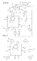
- Figure 1 is a frontal view of a first embodiment of a unit for detecting the effective position of an opening device applied onto a sealed package, according to the present invention;
- Figure 2 is a top view of the unit of Figure 1;
- Figure 3 is a frontal view of the first embodiment of the unit of Figure 1, in a set-up step;
- Figures 4 to 8 schematically show subsequent steps of a method for detecting the effective position of an opening device onto a package, according to the present invention;
- Figure 9 is an enlarged view of the top wall of a package processed by unit of Figures 1 to 3;
- Figures 10 and 11 schematically show the position of opening device during two different steps of the method according to the present invention;
- Figure 12 is a perspective view of a second embodiment of the unit of Figures 1 and 3; and
- Figure 13 is a perspective view of the second embodiment of the unit, in a set-up step.
-
Number 1 in Figure 1 indicates as a whole a unit for detecting the effective position of an opening device 2, which is applied onto a top wall 3 of a package 4.
-
Each package 4 is, in the embodiment shown in Figures 1 and 2, parallelepiped-shaped and sealed. As a result, top wall 3 is horizontal.
-
Packages 4 preferably contain a pourable food product, such as pasteurized or UHT milk, fruit juice, wine, etc.
-
Packages 4 may also contain a food product, which is pourable within a tube of packaging material when producing packages 4, and sets after packages 4 are sealed. One example of such a food product is a portion of cheese, which is melted when producing packages 4 and sets after packages 4 are sealed.
-
The tube is formed in known manner upstream from unit 1 by longitudinally folding and sealing a known web (not shown) of heat-seal sheet material, which comprises a layer of paper material covered on both sides with layers of heat-seal plastic material, e.g. polyethylene. In the case of an aseptic package 4 for long-storage products, such as UHT milk, the packaging material comprises a layer of oxygen-barrier material, e.g. aluminium foil, which is superimposed on one or more layers of heat-seal plastic material eventually forming the inner face of package 4 contacting the food product.
-
The tube of packaging material is then filled with the food product for packaging, and is sealed and cut along equally spaced cross sections to form a number of pillow packs (not shown), which are then transferred to a folding unit where they are folded mechanically to form respective packages 4.
-
In the embodiment shown, opening device 2 is fitted about a removable portion (not shown) of the packaging material.
-
The removable portion is defined by a so-called "pre-laminated" hole, i.e. a hole formed in the base layer only and covered by the lamination layers, including the layer of gas-barrier material.
-
Opening devices 2 are applied onto the top wall 3 of respective packages 4 downstream from the folding unit.
-
Alternatively, opening devices 2 are molded onto the web of sheet material before the folding of the tube and the subsequent formation of packages 4.
-
In both the cases, unit 1 is fed with packages 4 onto which respective opening devices 2 have been previously applied.
-
With particular reference to Figures 1 to 3, unit 1 substantially comprises:
- a linear conveyor 5 for advancing a sequence of packages 4 provided with respective opening devices 2 along a direction Y;
- a package transfer unit which comprises, for each package 4, a pair of cyclically movable bars 13, 15 (Figure 4) cooperating respectively with the rear and the frontal wall of relative package 4 to thrust it along direction Y;
- a fixed portal 6;
- a supporting structure 7a; and
- a pair of arms 7b which are adjustably connected to portal 6 and from which supporting structure 7a protrudes.
-
In detail, portal 6 comprises, in turn:
- a pair of substantially vertical lateral walls 9 which are spaced apart along a direction X which is orthogonal to direction Y;
- a substantially horizontal top wall 10 integral with and extending between walls 9, and arranged at least partially over conveyor 5; and
- a pair of substantially vertical sidewalls 11 which protrude from wall 10 on the opposite side of conveyor 5 and are parallel to each other.
-
Structure 7a comprises a plate 14 and a pair of appendices 16 which diverge from one another and protrudes from plate 14 on the opposite side of sidewalls 11.
-
Each arm 7b substantially extends along direction X and comprises:
- a first portion which is adjustably and releasably connected to relative sidewall 11; and
- a second portion which is releasably connected to a relative lateral side of plate 14.
-
Top wall 3 (figures 3 to 5) of each package 4 is bounded by a pair of opposite edges 8a, 8b parallel to each other, and by a pair of edges 8c, 8d parallel to each other and which extend orthogonally between edges 8a, 8b.
-
Edge 8c is arranged upstream from edge 8d, with reference to traveling direction of package 4 along direction Y.
-
As package 4 is advanced over conveyor 5 along direction Y, edges 8a, 8b are parallel to direction Y and edges 8c, 8d are parallel to direction X.
-
In the embodiment shown, the centre of opening device 2 is nearer to edge 8a than to edge 8b.
-
In figures 4 to 9, letter S indicates an outer profile of an opening device 2 which is arranged into the effective position.
-
Differently, letter T indicates an outer profile of an opening device 2 which is arranged in a theoretical reference position, in which it is fitted during a calibration step.
-
Unit 1 advantageously comprises:
- a sensor 20 which is adapted to detect, in use, the presence of opening device 2 along a direction A, which is associated to the theoretical position of opening device 2;
- a sensor 21 which is adapted to detect, in use, the presence of the opening device 2 along a direction B, which is associated to the theoretical position of opening device 2;
- a sensor 23 which is adapted to detect, in use, the presence of package 4 along a direction D, which is transversal to direction Y; and
- a control unit 25 (only schematically shown in Figure 6) configured for:
- generating a first parameter ΔT1 associated with a first time interval between a time t1, in which sensor 23 begins to detect the presence of package 4 along direction D, and a time t2, in which sensor 20 begins to detect the presence of opening device 2 along direction A;
- generating a second parameter ΔT2 associated with a second time interval between time t2 and a third time t3, in which sensor 21 begins to detect the presence of opening device 2 along direction B;
- generating a third parameter ΔTREF, associated to the speed VREF of package 4 along direction Y; and
- detecting, on the basis of at least two of the first, second and third parameter ΔT1, Δ2, ΔTREF, a distance ΔY measured along direction Y and a distance ΔX measured along direction X between corresponding points P, Q of opening device 2 arranged into effective and theoretical reference position.
-
Corresponding points P, Q are, in the present description, points P, Q of outer profiles S, T which define relative arches α, β of the same amplitude with relative fixed directions I, J, which are horizontal and parallel to direction Y in the embodiment shown (Figure 9).
-
In the embodiment shown, control unit 25 detects the distances ΔY, ΔX along respective directions Y, X between:
- point P of outer profile S to which direction A is tangent; and
- point Q of outer profile T to which direction A is tangent.
-
Unit 1 also comprises a sensor 22 which is adapted to detect, in use, the presence of package 4 along a direction C which is parallel to and staggered from direction D.
-
Direction D is, in the embodiment shown, arranged downstream from direction C, with reference to the advancing direction of package 4 along direction Y.
-
Accordingly, sensor 22 begins to detect opening device 2 at a time t0which is before times t1, t2 and t3. However, this is not necessary for carrying out the invention. Sensor 22 is used for establishing a reference time TREF or reference velocity VREF, which is calculated if a distance 1 (Figure 10) between the sensors 22, 23 is known. The reference velocity VREF can also be measured in other ways, not shown.
-
Directions A, B are tangent to outer profile T of opening device 2 when arranged in the theoretical reference position.
-
Directions C, D are orthogonal to direction Y and parallel to direction X.
-
In particular, directions A, B, D intersect each other in the same point O (Figure 6). However, this is not necessary for carrying out the invention.
-
Directions A and B are, in the embodiment shown, symmetrical to direction Y.
-
Furthermore, directions A, B are, in the embodiment shown, orthogonal to each other.
-
As a consequence, directions A, B define with directions Y and X angles each of 45 degrees.
-
Control unit 25 is functionally connected with sensors 20, 21, 22, 23 in order to generate the first, second and third parameter ΔT1, ΔT2, ΔTREF.
-
Furthermore, control unit 25 calculates:
- distance ΔX, on the basis of parameters ΔT2, ΔTREF only; and
- distance ΔY, on the basis of parameters ΔT1, ΔTREF and on the basis of a parameter OFFSET.
-
In particular, parameter OFFSET (Figure 10) equals the distance along direction Y between point Q of theoretical reference profile T and edge 8d. Parameter OFFSET is measured in a set-up or calibration step of unit 1.
-
In the embodiment shown, parameter ΔT1 coincides with the length of the interval between times t1 and t2, parameter ΔT2 coincides with the length of the interval between times t2 and t3, and parameter ΔTREF coincides with the inverse of the value of speed VREF.
-
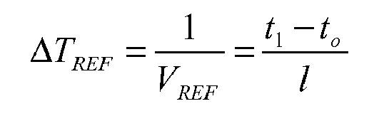
In particular, the parameter ΔTREF is evaluated on the basis of the distance 1 (figure 10) between directions C, D and the difference between times t0 and t1.
-
More precisely,
-
In other words, ΔTREF, equals the time taken by package 4 to move along a unitary distance.
-
Control unit 25 calculates ΔX on the basis of the following expression:
-
The above expressions may be justified, considering that, in case that distance ΔX is zero, time t2 coincides with time t3.
-
On the contrary, in case that distance ΔX is non-zero and that point P of profile S is closer to edge 8a than point Q of profile T, time t2 comes before time t3, and vice versa.
-
As shown in Figure 10, the distance covered from point P relative to point Q between times t2 and t3 equals 2*ΔY.
-
Therefore:
-
Due to the fact that directions A, B are orthogonal to each other and define an angle of 45 degrees with direction Y, ΔY and ΔX may be regarded as the catheti of an isosceles right-angled isosceles triangle (shown in
Figure 10). As a consequence ΔX is equal to ΔY and:
-
Furthermore,
control unit 25 calculates ΔY on the basis of the following expression:
-
The above expression may be explained in the following way.
-
In case that points P, Q of relative profiles S, T are spaced each other only along direction Y (Figure 11), t2 coincides with t3, and therefore ΔT2 equals to zero.
-
Accordingly, in this case, point P of profile S moves along direction Y of a length OFFSET+ΔY between times t1 and t2.
-
Therefore, in case that ΔX equals to zero:
-
However, if point P is spaced from Q also along direction X, for example if point P is closer than point Q to edge 8a, ΔX must be removed from ΔY.
-
Therefore:
-
Each sensor 20, 21, 22, 23 substantially comprises, in the embodiment shown:
- an emitter 30, 31, 32, 33 of an electromagnetic radiation, a laser radiation in the embodiment shown, along respective direction A, B, C, D;
- a receiver 40, 41, 42, 43 of the electromagnetic radiation emitted by emitter 30, 31, 32, 33 along direction A, B, C, D.
-
Emitters 30, 31 are carried by respective supports which downwards protrude from appendices 16 while receivers 40, 41 are carried by respective supports which downwards protrude from plate 14.
-
As it is arranged along direction A, B, opening device 2 interrupts the transmission of the electromagnetic radiation between emitter 30, 31 and corresponding receiver 40, 41 at times t2, t3.
-
In a complete analogous way, as it is arranged along direction C, D, a frontal wall 12 of package 4 interrupts the transmission of electromagnetic radiation between emitter 32, 33 and corresponding receiver 42, 43 respectively at times t0, t1.
-
In particular, edge 8d in common between walls 3, 12 of package 4.
-
The first portion of each arm 7b comprise two slots 35 which extend along direction X and each sidewall 11 comprise two slots 36 which extend along a direction Z, which is orthogonal to the plane defined by directions X, Y (Figures 1 and 3).
-
Each slot 36 is superimposed to a relative slot 35.
-
Furthermore, a pair of bolts 37 extend along direction Y, pass each through a relative slot 35 and a relative slot 36, and connect an arm 7b to a corresponding sidewall 11.
-
In this way, the position of arm 7b relative to corresponding sidewall 11 may be adjusted along directions X, Z, depending on the shape of package 4 and/or opening device 2 and on the position of opening device 2 onto wall 3.
-
Furthermore, the position of arm 7b relative to corresponding sidewall 11 may be adjusted along direction Y in a not-shown manner.
-
Furthermore, two bolts 38 connect the second portion of each arm 7b to a relative side of plate 14.
-
As shown in Figure 3, plate 14 comprises a through hole 50, which houses, in a set-up step of unit 1, a cylindrical bushing 51.
-
More precisely, through-hole 50 extends along an axis which is parallel to direction Z (Figure 3).
-
In the set-up or calibration step of unit 1, bushing 51 is fitted within hole 50, so that it protrudes downwards from plate 14.
-
Furthermore, it is selected a package 4 which has the respective opening device 2 arranged in the theoretical reference position, where such opening device 2 is normally located, if applied properly. However, since there is a deviation in the location of the prelaminated hole, a corresponding deviation should be detected in the location of opening device 2. A deviation from the theoretical reference position is hence not necessarily something bad.
-
Package 4 is advanced by package transfer unit, i.e. by corresponding bars 13, 15, up to it is below hole 50.
-
At this stage, the position of arms 7b is adjusted relative to sidewalls 11 along directions X, Z and, if necessary along direction Y, so that opening device 2 of selected package 4 is housed within bushing 51.
-
Due to the movement of arms 7b relative to sidewalls 11, sensors 20, 21 are automatically arranged in a position, in which, directions A, B are tangent to outer profile of opening device 2 of selected package 4, and therefore, to outer profile T.
-
At this stage, the distance between point Q and edge 8d along direction Y is known. The parameter OFFSET equals such a distance.
-
The set-up operation of unit 1 is completed and bushing 51 is removed from hole 50 (Figure 1).
-
The subsequent operation of unit 1 is described with reference to a single package 4 and to an opening device 2 applied on wall 3 of this package 4 in the effective position.
-
At first sensor 22 detects the passage of wall 12 of package 4 along direction C (Figure 4) at time t0.
-
Subsequently, sensor 23 detects the passage of wall 12 of package 4 along direction D at time t1 (Figure 5).
-
Control unit 25 evaluates the value of speed VREF of package 4, on the basis of distance 1 between sensors 22, 23 and of the length of interval between times to and t1.
-
In particular, control unit 25 evaluates the speed VREF of the package 4 as the ratio between 1 and t1 and t0, where 1 is the distance along direction Y between sensors 23, 22.
-
Control unit 25 also generates parameter ΔTREF which equals the difference between times t0 and t1, and, therefore, equals the time taken by package 4 to cover a unitary distance along direction Y.
-
Subsequently, outer profile S of opening device 2 is detected by sensor 20 at time t2 and by sensor 21 at time t3.
-
Control unit 25 generates parameter ΔT1 which equals the length of the interval between time t1 and t2, and parameter ΔT2 which equals the length of the interval between time t2 and t3
-
In case that point P of profile S is closer to edge 8a than point Q of profile T, time t2 comes before time t3, and vice versa.
-
In case that points P, Q are at the same distances from edge 8a, i.e. in case that ΔX equals zero, time t2 coincides with time t3.
-
In any case,
control unit 25 calculates ΔY and ΔX through the following expressions:
-
In case one or both the values ΔY, ΔX exceed relative threshold value, package 4 is discarded. Specifically, if the values ΔY, ΔX differ too much from the corresponding deviation for the prelaminated hole, the package 4 is discarded.
-
In case that a given number of packages 4 is discarded, the operation of unit 1 is terminated.
-
Number 1' in Figures 12 and 13 indicates a second embodiment of a unit in accordance with the present invention; unit 1, 1' being similar to each other, the following description is limited to the differences between them, and using the same references, where possible, for identical or corresponding parts.
-
Unit 1' differs from unit 1 in that the second portion of each arm 7b' is sloped relative to the relative first portion.
-
More precisely, second portion of each arm 7b' upwards projects from the corresponding second first and is, therefore, sloped relative to directions X and Y.
-
Second portion of each arm 7b' extends, therefore, at increasing distance from conveyor 5, proceeding from first portion of such arm 7b' on the opposite sides of sidewalls 11.
-
Furthermore, plate 14' differs from plate 14 in that it is sloped relative to the plane defined by direction X and Y.
-
More precisely, plate 14' extends substantially parallel to arms 7b'.
-
Unit 1' is adapted to detect the effective position of an opening device 2 applied onto a package 4' which is different from package 4.
-
More precisely, package 4' is a so-called "gable top package", which comprises a parallelepiped main body 60' and a top end portion 61' formed by two sloping walls 62', 63' joined at a sealing strip.
-
Opening device 2 is applied to wall 62'.
-
Top portion 61' also comprises two triangular lateral walls 64' interposed between walls 61', 62'.
-
The operation of unit 1' is substantially similar to the one of unit 1 and is not, therefore, described in detail.
-
The advantages of the method and of unit 1, 1' according to the present invention will be clear from the foregoing description.
-
In particular, unit 1, 1', differently from the photocells assembly described in the introductory part of the present description, detects the precise value of the distances ΔY, ΔX respectively along directions Y, X between the effective position of the opening device 2 and the theoretical reference position defined by outer profile T.
-
Furthermore, the Applicant has found that unit 1, 1" are capable of detecting very narrow distances ΔY, ΔX with respect to the photocells assembly described in the introductory part of the present description. For example, unit 1, 1' are capable of detecting distances ΔY, ΔX of about 1 mm, corresponding to very small displacements of the opening devices 2 from the reference position. This is particularly advantageous when opening devices 2 are fitted about a removable portion of the packaging material defined by a "so-called" pre-laminated hole.
-
Unit 1, 1' is also capable of detecting when opening device 2 has not been applied at all onto relative package 4.
-
Finally, the operation of unit 1, 1' is not affected by the color of opening device 2, which conversely may penalize the efficiency of visual system, like cameras.
-
In this case, the electromagnetic radiations emitted by emitters 30, 31 are not interrupted.
-
Clearly, changes may be made to unit 1, 1' and to the method without, however, departing from the protective scope defined in the accompanying Claims.