EP2418073A1 - A method of manufacturing an ophthalmic lens for providing an optical display - Google Patents
A method of manufacturing an ophthalmic lens for providing an optical display Download PDFInfo
- Publication number
- EP2418073A1 EP2418073A1 EP10305863A EP10305863A EP2418073A1 EP 2418073 A1 EP2418073 A1 EP 2418073A1 EP 10305863 A EP10305863 A EP 10305863A EP 10305863 A EP10305863 A EP 10305863A EP 2418073 A1 EP2418073 A1 EP 2418073A1
- Authority
- EP
- European Patent Office
- Prior art keywords
- lens
- mold
- entry surface
- cavity
- beam generator
- Prior art date
- Legal status (The legal status is an assumption and is not a legal conclusion. Google has not performed a legal analysis and makes no representation as to the accuracy of the status listed.)
- Granted
Links
Images

Classifications
-
- G—PHYSICS
- G02—OPTICS
- G02B—OPTICAL ELEMENTS, SYSTEMS OR APPARATUS
- G02B27/00—Optical systems or apparatus not provided for by any of the groups G02B1/00 - G02B26/00, G02B30/00
- G02B27/01—Head-up displays
- G02B27/017—Head mounted
-
- B—PERFORMING OPERATIONS; TRANSPORTING
- B29—WORKING OF PLASTICS; WORKING OF SUBSTANCES IN A PLASTIC STATE IN GENERAL
- B29C—SHAPING OR JOINING OF PLASTICS; SHAPING OF MATERIAL IN A PLASTIC STATE, NOT OTHERWISE PROVIDED FOR; AFTER-TREATMENT OF THE SHAPED PRODUCTS, e.g. REPAIRING
- B29C45/00—Injection moulding, i.e. forcing the required volume of moulding material through a nozzle into a closed mould; Apparatus therefor
- B29C45/14—Injection moulding, i.e. forcing the required volume of moulding material through a nozzle into a closed mould; Apparatus therefor incorporating preformed parts or layers, e.g. injection moulding around inserts or for coating articles
- B29C45/14065—Positioning or centering articles in the mould
-
- B—PERFORMING OPERATIONS; TRANSPORTING
- B29—WORKING OF PLASTICS; WORKING OF SUBSTANCES IN A PLASTIC STATE IN GENERAL
- B29D—PRODUCING PARTICULAR ARTICLES FROM PLASTICS OR FROM SUBSTANCES IN A PLASTIC STATE
- B29D11/00—Producing optical elements, e.g. lenses or prisms
- B29D11/00663—Production of light guides
- B29D11/00692—Production of light guides combined with lenses
-
- G—PHYSICS
- G02—OPTICS
- G02B—OPTICAL ELEMENTS, SYSTEMS OR APPARATUS
- G02B27/00—Optical systems or apparatus not provided for by any of the groups G02B1/00 - G02B26/00, G02B30/00
- G02B27/01—Head-up displays
- G02B27/017—Head mounted
- G02B27/0172—Head mounted characterised by optical features
-
- G—PHYSICS
- G02—OPTICS
- G02C—SPECTACLES; SUNGLASSES OR GOGGLES INSOFAR AS THEY HAVE THE SAME FEATURES AS SPECTACLES; CONTACT LENSES
- G02C7/00—Optical parts
- G02C7/02—Lenses; Lens systems ; Methods of designing lenses
- G02C7/08—Auxiliary lenses; Arrangements for varying focal length
- G02C7/086—Auxiliary lenses located directly on a main spectacle lens or in the immediate vicinity of main spectacles
-
- B—PERFORMING OPERATIONS; TRANSPORTING
- B29—WORKING OF PLASTICS; WORKING OF SUBSTANCES IN A PLASTIC STATE IN GENERAL
- B29L—INDEXING SCHEME ASSOCIATED WITH SUBCLASS B29C, RELATING TO PARTICULAR ARTICLES
- B29L2011/00—Optical elements, e.g. lenses, prisms
- B29L2011/0016—Lenses
-
- B—PERFORMING OPERATIONS; TRANSPORTING
- B29—WORKING OF PLASTICS; WORKING OF SUBSTANCES IN A PLASTIC STATE IN GENERAL
- B29L—INDEXING SCHEME ASSOCIATED WITH SUBCLASS B29C, RELATING TO PARTICULAR ARTICLES
- B29L2011/00—Optical elements, e.g. lenses, prisms
- B29L2011/0075—Light guides, optical cables
-
- G—PHYSICS
- G02—OPTICS
- G02B—OPTICAL ELEMENTS, SYSTEMS OR APPARATUS
- G02B27/00—Optical systems or apparatus not provided for by any of the groups G02B1/00 - G02B26/00, G02B30/00
- G02B27/01—Head-up displays
- G02B27/0101—Head-up displays characterised by optical features
- G02B2027/011—Head-up displays characterised by optical features comprising device for correcting geometrical aberrations, distortion
Definitions
- the present invention relates to a method of manufacturing an ophthalmic lens for making an optical display by means of an optical imager designed to allow information of the image or multimedia type to be viewed.
- the term "lens” is used herein to designate an optical system suitable in particular for being positioned in a frame for spectacles or eyeglasses.
- lens is used to mean a finished lens ready for placing on a spectacles frame, or an unfinished lens or lens blank, i.e. that still needs to be subjected to at least one treatment, e.g. surfacing, in order to be usable.
- the document WO 2006/016086 discloses a method of manufacturing a vision-correction lens 1 as represented in figure 1 , that has a front face 1A and a rear face 1B, and into which light beams coming from a micro display 5 and emitted by an optical element of a light beam generator system 2 are introduced via an entry surface 3 and directed towards the eye of the wearer to enable information content to be viewed.
- the light beams are reflected a plurality of times between two reflection faces, between being introduced into the lens and exiting therefrom, these two reflection faces being faces of a transparent optical insert constituted by a light guide 4.
- the insert 4 is completely contained within the lens 1.
- the vision of a user can be corrected, while being mass-produced in reliable manner, with this being achieved by decoupling the display and the vision-correction functions.
- the entry surface 3 is formed by making a molded cavity in the lens, and it constitutes the bottom of the cavity.
- the cavity is molded by means of a stud secured to a mold portion, and the insert 4 is temporarily secured to this stud prior to molding. Once the lens is manufactured, the light beam generator system 2 is then placed on this entry surface 3.
- the first beam generator piece 2A is placed and stuck on the rear face of the light guide 4 and the second beam generator piece 2B is placed and stuck on the front face of the light guide 4.
- Such arrangement results in a beam generator system having a smaller volume and a repartition around the lens.
- the object of the invention is to propose a method of manufacturing an ophthalmic lens relating to this arrangement with two beam generator pieces.
- the invention proposes a method of manufacturing a vision-correction lens, that has a front face and a rear face, and into which light beams emitted by an optical element of a light beam generator system are introduced and directed towards the eye of the wearer to enable information content to be viewed by means of a transparent light guide, said light beam generator system being constituted by two optical pieces, a first beam generator piece placed on a first entry surface of the rear face of the lens and a second optical piece placed on a second entry surface of the front face of the lens, method consisting in molding the lens in a mold formed by a first mold portion and a second mold portion, the space between these two portions being closed by a cylindrical element, and characterized in that
- the invention concerns a method of manufacturing a vision-correction lens 1, that has a front face 1A and a rear face 1B, and into which light beams emitted by an optical element of a light beam generator system 2A, 2B are introduced and directed towards the eye of the wearer to enable information content to be viewed by means of a transparent light guide 4.
- the light beam generator system is constituted by two optical pieces, a first beam generator piece 2A placed on a first entry surface 4A of the rear face of the lens and a second optical piece 2B placed on a second entry surface 4B of the front face of the lens.
- the mold for manufacturing the lens essentially comprises a mold comprising two mold portions, a first mold portion 6A for molding the front face of the blank lens, and a second mold portion 6B for molding the rear face of the blank lens, the space between these two portions being closed by a cylindrical element 7.
- the method consists in molding the lens 1 between this first mold portion 6A and this second mold portion 6B.
- the first entry surface 4A is formed by making in the lens a molded cavity by means of a stud 6C secured to the second mold portion 6B, and the light guide 4 is temporarily secured to the stud 6C prior to molding.
- the second entry surface 4B is formed by making in the lens a molded cavity by means of a mold part comprising a peripheric cylindrical element 7, the first mold portion 6A being placed above this lateral cylindrical element 7 and the space between the first mold portion 6A and the second mold portion 6B being closed by this lateral cylindrical element 7.
- the first entry surface 4A through which the light beams emitted by the optical element of the first light beam generation piece 2A are introduced is formed by making a molded cavity in the lens, with the surface constituting the bottom of the cavity.
- This cavity is molded by means of the stud 6C secured to the second mold portion 6B, and preferably integral therewith, and the light guide 4 is secured temporarily on the stud by adhesive prior to molding.
- the stud 6C is placed on a side edge of the second portion 6B.
- the surface of the stud 6C that is to receive the light guide 4 is coated with adhesive, advantageously MR8UV, and the light guide is positioned on the stud 6C by an appropriate tool as a function of the marking provided on the mold.
- the light guide is pressed against a stud and held until the adhesive has polymerized.
- MR8UV adhesive
- the light guide 4 is secured temporarily to the stud 6C prior to molding by means of a layer of the monomer constituting the lens 1.
- the thin layer of monomer serving to bond the light guide then acts after unmolding as a thin layer covering the light guide at the entry surface 4A and presenting the same refractive index as the remainder of the lens 4.
- the mold portions 6A, 6B may be made of metal, e.g. of X15 steel coated with a TiCN treatment to allow disassembly.
- thermoplastic organic material preferably of a material that does not adhere to the monomer resin used, e.g. polypropylene or TPX.
- They may be of inorganic material with a coating constituted for example by a top coat or by an unmolding agent that can be added to the polymerizable resin constituting the lens 1.
- the used monomer for molding the lens 1 may be MR6.
- the two mold portions 6A or 6B may be plane or curved depending on whether it is desired to manufacture a finished lens ready for positioning in a frame, or a lens blank as illustrated, i.e. that needs to be subjected to at least one further treatment, e.g. surfacing, in order to be usable.
- the second entry surface 4B is formed by making in the lens a second cavity by adequate partial filling of the mold with monomer in order to form an air volume 8 and by adequate inclination of the mold, in order to form the second cavity with the air volume 8.
- the mold can be filled in vertical position and then be inclined or it can be filled directly in inclined position.
- the monomer is polymerized by heating in the mold and a blank lens is obtained which after surfacing of the faces of this blank lens gives a lens 1 as represented in figure 5B where it can be equipped with the first and second beam generator pieces 2A, 2B.
- the quantity of monomer introduced in the mold and the angle of inclination are defined preferably by tests, and depend on the wished dimensions of the mold, of the light guide 4 and of the second entry surface 4B.
- this inclination presents an angle equal to 70 to 80 degrees relating to a horizontal plane and the mold is filled with a rate of 75 to 85% taking into consideration the volume retraction of the monomer which can be of around 8%.
- air is used in order to form the complementary volume 8 forming the second cavity.
- the volume is filled with a component immiscible and chemically inert during molding with the molded product constituting the lens, which is preferably a monomer.
- this component is a gas but it can be a liquid, which is removed after the molding and the casting of the monomer constituting the lens.
- the liquid can be less heavy than the molded product constituting the lens and the method of manufacturing is unchanged, as described here above, the complementary volume 8 being in the upside of the inclined mold.
- the liquid can be heavier than the molded product constituting the lens too and the complementary volume 8 is in the downside of the inclined mold, the mold being turned by 180° relating to the arrangement described here above.
Landscapes
- Physics & Mathematics (AREA)
- Engineering & Computer Science (AREA)
- Health & Medical Sciences (AREA)
- Ophthalmology & Optometry (AREA)
- General Physics & Mathematics (AREA)
- Optics & Photonics (AREA)
- Manufacturing & Machinery (AREA)
- Mechanical Engineering (AREA)
- General Health & Medical Sciences (AREA)
- Casting Or Compression Moulding Of Plastics Or The Like (AREA)
- Moulds For Moulding Plastics Or The Like (AREA)
Abstract
- the first entry surface (4A) is formed by making in the lens a first molded cavity by means of a stud (6C) secured to the second mold portion (6B), and that the light guide (4) is temporarily secured to said stud (6C) prior to molding;
- the second entry surface (4B) is formed by making in the lens a second cavity by adequate partial filling of the mold in order to form an complementary volume (8) forming said second cavity and filled with a component immiscible and chemically inert during molding with the molded product constituting the lens.
Description
- The present invention relates to a method of manufacturing an ophthalmic lens for making an optical display by means of an optical imager designed to allow information of the image or multimedia type to be viewed. The term "lens" is used herein to designate an optical system suitable in particular for being positioned in a frame for spectacles or eyeglasses.
- This term "lens" is used to mean a finished lens ready for placing on a spectacles frame, or an unfinished lens or lens blank, i.e. that still needs to be subjected to at least one treatment, e.g. surfacing, in order to be usable.
- The document
WO 2006/016086 discloses a method of manufacturing a vision-correction lens 1 as represented infigure 1 , that has afront face 1A and arear face 1B, and into which light beams coming from amicro display 5 and emitted by an optical element of a lightbeam generator system 2 are introduced via anentry surface 3 and directed towards the eye of the wearer to enable information content to be viewed. The light beams are reflected a plurality of times between two reflection faces, between being introduced into the lens and exiting therefrom, these two reflection faces being faces of a transparent optical insert constituted by alight guide 4. According to this known method, theinsert 4 is completely contained within thelens 1. - With this method of manufacturing an ophthalmic display, the vision of a user can be corrected, while being mass-produced in reliable manner, with this being achieved by decoupling the display and the vision-correction functions.
- The
entry surface 3 is formed by making a molded cavity in the lens, and it constitutes the bottom of the cavity. The cavity is molded by means of a stud secured to a mold portion, and theinsert 4 is temporarily secured to this stud prior to molding. Once the lens is manufactured, the lightbeam generator system 2 is then placed on thisentry surface 3. - Other solutions propose such lens for making an optical display with complex light beam generator system formed by two beam generator pieces as represented in
figure 2 . - The first
beam generator piece 2A is placed and stuck on the rear face of thelight guide 4 and the secondbeam generator piece 2B is placed and stuck on the front face of thelight guide 4. Such arrangement results in a beam generator system having a smaller volume and a repartition around the lens. - The object of the invention is to propose a method of manufacturing an ophthalmic lens relating to this arrangement with two beam generator pieces.
- The invention proposes a method of manufacturing a vision-correction lens, that has a front face and a rear face, and into which light beams emitted by an optical element of a light beam generator system are introduced and directed towards the eye of the wearer to enable information content to be viewed by means of a transparent light guide, said light beam generator system being constituted by two optical pieces, a first beam generator piece placed on a first entry surface of the rear face of the lens and a second optical piece placed on a second entry surface of the front face of the lens, method consisting in molding the lens in a mold formed by a first mold portion and a second mold portion, the space between these two portions being closed by a cylindrical element, and characterized in that
- the first entry surface is formed by making in the lens a first molded cavity by means of a stud secured to the second mold portion, and that the light guide is temporarily secured to said stud prior to molding;
- the second entry surface is formed by making in the lens a second cavity by adequate partial filling of the mold in order to form an complementary volume forming said second cavity and filled with a component immiscible and chemically inert during molding with the molded product constituting the lens.
- The invention is described with below in greater detail with the help of figures that show merely a preferred embodiment of the invention.
-
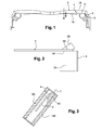
Figure 1 is a section view of a display including a lens, according to first prior art. -
Figure 2 is a section view of a display including a lens, according to second prior art. -
Figure 3 is a section view showing the method in accordance with the invention for manufacturing the lens according to second prior art. -
Figures 4A and 4B are perspective views showing the method in accordance with the invention for manufacturing the lens according to second prior art. -
Figures 5A and 5B are perspective and lateral views of a lens obtained by means of the method in accordance with the invention. - As represented in
figure 2 , the invention concerns a method of manufacturing a vision-correction lens 1, that has afront face 1A and arear face 1B, and into which light beams emitted by an optical element of a lightbeam generator system transparent light guide 4. The light beam generator system is constituted by two optical pieces, a firstbeam generator piece 2A placed on afirst entry surface 4A of the rear face of the lens and a secondoptical piece 2B placed on asecond entry surface 4B of the front face of the lens. - As represented in
figures 3 to 5 , the mold for manufacturing the lens essentially comprises a mold comprising two mold portions, afirst mold portion 6A for molding the front face of the blank lens, and asecond mold portion 6B for molding the rear face of the blank lens, the space between these two portions being closed by a cylindrical element 7. - The method consists in molding the
lens 1 between thisfirst mold portion 6A and thissecond mold portion 6B. - The
first entry surface 4A is formed by making in the lens a molded cavity by means of astud 6C secured to thesecond mold portion 6B, and thelight guide 4 is temporarily secured to thestud 6C prior to molding. - The
second entry surface 4B is formed by making in the lens a molded cavity by means of a mold part comprising a peripheric cylindrical element 7, thefirst mold portion 6A being placed above this lateral cylindrical element 7 and the space between thefirst mold portion 6A and thesecond mold portion 6B being closed by this lateral cylindrical element 7. - The
first entry surface 4A through which the light beams emitted by the optical element of the first lightbeam generation piece 2A are introduced is formed by making a molded cavity in the lens, with the surface constituting the bottom of the cavity. - This cavity is molded by means of the
stud 6C secured to thesecond mold portion 6B, and preferably integral therewith, and thelight guide 4 is secured temporarily on the stud by adhesive prior to molding. Thestud 6C is placed on a side edge of thesecond portion 6B. - The surface of the
stud 6C that is to receive thelight guide 4 is coated with adhesive, advantageously MR8UV, and the light guide is positioned on thestud 6C by an appropriate tool as a function of the marking provided on the mold. The light guide is pressed against a stud and held until the adhesive has polymerized. When using MR8, it is initiated with a particular photoinitiator that enables polymerization to take place quickly under UV radiation. - Most advantageously, the
light guide 4 is secured temporarily to thestud 6C prior to molding by means of a layer of the monomer constituting thelens 1. As a result, the thin layer of monomer serving to bond the light guide then acts after unmolding as a thin layer covering the light guide at theentry surface 4A and presenting the same refractive index as the remainder of thelens 4. - The
mold portions - They may be of thermoplastic organic material, preferably of a material that does not adhere to the monomer resin used, e.g. polypropylene or TPX.
- They may be of inorganic material with a coating constituted for example by a top coat or by an unmolding agent that can be added to the polymerizable resin constituting the
lens 1. - By way of example, the used monomer for molding the
lens 1 may be MR6. - The two
mold portions - According to the invention, the
second entry surface 4B is formed by making in the lens a second cavity by adequate partial filling of the mold with monomer in order to form anair volume 8 and by adequate inclination of the mold, in order to form the second cavity with theair volume 8. - The mold can be filled in vertical position and then be inclined or it can be filled directly in inclined position.
- In the inclined position, the
stud 6C and theair volume 8 are placed together with a common plane of symmetry, in order to form the corresponding cavity in the blank lens represented infigure 5A , the monomer is polymerized by heating in the mold and a blank lens is obtained which after surfacing of the faces of this blank lens gives alens 1 as represented infigure 5B where it can be equipped with the first and secondbeam generator pieces - The quantity of monomer introduced in the mold and the angle of inclination are defined preferably by tests, and depend on the wished dimensions of the mold, of the
light guide 4 and of thesecond entry surface 4B. Preferably, this inclination presents an angle equal to 70 to 80 degrees relating to a horizontal plane and the mold is filled with a rate of 75 to 85% taking into consideration the volume retraction of the monomer which can be of around 8%. - According to the preferred embodiment of the invention, as described here above, air is used in order to form the
complementary volume 8 forming the second cavity. - More generally, the volume is filled with a component immiscible and chemically inert during molding with the molded product constituting the lens, which is preferably a monomer. Preferably, this component is a gas but it can be a liquid, which is removed after the molding and the casting of the monomer constituting the lens.
- In case of use of liquid, the liquid can be less heavy than the molded product constituting the lens and the method of manufacturing is unchanged, as described here above, the
complementary volume 8 being in the upside of the inclined mold. - The liquid can be heavier than the molded product constituting the lens too and the
complementary volume 8 is in the downside of the inclined mold, the mold being turned by 180° relating to the arrangement described here above.
Claims (5)
- A method of manufacturing a vision-correction lens (1), that has a front face (1A) and a rear face (1B), and into which light beams emitted by an optical element of a light beam generator system are introduced and directed towards the eye of the wearer to enable information content to be viewed by means of a transparent light guide (4), said light beam generator system being constituted by two optical pieces, a first beam generator piece (2A) placed on a first entry surface (4A) of the rear face of the lens and a second optical piece (2B) placed on a second entry surface (4B) of the front face of the lens, method consisting in molding the lens (1) in a mold formed by a first mold portion (6A) and a second mold portion (6B), the space between these two portions being closed by a cylindrical element, and characterized in that- the first entry surface (4A) is formed by making in the lens a first molded cavity by means of a stud (6C) secured to the second mold portion (6B), and that the light guide (4) is temporarily secured to said stud (6C) prior to molding;- the second entry surface (4B) is formed by making in the lens a second cavity by adequate partial filling of the mold in order to form an complementary volume (8) forming said second cavity and filled with a component immiscible and chemically inert during molding with the molded product constituting the lens.
- A method according to claim 1, characterized in that the second entry surface (4B) is formed by making in the lens said second molded cavity by adequate inclination of the mold, in order to form said second cavity with said complementary volume (8).
- A method according to one of preceding claims, characterized in that said stud (6C) and said complementary volume (8) are placed together with a common plan of symmetry.
- A method according to one of preceding claims, characterized in that said component is a gas.
- A method according to the preceding claim, characterized in that said component is air.
Priority Applications (1)
| Application Number | Priority Date | Filing Date | Title |
|---|---|---|---|
| EP20100305863 EP2418073B1 (en) | 2010-08-05 | 2010-08-05 | A method of manufacturing an ophthalmic lens for providing an optical display |
Applications Claiming Priority (1)
| Application Number | Priority Date | Filing Date | Title |
|---|---|---|---|
| EP20100305863 EP2418073B1 (en) | 2010-08-05 | 2010-08-05 | A method of manufacturing an ophthalmic lens for providing an optical display |
Publications (2)
| Publication Number | Publication Date |
|---|---|
| EP2418073A1 true EP2418073A1 (en) | 2012-02-15 |
| EP2418073B1 EP2418073B1 (en) | 2012-10-10 |
Family
ID=43067130
Family Applications (1)
| Application Number | Title | Priority Date | Filing Date |
|---|---|---|---|
| EP20100305863 Active EP2418073B1 (en) | 2010-08-05 | 2010-08-05 | A method of manufacturing an ophthalmic lens for providing an optical display |
Country Status (1)
| Country | Link |
|---|---|
| EP (1) | EP2418073B1 (en) |
Cited By (3)
| Publication number | Priority date | Publication date | Assignee | Title |
|---|---|---|---|---|
| WO2015011288A1 (en) * | 2013-07-26 | 2015-01-29 | Carl Zeiss Ag | Spectacle lens and display device comprising such a spectacle lens |
| WO2015140104A1 (en) * | 2014-03-18 | 2015-09-24 | Essilor International (Compagnie Générale d'Optique) | A mould and process for manufacturing an ophthalmic lens equipped with an insert |
| WO2015158831A1 (en) * | 2014-04-17 | 2015-10-22 | Carl Zeiss Smart Optics Gmbh | Eyeglass lens for a display device, which display device can be placed on the head of a user and produces an image |
Families Citing this family (2)
| Publication number | Priority date | Publication date | Assignee | Title |
|---|---|---|---|---|
| CN105980910B (en) * | 2014-03-18 | 2019-11-05 | 依视路国际公司 | Method for manufacturing an ophthalmic lens equipped with an insert |
| DE102022117022A1 (en) | 2022-07-07 | 2024-01-18 | Carl Zeiss Ag | Method for producing an optical arrangement comprising an optical waveguide and an optical component |
Citations (5)
| Publication number | Priority date | Publication date | Assignee | Title |
|---|---|---|---|---|
| US20020185781A1 (en) * | 2001-04-16 | 2002-12-12 | Jose Santis | Diagonal candle |
| US20030057577A1 (en) * | 2001-08-14 | 2003-03-27 | Odile Primel | Process for moulding a lens having an insert |
| EP1504869A1 (en) * | 2002-04-08 | 2005-02-09 | Hoya Corporation | Process for producing optical member, process for producing plastic lens, gasket for plastic lens molding, and jig for monomer injection |
| WO2006016086A1 (en) | 2004-07-16 | 2006-02-16 | Essilor International, Cie Generale D'optique | Method for making an ophthalmic lens designed to produce an optical display |
| WO2006091873A2 (en) * | 2005-02-25 | 2006-08-31 | Myvu Corporation | Manufacturing methods for embedded optical system |
-
2010
- 2010-08-05 EP EP20100305863 patent/EP2418073B1/en active Active
Patent Citations (5)
| Publication number | Priority date | Publication date | Assignee | Title |
|---|---|---|---|---|
| US20020185781A1 (en) * | 2001-04-16 | 2002-12-12 | Jose Santis | Diagonal candle |
| US20030057577A1 (en) * | 2001-08-14 | 2003-03-27 | Odile Primel | Process for moulding a lens having an insert |
| EP1504869A1 (en) * | 2002-04-08 | 2005-02-09 | Hoya Corporation | Process for producing optical member, process for producing plastic lens, gasket for plastic lens molding, and jig for monomer injection |
| WO2006016086A1 (en) | 2004-07-16 | 2006-02-16 | Essilor International, Cie Generale D'optique | Method for making an ophthalmic lens designed to produce an optical display |
| WO2006091873A2 (en) * | 2005-02-25 | 2006-08-31 | Myvu Corporation | Manufacturing methods for embedded optical system |
Cited By (8)
| Publication number | Priority date | Publication date | Assignee | Title |
|---|---|---|---|---|
| WO2015011288A1 (en) * | 2013-07-26 | 2015-01-29 | Carl Zeiss Ag | Spectacle lens and display device comprising such a spectacle lens |
| US10481397B2 (en) | 2013-07-26 | 2019-11-19 | tooz technologies GmbH | Spectacle lens and display device with such a spectacle lens |
| WO2015140104A1 (en) * | 2014-03-18 | 2015-09-24 | Essilor International (Compagnie Générale d'Optique) | A mould and process for manufacturing an ophthalmic lens equipped with an insert |
| US10288907B2 (en) | 2014-03-18 | 2019-05-14 | Essilor International | Mould and process for manufacturing an ophthalmic lens equipped with an insert |
| WO2015158831A1 (en) * | 2014-04-17 | 2015-10-22 | Carl Zeiss Smart Optics Gmbh | Eyeglass lens for a display device, which display device can be placed on the head of a user and produces an image |
| CN106233186A (en) * | 2014-04-17 | 2016-12-14 | 卡尔蔡司斯马特光学有限公司 | Lens for a display device that can be worn on the user's head and that produces an image |
| US10012839B2 (en) | 2014-04-17 | 2018-07-03 | tooz technologies GmbH | Spectacle lens for a display device that can be fitted on the head of a user and generates an image |
| CN106233186B (en) * | 2014-04-17 | 2019-08-09 | 图茨技术股份有限公司 | Lens for a display device that can be worn on the user's head and that produces an image |
Also Published As
| Publication number | Publication date |
|---|---|
| EP2418073B1 (en) | 2012-10-10 |
Similar Documents
| Publication | Publication Date | Title |
|---|---|---|
| US11633928B2 (en) | Spectacle lens and method for producing a spectacle lens | |
| US10281738B2 (en) | Method for manufacturing an ophthalmic lens | |
| EP2418073B1 (en) | A method of manufacturing an ophthalmic lens for providing an optical display | |
| EP2590807B1 (en) | A method of manufacturing an ophthalmic lens for providing an optical display | |
| US8999210B2 (en) | Method of manufacturing a lens for providing an optical display | |
| KR102524455B1 (en) | eyeglass lens manufacturing system | |
| KR101462471B1 (en) | The manufacturing method of glasses lens | |
| US11772322B2 (en) | Method of additively manufacturing an ophthalmic lens with at least one added function | |
| KR102503006B1 (en) | eyeglass lens manufacturing system | |
| EP2888089B1 (en) | Devices and processes for fabricating multi-component optical systems | |
| EP2590808B1 (en) | A method of manufacturing an ophthalmic lens for providing an optical display | |
| US20170102561A1 (en) | Mould and process for manufacturing an ophthalmic lens equipped with an insert | |
| EP3120181B1 (en) | A process for manufacturing an ophthalmic lens equipped with an insert | |
| JP2012006189A (en) | Mold for molding plastic lens and method for producing plastic lens | |
| CN115742342A (en) | Preparation method of AR optical module and AR optical module |
Legal Events
| Date | Code | Title | Description |
|---|---|---|---|
| AK | Designated contracting states |
Kind code of ref document: A1 Designated state(s): AL AT BE BG CH CY CZ DE DK EE ES FI FR GB GR HR HU IE IS IT LI LT LU LV MC MK MT NL NO PL PT RO SE SI SK SM TR |
|
| AX | Request for extension of the european patent |
Extension state: BA ME RS |
|
| PUAI | Public reference made under article 153(3) epc to a published international application that has entered the european phase |
Free format text: ORIGINAL CODE: 0009012 |
|
| REG | Reference to a national code |
Ref country code: DE Ref legal event code: R079 Ref document number: 602010003170 Country of ref document: DE Free format text: PREVIOUS MAIN CLASS: B29D0011000000 Ipc: G02B0027010000 |
|
| 17P | Request for examination filed |
Effective date: 20120523 |
|
| GRAP | Despatch of communication of intention to grant a patent |
Free format text: ORIGINAL CODE: EPIDOSNIGR1 |
|
| RIC1 | Information provided on ipc code assigned before grant |
Ipc: B29C 45/14 20060101ALI20120625BHEP Ipc: B29D 11/00 20060101ALI20120625BHEP Ipc: B29C 39/00 20060101ALI20120625BHEP Ipc: B29C 33/12 20060101ALI20120625BHEP Ipc: G02B 27/01 20060101AFI20120625BHEP Ipc: B29C 39/10 20060101ALI20120625BHEP Ipc: B29L 11/00 20060101ALI20120625BHEP Ipc: G02C 7/08 20060101ALI20120625BHEP |
|
| GRAS | Grant fee paid |
Free format text: ORIGINAL CODE: EPIDOSNIGR3 |
|
| GRAA | (expected) grant |
Free format text: ORIGINAL CODE: 0009210 |
|
| AK | Designated contracting states |
Kind code of ref document: B1 Designated state(s): AL AT BE BG CH CY CZ DE DK EE ES FI FR GB GR HR HU IE IS IT LI LT LU LV MC MK MT NL NO PL PT RO SE SI SK SM TR |
|
| REG | Reference to a national code |
Ref country code: GB Ref legal event code: FG4D |
|
| REG | Reference to a national code |
Ref country code: AT Ref legal event code: REF Ref document number: 579200 Country of ref document: AT Kind code of ref document: T Effective date: 20121015 Ref country code: CH Ref legal event code: EP |
|
| REG | Reference to a national code |
Ref country code: IE Ref legal event code: FG4D |
|
| REG | Reference to a national code |
Ref country code: DE Ref legal event code: R096 Ref document number: 602010003170 Country of ref document: DE Effective date: 20121206 |
|
| PG25 | Lapsed in a contracting state [announced via postgrant information from national office to epo] |
Ref country code: SI Free format text: LAPSE BECAUSE OF FAILURE TO SUBMIT A TRANSLATION OF THE DESCRIPTION OR TO PAY THE FEE WITHIN THE PRESCRIBED TIME-LIMIT Effective date: 20121010 |
|
| REG | Reference to a national code |
Ref country code: NL Ref legal event code: VDEP Effective date: 20121010 |
|
| REG | Reference to a national code |
Ref country code: AT Ref legal event code: MK05 Ref document number: 579200 Country of ref document: AT Kind code of ref document: T Effective date: 20121010 |
|
| REG | Reference to a national code |
Ref country code: LT Ref legal event code: MG4D |
|
| PG25 | Lapsed in a contracting state [announced via postgrant information from national office to epo] |
Ref country code: LT Free format text: LAPSE BECAUSE OF FAILURE TO SUBMIT A TRANSLATION OF THE DESCRIPTION OR TO PAY THE FEE WITHIN THE PRESCRIBED TIME-LIMIT Effective date: 20121010 Ref country code: NL Free format text: LAPSE BECAUSE OF FAILURE TO SUBMIT A TRANSLATION OF THE DESCRIPTION OR TO PAY THE FEE WITHIN THE PRESCRIBED TIME-LIMIT Effective date: 20121010 Ref country code: HR Free format text: LAPSE BECAUSE OF FAILURE TO SUBMIT A TRANSLATION OF THE DESCRIPTION OR TO PAY THE FEE WITHIN THE PRESCRIBED TIME-LIMIT Effective date: 20121010 Ref country code: NO Free format text: LAPSE BECAUSE OF FAILURE TO SUBMIT A TRANSLATION OF THE DESCRIPTION OR TO PAY THE FEE WITHIN THE PRESCRIBED TIME-LIMIT Effective date: 20130110 Ref country code: SE Free format text: LAPSE BECAUSE OF FAILURE TO SUBMIT A TRANSLATION OF THE DESCRIPTION OR TO PAY THE FEE WITHIN THE PRESCRIBED TIME-LIMIT Effective date: 20121010 Ref country code: FI Free format text: LAPSE BECAUSE OF FAILURE TO SUBMIT A TRANSLATION OF THE DESCRIPTION OR TO PAY THE FEE WITHIN THE PRESCRIBED TIME-LIMIT Effective date: 20121010 Ref country code: IS Free format text: LAPSE BECAUSE OF FAILURE TO SUBMIT A TRANSLATION OF THE DESCRIPTION OR TO PAY THE FEE WITHIN THE PRESCRIBED TIME-LIMIT Effective date: 20130210 |
|
| PG25 | Lapsed in a contracting state [announced via postgrant information from national office to epo] |
Ref country code: PL Free format text: LAPSE BECAUSE OF FAILURE TO SUBMIT A TRANSLATION OF THE DESCRIPTION OR TO PAY THE FEE WITHIN THE PRESCRIBED TIME-LIMIT Effective date: 20121010 Ref country code: GR Free format text: LAPSE BECAUSE OF FAILURE TO SUBMIT A TRANSLATION OF THE DESCRIPTION OR TO PAY THE FEE WITHIN THE PRESCRIBED TIME-LIMIT Effective date: 20130111 Ref country code: LV Free format text: LAPSE BECAUSE OF FAILURE TO SUBMIT A TRANSLATION OF THE DESCRIPTION OR TO PAY THE FEE WITHIN THE PRESCRIBED TIME-LIMIT Effective date: 20121010 Ref country code: BE Free format text: LAPSE BECAUSE OF FAILURE TO SUBMIT A TRANSLATION OF THE DESCRIPTION OR TO PAY THE FEE WITHIN THE PRESCRIBED TIME-LIMIT Effective date: 20121010 Ref country code: PT Free format text: LAPSE BECAUSE OF FAILURE TO SUBMIT A TRANSLATION OF THE DESCRIPTION OR TO PAY THE FEE WITHIN THE PRESCRIBED TIME-LIMIT Effective date: 20130211 |
|
| PG25 | Lapsed in a contracting state [announced via postgrant information from national office to epo] |
Ref country code: AT Free format text: LAPSE BECAUSE OF FAILURE TO SUBMIT A TRANSLATION OF THE DESCRIPTION OR TO PAY THE FEE WITHIN THE PRESCRIBED TIME-LIMIT Effective date: 20121010 |
|
| PG25 | Lapsed in a contracting state [announced via postgrant information from national office to epo] |
Ref country code: BG Free format text: LAPSE BECAUSE OF FAILURE TO SUBMIT A TRANSLATION OF THE DESCRIPTION OR TO PAY THE FEE WITHIN THE PRESCRIBED TIME-LIMIT Effective date: 20130110 Ref country code: SK Free format text: LAPSE BECAUSE OF FAILURE TO SUBMIT A TRANSLATION OF THE DESCRIPTION OR TO PAY THE FEE WITHIN THE PRESCRIBED TIME-LIMIT Effective date: 20121010 Ref country code: CZ Free format text: LAPSE BECAUSE OF FAILURE TO SUBMIT A TRANSLATION OF THE DESCRIPTION OR TO PAY THE FEE WITHIN THE PRESCRIBED TIME-LIMIT Effective date: 20121010 Ref country code: DK Free format text: LAPSE BECAUSE OF FAILURE TO SUBMIT A TRANSLATION OF THE DESCRIPTION OR TO PAY THE FEE WITHIN THE PRESCRIBED TIME-LIMIT Effective date: 20121010 Ref country code: EE Free format text: LAPSE BECAUSE OF FAILURE TO SUBMIT A TRANSLATION OF THE DESCRIPTION OR TO PAY THE FEE WITHIN THE PRESCRIBED TIME-LIMIT Effective date: 20121010 |
|
| PLBE | No opposition filed within time limit |
Free format text: ORIGINAL CODE: 0009261 |
|
| STAA | Information on the status of an ep patent application or granted ep patent |
Free format text: STATUS: NO OPPOSITION FILED WITHIN TIME LIMIT |
|
| PG25 | Lapsed in a contracting state [announced via postgrant information from national office to epo] |
Ref country code: RO Free format text: LAPSE BECAUSE OF FAILURE TO SUBMIT A TRANSLATION OF THE DESCRIPTION OR TO PAY THE FEE WITHIN THE PRESCRIBED TIME-LIMIT Effective date: 20121010 Ref country code: IT Free format text: LAPSE BECAUSE OF FAILURE TO SUBMIT A TRANSLATION OF THE DESCRIPTION OR TO PAY THE FEE WITHIN THE PRESCRIBED TIME-LIMIT Effective date: 20121010 |
|
| 26N | No opposition filed |
Effective date: 20130711 |
|
| PG25 | Lapsed in a contracting state [announced via postgrant information from national office to epo] |
Ref country code: ES Free format text: LAPSE BECAUSE OF FAILURE TO SUBMIT A TRANSLATION OF THE DESCRIPTION OR TO PAY THE FEE WITHIN THE PRESCRIBED TIME-LIMIT Effective date: 20130121 |
|
| REG | Reference to a national code |
Ref country code: DE Ref legal event code: R097 Ref document number: 602010003170 Country of ref document: DE Effective date: 20130711 |
|
| PG25 | Lapsed in a contracting state [announced via postgrant information from national office to epo] |
Ref country code: CY Free format text: LAPSE BECAUSE OF FAILURE TO SUBMIT A TRANSLATION OF THE DESCRIPTION OR TO PAY THE FEE WITHIN THE PRESCRIBED TIME-LIMIT Effective date: 20121010 |
|
| PG25 | Lapsed in a contracting state [announced via postgrant information from national office to epo] |
Ref country code: MC Free format text: LAPSE BECAUSE OF FAILURE TO SUBMIT A TRANSLATION OF THE DESCRIPTION OR TO PAY THE FEE WITHIN THE PRESCRIBED TIME-LIMIT Effective date: 20121010 |
|
| REG | Reference to a national code |
Ref country code: IE Ref legal event code: MM4A |
|
| PG25 | Lapsed in a contracting state [announced via postgrant information from national office to epo] |
Ref country code: IE Free format text: LAPSE BECAUSE OF NON-PAYMENT OF DUE FEES Effective date: 20130805 |
|
| REG | Reference to a national code |
Ref country code: CH Ref legal event code: PL |
|
| PG25 | Lapsed in a contracting state [announced via postgrant information from national office to epo] |
Ref country code: LI Free format text: LAPSE BECAUSE OF NON-PAYMENT OF DUE FEES Effective date: 20140831 Ref country code: CH Free format text: LAPSE BECAUSE OF NON-PAYMENT OF DUE FEES Effective date: 20140831 |
|
| PG25 | Lapsed in a contracting state [announced via postgrant information from national office to epo] |
Ref country code: SM Free format text: LAPSE BECAUSE OF FAILURE TO SUBMIT A TRANSLATION OF THE DESCRIPTION OR TO PAY THE FEE WITHIN THE PRESCRIBED TIME-LIMIT Effective date: 20121010 |
|
| PG25 | Lapsed in a contracting state [announced via postgrant information from national office to epo] |
Ref country code: TR Free format text: LAPSE BECAUSE OF FAILURE TO SUBMIT A TRANSLATION OF THE DESCRIPTION OR TO PAY THE FEE WITHIN THE PRESCRIBED TIME-LIMIT Effective date: 20121010 Ref country code: MT Free format text: LAPSE BECAUSE OF FAILURE TO SUBMIT A TRANSLATION OF THE DESCRIPTION OR TO PAY THE FEE WITHIN THE PRESCRIBED TIME-LIMIT Effective date: 20121010 |
|
| PG25 | Lapsed in a contracting state [announced via postgrant information from national office to epo] |
Ref country code: HU Free format text: LAPSE BECAUSE OF FAILURE TO SUBMIT A TRANSLATION OF THE DESCRIPTION OR TO PAY THE FEE WITHIN THE PRESCRIBED TIME-LIMIT; INVALID AB INITIO Effective date: 20100805 Ref country code: MK Free format text: LAPSE BECAUSE OF FAILURE TO SUBMIT A TRANSLATION OF THE DESCRIPTION OR TO PAY THE FEE WITHIN THE PRESCRIBED TIME-LIMIT Effective date: 20121010 Ref country code: LU Free format text: LAPSE BECAUSE OF NON-PAYMENT OF DUE FEES Effective date: 20130805 |
|
| REG | Reference to a national code |
Ref country code: FR Ref legal event code: PLFP Year of fee payment: 7 |
|
| REG | Reference to a national code |
Ref country code: FR Ref legal event code: PLFP Year of fee payment: 8 |
|
| REG | Reference to a national code |
Ref country code: DE Ref legal event code: R081 Ref document number: 602010003170 Country of ref document: DE Owner name: ESSILOR INTERNATIONAL, FR Free format text: FORMER OWNER: ESSILOR INTERNATIONAL (COMPAGNIE GENERALE D'OPTIQUE), CHARENTON-LE-PONT, FR |
|
| REG | Reference to a national code |
Ref country code: GB Ref legal event code: 732E Free format text: REGISTERED BETWEEN 20180517 AND 20180523 |
|
| REG | Reference to a national code |
Ref country code: FR Ref legal event code: TP Owner name: ESSILOR INTERNATIONAL, FR Effective date: 20180601 |
|
| REG | Reference to a national code |
Ref country code: FR Ref legal event code: PLFP Year of fee payment: 9 |
|
| PG25 | Lapsed in a contracting state [announced via postgrant information from national office to epo] |
Ref country code: AL Free format text: LAPSE BECAUSE OF FAILURE TO SUBMIT A TRANSLATION OF THE DESCRIPTION OR TO PAY THE FEE WITHIN THE PRESCRIBED TIME-LIMIT Effective date: 20121010 |
|
| P01 | Opt-out of the competence of the unified patent court (upc) registered |
Effective date: 20230525 |
|
| PGFP | Annual fee paid to national office [announced via postgrant information from national office to epo] |
Ref country code: DE Payment date: 20250827 Year of fee payment: 16 |
|
| PGFP | Annual fee paid to national office [announced via postgrant information from national office to epo] |
Ref country code: GB Payment date: 20250827 Year of fee payment: 16 |
|
| PGFP | Annual fee paid to national office [announced via postgrant information from national office to epo] |
Ref country code: FR Payment date: 20250825 Year of fee payment: 16 |