EP2418072A1 - A method of manufacturing an elongated composite structure - Google Patents
A method of manufacturing an elongated composite structure Download PDFInfo
- Publication number
- EP2418072A1 EP2418072A1 EP10172792A EP10172792A EP2418072A1 EP 2418072 A1 EP2418072 A1 EP 2418072A1 EP 10172792 A EP10172792 A EP 10172792A EP 10172792 A EP10172792 A EP 10172792A EP 2418072 A1 EP2418072 A1 EP 2418072A1
- Authority
- EP
- European Patent Office
- Prior art keywords
- mould
- lay
- composite structure
- fibre
- polymer
- Prior art date
- Legal status (The legal status is an assumption and is not a legal conclusion. Google has not performed a legal analysis and makes no representation as to the accuracy of the status listed.)
- Granted
Links
Images




Classifications
-
- B—PERFORMING OPERATIONS; TRANSPORTING
- B32—LAYERED PRODUCTS
- B32B—LAYERED PRODUCTS, i.e. PRODUCTS BUILT-UP OF STRATA OF FLAT OR NON-FLAT, e.g. CELLULAR OR HONEYCOMB, FORM
- B32B37/00—Methods or apparatus for laminating, e.g. by curing or by ultrasonic bonding
- B32B37/14—Methods or apparatus for laminating, e.g. by curing or by ultrasonic bonding characterised by the properties of the layers
-
- B—PERFORMING OPERATIONS; TRANSPORTING
- B29—WORKING OF PLASTICS; WORKING OF SUBSTANCES IN A PLASTIC STATE IN GENERAL
- B29C—SHAPING OR JOINING OF PLASTICS; SHAPING OF MATERIAL IN A PLASTIC STATE, NOT OTHERWISE PROVIDED FOR; AFTER-TREATMENT OF THE SHAPED PRODUCTS, e.g. REPAIRING
- B29C70/00—Shaping composites, i.e. plastics material comprising reinforcements, fillers or preformed parts, e.g. inserts
- B29C70/04—Shaping composites, i.e. plastics material comprising reinforcements, fillers or preformed parts, e.g. inserts comprising reinforcements only, e.g. self-reinforcing plastics
- B29C70/28—Shaping operations therefor
- B29C70/30—Shaping by lay-up, i.e. applying fibres, tape or broadsheet on a mould, former or core; Shaping by spray-up, i.e. spraying of fibres on a mould, former or core
- B29C70/304—In-plane lamination by juxtaposing or interleaving of plies, e.g. scarf joining
-
- B—PERFORMING OPERATIONS; TRANSPORTING
- B29—WORKING OF PLASTICS; WORKING OF SUBSTANCES IN A PLASTIC STATE IN GENERAL
- B29C—SHAPING OR JOINING OF PLASTICS; SHAPING OF MATERIAL IN A PLASTIC STATE, NOT OTHERWISE PROVIDED FOR; AFTER-TREATMENT OF THE SHAPED PRODUCTS, e.g. REPAIRING
- B29C70/00—Shaping composites, i.e. plastics material comprising reinforcements, fillers or preformed parts, e.g. inserts
- B29C70/04—Shaping composites, i.e. plastics material comprising reinforcements, fillers or preformed parts, e.g. inserts comprising reinforcements only, e.g. self-reinforcing plastics
- B29C70/28—Shaping operations therefor
- B29C70/40—Shaping or impregnating by compression not applied
- B29C70/42—Shaping or impregnating by compression not applied for producing articles of definite length, i.e. discrete articles
- B29C70/46—Shaping or impregnating by compression not applied for producing articles of definite length, i.e. discrete articles using matched moulds, e.g. for deforming sheet moulding compounds [SMC] or prepregs
- B29C70/48—Shaping or impregnating by compression not applied for producing articles of definite length, i.e. discrete articles using matched moulds, e.g. for deforming sheet moulding compounds [SMC] or prepregs and impregnating the reinforcements in the closed mould, e.g. resin transfer moulding [RTM], e.g. by vacuum
-
- B—PERFORMING OPERATIONS; TRANSPORTING
- B29—WORKING OF PLASTICS; WORKING OF SUBSTANCES IN A PLASTIC STATE IN GENERAL
- B29D—PRODUCING PARTICULAR ARTICLES FROM PLASTICS OR FROM SUBSTANCES IN A PLASTIC STATE
- B29D99/00—Subject matter not provided for in other groups of this subclass
- B29D99/0025—Producing blades or the like, e.g. blades for turbines, propellers, or wings
- B29D99/0028—Producing blades or the like, e.g. blades for turbines, propellers, or wings hollow blades
-
- B—PERFORMING OPERATIONS; TRANSPORTING
- B29—WORKING OF PLASTICS; WORKING OF SUBSTANCES IN A PLASTIC STATE IN GENERAL
- B29K—INDEXING SCHEME ASSOCIATED WITH SUBCLASSES B29B, B29C OR B29D, RELATING TO MOULDING MATERIALS OR TO MATERIALS FOR MOULDS, REINFORCEMENTS, FILLERS OR PREFORMED PARTS, e.g. INSERTS
- B29K2101/00—Use of unspecified macromolecular compounds as moulding material
- B29K2101/10—Thermosetting resins
-
- B—PERFORMING OPERATIONS; TRANSPORTING
- B29—WORKING OF PLASTICS; WORKING OF SUBSTANCES IN A PLASTIC STATE IN GENERAL
- B29L—INDEXING SCHEME ASSOCIATED WITH SUBCLASS B29C, RELATING TO PARTICULAR ARTICLES
- B29L2031/00—Other particular articles
- B29L2031/08—Blades for rotors, stators, fans, turbines or the like, e.g. screw propellers
- B29L2031/082—Blades, e.g. for helicopters
- B29L2031/085—Wind turbine blades
-
- Y—GENERAL TAGGING OF NEW TECHNOLOGICAL DEVELOPMENTS; GENERAL TAGGING OF CROSS-SECTIONAL TECHNOLOGIES SPANNING OVER SEVERAL SECTIONS OF THE IPC; TECHNICAL SUBJECTS COVERED BY FORMER USPC CROSS-REFERENCE ART COLLECTIONS [XRACs] AND DIGESTS
- Y02—TECHNOLOGIES OR APPLICATIONS FOR MITIGATION OR ADAPTATION AGAINST CLIMATE CHANGE
- Y02P—CLIMATE CHANGE MITIGATION TECHNOLOGIES IN THE PRODUCTION OR PROCESSING OF GOODS
- Y02P70/00—Climate change mitigation technologies in the production process for final industrial or consumer products
- Y02P70/50—Manufacturing or production processes characterised by the final manufactured product
Definitions
- the present invention relates to a method of manufacturing an elongated composite structure such as a shell half of a wind turbine blade or a wind turbine blade, said composite having a longitudinal axis and comprising separate longitudinal composite structure sections and being formed of reinforced polymer material including a polymer matrix and fibre material embedded in the polymer matrix.
- VARTM Vacuum Assisted Resin Transfer Moulding
- VARTM Vacuum Assisted Resin Transfer Moulding
- liquid polymer also called resin
- the polymer can be thermoset plastic or thermoplastic.
- uniformly distributed fibres are layered in a first rigid mould part, the fibres being rovings, i.e.
- a second mould part which is often made of a resilient and flexible polymer foil, also called a vacuum bag, is placed on top of the fibre material and sealed against the first mould part in order to generate a mould cavity.
- a vacuum typically 80-95% of the total vacuum in the mould cavity between the first mould part and the vacuum bag
- the liquid polymer can be drawn in and fill the mould cavity with the fibre material contained therein.
- distribution layers or distribution tubes also called inlet channels, are used between the vacuum bag and the fibre material in order to obtain as sound and efficient a distribution of polymer as possible.
- the polymer applied is polyester or epoxy, and the fibre reinforcement is often based on glass fibres or carbon fibres.
- other types of fibres such as natural fibres and steel fibres, may also be used.
- a vacuum is generated via vacuum outlets in the mould cavity, said vacuum in this connection being understood as an underpressure or negative pressure, whereby liquid polymer is drawn into the mould cavity via the inlet channels in order to fill said mould cavity. From the inlet channels, the polymer disperses in all directions in the mould cavity due to the negative pressure as the flow front moves towards the vacuum channels.
- the composite structures comprise a core material covered with a fibre-reinforced material such as one or more fibre-reinforced polymer layers.
- the core material can be used as a spacer between such layers to form a sandwich structure and is typically made of a rigid light-weight material in order to reduce the weight of the composite structure.
- the core material may be provided with a resin distribution network, e.g. by providing channels or grooves in the surface of the core material.
- RTM resin transfer moulding
- a third method for manufacturing composite structures is pre-preg moulding.
- Pre-preg moulding is a method in which reinforcement fibres are pre-impregnated with a precatalysed resin. Typically, the resin is solid or nearly solid at room temperature.
- the pre-pregs are arranged by hand or machine onto a mould surface, a vacuum bag, and heated to a temperature where the resin is allowed to reflow and eventually cured.
- This method has the main advantage that the resin content in the fibre material is accurately set beforehand.
- the pre-pregs are easy and clean to work with and make automation and labour saving visible.
- the disadvantage with pre-pregs is that the material costs are higher than for non-impregnated fibres. Further, the core material needs to be made of a material which is able to withstand the process temperatures needed for bringing the resin to reflow.
- Pre-preg moulding may be used both in connection with an RTM and a VARTM process.
- first longitudinal composite structure section and a second longitudinal composite structure are formed.
- the first longitudinal composite structure and second longitudinal composite structure are advantageously separated from each other at the overlap area or interface after step f).
- a first mould cavity comprising the first fibre lay-up and a second mould cavity comprising the second fibre lay-up are formed during the manufacturing method.
- the two mould cavities are advantageously separated by the first flexible foil. Since the first flexible foil separates the first mould cavity and the second cavity, it is ensured that two separate longitudinal composite structure sections are formed, which subsequently can be separated from each other at the overlap area or interface.
- the first flexible foil does not melt or in any other way become part of the composite structure sections.
- the flexible foil may advantageously be a so-called vacuum foil or vacuum bag.
- the vacuum foil may be provided with a release agent so that the composite structure sections easily may be separated.
- step c) the at least one flexible foil is arranged so as to cover the entire first fibre lay-up and sealed to the first mould part to form a first mould cavity and wherein subsequent to step d) and prior to step f) a second flexible and preferably resilient foil, preferably a polymer foil, is arranged over the second fibre lay-up and sealed to the first mould part so as to form a second mould cavity.
- a further embodiment comprises the step of arranging at least one second flexible and preferably resilient foil, preferably a polymer foil, over the first and the second lay-up and sealing the at least one second flexible foil to the first mould part to form a first mould cavity and a second mould cavity, the first and the second mould cavity being separated by the first flexible foil. Accordingly a first mould cavity may be formed between the first mould part and the first flexible foil, and a second mould cavity may be formed between the first mould part, the first flexible foil, and the second flexible foil. One end of the second flexible foil may be sealed to the first flexible foil.
- the composite structure is a hollow structure formed in a closed mould, the closed mould comprising a flexible, preferably resilient, and collapsible mould core, the first rigid mould part and a second rigid mould part having a second forming surface with a contour defining an outer surface of the composite structure, the first and second mould part being arranged to close around the mould core, and wherein subsequent to step d):
- the second overlap area i.e. the second interface
- the first overlap area i.e. the first interface
- the mould cavity is, as previously explained, evacuated prior to supplying liquid polymer to the cavity.
- the first and the second mould cavities are therefore evacuated prior to step e), when the composite structure is manufactured by VARTM.
- the fluid polymer is supplied to the first and the second mould cavity during step e) to fill the mould cavities with polymer.
- the first mould cavity may be evacuated prior to step d), whereby the first fibre lay-up is compacted before the second fibre lay-up is arranged in the second longitudinal section of the first mould part. It should, however, be noted that such procedure is not readily possible when the composite structure is a hollow structure formed in a closed mould by the method described above for manufacturing a hollow structure.
- pre-impregnated fibre material is arranged in the first and/or the second longitudinal section of the first mould part during step b) and/or step d).
- the polymer is, as explained above, arranged in the first longitudinal section and in the second longitudinal section of the first mould part together with the fibre material, i.e. the polymer is incorporated in the fibre lay-up.
- it is also advantageously to evacuate the first and second mould cavity in order to remove air and thereby avoid inclusion of air in the composite structure.
- the overlap area i.e. the interface between the first and second fibre lay-ups and/or the third and fourth lay-ups, respectively, may extend essentially perpendicular to the longitudinal axis of the composite structure.
- the overlap area, i.e. the interface, between the first and the second fibre lay-ups and/or the third and fourth lay-ups, respectively, may extend obliquely to the longitudinal axis of the composite structure, preferably forming an angle of between 30-80°, alternatively of between 45-80°, and alternatively of between 45-70°, with the longitudinal axis of the composite structure.
- the joint area between the composite structure sections of the manufactured composite structure also extends obliquely to the longitudinal axis. This is advantageously when during use, the assembled composite structure is subjected to a bending moment, as the bending moment is absorbed partially by the composite structure and partially by the joint area.
- the elongated composite structure may have a length of at least 30m, or at least 40m, or at least 50m or at least 60m.
- Each of the sections of the composite structure may have a length of at least 10m, or at least 20m, or at least 25m or at least 30m.
- the interface between the first and the second fibre lay-ups and/or the third and fourth lay-ups, respectively, is substantially parallel to the longitudinal axis of the composite structure to be manufactured.
- the interface between the first and the second fibre lay-ups is tapering from an upper surface of the first fibre lay-up towards the first forming surface of the first mould part. If the composite structure is a wind turbine shell part, this means that the finished composite sections are tapering from an inner surface of an assembled blade shell to an outer surface of the assembled blade shell.
- the interface between the third and the fourth fibre lay-ups may taper from the forming surface of the second mould part towards an outer surface of the core when the composite structure is a hollow structure.
- the interface tapers gradually or smoothly.
- the tapering interface between the first and the second fibre lay-ups and/or the third and fourth fibre lay-ups, respectively, may also taper stepwise.
- the interface between the first and the second fibre lay-ups and/or the third and fourth lay-ups, respectively is formed as a tongue and a groove in the respective lay-ups.
- the composite structure may also comprise a local thickening at the overlap area so as to improve the mechanical strength when the two longitudinal sections are subsequently assembled. This means that additional fibre material may be provided at the first fibre lay-up and/or the second fibre lay-up at the overlap region.
- a tongue and groove joint is believed to be well-suited for absorbing bending moments in a composite structure comprising two assembled composite structure sections manufactured by means of the method according to the invention.
- the composite structure is at least a part of a shell half of a wind turbine blade, the first and the second composite structure sections forming respective longitudinal sections of the shell half of the wind turbine blade.
- the first and the second composite structure sections may jointly form the entire shell half of the blade when being interconnected.
- the shell half of the wind turbine blade may comprise more than two composite structure sections.
- the hollow composite structure is at least a part of a wind turbine blade, the first and the second hollow composite structure sections forming respective longitudinal sections of the wind turbine blade.
- the longitudinal sections may jointly form the entire blade when being interconnected. It should, however, be noticed that the hollow composite structure may comprise more than two, such as three, hollow composite structure sections.
- longitudinal extending guide means may be arranged in and/or on the first and second lay-ups and/or the third and fourth lay-ups, respectively, so as to extend between the respective lay-ups and crossing the overlap area therebetween.
- the longitudinally extending guide means may comprise at least one guide rod arranged in the first and the second lay-ups to longitudinally and sealingly extend through the first flexible foil and so that a first portion of the guide rod extends into the first lay-up and a second portion of the guide rod extends into the second lay-up.
- At least one guide rod may be arranged in the first and in the second lay-ups to longitudinally and sealingly extend to the third flexible foil and so that a first portion of the guide rod extends into the third lay-up and the second portion of the guide rod extends into the fourth lay-up.
- the first and/or the second portion of the guide rod are provided with a release agent allowing the guide rod to be removed from the respective lay-up after curing of the polymer.
- the guide rod as a connection means between the two manufactured composite structure sections in addition to using the guide rod as a guide means.
- guide means may be attached to the first and second longitudinal sections of the composite structure, said guide means crossing the overlap area therebetween.
- the guide means are attached to inner surfaces of the composite structure sections.
- the formed composite structure is removed from the mould and the first composite structure section is separated from the second composite structure section.
- An embodiment of the invention further comprises transportation of the first and second composite structure sections to the site of use and interconnection of the first and second composite structure sections at the site.
- the interconnection may comprise a glue joint in the interface between the first and the second composite structure sections.
- Connection means usable for interconnecting the first and the second composite structure sections may be arranged in and/or on the first and second lay-ups and/or the third and fourth lay-ups.
- connection means usable for interconnecting the first and the second composite structure sections may be attached to said sections.
- the connection means may comprise metal members extending across the joint area between the two sections and being connected thereto by means of fastening means such as bolts and/or screws and nuts.
- the present invention relates to a wind turbine blade comprising a shell half formed by interconnecting longitudinal shell sections manufactured by means of the method according to the invention.
- the present invention relates to a wind turbine blade formed by interconnecting two hollow shell sections manufactured by means of the method according to the invention.
- the invention provides intermediate products formed by use of the method according to the invention.
- the intermediate products may accordingly comprise at least a first longitudinal composite section and a second longitudinal composite section.
- the first longitudinal composite section is a first wind turbine blade shell part
- the second longitudinal composite section is a second wind turbine blade shell part.
- the invention also provides a kit of parts comprising a first wind turbine blade shell part and a second wind turbine blade shell part. These parts may be transported to and assembled at a wind turbine erection site.
- Fig. 1 is a schematic view of a wind turbine blade 1 having the shape of a conventional blade of an up-wind wind turbine according to the so-called "Danish concept".
- the blade 1 has a longitudinal axis L and comprises a root region 2, a profile or airfoil region 3, and a transition region 4 between the root region 2 and the airfoil region 3.
- the blade 1 comprises a leading edge 5 and a trailing edge 6.
- a chordal plane 7 extends between the leading edge 5 and the trailing 6 and defines the transition between a suction side 8 and a pressure side 9 of the blade 1.
- the chordal plane is illustrated by means of a dot-and-dash line.
- the blade 1 is manufactured by using two separately manufactured shell halves, i.e. a pressure side shell half and a suction side shell half of the blade, and subsequently gluing the two shell halves together.
- the blade may be manufactured by a hollow moulding method as explained later.
- the shell half 10 comprises two separate shell half sections, i.e. a first and a second shell half section 11,12, which are to be interconnected after the manufacturing thereof, the shell half sections being manufactured by VARTM.
- Figs. 12 and 13 show a fraction of the manufactured shell halves 11,12 assembled to form the shell half 10.
- a first rigid mould part 13 is used for manufacturing the shell half 10.
- the first rigid mould part 13 has a first forming surface 14 with a contour defining the outer surface of the shell half 10, i.e. the pressure side 9.
- a first fibre lay-up 15 is arranged in a first longitudinal section 16 of the first mould part 13.
- the first fibre lay-up 15 has a first crosswise edge area 17.
- a first flexible polymer foil 18 is arranged over the first fibre lay-up 15 so as to cover the lay-up completely and is sealed to the edge 19 of the first mould part 13 so as to form a first mould cavity 24.
- a second fibre lay-up 20 is arranged in a second longitudinal section 21 so that the second fibre lay-up 20 overlaps the first crosswise edge area 17 of the first fibre lay-up 15 and thereby the first flexible foil in an overlap area 22.
- the overlap area 22 forms an interface between the fibre lay-ups.
- a second flexible polymer foil 23 is arranged over the second lay-up 20 so as to cover the second lay-up completely and is sealed to the edge 19 of the first mould part so as to form a second mould cavity 25.
- the mould cavities 24,25 are now evacuated by being connected to a non-shown vacuum source, whereupon liquid polymer, such as polyester or epoxy, is supplied to the mould cavities 24,25 through non-shown polymer inlets connected to a polymer source.
- liquid polymer such as polyester or epoxy
- the formed first and second shell half sections 11,12 may be removed from the first rigid mould part 13 and connected, preferably by gluing, to corresponding shell half sections so as to form two blade sections, thus forming the suction side 8 of the wind turbine blade.
- the formed shell half sections 11,12 may be retained in the first mould part 13. Thereafter, the formed blade sections are removed from the mould part and separated from each other. Subsequently, the formed wind turbine sections may be transported to the site of use, where a wind power plant is to be erected, and then assembled.
- the method according to the invention has been illustrated by using VARTM for manufacturing a composite structure in the form of a wind turbine blade shell half.
- any method for producing fibre-reinforced composite structures may be used.
- the method is carried out as illustrated above except that polymer is not supplied to the mould cavities after the evacuation thereof as pre-impregnated fibre material is used in the lay-ups. Instead, the mould part is heated after evacuation of the mould cavities in order to liquefy the polymer, which is cured thereafter.
- the overlap area, i.e. the interface 22, between the fibre lay-ups 15,20 tapers gradually and continuously from the upper surface 26 of the first lay-up 15 towards the first forming surface 14 of the first mould part 13.
- the interface 22 between the lay-ups 15,20 may, however, also taper stepwise, being formed with a tongue 27 and glue 28, as shown in Fig. 6 , or in its entirety extend essentially parallel to the longitudinal axis of the shell half, i.e. the first mould part 13, as shown in Fig. 3 .
- the interface 22 between the lay-ups 15,20 may have any desirable shape.
- the overlap area i.e. the interface 22, between the first and second fibre lay-ups 15,20 extends essentially perpendicular to the longitudinal axis of the shell half, i.e. the first mould part 13.
- the overlap area may also extend obliquely to the longitudinal axis L.
- longitudinally extending guide means may be arranged in the first and the second fibre lay-ups 15,20 to extend between the fibre lay-ups and crossing the overlap area 22 therebetween.
- the purpose of such guide means is to assist in fitting the formed shell half sections together, when they are to be assembled to form the shell half.
- the guide means is formed by a guide rod 29 arranged in the first and the second fibre lay-ups 15,20 to longitudinally and sealingly extend through the first flexible foil 18 and so that a first portion 30 of the guide rod 29 extends into the first fibre lay-up 15, and a second portion 31 of the guide rod 29 extends into the second fibre lay-up 20.
- the first end 30 of the guide rod 29 is provided with a release agent allowing the guide rod to be removed from the first shell half section formed by the first fibre lay-up 15 after curing of the polymer supplied to the first fibre lay-up.
- guide means may be arranged on upper surfaces 32,33 of the formed shell half sections 11,12.
- the guide means are arranged so as to cross the overlap area 22 therebetween and are preferably arranged while the shell half sections 11,12 are still in the first mould part 13. Examples of such guide means are shown in Figs. 10 and 11 .
- the guide means 34 comprises a plate member 35 attached to the upper surface 32 of the first shell half section 11 and extending past the overlap area 22.
- the guide means 34 further comprises a second member 36 attached to the upper surface 33 of the second shell half section 12.
- the second member 36 is shaped so as to form a receiving space 37 together with the upper surface 33 of the second shell section for fittingly receiving an end portion 38 of the plate member 35.
- the guide means 39 comprises a first block 40 attached to the upper surface 32 of the first shell half section 11 and provided with a first through-going bore 42, a second block 41 attached to the upper surface 33 of the second shell half section 12 and provided with a second through-going bore 43, and a longitudinally extending guide pin 44 received in the first and the second through-going bores 42,43.
- first and second composite structure sections 11,12 When assembling the formed first and second composite structure sections 11,12, such as shell half sections, a glue joint is normally used in the interface 22 between the sections.
- the composite structure sections 11,12 may also be interconnected by means of mechanical connecting means, such as illustrated in Figs. 12 and 13 .
- the interconnecting means 45 comprises a first plate provided with an opening 47,48 at each end and a second plate 49 provided with a hole with an inner thread 50,51 at each end thereof.
- the two plates 46,49 are connected by means of screws 52,53 extending through respective holes 54,55 in the first shell half section 11 and the second shell half section 12, respectively, and screwed into the threads 50,51, respectively.
- the interconnecting means 56 shown in Fig. 13 is based on the guide means shown in Fig. 7 , which has here been provided with an inner thread 57,58 at each end thereof.
- a first bolt 59 is screwed into the inner thread 57.
- a second bolt 61 is screwed through a hole 62 into an inner thread 58.
- guide means and connection means have been described above by reference to shell half sections 11,12, they can be used for guiding any composite structure section into its assembled position and interconnecting any composite structure sections manufactured according to the present invention.
- the hollow composite structure is a wind turbine blade comprising two hollow blade sections.
- the mould 63 to be used in a VARTM process comprises a flexible and collapsible mould core 64, the first rigid mould part 13 described by reference to Figs. 2 and 4 , and a second rigid mould part 65 having a second forming surface 66 with a contour defining an outer surface of the composite structure, in the present case an outer surface of the suction side of the blade.
- the first and second mould parts 13,65 are configured to close around the mould core 64 and to be sealed to each other along the edge thereof.
- the outer surface of the mould core may in itself be formed of a flexible and/or resilient polymer foil being able to function as a so-called vacuum foil or vacuum bag, or such a foil may be arranged over the entire outer surface of the mould core.
- the first fibre lay-up 15 is arranged on the first longitudinal section 16 of the first mould part 13 so as to define the first crosswise edge area 17.
- a first flexible polymer foil 67 is arranged over the first crosswise edge area as shown in Fig. 9 .
- the second fibre lay-up 20 is arranged in the second longitudinal section 21 of the first mould part 13 so that it overlaps the first crosswise edge area of the first fibre lay-up and thereby the first flexible foil 67 in the overlap area forming the interface 22 between the fibre lay-ups 15,20.
- the fibre lay-ups 15,20 comprise one or more lower fibre layers 68 arranged on the first forming surface 14, one or more upper fibre layers 69 being separated from the lower fibre layer 68.
- the layers 68,69 are separated by means of a first fibre insertion 70 comprising a plurality of fibre layers, a first core part 71, and a second core part 72 as well as a first fibre-reinforcement 73 comprising a plurality of fibre layers and a second fibre-reinforcement 74 comprising a plurality of fibre layers.
- the mould core 64 is arranged on the first and second fibre lay-ups 15,20 and the first flexible foil 67. Thereafter, a third fibre lay-up 75 is arranged on a first longitudinal section 76 of the mould core 64. The third fibre lay-up 75 has a second crosswise edge area 77. Then, a third flexible foil 78 is arranged over the second crosswise edge area 77. Thereafter, a fourth fibre lay-up 79 is arranged on a second longitudinal section 80 of the mould core 64. The fourth fibre lay-up 79 is arranged so that it overlaps the second crosswise edge area 77 of the third fibre lay-up 75 and thereby the third flexible foil 78 in an overlap area 81 forming an interface between the third and the fourth fibre lay-ups.
- the fibre lay-ups 75, 79 correspond essentially to the fibre lay-ups 15,20, and a detailed description thereof is therefore omitted. Together the lay-ups 15,79 form a first hollow lay-up, which will be incorporated into a first hollow blade section, whereas the lay-ups 20,75 form a second hollow lay-up, which will be incorporated into a second hollow blade section.
- the overlap areas, i.e. interfaces, 22,81 merge into each other as seen circumferentially so as to form a circumferentially continuous overlap area between the lay-ups, i.e. the first and second hollow lay-ups.
- the mould is now closed by arranging the second mould part 65 over the first mould part 13 and the mould core 64. Thereby, a first circumferential mould cavity 82 and a second circumferential mould cavity 83 are formed, said cavities being separated by means of the first and third flexible foil 67,78.
- circumferential mould cavities 82,83 are evacuated and liquid polymer supplied to the cavities, whereupon the polymer is allowed to cure.
- the formed hollow blade sections are removed from the mould and may be transported to the site of use, i.e. where a wind power plant is to be erected and assembled at that site.
Landscapes
- Engineering & Computer Science (AREA)
- Mechanical Engineering (AREA)
- Chemical & Material Sciences (AREA)
- Composite Materials (AREA)
- Wind Motors (AREA)
- Moulding By Coating Moulds (AREA)
- Laminated Bodies (AREA)
- Casting Or Compression Moulding Of Plastics Or The Like (AREA)
Abstract
Description
- The present invention relates to a method of manufacturing an elongated composite structure such as a shell half of a wind turbine blade or a wind turbine blade, said composite having a longitudinal axis and comprising separate longitudinal composite structure sections and being formed of reinforced polymer material including a polymer matrix and fibre material embedded in the polymer matrix.
- Frequently, large elongated composite structures of fibre-reinforced polymer are manufactured as shell parts in moulds where a first side and a second side of the structure are manufactured separately and assembled afterwards. Thus, wind turbine blades are usually manufactured as shell parts in moulds, where the pressure side and the suction side, respectively, are manufactured separately. Afterwards, the two blade halves are glued together, often by means of internal flange parts.
- Large composite structures may be manufactured in various ways. Vacuum infusion or VARTM (Vacuum Assisted Resin Transfer Moulding) is one method, which is typically employed for manufacturing composite structures such as wind turbine blades comprising fibre-reinforced matrix material. During the manufacturing process, liquid polymer, also called resin, is filled into a mould cavity, in which fibre material, also called fibre lay-up, has been previously inserted and where vacuum is generated in the mould cavity hereby drawing in the polymer. The polymer can be thermoset plastic or thermoplastic. Typically, uniformly distributed fibres are layered in a first rigid mould part, the fibres being rovings, i.e. bundles of fibre bands, bands of rovings or mats, which are either felt mats made of individual fibres or woven mats made of fibre rovings. Subsequently, a second mould part, which is often made of a resilient and flexible polymer foil, also called a vacuum bag, is placed on top of the fibre material and sealed against the first mould part in order to generate a mould cavity. By generating a vacuum, typically 80-95% of the total vacuum in the mould cavity between the first mould part and the vacuum bag, the liquid polymer can be drawn in and fill the mould cavity with the fibre material contained therein. So-called distribution layers or distribution tubes, also called inlet channels, are used between the vacuum bag and the fibre material in order to obtain as sound and efficient a distribution of polymer as possible. In most cases, the polymer applied is polyester or epoxy, and the fibre reinforcement is often based on glass fibres or carbon fibres. However, other types of fibres, such as natural fibres and steel fibres, may also be used.
- During the process of filling the mould, a vacuum is generated via vacuum outlets in the mould cavity, said vacuum in this connection being understood as an underpressure or negative pressure, whereby liquid polymer is drawn into the mould cavity via the inlet channels in order to fill said mould cavity. From the inlet channels, the polymer disperses in all directions in the mould cavity due to the negative pressure as the flow front moves towards the vacuum channels.
- Often, the composite structures comprise a core material covered with a fibre-reinforced material such as one or more fibre-reinforced polymer layers. The core material can be used as a spacer between such layers to form a sandwich structure and is typically made of a rigid light-weight material in order to reduce the weight of the composite structure. In order to ensure an efficient distribution of the liquid resin during the impregnation process, the core material may be provided with a resin distribution network, e.g. by providing channels or grooves in the surface of the core material.
- Another method for manufacturing composite structures is resin transfer moulding (RTM) which is similar to VARTM. In RTM, the liquid polymer is not drawn into the mould cavity due to a vacuum generated in the mould cavity. Instead the liquid resin is forced into the mould cavity via an overpressure at the inlet side.
- A third method for manufacturing composite structures is pre-preg moulding. Pre-preg moulding is a method in which reinforcement fibres are pre-impregnated with a precatalysed resin. Typically, the resin is solid or nearly solid at room temperature. The pre-pregs are arranged by hand or machine onto a mould surface, a vacuum bag, and heated to a temperature where the resin is allowed to reflow and eventually cured. This method has the main advantage that the resin content in the fibre material is accurately set beforehand. The pre-pregs are easy and clean to work with and make automation and labour saving visible. The disadvantage with pre-pregs is that the material costs are higher than for non-impregnated fibres. Further, the core material needs to be made of a material which is able to withstand the process temperatures needed for bringing the resin to reflow. Pre-preg moulding may be used both in connection with an RTM and a VARTM process.
- Further, it is possible to manufacture hollow composite structures in one piece by use of outer mould parts and a mould core. Such a method is e.g. described in
EP 1 310 351 - Certain composite structures, such as wind turbine blades, have become increasingly longer over the years, and today blades of more than 60m are manufactured. As the production facilities for large composite structures, such as wind turbine blades, are usually not located next to the site of use of the structures, the structures need to be transported from the production site to the site of use. Transportation of such large structures is often problematic as they are usually transported by road at least part of their way from the production facility to the site of use. Therefore, there is a need for blades that may be transported more easily.
- Therefore, it has been proposed to separate wind turbine blades into two or more separate blade sections and then assemble the blades at the site of the wind turbine plant. Thereby, it is possible to manufacture the separate blade sections in smaller moulds and it is less problematic to transport the blade sections than a blade. An example of such blade is described in
EP 1 584 817 A1 - It is an object of the invention to provide a new method of manufacturing assembled composite structures as well as to provide composite structures and composite structure sections obtained by the method and which overcome or ameliorate some of the disadvantages of the prior art or which provide a useful alternative.
- According to a first aspect of the invention, this is obtained by a method comprising the following steps:
- a) providing a first rigid mould part having a first forming surface with a contour defining an outer surface of the elongated composite structure,
- b) arranging a first fibre lay-up in a first longitudinal section of the first mould part, the first fibre lay-up defining a first crosswise edge area,
- c) arranging at least one first flexible and preferably resilient foil, preferably a polymer foil, over at least the first crosswise edge area of the first fibre lay-up,
- d) arranging a second fibre lay-up in a second longitudinal section of the first mould part so that the second fibre lay-up overlaps the first crosswise edge area of the first lay-up and thereby the first flexible foil in an overlap area forming an interface between the first fibre lay-up and the second fibre lay-up,
- e) providing polymer to the first and second longitudinal sections simultaneously with steps a) and d), respectively, and/or after step d), and
- f) curing or allowing the polymer to cure.
- Thereby a first longitudinal composite structure section and a second longitudinal composite structure are formed. The first longitudinal composite structure and second longitudinal composite structure are advantageously separated from each other at the overlap area or interface after step f). By manufacturing the longitudinal composite structure sections in one and the same mould part and by separating the first and the second fibre lay-ups in the overlap area by means of the relatively thin first flexible foil, a perfect fit between the composite structure sections is obtained, as in the overlap area or interface, the two composite structure sections will be formed completely complementary to each other. After having been removed from the mould part and separated from each other, the formed composite structure sections can as a result be transported separately to the site of use and assembled there. The perfect fit between the two composite structure sections allow for providing a perfect glue joint between the two sections when they are to be interconnected to form the elongated composite structure.
- Advantageously, a first mould cavity comprising the first fibre lay-up and a second mould cavity comprising the second fibre lay-up are formed during the manufacturing method. The two mould cavities are advantageously separated by the first flexible foil. Since the first flexible foil separates the first mould cavity and the second cavity, it is ensured that two separate longitudinal composite structure sections are formed, which subsequently can be separated from each other at the overlap area or interface.
- Advantageously, the first flexible foil does not melt or in any other way become part of the composite structure sections. The flexible foil may advantageously be a so-called vacuum foil or vacuum bag. The vacuum foil may be provided with a release agent so that the composite structure sections easily may be separated.
- According to an embodiment of the invention, in step c) the at least one flexible foil is arranged so as to cover the entire first fibre lay-up and sealed to the first mould part to form a first mould cavity and wherein subsequent to step d) and prior to step f) a second flexible and preferably resilient foil, preferably a polymer foil, is arranged over the second fibre lay-up and sealed to the first mould part so as to form a second mould cavity.
- A further embodiment comprises the step of arranging at least one second flexible and preferably resilient foil, preferably a polymer foil, over the first and the second lay-up and sealing the at least one second flexible foil to the first mould part to form a first mould cavity and a second mould cavity, the first and the second mould cavity being separated by the first flexible foil. Accordingly a first mould cavity may be formed between the first mould part and the first flexible foil, and a second mould cavity may be formed between the first mould part, the first flexible foil, and the second flexible foil. One end of the second flexible foil may be sealed to the first flexible foil.
- In principle it is also possible to form the two mould cavities by a single flexible foil, for instance by providing the flexible foil with a flap which is arranged between at the overlap area of by folding the flexible foil at the overlap area.
- According to a further embodiment, the composite structure is a hollow structure formed in a closed mould, the closed mould comprising a flexible, preferably resilient, and collapsible mould core, the first rigid mould part and a second rigid mould part having a second forming surface with a contour defining an outer surface of the composite structure, the first and second mould part being arranged to close around the mould core, and wherein subsequent to step d):
- the mould core is arranged on the first and second fibre lay-up and the first flexible foil,
- a third fibre lay-up is arranged on a first longitudinal section of the core and/or the second mould part, the third fibre lay-up defining a second crosswise edge area,
- a third flexible foil, preferably a polymer foil, is arranged over at least the second crosswise edge area,
- a fourth fibre lay-up is arranged on a second longitudinal section of the core and/or the second mould part so that the fourth fibre lay-up overlaps the second crosswise edge area of the third fibre lay-up and thereby the third flexible foil in a second overlap area forming a second interface between the third and the fourth lay-up, and
- the mould is closed by arranging the second mould part over the first mould part and the mould core to form a first circumferential mould cavity and a second circumferential mould cavity, the first and the second circumferential mould cavities being separated by means of the first and third flexible foil.
- As seen circumferentially, the second overlap area, i.e. the second interface, may advantageously merge into the first overlap area, i.e. the first interface, to form a circumferential continuous overlap area between the lay-ups.
- When manufacturing the composite structure by VARTM, the mould cavity is, as previously explained, evacuated prior to supplying liquid polymer to the cavity.
- According to an embodiment, the first and the second mould cavities are therefore evacuated prior to step e), when the composite structure is manufactured by VARTM.
- According to a further embodiment of the invention, the fluid polymer is supplied to the first and the second mould cavity during step e) to fill the mould cavities with polymer.
- The first mould cavity may be evacuated prior to step d), whereby the first fibre lay-up is compacted before the second fibre lay-up is arranged in the second longitudinal section of the first mould part. It should, however, be noted that such procedure is not readily possible when the composite structure is a hollow structure formed in a closed mould by the method described above for manufacturing a hollow structure.
- According to a further embodiment, pre-impregnated fibre material is arranged in the first and/or the second longitudinal section of the first mould part during step b) and/or step d).
- When manufacturing the composite structure by using only pre-impregnated fibre material, the polymer is, as explained above, arranged in the first longitudinal section and in the second longitudinal section of the first mould part together with the fibre material, i.e. the polymer is incorporated in the fibre lay-up. When using pre-pregs, it is also advantageously to evacuate the first and second mould cavity in order to remove air and thereby avoid inclusion of air in the composite structure.
- Further, it should be noted that the overlap area, i.e. the interface between the first and second fibre lay-ups and/or the third and fourth lay-ups, respectively, may extend essentially perpendicular to the longitudinal axis of the composite structure.
- Alternatively, the overlap area, i.e. the interface, between the first and the second fibre lay-ups and/or the third and fourth lay-ups, respectively, may extend obliquely to the longitudinal axis of the composite structure, preferably forming an angle of between 30-80°, alternatively of between 45-80°, and alternatively of between 45-70°, with the longitudinal axis of the composite structure.
- By providing an obliquely extending overlap area, the joint area between the composite structure sections of the manufactured composite structure also extends obliquely to the longitudinal axis. This is advantageously when during use, the assembled composite structure is subjected to a bending moment, as the bending moment is absorbed partially by the composite structure and partially by the joint area.
- The elongated composite structure may have a length of at least 30m, or at least 40m, or at least 50m or at least 60m.
- Each of the sections of the composite structure may have a length of at least 10m, or at least 20m, or at least 25m or at least 30m.
- According to a further embodiment, the interface between the first and the second fibre lay-ups and/or the third and fourth lay-ups, respectively, is substantially parallel to the longitudinal axis of the composite structure to be manufactured.
- According to a further embodiment, the interface between the first and the second fibre lay-ups is tapering from an upper surface of the first fibre lay-up towards the first forming surface of the first mould part. If the composite structure is a wind turbine shell part, this means that the finished composite sections are tapering from an inner surface of an assembled blade shell to an outer surface of the assembled blade shell.
- Correspondingly, the interface between the third and the fourth fibre lay-ups may taper from the forming surface of the second mould part towards an outer surface of the core when the composite structure is a hollow structure.
- According to a further embodiment, the interface tapers gradually or smoothly.
- The tapering interface between the first and the second fibre lay-ups and/or the third and fourth fibre lay-ups, respectively, may also taper stepwise.
- According to a further embodiment of the invention, the interface between the first and the second fibre lay-ups and/or the third and fourth lay-ups, respectively, is formed as a tongue and a groove in the respective lay-ups.
- The composite structure may also comprise a local thickening at the overlap area so as to improve the mechanical strength when the two longitudinal sections are subsequently assembled. This means that additional fibre material may be provided at the first fibre lay-up and/or the second fibre lay-up at the overlap region.
- A tongue and groove joint is believed to be well-suited for absorbing bending moments in a composite structure comprising two assembled composite structure sections manufactured by means of the method according to the invention.
- According to an embodiment, the composite structure is at least a part of a shell half of a wind turbine blade, the first and the second composite structure sections forming respective longitudinal sections of the shell half of the wind turbine blade.
- The first and the second composite structure sections may jointly form the entire shell half of the blade when being interconnected. However, it should be noted that the shell half of the wind turbine blade may comprise more than two composite structure sections.
- According to an additional embodiment, the hollow composite structure is at least a part of a wind turbine blade, the first and the second hollow composite structure sections forming respective longitudinal sections of the wind turbine blade.
- The longitudinal sections may jointly form the entire blade when being interconnected. It should, however, be noticed that the hollow composite structure may comprise more than two, such as three, hollow composite structure sections.
- In order to further improve the fit between the manufactured composite structure sections when these are assemble to form the composite structures, longitudinal extending guide means may be arranged in and/or on the first and second lay-ups and/or the third and fourth lay-ups, respectively, so as to extend between the respective lay-ups and crossing the overlap area therebetween.
- The longitudinally extending guide means may comprise at least one guide rod arranged in the first and the second lay-ups to longitudinally and sealingly extend through the first flexible foil and so that a first portion of the guide rod extends into the first lay-up and a second portion of the guide rod extends into the second lay-up.
- Correspondingly, at least one guide rod may be arranged in the first and in the second lay-ups to longitudinally and sealingly extend to the third flexible foil and so that a first portion of the guide rod extends into the third lay-up and the second portion of the guide rod extends into the fourth lay-up.
- The first and/or the second portion of the guide rod are provided with a release agent allowing the guide rod to be removed from the respective lay-up after curing of the polymer.
- Thereby, it is possible to use the guide rod as a connection means between the two manufactured composite structure sections in addition to using the guide rod as a guide means.
- Further, after curing of the polymer, guide means may be attached to the first and second longitudinal sections of the composite structure, said guide means crossing the overlap area therebetween.
- Advantageously, the guide means are attached to inner surfaces of the composite structure sections.
- According to a further embodiment, after curing of the polymer the formed composite structure is removed from the mould and the first composite structure section is separated from the second composite structure section.
- An embodiment of the invention further comprises transportation of the first and second composite structure sections to the site of use and interconnection of the first and second composite structure sections at the site.
- The interconnection may comprise a glue joint in the interface between the first and the second composite structure sections.
- Connection means usable for interconnecting the first and the second composite structure sections may be arranged in and/or on the first and second lay-ups and/or the third and fourth lay-ups.
- After curing of the polymer, connection means usable for interconnecting the first and the second composite structure sections may be attached to said sections. The connection means may comprise metal members extending across the joint area between the two sections and being connected thereto by means of fastening means such as bolts and/or screws and nuts.
- According to a further aspect, the present invention relates to a wind turbine blade comprising a shell half formed by interconnecting longitudinal shell sections manufactured by means of the method according to the invention.
- According to an additional aspect, the present invention relates to a wind turbine blade formed by interconnecting two hollow shell sections manufactured by means of the method according to the invention.
- According to yet another aspect, the invention provides intermediate products formed by use of the method according to the invention. The intermediate products may accordingly comprise at least a first longitudinal composite section and a second longitudinal composite section. According to a preferred embodiment, the first longitudinal composite section is a first wind turbine blade shell part, and the second longitudinal composite section is a second wind turbine blade shell part. Thus, it is seen that the invention also provides a kit of parts comprising a first wind turbine blade shell part and a second wind turbine blade shell part. These parts may be transported to and assembled at a wind turbine erection site.
- The invention is explained in detail below with reference to the drawings, in which
-
Fig. 1 shows a schematic view of a wind turbine blade comprising two shell halves forming the pressure side and the suction side of the blade, respectively, and being glued together along the chordal plane of the blade, -
Fig. 2 shows a schematic plane view of a first rigid mould part to be used for forming the pressure side shell half of the blade by means of the method according to the invention, -
Fig. 3 is an enlarged sectional view along the lines III-III inFig. 2 and shows a first embodiment of an overlapping area between fibre lay-ups, -
Fig. 4 is an enlarged sectional view corresponding toFig. 3 of a second embodiment of an overlapping area between two lay-ups, -
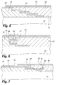
Fig. 5 is an enlarged sectional view corresponding toFig. 3 and shows a third embodiment of an overlap area between two lay-ups, -
Fig. 6 is an enlarged sectional view corresponding toFig. 2 and shows a fourth embodiment of an overlap area between two lay-ups, -
Fig. 7 is an enlarged sectional view corresponding toFig. 4 and shows in addition thereto a guide rod arranged in the overlap area between the two lay-ups, -
Fig. 8 shows schematically a transverse sectional view through mould parts to be used for manufacturing a wind turbine blade by hollow moulding and by means of the method according to the invention, -
Fig. 9 shows schematically a sectional view along the lines IX-IX inFig. 8 , -
Fig. 10 is a schematic, longitudinal, sectional view through a joint area between shell sections being manufactured by means of the method according to the invention and shows a first example of a guide means assisting in guiding the shell sections into their assembled position, -
Fig. 11 is a view corresponding toFig. 10 showing, however, a second example of a guide means, -
Fig. 12 is a sectional view corresponding toFig. 10 showing, however, a first example of connection means for mechanically connecting two shell sections manufactured by means of the method according to the invention, and -
Fig. 13 is a sectional view corresponding toFig. 12 showing, however, a second example of a mechanical connection means. -
Fig. 1 is a schematic view of awind turbine blade 1 having the shape of a conventional blade of an up-wind wind turbine according to the so-called "Danish concept". Theblade 1 has a longitudinal axis L and comprises aroot region 2, a profile orairfoil region 3, and atransition region 4 between theroot region 2 and theairfoil region 3. Theblade 1 comprises aleading edge 5 and a trailingedge 6. Achordal plane 7 extends between theleading edge 5 and the trailing 6 and defines the transition between asuction side 8 and a pressure side 9 of theblade 1. The chordal plane is illustrated by means of a dot-and-dash line. As previously mentioned, theblade 1 is manufactured by using two separately manufactured shell halves, i.e. a pressure side shell half and a suction side shell half of the blade, and subsequently gluing the two shell halves together. Alternatively, the blade may be manufactured by a hollow moulding method as explained later. - The method according to the invention is now explained by means of an embodiment for producing the pressure side shell half by reference to
Figs. 2 and4 . - As indicated in
Fig. 1 , theshell half 10 comprises two separate shell half sections, i.e. a first and a secondshell half section Figs. 12 and 13 show a fraction of the manufactured shell halves 11,12 assembled to form theshell half 10. - A first
rigid mould part 13 is used for manufacturing theshell half 10. The firstrigid mould part 13 has a first formingsurface 14 with a contour defining the outer surface of theshell half 10, i.e. the pressure side 9. - A first fibre lay-
up 15 is arranged in a firstlongitudinal section 16 of thefirst mould part 13. The first fibre lay-up 15 has a firstcrosswise edge area 17. Thereafter, a firstflexible polymer foil 18 is arranged over the first fibre lay-up 15 so as to cover the lay-up completely and is sealed to theedge 19 of thefirst mould part 13 so as to form afirst mould cavity 24. - Then, a second fibre lay-
up 20 is arranged in a secondlongitudinal section 21 so that the second fibre lay-up 20 overlaps the first crosswiseedge area 17 of the first fibre lay-up 15 and thereby the first flexible foil in anoverlap area 22. Theoverlap area 22 forms an interface between the fibre lay-ups. - Subsequently, a second
flexible polymer foil 23 is arranged over the second lay-up 20 so as to cover the second lay-up completely and is sealed to theedge 19 of the first mould part so as to form asecond mould cavity 25. - The mould cavities 24,25 are now evacuated by being connected to a non-shown vacuum source, whereupon liquid polymer, such as polyester or epoxy, is supplied to the
mould cavities - After curing, the formed first and second
shell half sections rigid mould part 13 and connected, preferably by gluing, to corresponding shell half sections so as to form two blade sections, thus forming thesuction side 8 of the wind turbine blade. Alternatively, when being connected to the corresponding shell half sections forming thesuction side 8 of the blade, the formedshell half sections first mould part 13. Thereafter, the formed blade sections are removed from the mould part and separated from each other. Subsequently, the formed wind turbine sections may be transported to the site of use, where a wind power plant is to be erected, and then assembled. - Above, the method according to the invention has been illustrated by using VARTM for manufacturing a composite structure in the form of a wind turbine blade shell half. However, any method for producing fibre-reinforced composite structures may be used. As an example, it should be mentioned that by using pre-pregs, the method is carried out as illustrated above except that polymer is not supplied to the mould cavities after the evacuation thereof as pre-impregnated fibre material is used in the lay-ups. Instead, the mould part is heated after evacuation of the mould cavities in order to liquefy the polymer, which is cured thereafter.
- In the above embodiment, the overlap area, i.e. the
interface 22, between the fibre lay-ups upper surface 26 of the first lay-up 15 towards the first formingsurface 14 of thefirst mould part 13. As shown inFig. 5 , theinterface 22 between the lay-ups tongue 27 andglue 28, as shown inFig. 6 , or in its entirety extend essentially parallel to the longitudinal axis of the shell half, i.e. thefirst mould part 13, as shown inFig. 3 . In fact, theinterface 22 between the lay-ups - Further, in the above described embodiment, the overlap area, i.e. the
interface 22, between the first and second fibre lay-ups first mould part 13. However, as shown inFig. 2 by means of dotted lines, the overlap area may also extend obliquely to the longitudinal axis L. - As shown in
Fig. 7 , longitudinally extending guide means may be arranged in the first and the second fibre lay-ups overlap area 22 therebetween. The purpose of such guide means is to assist in fitting the formed shell half sections together, when they are to be assembled to form the shell half. InFig. 7 , the guide means is formed by aguide rod 29 arranged in the first and the second fibre lay-ups flexible foil 18 and so that afirst portion 30 of theguide rod 29 extends into the first fibre lay-up 15, and asecond portion 31 of theguide rod 29 extends into the second fibre lay-up 20. Thefirst end 30 of theguide rod 29 is provided with a release agent allowing the guide rod to be removed from the first shell half section formed by the first fibre lay-up 15 after curing of the polymer supplied to the first fibre lay-up. - As an alternative to arranging the guide means in the fibre lay-ups, guide means may be arranged on
upper surfaces shell half sections overlap area 22 therebetween and are preferably arranged while theshell half sections first mould part 13. Examples of such guide means are shown inFigs. 10 and11 . - In
Fig. 10 , the guide means 34 comprises aplate member 35 attached to theupper surface 32 of the firstshell half section 11 and extending past theoverlap area 22. The guide means 34 further comprises asecond member 36 attached to theupper surface 33 of the secondshell half section 12. Thesecond member 36 is shaped so as to form a receiving space 37 together with theupper surface 33 of the second shell section for fittingly receiving anend portion 38 of theplate member 35. - In
Fig. 11 , the guide means 39 comprises afirst block 40 attached to theupper surface 32 of the firstshell half section 11 and provided with a first through-goingbore 42, asecond block 41 attached to theupper surface 33 of the secondshell half section 12 and provided with a second through-goingbore 43, and a longitudinally extendingguide pin 44 received in the first and the second through-goingbores - When assembling the formed first and second
composite structure sections interface 22 between the sections. In addition to the glue joint, thecomposite structure sections Figs. 12 and 13 . - In
Fig. 12 , the interconnecting means 45 comprises a first plate provided with anopening second plate 49 provided with a hole with aninner thread plates screws respective holes shell half section 11 and the secondshell half section 12, respectively, and screwed into thethreads - The interconnecting means 56 shown in
Fig. 13 is based on the guide means shown inFig. 7 , which has here been provided with aninner thread hole 60 in the firstshell half section 11, afirst bolt 59 is screwed into theinner thread 57. Asecond bolt 61 is screwed through ahole 62 into aninner thread 58. - Although guide means and connection means have been described above by reference to shell
half sections - In order to illustrate how a hollow composite structure comprising two separate hollow composite structure sections can be manufactured in a closed mould by means of the invention, reference is made to
Figs. 8 and9 . The hollow composite structure is a wind turbine blade comprising two hollow blade sections. - The
mould 63 to be used in a VARTM process comprises a flexible andcollapsible mould core 64, the firstrigid mould part 13 described by reference toFigs. 2 and4 , and a secondrigid mould part 65 having a second formingsurface 66 with a contour defining an outer surface of the composite structure, in the present case an outer surface of the suction side of the blade. The first andsecond mould parts mould core 64 and to be sealed to each other along the edge thereof. The outer surface of the mould core may in itself be formed of a flexible and/or resilient polymer foil being able to function as a so-called vacuum foil or vacuum bag, or such a foil may be arranged over the entire outer surface of the mould core. - Initially, the first fibre lay-
up 15 is arranged on the firstlongitudinal section 16 of thefirst mould part 13 so as to define the first crosswiseedge area 17. Then, a firstflexible polymer foil 67 is arranged over the first crosswise edge area as shown inFig. 9 . - Then, the second fibre lay-
up 20 is arranged in the secondlongitudinal section 21 of thefirst mould part 13 so that it overlaps the first crosswise edge area of the first fibre lay-up and thereby the firstflexible foil 67 in the overlap area forming theinterface 22 between the fibre lay-ups - As shown more clearly in
Fig. 8 , the fibre lay-ups surface 14, one or more upper fibre layers 69 being separated from thelower fibre layer 68. Thelayers 68,69 are separated by means of afirst fibre insertion 70 comprising a plurality of fibre layers, afirst core part 71, and asecond core part 72 as well as a first fibre-reinforcement 73 comprising a plurality of fibre layers and a second fibre-reinforcement 74 comprising a plurality of fibre layers. - Next, the
mould core 64 is arranged on the first and second fibre lay-ups flexible foil 67. Thereafter, a third fibre lay-up 75 is arranged on a firstlongitudinal section 76 of themould core 64. The third fibre lay-up 75 has a second crosswiseedge area 77. Then, a thirdflexible foil 78 is arranged over the second crosswiseedge area 77. Thereafter, a fourth fibre lay-up 79 is arranged on a secondlongitudinal section 80 of themould core 64. The fourth fibre lay-up 79 is arranged so that it overlaps the second crosswiseedge area 77 of the third fibre lay-up 75 and thereby the thirdflexible foil 78 in anoverlap area 81 forming an interface between the third and the fourth fibre lay-ups. As is evident fromFig. 8 , the fibre lay-ups ups ups ups Fig. 8 , the overlap areas, i.e. interfaces, 22,81 merge into each other as seen circumferentially so as to form a circumferentially continuous overlap area between the lay-ups, i.e. the first and second hollow lay-ups. - The mould is now closed by arranging the
second mould part 65 over thefirst mould part 13 and themould core 64. Thereby, a firstcircumferential mould cavity 82 and a second circumferential mould cavity 83 are formed, said cavities being separated by means of the first and thirdflexible foil - Finally, the
circumferential mould cavities 82,83 are evacuated and liquid polymer supplied to the cavities, whereupon the polymer is allowed to cure. - When the polymer has cured, the formed hollow blade sections are removed from the mould and may be transported to the site of use, i.e. where a wind power plant is to be erected and assembled at that site.
- Finally, it should be noted that instead of arranging the third and fourth fibre lay-
ups third foil 78 on themould core 64, they could be arranged on the second formingsurface 66 of thesecond mould part 65 and retained in thesecond mould part 65, when it is arranged over the mould core and the first mould part in order to close the mould. - The invention has been described with reference to advantageous embodiments. However, the scope of the invention is not limited to the illustrated and described embodiments, and alterations and modifications can be carried out without deviating from the scope of the invention.
-
- 1.
- Wind turbine blade
- 2.
- Root region
- 3.
- Airfoil region
- 4.
- Transition region
- 5.
- Leading edge
- 6.
- Trailing edge
- 7.
- Chordal plane
- 8.
- Suction side
- 9.
- Pressure side
- L
- longitudinal axis
- 10.
- Composite structure; shell half
- 11.
- First composite structure section, first shell half section
- 12.
- Second composite structure section; second shell half section
- 13.
- First rigid mould part
- 14.
- First forming surface
- 15.
- First fibre lay-up
- 16.
- First longitudinal section
- 17.
- First crosswise edge area
- 18.
- First flexible polymer foil
- 19.
- Edge
- 20.
- Second fibre lay-up
- 21.
- Second longitudinal section
- 22.
- Overlap area; interface
- 23.
- Second flexible polymer foil
- 24.
- First mould cavity
- 25.
- Second mould cavity
- 26.
- Upper surface
- 27.
- Tongue
- 28.
- Groove
- 29.
- Guide rod
- 30.
- First portion
- 31.
- Second portion
- 32.
- First upper surface
- 33.
- Second upper surface
- 34.
- Guide means
- 35.
- Blade member
- 36.
- Second member
- 37.
- Receiving space
- 38.
- End portion
- 39.
- Guide means
- 40.
- First block
- 41.
- Second block
- 42.
- First through bore
- 43.
- Second through bore
- 44.
- Guide pin
- 45.
- Interconnecting means
- 46.
- First plate
- 47.
- Opening
- 48.
- Opening
- 49.
- Second plate
- 50.
- Hole with inner thread
- 51.
- Hole with inner thread
- 52.
- Screw
- 53.
- Screw
- 54.
- Hole
- 55.
- Hole
- 56.
- Interconnecting means
- 57.
- Inner thread
- 58.
- Inner thread
- 59.
- First bolt
- 60.
- Hole
- 61.
- Second bolt
- 62.
- Hole
- 63.
- Mould
- 64.
- Mould core
- 65.
- Second rigid mould part
- 66.
- Second forming surface
- 67.
- First polymer foil
- 68.
- Lower fibre layer
- 69.
- Upper fibre layer
- 70.
- First fibre insertion
- 71.
- First core part
- 72.
- Second core part
- 73.
- First fibre-reinforcement
- 74.
- Second fibre-reinforcement
- 75.
- Third fibre lay-up
- 76.
- First longitudinal section of mould core
- 77.
- Second crosswise edge area
- 78.
- Third flexible polymer foil
- 79.
- Fourth fibre lay-up
- 80.
- Second longitudinal section of mould core
- 81.
- Overlap area; interface
- 82.
- First circumferential mould cavity
- 83.
- Second circumferential mould cavity.
Claims (15)
- A method of manufacturing an elongated composite structure having a longitudinal axis and comprising at leasst a first and a second separate longitudinal composite structure section and being formed of reinforced polymer material including a polymer matrix and fibre material embedded in the polymer matrix, wherein the method comprises the followings steps:a) providing a first rigid mould part having a first forming surface with a contour defining an outer surface of the elongated composite structure,b) arranging a first fibre lay-up in a first longitudinal section of the first mould part, the first fibre lay-up defining a first crosswise edge area,c) arranging at least one first flexible and preferably resilient foil, preferably a polymer foil, over at least the first crosswise edge area of the first fibre lay-up,d) arranging a second fibre lay-up in a second longitudinal section of the first mould part so that the second fibre lay-up overlaps the first crosswise edge area of the first lay-up and thereby the first flexible foil in an overlap area forming an interface between the first fibre lay-up and second fibre lay-up,e) providing polymer to the first and second longitudinal sections simultaneously with steps a) and d), respectively, and/or after step d), andf) curing or allowing the polymer to cure.
- Method according to claim 1, wherein in step c) the at least one first flexible foil is arranged so as to cover the entire first fibre lay-up and is sealed to the first mould part to form a first mould cavity and wherein subsequent to step d) and prior to step f) a second flexible and preferably resilient foil, preferably a polymer foil, is arranged over the second fibre lay-up and sealed to the first mould part so as to form a second mould cavity.
- Method according to claim 1, further comprising the step of arranging at least one second flexible foil, preferably a polymer foil, over the first and the second lay-up and sealing the at least one second flexible foil to the first mould part to form a first mould cavity and a second mould cavity, the first and the second mould cavity being separated by the first flexible foil.
- Method according to claim 1, wherein the composite structure is a hollow structure formed in a closed mould, the closed mould comprising a flexible, preferably resilient, and collapsible mould core, the first rigid mould part and a second rigid mould part having a second forming surface with a contour defining an outer surface of the composite structure, the first and second mould part being arranged to close around the mould core, and wherein subsequent to step d):- the mould core is arranged on the first and second fibre lay-up and the first flexible foil,- a third fibre lay-up is arranged on a first longitudinal section of the core and/or the second mould part, the third fibre lay-up defining a second crosswise edge area,- a third flexible foil, preferably a polymer foil, is arranged over at least the second crosswise edge area,- a fourth fibre lay-up is arranged on a second longitudinal section of the core and/or the second mould part so that the fourth fibre lay-up overlaps the second crosswise edge area of the third fibre lay-up and thereby the third flexible foil in a second overlap area forming a second interface between the third and the fourth lay-up, and- the mould is closed by arranging the second mould part over the first mould part and the mould core to form a first circumferential mould cavity and a second circumferential mould cavity, the first and the second circumferential mould cavities being separated by means of the first and third flexible foil.
- Method according to any of the claims 2-4, wherein the first and the second mould cavities are evacuated prior to step e).
- Method according to any of the claims 2-5, wherein fluid polymer is supplied to the first and the second mould cavity during step e) to fill the mould cavities with polymer.
- Method according to any of the preceding claims, wherein pre-impregnated fibre material is arranged in the first and/or the second longitudinal section of the first mould part during step b) and/or step d).
- Method according to any of the preceding claims, wherein the interface between the first and the second fibre lay-ups and/or the third and fourth lay-ups, respectively, is substantially parallel to the longitudinal axis of the composite structure to be manufactured.
- Method according to any of the preceding claims 1-7, wherein the interface between the first and the second fibre lay-ups is tapering from an upper surface of the first fibre lay-up towards the first forming surface of the first mould part.
- Method according to claim 9, wherein the interface tapers gradually.
- Method according to any of the preceding claims, wherein the interface between the first and the second fibre lay-ups and/or the third and fourth lay-ups, respectively, is formed as a tongue and a groove in the respective lay-ups.
- Method according to any of the claims 1-3 and 5-11, wherein the composite structure is at least a part of a shell half of a wind turbine blade, the first and the second composite structure sections forming respective longitudinal sections of the shell half of the wind turbine blade.
- Method according to claim 4, wherein the hollow composite structure is at least a part of a wind turbine blade, the first and the second hollow composite structure sections forming respective longitudinal sections of the wind turbine blade.
- Method according to any of the proceeding claims, wherein after curing of the polymer the formed composite structure is removed from the mould and the first composite structure section is separated from the second composite structure section.
- Method according to claim 14 further comprising transportation of the first and second composite structure sections to the site of use and interconnection of the first and second composite structure sections at the site.
Priority Applications (9)
| Application Number | Priority Date | Filing Date | Title |
|---|---|---|---|
| EP10172792.3A EP2418072B1 (en) | 2010-08-13 | 2010-08-13 | A method of manufacturing an elongated composite structure |
| TR2018/10926T TR201810926T4 (en) | 2010-08-13 | 2010-08-13 | A method for manufacturing an elongated composite structure. |
| ES10172792.3T ES2692442T3 (en) | 2010-08-13 | 2010-08-13 | Method of manufacturing an elongated composite structure |
| PL10172792T PL2418072T3 (en) | 2010-08-13 | 2010-08-13 | A method of manufacturing an elongated composite structure |
| DK10172792.3T DK2418072T3 (en) | 2010-08-13 | 2010-08-13 | A method of making an elongate composite body |
| US13/813,581 US9050786B2 (en) | 2010-08-13 | 2011-07-20 | Method of manufacturing an elongated composite structure |
| CN201180049396.3A CN103153592B (en) | 2010-08-13 | 2011-07-20 | Method of making elongated composite structures |
| IN729CHN2013 IN2013CN00729A (en) | 2010-08-13 | 2011-07-20 | |
| PCT/EP2011/062474 WO2012019888A1 (en) | 2010-08-13 | 2011-07-20 | A method of manufacturing an elongated composite structure |
Applications Claiming Priority (1)
| Application Number | Priority Date | Filing Date | Title |
|---|---|---|---|
| EP10172792.3A EP2418072B1 (en) | 2010-08-13 | 2010-08-13 | A method of manufacturing an elongated composite structure |
Publications (2)
| Publication Number | Publication Date |
|---|---|
| EP2418072A1 true EP2418072A1 (en) | 2012-02-15 |
| EP2418072B1 EP2418072B1 (en) | 2018-07-25 |
Family
ID=43432247
Family Applications (1)
| Application Number | Title | Priority Date | Filing Date |
|---|---|---|---|
| EP10172792.3A Active EP2418072B1 (en) | 2010-08-13 | 2010-08-13 | A method of manufacturing an elongated composite structure |
Country Status (9)
| Country | Link |
|---|---|
| US (1) | US9050786B2 (en) |
| EP (1) | EP2418072B1 (en) |
| CN (1) | CN103153592B (en) |
| DK (1) | DK2418072T3 (en) |
| ES (1) | ES2692442T3 (en) |
| IN (1) | IN2013CN00729A (en) |
| PL (1) | PL2418072T3 (en) |
| TR (1) | TR201810926T4 (en) |
| WO (1) | WO2012019888A1 (en) |
Cited By (5)
| Publication number | Priority date | Publication date | Assignee | Title |
|---|---|---|---|---|
| WO2018215457A1 (en) | 2017-05-22 | 2018-11-29 | Lm Wind Power International Technology Ii Aps | Wind turbine blade and method of assembly of blade elements to form a wind turbine blade |
| WO2020089069A1 (en) * | 2018-10-29 | 2020-05-07 | Blade Dynamics Limited | Sealing member for a sectioned wind turbine blade |
| CN111791405A (en) * | 2020-07-24 | 2020-10-20 | 中国航空工业集团公司济南特种结构研究所 | Combined die split body linear separation structure and method for composite material forming |
| CN114655450A (en) * | 2022-03-10 | 2022-06-24 | 中国航发沈阳发动机研究所 | A perforated sound-absorbing board layup structure, prepreg and prepreg layup method |
| EP4050202A1 (en) | 2021-02-24 | 2022-08-31 | LM Wind Power A/S | A method of assembling a wind turbine blade |
Families Citing this family (14)
| Publication number | Priority date | Publication date | Assignee | Title |
|---|---|---|---|---|
| DE102009046293B4 (en) * | 2009-11-02 | 2013-03-28 | Repower Systems Ag | Rotor blade with drainage hole |
| ES2853374T3 (en) * | 2014-01-31 | 2021-09-15 | Lm Wp Patent Holding As | Method for manufacturing a wind turbine blade part in two steps |
| EP2918404A1 (en) * | 2014-03-10 | 2015-09-16 | Siemens Aktiengesellschaft | A method and a mold for manufacturing a component for a wind turbine |
| US9926949B2 (en) | 2014-04-15 | 2018-03-27 | Tk Holdings Inc. | Silicone propelled pedestrian hood lifter and seatbelt pre-tensioner |
| US9517606B2 (en) * | 2014-08-06 | 2016-12-13 | The Boeing Company | Composite structure and method of forming thereof |
| CN106915100A (en) * | 2015-12-28 | 2017-07-04 | 明安国际企业股份有限公司 | Flat workpiece support device and manufacturing method thereof |
| GB201619713D0 (en) * | 2016-11-22 | 2017-01-04 | Swedish Biomimetics 3000 Ltd | Elongate solid phase body |
| US11396154B2 (en) * | 2017-12-21 | 2022-07-26 | Vestas Wind Systems A/S | Modular wind turbine blade and associated method of manufacture |
| US11845236B2 (en) * | 2018-03-12 | 2023-12-19 | The Boeing Company | Composite structure splice and method |
| ES2757536B2 (en) | 2018-10-29 | 2020-12-01 | Siemens Gamesa Renewable Energy Innovation & Technology SL | Manufacturing method of a panel of a wind turbine nacelle |
| ES2963699T3 (en) | 2018-12-10 | 2024-04-01 | Vestas Wind Sys As | Method for manufacturing a flange section of a wind turbine blade shear web and a wind turbine blade shear web |
| US11131290B2 (en) * | 2019-06-25 | 2021-09-28 | General Electric Company | Scarf connection for a wind turbine rotor blade |
| US12221951B2 (en) | 2019-09-13 | 2025-02-11 | Siemens Gamesa Renewable Energy Innovation & Technology S.L. | Wind turbine blade |
| CN112659581A (en) * | 2021-01-15 | 2021-04-16 | 洛阳双瑞风电叶片有限公司 | Fixing assembly for embedded blade and manufacturing method of embedded blade |
Citations (5)
| Publication number | Priority date | Publication date | Assignee | Title |
|---|---|---|---|---|
| US3967996A (en) * | 1973-05-14 | 1976-07-06 | Nikolai Ilich Kamov | Method of manufacture of hollow pieces |
| EP1310351A1 (en) | 2001-11-13 | 2003-05-14 | Bonus Energy A/S | Method for manufacturing windmill blades |
| EP1584817A1 (en) | 2004-04-07 | 2005-10-12 | Gamesa Eolica, S.A. (Sociedad Unipersonal) | Wind turbine blade |
| WO2006002621A1 (en) * | 2004-06-30 | 2006-01-12 | Vestas Wind Systems A/S | Wind turbine blades made of two separate sections, and method of assembly |
| US20080115887A1 (en) * | 2006-11-22 | 2008-05-22 | Airbus Uk Limited | Method for forming a feature in a piece of composite material |
Family Cites Families (4)
| Publication number | Priority date | Publication date | Assignee | Title |
|---|---|---|---|---|
| US2276035A (en) * | 1940-07-24 | 1942-03-10 | Westinghouse Electric & Mfg Co | Method of molding laminated articles |
| FR2879498B1 (en) * | 2004-12-16 | 2009-01-30 | Snecma Propulsion Solide Sa | DENSIFICATION OF FIBROUS STRUCTURES BY RTM FOR THE PRODUCTION OF PARTS IN COMPOSITE MATERIAL |
| DK2106900T3 (en) * | 2008-04-03 | 2012-07-09 | Siemens Ag | Form and Method of Vacuum Supported Resino Transfer Molding |
| US20110254189A1 (en) * | 2008-10-10 | 2011-10-20 | Eirecomposites Teoranta | Heated mould for moulding polymeric composites |
-
2010
- 2010-08-13 DK DK10172792.3T patent/DK2418072T3/en active
- 2010-08-13 ES ES10172792.3T patent/ES2692442T3/en active Active
- 2010-08-13 TR TR2018/10926T patent/TR201810926T4/en unknown
- 2010-08-13 PL PL10172792T patent/PL2418072T3/en unknown
- 2010-08-13 EP EP10172792.3A patent/EP2418072B1/en active Active
-
2011
- 2011-07-20 US US13/813,581 patent/US9050786B2/en active Active
- 2011-07-20 CN CN201180049396.3A patent/CN103153592B/en active Active
- 2011-07-20 WO PCT/EP2011/062474 patent/WO2012019888A1/en not_active Ceased
- 2011-07-20 IN IN729CHN2013 patent/IN2013CN00729A/en unknown
Patent Citations (5)
| Publication number | Priority date | Publication date | Assignee | Title |
|---|---|---|---|---|
| US3967996A (en) * | 1973-05-14 | 1976-07-06 | Nikolai Ilich Kamov | Method of manufacture of hollow pieces |
| EP1310351A1 (en) | 2001-11-13 | 2003-05-14 | Bonus Energy A/S | Method for manufacturing windmill blades |
| EP1584817A1 (en) | 2004-04-07 | 2005-10-12 | Gamesa Eolica, S.A. (Sociedad Unipersonal) | Wind turbine blade |
| WO2006002621A1 (en) * | 2004-06-30 | 2006-01-12 | Vestas Wind Systems A/S | Wind turbine blades made of two separate sections, and method of assembly |
| US20080115887A1 (en) * | 2006-11-22 | 2008-05-22 | Airbus Uk Limited | Method for forming a feature in a piece of composite material |
Cited By (8)
| Publication number | Priority date | Publication date | Assignee | Title |
|---|---|---|---|---|
| WO2018215457A1 (en) | 2017-05-22 | 2018-11-29 | Lm Wind Power International Technology Ii Aps | Wind turbine blade and method of assembly of blade elements to form a wind turbine blade |
| US11286908B2 (en) | 2017-05-22 | 2022-03-29 | Lm Wind Power Us Technology Aps | Wind turbine blade and method of assembly of blade elements to form a wind turbine blade |
| WO2020089069A1 (en) * | 2018-10-29 | 2020-05-07 | Blade Dynamics Limited | Sealing member for a sectioned wind turbine blade |
| US11486351B2 (en) | 2018-10-29 | 2022-11-01 | Blade Dynamics Limited | Sealing member for a sectioned wind turbine blade |
| CN111791405A (en) * | 2020-07-24 | 2020-10-20 | 中国航空工业集团公司济南特种结构研究所 | Combined die split body linear separation structure and method for composite material forming |
| CN111791405B (en) * | 2020-07-24 | 2022-04-19 | 中国航空工业集团公司济南特种结构研究所 | Combined die split body linear separation structure and method for composite material forming |
| EP4050202A1 (en) | 2021-02-24 | 2022-08-31 | LM Wind Power A/S | A method of assembling a wind turbine blade |
| CN114655450A (en) * | 2022-03-10 | 2022-06-24 | 中国航发沈阳发动机研究所 | A perforated sound-absorbing board layup structure, prepreg and prepreg layup method |
Also Published As
| Publication number | Publication date |
|---|---|
| WO2012019888A1 (en) | 2012-02-16 |
| CN103153592B (en) | 2015-06-17 |
| US20130126089A1 (en) | 2013-05-23 |
| IN2013CN00729A (en) | 2015-07-03 |
| TR201810926T4 (en) | 2018-08-27 |
| US9050786B2 (en) | 2015-06-09 |
| EP2418072B1 (en) | 2018-07-25 |
| ES2692442T3 (en) | 2018-12-03 |
| PL2418072T3 (en) | 2018-12-31 |
| CN103153592A (en) | 2013-06-12 |
| DK2418072T3 (en) | 2018-11-19 |
Similar Documents
| Publication | Publication Date | Title |
|---|---|---|
| EP2418072B1 (en) | A method of manufacturing an elongated composite structure | |
| US9599094B2 (en) | Method of manufacturing an aerodynamic shell part for a wind turbine blade | |
| EP3019316B1 (en) | Method and tools for manufacturing a wind turbine blade | |
| US9221219B2 (en) | Method of producing a composite structure via intermediate products, the related apparatus and a composite structure obtainable by the method | |
| EP3099477B1 (en) | Wind turbine blade with improved fibre transition | |
| EP3099471B1 (en) | Method for manufacturing a wind turbine blade part in two steps | |
| EP3112668A1 (en) | Blade root section for a modular rotor blade and method of manufacturing same | |
| EP3548261B1 (en) | Method and system for manufacturing a shear web for a wind turbine blade | |
| US12203442B2 (en) | Method and system of manufacturing a wind turbine blade | |
| CN113382849A (en) | Method for manufacturing a fibre-reinforced polymer composite beam, in particular an airfoil beam for a wind turbine rotor blade | |
| US11542917B2 (en) | Beam structure for a segmented rotor blade having a transitioning shape |
Legal Events
| Date | Code | Title | Description |
|---|---|---|---|
| AK | Designated contracting states |
Kind code of ref document: A1 Designated state(s): AL AT BE BG CH CY CZ DE DK EE ES FI FR GB GR HR HU IE IS IT LI LT LU LV MC MK MT NL NO PL PT RO SE SI SK SM TR |
|
| AX | Request for extension of the european patent |
Extension state: BA ME RS |
|
| PUAI | Public reference made under article 153(3) epc to a published international application that has entered the european phase |
Free format text: ORIGINAL CODE: 0009012 |
|
| 17P | Request for examination filed |
Effective date: 20120808 |
|
| RAP1 | Party data changed (applicant data changed or rights of an application transferred) |
Owner name: LM WIND POWER A/S |
|
| 17Q | First examination report despatched |
Effective date: 20160517 |
|
| REG | Reference to a national code |
Ref country code: DE Ref legal event code: R079 Ref document number: 602010052121 Country of ref document: DE Free format text: PREVIOUS MAIN CLASS: B29C0070480000 Ipc: B32B0037140000 |
|
| GRAP | Despatch of communication of intention to grant a patent |
Free format text: ORIGINAL CODE: EPIDOSNIGR1 |
|
| STAA | Information on the status of an ep patent application or granted ep patent |
Free format text: STATUS: GRANT OF PATENT IS INTENDED |
|
| RIC1 | Information provided on ipc code assigned before grant |
Ipc: B29K 101/10 20060101ALI20180129BHEP Ipc: B29L 31/08 20060101ALI20180129BHEP Ipc: B32B 37/14 20060101AFI20180129BHEP Ipc: B29D 99/00 20100101ALI20180129BHEP Ipc: B29C 70/48 20060101ALI20180129BHEP |
|
| INTG | Intention to grant announced |
Effective date: 20180215 |
|
| GRAS | Grant fee paid |
Free format text: ORIGINAL CODE: EPIDOSNIGR3 |
|
| GRAA | (expected) grant |
Free format text: ORIGINAL CODE: 0009210 |
|
| STAA | Information on the status of an ep patent application or granted ep patent |
Free format text: STATUS: THE PATENT HAS BEEN GRANTED |
|
| RAP1 | Party data changed (applicant data changed or rights of an application transferred) |
Owner name: LM WP PATENT HOLDING A/S |
|
| AK | Designated contracting states |
Kind code of ref document: B1 Designated state(s): AL AT BE BG CH CY CZ DE DK EE ES FI FR GB GR HR HU IE IS IT LI LT LU LV MC MK MT NL NO PL PT RO SE SI SK SM TR |
|
| REG | Reference to a national code |
Ref country code: GB Ref legal event code: FG4D |
|
| REG | Reference to a national code |
Ref country code: CH Ref legal event code: EP |
|
| RAP2 | Party data changed (patent owner data changed or rights of a patent transferred) |
Owner name: LM WIND POWER INTERNATIONAL TECHNOLOGY II APS |
|
| REG | Reference to a national code |
Ref country code: AT Ref legal event code: REF Ref document number: 1021315 Country of ref document: AT Kind code of ref document: T Effective date: 20180815 |
|
| REG | Reference to a national code |
Ref country code: IE Ref legal event code: FG4D Ref country code: FR Ref legal event code: PLFP Year of fee payment: 9 |
|
| REG | Reference to a national code |
Ref country code: DE Ref legal event code: R096 Ref document number: 602010052121 Country of ref document: DE |
|
| REG | Reference to a national code |
Ref country code: DK Ref legal event code: T3 Effective date: 20181112 |
|
| REG | Reference to a national code |
Ref country code: NL Ref legal event code: MP Effective date: 20180725 |
|
| REG | Reference to a national code |
Ref country code: ES Ref legal event code: FG2A Ref document number: 2692442 Country of ref document: ES Kind code of ref document: T3 Effective date: 20181203 |
|
| REG | Reference to a national code |
Ref country code: LT Ref legal event code: MG4D |
|
| PG25 | Lapsed in a contracting state [announced via postgrant information from national office to epo] |
Ref country code: NL Free format text: LAPSE BECAUSE OF FAILURE TO SUBMIT A TRANSLATION OF THE DESCRIPTION OR TO PAY THE FEE WITHIN THE PRESCRIBED TIME-LIMIT Effective date: 20180725 |
|
| REG | Reference to a national code |
Ref country code: AT Ref legal event code: MK05 Ref document number: 1021315 Country of ref document: AT Kind code of ref document: T Effective date: 20180725 |
|
| PG25 | Lapsed in a contracting state [announced via postgrant information from national office to epo] |
Ref country code: GR Free format text: LAPSE BECAUSE OF FAILURE TO SUBMIT A TRANSLATION OF THE DESCRIPTION OR TO PAY THE FEE WITHIN THE PRESCRIBED TIME-LIMIT Effective date: 20181026 Ref country code: NO Free format text: LAPSE BECAUSE OF FAILURE TO SUBMIT A TRANSLATION OF THE DESCRIPTION OR TO PAY THE FEE WITHIN THE PRESCRIBED TIME-LIMIT Effective date: 20181025 Ref country code: SE Free format text: LAPSE BECAUSE OF FAILURE TO SUBMIT A TRANSLATION OF THE DESCRIPTION OR TO PAY THE FEE WITHIN THE PRESCRIBED TIME-LIMIT Effective date: 20180725 Ref country code: FI Free format text: LAPSE BECAUSE OF FAILURE TO SUBMIT A TRANSLATION OF THE DESCRIPTION OR TO PAY THE FEE WITHIN THE PRESCRIBED TIME-LIMIT Effective date: 20180725 Ref country code: LT Free format text: LAPSE BECAUSE OF FAILURE TO SUBMIT A TRANSLATION OF THE DESCRIPTION OR TO PAY THE FEE WITHIN THE PRESCRIBED TIME-LIMIT Effective date: 20180725 Ref country code: AT Free format text: LAPSE BECAUSE OF FAILURE TO SUBMIT A TRANSLATION OF THE DESCRIPTION OR TO PAY THE FEE WITHIN THE PRESCRIBED TIME-LIMIT Effective date: 20180725 Ref country code: IS Free format text: LAPSE BECAUSE OF FAILURE TO SUBMIT A TRANSLATION OF THE DESCRIPTION OR TO PAY THE FEE WITHIN THE PRESCRIBED TIME-LIMIT Effective date: 20181125 Ref country code: BG Free format text: LAPSE BECAUSE OF FAILURE TO SUBMIT A TRANSLATION OF THE DESCRIPTION OR TO PAY THE FEE WITHIN THE PRESCRIBED TIME-LIMIT Effective date: 20181025 |
|
| PG25 | Lapsed in a contracting state [announced via postgrant information from national office to epo] |
Ref country code: AL Free format text: LAPSE BECAUSE OF FAILURE TO SUBMIT A TRANSLATION OF THE DESCRIPTION OR TO PAY THE FEE WITHIN THE PRESCRIBED TIME-LIMIT Effective date: 20180725 Ref country code: LV Free format text: LAPSE BECAUSE OF FAILURE TO SUBMIT A TRANSLATION OF THE DESCRIPTION OR TO PAY THE FEE WITHIN THE PRESCRIBED TIME-LIMIT Effective date: 20180725 Ref country code: HR Free format text: LAPSE BECAUSE OF FAILURE TO SUBMIT A TRANSLATION OF THE DESCRIPTION OR TO PAY THE FEE WITHIN THE PRESCRIBED TIME-LIMIT Effective date: 20180725 |
|
| REG | Reference to a national code |
Ref country code: CH Ref legal event code: PL |
|
| REG | Reference to a national code |
Ref country code: DE Ref legal event code: R097 Ref document number: 602010052121 Country of ref document: DE |
|
| PG25 | Lapsed in a contracting state [announced via postgrant information from national office to epo] |
Ref country code: EE Free format text: LAPSE BECAUSE OF FAILURE TO SUBMIT A TRANSLATION OF THE DESCRIPTION OR TO PAY THE FEE WITHIN THE PRESCRIBED TIME-LIMIT Effective date: 20180725 Ref country code: MC Free format text: LAPSE BECAUSE OF FAILURE TO SUBMIT A TRANSLATION OF THE DESCRIPTION OR TO PAY THE FEE WITHIN THE PRESCRIBED TIME-LIMIT Effective date: 20180725 Ref country code: LI Free format text: LAPSE BECAUSE OF NON-PAYMENT OF DUE FEES Effective date: 20180831 Ref country code: IT Free format text: LAPSE BECAUSE OF FAILURE TO SUBMIT A TRANSLATION OF THE DESCRIPTION OR TO PAY THE FEE WITHIN THE PRESCRIBED TIME-LIMIT Effective date: 20180725 Ref country code: RO Free format text: LAPSE BECAUSE OF FAILURE TO SUBMIT A TRANSLATION OF THE DESCRIPTION OR TO PAY THE FEE WITHIN THE PRESCRIBED TIME-LIMIT Effective date: 20180725 Ref country code: CZ Free format text: LAPSE BECAUSE OF FAILURE TO SUBMIT A TRANSLATION OF THE DESCRIPTION OR TO PAY THE FEE WITHIN THE PRESCRIBED TIME-LIMIT Effective date: 20180725 Ref country code: CH Free format text: LAPSE BECAUSE OF NON-PAYMENT OF DUE FEES Effective date: 20180831 Ref country code: LU Free format text: LAPSE BECAUSE OF NON-PAYMENT OF DUE FEES Effective date: 20180813 |
|
| REG | Reference to a national code |
Ref country code: BE Ref legal event code: MM Effective date: 20180831 |
|
| PG25 | Lapsed in a contracting state [announced via postgrant information from national office to epo] |
Ref country code: SM Free format text: LAPSE BECAUSE OF FAILURE TO SUBMIT A TRANSLATION OF THE DESCRIPTION OR TO PAY THE FEE WITHIN THE PRESCRIBED TIME-LIMIT Effective date: 20180725 Ref country code: SK Free format text: LAPSE BECAUSE OF FAILURE TO SUBMIT A TRANSLATION OF THE DESCRIPTION OR TO PAY THE FEE WITHIN THE PRESCRIBED TIME-LIMIT Effective date: 20180725 |
|
| PLBE | No opposition filed within time limit |
Free format text: ORIGINAL CODE: 0009261 |
|
| STAA | Information on the status of an ep patent application or granted ep patent |
Free format text: STATUS: NO OPPOSITION FILED WITHIN TIME LIMIT |
|
| 26N | No opposition filed |
Effective date: 20190426 |
|
| PG25 | Lapsed in a contracting state [announced via postgrant information from national office to epo] |
Ref country code: SI Free format text: LAPSE BECAUSE OF FAILURE TO SUBMIT A TRANSLATION OF THE DESCRIPTION OR TO PAY THE FEE WITHIN THE PRESCRIBED TIME-LIMIT Effective date: 20180725 Ref country code: BE Free format text: LAPSE BECAUSE OF NON-PAYMENT OF DUE FEES Effective date: 20180831 |
|
| PG25 | Lapsed in a contracting state [announced via postgrant information from national office to epo] |
Ref country code: MT Free format text: LAPSE BECAUSE OF NON-PAYMENT OF DUE FEES Effective date: 20180813 |
|
| PG25 | Lapsed in a contracting state [announced via postgrant information from national office to epo] |
Ref country code: PT Free format text: LAPSE BECAUSE OF FAILURE TO SUBMIT A TRANSLATION OF THE DESCRIPTION OR TO PAY THE FEE WITHIN THE PRESCRIBED TIME-LIMIT Effective date: 20180725 Ref country code: HU Free format text: LAPSE BECAUSE OF FAILURE TO SUBMIT A TRANSLATION OF THE DESCRIPTION OR TO PAY THE FEE WITHIN THE PRESCRIBED TIME-LIMIT; INVALID AB INITIO Effective date: 20100813 |
|
| PG25 | Lapsed in a contracting state [announced via postgrant information from national office to epo] |
Ref country code: CY Free format text: LAPSE BECAUSE OF FAILURE TO SUBMIT A TRANSLATION OF THE DESCRIPTION OR TO PAY THE FEE WITHIN THE PRESCRIBED TIME-LIMIT Effective date: 20180725 Ref country code: MK Free format text: LAPSE BECAUSE OF NON-PAYMENT OF DUE FEES Effective date: 20180725 |
|
| P01 | Opt-out of the competence of the unified patent court (upc) registered |
Effective date: 20230522 |
|
| PGFP | Annual fee paid to national office [announced via postgrant information from national office to epo] |
Ref country code: IE Payment date: 20240725 Year of fee payment: 15 |
|
| PGFP | Annual fee paid to national office [announced via postgrant information from national office to epo] |
Ref country code: ES Payment date: 20250901 Year of fee payment: 16 |
|
| PGFP | Annual fee paid to national office [announced via postgrant information from national office to epo] |
Ref country code: DK Payment date: 20250723 Year of fee payment: 16 Ref country code: DE Payment date: 20250724 Year of fee payment: 16 |
|
| PGFP | Annual fee paid to national office [announced via postgrant information from national office to epo] |
Ref country code: PL Payment date: 20250724 Year of fee payment: 16 Ref country code: TR Payment date: 20250728 Year of fee payment: 16 |
|
| PGFP | Annual fee paid to national office [announced via postgrant information from national office to epo] |
Ref country code: GB Payment date: 20250725 Year of fee payment: 16 |
|
| PGFP | Annual fee paid to national office [announced via postgrant information from national office to epo] |
Ref country code: FR Payment date: 20250723 Year of fee payment: 16 |