EP2418006B1 - Arrangement for a roller ski and a roller ski - Google Patents
Arrangement for a roller ski and a roller ski Download PDFInfo
- Publication number
- EP2418006B1 EP2418006B1 EP20100171857 EP10171857A EP2418006B1 EP 2418006 B1 EP2418006 B1 EP 2418006B1 EP 20100171857 EP20100171857 EP 20100171857 EP 10171857 A EP10171857 A EP 10171857A EP 2418006 B1 EP2418006 B1 EP 2418006B1
- Authority
- EP
- European Patent Office
- Prior art keywords
- arrangement
- roller
- roller ski
- brake means
- ski
- Prior art date
- Legal status (The legal status is an assumption and is not a legal conclusion. Google has not performed a legal analysis and makes no representation as to the accuracy of the status listed.)
- Not-in-force
Links
- 230000000694 effects Effects 0.000 claims description 20
- 230000036316 preload Effects 0.000 claims description 7
- 238000010276 construction Methods 0.000 description 9
- 238000005096 rolling process Methods 0.000 description 7
- 229910052751 metal Inorganic materials 0.000 description 5
- 239000002184 metal Substances 0.000 description 5
- 238000000034 method Methods 0.000 description 3
- 238000013459 approach Methods 0.000 description 2
- 238000012423 maintenance Methods 0.000 description 2
- 239000000463 material Substances 0.000 description 2
- 230000007246 mechanism Effects 0.000 description 2
- 239000004033 plastic Substances 0.000 description 2
- 229920003023 plastic Polymers 0.000 description 2
- 239000005060 rubber Substances 0.000 description 2
- XLYOFNOQVPJJNP-UHFFFAOYSA-N water Substances O XLYOFNOQVPJJNP-UHFFFAOYSA-N 0.000 description 2
- 229910000851 Alloy steel Inorganic materials 0.000 description 1
- 229910000831 Steel Inorganic materials 0.000 description 1
- 229910045601 alloy Inorganic materials 0.000 description 1
- 239000000956 alloy Substances 0.000 description 1
- 239000004411 aluminium Substances 0.000 description 1
- 229910052782 aluminium Inorganic materials 0.000 description 1
- XAGFODPZIPBFFR-UHFFFAOYSA-N aluminium Chemical compound [Al] XAGFODPZIPBFFR-UHFFFAOYSA-N 0.000 description 1
- 239000002131 composite material Substances 0.000 description 1
- 238000007689 inspection Methods 0.000 description 1
- 239000010959 steel Substances 0.000 description 1
Images




Classifications
-
- A—HUMAN NECESSITIES
- A63—SPORTS; GAMES; AMUSEMENTS
- A63C—SKATES; SKIS; ROLLER SKATES; DESIGN OR LAYOUT OF COURTS, RINKS OR THE LIKE
- A63C17/00—Roller skates; Skate-boards
- A63C17/04—Roller skates; Skate-boards with wheels arranged otherwise than in two pairs
- A63C17/045—Roller skis
-
- A—HUMAN NECESSITIES
- A63—SPORTS; GAMES; AMUSEMENTS
- A63C—SKATES; SKIS; ROLLER SKATES; DESIGN OR LAYOUT OF COURTS, RINKS OR THE LIKE
- A63C17/00—Roller skates; Skate-boards
- A63C17/14—Roller skates; Skate-boards with brakes, e.g. toe stoppers, freewheel roller clutches
- A63C17/1409—Roller skates; Skate-boards with brakes, e.g. toe stoppers, freewheel roller clutches contacting one or more of the wheels
Definitions
- the present invention relates to roller skis suitable for skiing in the classic style, i.e. where a diagonal stride is used.
- Roller skis are most commonly used as an efficient training method for cross-country skiers who do not have the possibility to always train on snow, for example during summer.
- roller skis are provided with front and rear wheels where either wheel is provided with a ratchet mechanism such that a user will have sufficient grip during the kick-phase of a diagonal stride.
- a problem with that type of ratchet mechanisms is that they provide full grip even if a skier does not perform a faultless stride. This form a contrast to cross-country skiing on snow where a correctly performed diagonal stride is essential to obtain sufficient grip and avoid that the ski slip backwards. Using roller skis of that type may therefore cause a skier to adapt an incorrect technique.
- US-2008/0030014 discloses a prior art roller ski which aims to overcome this problem. That prior art discloses several different approaches to solve the problem, among other a solution where a wheel mount is pivotally connected to the rest of the roller ski. The wheel mount is biased by a spring mounted within the roller ski. The manner in which the spring is mounted provides only limited possibilities to adjust the bias to match with different skiers having different techniques and physique.
- an arrangement for a roller ski comprising a first roller wheel and a fixing element for attaching the arrangement to an elongated body of a roller ski.
- the fixing element has an upper side and a lower side.
- the arrangement further comprises a pivoting element connected to the fixing element by means of a pivotal connection, which pivotal connection has a rotational axis that is perpendicular to a longitudinal axis of the elongated body of the roller ski.
- the arrangement also comprises a resilient element coupled to the fixing element and the pivoting element.
- the resilient element has a longitudinal axis parallel to the longitudinal axis of the elongated body of the roller ski and biases the pivoting element in a first direction.
- the pivoting element is arranged to move in a second direction, opposite to said first direction, when a force is applied to the fixing element. This force being directed from the upper side of the fixing element towards the lower side of the fixing element and substantially perpendicular to the rotational axis of the pivotal connection.
- the arrangement also comprises a brake means, which approaches a non-active position as the pivoting element moves in said first direction and reaches an active position as the pivoting element moves in said second direction.
- the brake means is in said non-active position when the force is below a predetermined threshold and said brake means reaches an active position when the force exceeds this predetermined threshold, wherein a braking effect increases with increasing force.
- the brake means abuts said first roller wheel when in said active position.
- the brake means comprises a brake shoe. This provides for a very simple, yet effective construction of the brake means.
- the brake means comprises a unidirectional roller means.
- a unidirectional roller means By using a unidirectional roller means it is achieved that a braking effect can only occur in one direction, preferably in a direction preventing the roller ski from rolling backwards. By urging the ski downwards with an adequate force, a skier can obtain the necessary grip against the ground during the kick-phase of a diagonal stride, in the same way as when exercising cross country skiing on snow.
- the use of a unidirectional roller means prevents unwanted braking effect from occurring which could have the result that a skier would come to a fall. This could, for example, happen if a skier hits a sharp bump with the roller wheel thereby causing the brake means to abut the roller wheel.
- the first roller wheel is arranged at the pivoting element and the brake means is arranged at the fixing element.
- the pivoting element will move in the second direction and cause the first roller wheel arranged at the pivoting element to abut the brake means.
- the brake means is arranged at the fixing element by means of a threaded connection such that the position of the brake means can be adjusted.
- the brake means when in use, abuts the ground surface when in said active position.
- the brake means comprises a second roller wheel, said second roller wheel being unidirectional.
- a unidirectional roller wheel provides a brake effect only in the wanted direction, i.e. during the kick-phase of a diagonal stride.
- the pivotal connection coincide with a wheel centre of the second roller wheel.
- the resilient element are provided at the upper surface of the fixing element.
- the resilient element are provided inside the fixing element.
- a pre-load of the resilient element is adjustable.
- An adjustable pre-load is convenient in order to be able to adapt the characteristics of the roller ski to different skiers.
- the fixing element is arranged to be inserted into a recess of an elongated body of a roller ski.
- the fixing element is arranged to enclose an end of an elongated body of a roller ski.
- This solution can be used, for example, when the hollow recess in the elongated body of the roller ski is to narrow or when the elongated body is constituted by a massive beam.
- roller ski comprising at least one arrangement according to any of claims 1-14.
- an arrangement comprises a fixing element 12 for fixing the arrangement to the roller ski 1.
- the fixing element 12 is inserted into the hollow elongated body 2 of the roller ski 1.
- the fixing element 12 is clamped to the roller ski 1 by means of a bolt 12, as shown in figures 2 and 4 .
- a pivoting element 15 is connected to the fixing element 12 through a pivotal connection 16 constituted of a through bolt with lateral nuts.
- Other solutions are possible as well, such as two separate bolts, one at each side, bushings or similar.
- a first roller wheel 11 is mounted to the pivoting element 15 by means of a wheel axle and two lateral nuts.
- the first roller wheel 11 is mounted in bearings, such as ball bearings or plain bearings depending on the intended use.
- the arrangement further comprises a brake means 18 comprising a unidirectional roller means 19.
- the unidirectional roller means is arranged within a U-shaped part of the fixing element 12 by means of a through bolt and lateral nuts. This provides for a reliable yet simple construction which is easy to access for inspection and maintenance.
- the unidirectional roller means 19 can be made from metal, plastics or rubber or any other material providing a required braking behaviour.
- a spring housing 23 is arranged at the fixing element 12.
- This construction brings about a number of advantages. It is possible to use resilient elements of almost any dimension, in contrast to the solution in the prior art where the length of the resilient element has to be adapted to the height of the interior of the roller ski. This allows for the use of reliable, easy to adjust resilient element.
- the resilient element 17 acts on the fixing element 12 via the spring housing 23 and on the pivoting element 15 via a bolt 21. Said bolt 21 passing through an opening in the fixing element 12 and the spring housing 23, as can be seen in figures 2 and 4 .
- the bolt 21 acts on the coil spring through a threaded nut 22 which also can be used to adjust a level of pre-load in the coil spring.
- the resilient element 17 can be constituted by other elements than a coil spring, for example an elastomeric block or similar.
- a bolt 51 passes through an opening in the pivoting element 15 and is threaded into the fixing element 12.
- Bolt 51 acts as an adjustable position limiter for the pivotal movement of the pivoting element 15. This is advantageous since it can be avoided that the pivoting element 15 pivots too far and comes in contact with the brake means 18, causing unnecessary wear of the brake means 18.
- FIG 2a a roller ski 1 with an arrangement according to the invention is shown positioned on a ground surface S with the brake means 18 in a non-active position, i.e. the unidirectional roller means 19 is at a distance from the first roller wheel 11.
- a downwardly directed force F (nor shown in the figures), i.e.
- the pivoting element 15 will rotate around the rotational axis of pivotal connection 16 in a first direction, in this case clock-wise.
- the first roller wheel 11, arranged at the pivoting element 15, will thus travel substantially upwardly. If the force F is strong enough, the first roller wheel 11 will come in contact with the brake means 18, shown in figure 4 , which means that the brake means 18 reaches an active position and a brake effect will occur.
- the force required to overcome the resistance of the resilient element is also denoted threshold.
- This construction also provides for an increasing brake effect with increasing force. This means that if the force only just reaches the threshold, full brake effect will not be provided since the brake means 18 will barely touch the first roller wheel 11. With increasing force, the first roller wheel 11 will press harder against the brake means 18 and the brake effect will increase.
- the brake effect will depend upon the coefficient of friction between a brake surface of the brake means 18 and a tread of the first roller wheel 11. This effect is important since this is also the case when doing cross country skiing on snow.
- the brake means 18 comprises a unidirectional roller means 19 which means that it only will provide a brake effect in one direction and will allow the first roller wheel 11 to roll in the other direction.
- the unidirectional roller means 19 when in an active position, will be arranged to restrain the first roller wheel 11 from rolling backwards and allow the first roller wheel 11 to continue rolling forwards.
- This also has the advantage that in a case where the brake means 18 unintentionally reaches an active position, for example if a skier rides over a sharp bump, the first roller wheel 11 will not suddenly brake, which could cause a skier to come to a fall.
- an arrangement comprises a brake means 18 in the form of a brake shoe 29 made from for example metal or plastics providing a required braking behaviour.
- the use of a brake shoe 29 provides for a very simple and reliable construction.
- the brake shoe 29 is arranged at one end of a bolt 20 which is threaded into the fixing element 12 and which passes through an opening in the pivoting element 15.
- the threaded connection of bolt 20 allows for adjusting of the position of the brake shoe 29 which is advantageous in order to provide a roller ski 10 having the required characteristics.
- the arrangement and the advantages thereof according to this second embodiment corresponds to previously described arrangement, referring to figures 1 to 4 .
- an arrangement comprises a fixing element 12 for fixing the arrangement to the roller ski 100.
- the fixing element 12 is inserted into the hollow elongated body 2 of the roller ski, similar to the fixing elements of the first aspect of the invention even though not shown explicitly in figures 8, 9a or 9b .
- a pivoting element 15 is connected to the fixing element 12 through a pivotal connection 16.
- a first roller wheel 11 is mounted to the pivoting element 15 by means of a wheel axle and two lateral nuts.
- the roller wheel is mounted in bearings, such as ball bearings or plain bearings depending on the intended use.
- the arrangement further comprises a brake means 18 comprising a second roller wheel 39, said second roller wheel 39 being unidirectional.
- the pivotal connection 16 is constituted by a wheel axle of the second roller wheel 39.
- the pivoting member 15 has two parallel side members each having a downwardly directed cut-out in which the wheel axle of the second roller wheel 39 is positioned, in that way providing the pivotal connection 16.
- the wheel axle is provided with threaded nuts outside of each side member. Other solutions are possible as well, such as providing the side members with holes instead of cut-outs.
- the wheel axle of the second roller wheel 39 may be fixed to the wheel or it can be a separate, loose axle.
- a resilient element 17, here in the form of a coil spring, is arranged between the fixed element 12 and the pivoting member 15.
- a bolt 31 passes through the fixing element 12, the pivoting member 15 and the resilient element 17 respectively to hold the resilient element in place.
- An inner threaded nut 32 together with washer is provided on the bolt 31 for adjusting a pre-load of the resilient element 17.
- An outer threaded nut 33 is provided at an end of the bolt 31 to keep the bolt 31 in place.
- the resilient element 17 is positioned with its longitudinal axis parallel to the longitudinal axis of the elongated body 2 of the roller ski 100.
- This construction brings about a number of advantages. It is possible to use resilient elements of almost any suitable dimension, in contrast to the solution in the prior art where the length of the resilient element has to be adapted to the height of the interior of the roller ski. This allows for the use of reliable and easy to adjust resilient element.
- the resilient element 17 can be constituted by other elements than a coil spring, for example an elastomeric block or similar.
- FIG. 9a a roller ski 100 with an arrangement according to the second aspect of the invention is shown positioned on a ground surface with the brake means 18 in a non-active position, i.e. the unidirectional second roller wheel 39 is at a distance from the ground surface.
- a downwardly directed force F (not shown in the figure), i.e.
- the pivoting element 15 will rotate around the rotational axis of pivotal connection 16 in a first direction, in this case counter clock-wise.
- the second roller wheel 39 arranged at the pivoting element 15, will thus travel substantially downwardly. If the force F is strong enough, i.e. exceeding the threshold, the second roller wheel 39 will come in contact with the ground surface, which means that the brake means 18 reaches an active position and a brake effect will occur due to the unidirectional functioning of the second roller wheel 39.
- the brake effect will increase with increasing force.
- the brake effect will depend on the force with which the second roller wheel 39 is pushed against the ground surface and the coefficient of friction between these two. Due to the unidirectional functioning of the second roller wheel 39 it will only provide a brake effect in one direction and will roll freely in the other direction.
- the second roller wheel 39 when in an active position, will be arranged to restrain the roller ski 100 from rolling backwards and allow the roller ski 100 to continue rolling forwards. This also has the advantage that in a case where the brake means 18 unintentionally reaches an active position, for example if a skier rides over a sharp bump, the roller ski 100 will not suddenly brake, which could cause a skier to come to a fall.
- FIG. 10a A second embodiment of an arrangement of the second aspect of the invention, is shown in figures 10a, 10b and 11 .
- the brake means 18, which comprises a second roller wheel of the unidirectional type, is mounted to the fixing element 12.
- a first roller wheel 11 is arranged at a pivoting element 15.
- the separate construction details of this embodiment correspond to those already described above.
- the functioning of this second embodiment of an arrangement of the second aspect of the invention correspond to that of the embodiments previously described. Accordingly, if a downwardly directed force F, i.e.
- the pivoting element 15 will rotate around the rotational axis of pivotal connection 16 in a first direction, in this case clock-wise.
- the second roller wheel 49 arranged at the fixing element 15, will thus travel substantially downwardly. If the force F is strong enough, i.e. exceeding the threshold, the second roller wheel 49 will come in contact with the ground surface, which means that the brake means 18 reaches an active position and a brake effect will occur due to the unidirectional functioning of the second roller wheel 49.
- the brake effect will increase with increasing force.
- the brake effect will depend on the force with which the second roller wheel 49 is pushed against the ground surface and the coefficient of friction between these two. Due to the unidirectional functioning of the second roller wheel 49 it will only provide a brake effect in one direction and will roll freely in the other direction.
- the second roller wheel 49 In order to provide skier with grip during a kick phase of a diagonal stride, the second roller wheel 49, when in an active position, will be arranged to restrain the roller ski 100 from rolling backwards and allow the roller ski 100 to continue rolling forwards.
- FIG. 12a, 12b and 13 A third embodiment of an arrangement of the second aspect of the invention, is shown in figures 12a, 12b and 13 .
- the arrangement according to this embodiment differs from those previously described primarily in two matters. Firstly, in order to provide a roller ski 300 which is easy to use also to people who are not used to roller skiing, the arrangement comprises two separate coaxial second roller wheels of the unidirectional type and two separate coaxial first roller wheels 11 are mounted to the pivoting element 15. The use of separate coaxial roller wheels requires less balance skills from a skier.
- the resilient element 17 has been mounted inside the fixing element 12.
- the fixing element 12 in turn is mounted within the recess of the elongated body 2 of the roller ski 300. This provides for excellent protection of the resilient element 17 from dirt, water and similar.
- a pre-load of the resilient element can still be adjusted by means of bolt-head 36 of bolt 31.
- Bolt 31 is threaded and passes through the resilient element 17 and into block 35 having an internal thread corresponding to that of bolt 31.
- By turning bolt 31 the longitudinal position of block 35 can be adjusted and thereby the pre-load of resilient element 17.
- the arrangement according to this third embodiments corresponds to those previously described.
- the tyre tread of the roller wheels described herein is preferably made from rubber or materials having similar properties whereas wheel axles, bolts and nuts preferably are made from metal, such as steel alloys.
- the elongated body of the roller ski, the fixing elements and the pivoting elements are preferably made from suitable metal, such as steel or aluminium and alloys thereof but composite materials are also possible to use in this respect.
- the resilient elements can be made from metal coil springs or elastomeric blocks. Instead of mounting the fixing element within a recess in the elongated body of the roller ski, it is also possible to fit the end of an elongated body of the roller ski within a recess provided in the fixing element.
Landscapes
- Braking Arrangements (AREA)
Description
- The present invention relates to roller skis suitable for skiing in the classic style, i.e. where a diagonal stride is used.
- Roller skis are most commonly used as an efficient training method for cross-country skiers who do not have the possibility to always train on snow, for example during summer. Commonly, roller skis are provided with front and rear wheels where either wheel is provided with a ratchet mechanism such that a user will have sufficient grip during the kick-phase of a diagonal stride. A problem with that type of ratchet mechanisms is that they provide full grip even if a skier does not perform a faultless stride. This form a contrast to cross-country skiing on snow where a correctly performed diagonal stride is essential to obtain sufficient grip and avoid that the ski slip backwards. Using roller skis of that type may therefore cause a skier to adapt an incorrect technique.
US-2008/0030014 discloses a prior art roller ski which aims to overcome this problem. That prior art discloses several different approaches to solve the problem, among other a solution where a wheel mount is pivotally connected to the rest of the roller ski. The wheel mount is biased by a spring mounted within the roller ski. The manner in which the spring is mounted provides only limited possibilities to adjust the bias to match with different skiers having different techniques and physique. - It is an object of the present invention to provide an arrangement for a roller ski that avoids the above-mentioned drawback. This object is achieved by an arrangement according to the present invention as defined in
claim 1 of the appended claims. This object is also achieved by a roller ski comprising an arrangement according to any ofclaims 1 to 14 as defined in appendedclaim 15. - Thus, in accordance with the present invention there is provided an arrangement for a roller ski comprising a first roller wheel and a fixing element for attaching the arrangement to an elongated body of a roller ski. The fixing element has an upper side and a lower side. The arrangement further comprises a pivoting element connected to the fixing element by means of a pivotal connection, which pivotal connection has a rotational axis that is perpendicular to a longitudinal axis of the elongated body of the roller ski. The arrangement also comprises a resilient element coupled to the fixing element and the pivoting element. The resilient element has a longitudinal axis parallel to the longitudinal axis of the elongated body of the roller ski and biases the pivoting element in a first direction. The pivoting element is arranged to move in a second direction, opposite to said first direction, when a force is applied to the fixing element. This force being directed from the upper side of the fixing element towards the lower side of the fixing element and substantially perpendicular to the rotational axis of the pivotal connection. The arrangement also comprises a brake means, which approaches a non-active position as the pivoting element moves in said first direction and approches an active position as the pivoting element moves in said second direction. The brake means is in said non-active position when the force is below a predetermined threshold and said brake means reaches an active position when the force exceeds this predetermined threshold, wherein a braking effect increases with increasing force. By positioning the resilient element with its longitudinal axis parallel to the longitudinal axis of the elongated body of the roller ski it is possible to use resilient elements of greater dimensions. In comparison to smaller resilient elements, it is easier to provide resilient elements of greater dimensions with desirable properties.
- In accordance with a first aspect of the arrangement of the invention, the brake means abuts said first roller wheel when in said active position. This provides for a simple construction which gives a riding experience which is very similar to that of cross country skiing on snow.
- In accordance with an embodiment of the first aspect of the arrangement of the invention, the brake means comprises a brake shoe. This provides for a very simple, yet effective construction of the brake means.
- In accordance with an embodiment of the first aspect of the arrangement of the invention, the brake means comprises a unidirectional roller means. By using a unidirectional roller means it is achieved that a braking effect can only occur in one direction, preferably in a direction preventing the roller ski from rolling backwards. By urging the ski downwards with an adequate force, a skier can obtain the necessary grip against the ground during the kick-phase of a diagonal stride, in the same way as when exercising cross country skiing on snow. At the same time, the use of a unidirectional roller means prevents unwanted braking effect from occurring which could have the result that a skier would come to a fall. This could, for example, happen if a skier hits a sharp bump with the roller wheel thereby causing the brake means to abut the roller wheel.
- In accordance with an embodiment of the first aspect of the arrangement of the invention, the first roller wheel is arranged at the pivoting element and the brake means is arranged at the fixing element. When the force exceeds the predetermined threshold the pivoting element will move in the second direction and cause the first roller wheel arranged at the pivoting element to abut the brake means.
- In accordance with an embodiment of the first aspect of the arrangement of the invention, the brake means is arranged at the fixing element by means of a threaded connection such that the position of the brake means can be adjusted. By providing an adjustable positioning of the brake means, the character of the roller ski can be adjusted to suit different skiers.
- In accordance with a second aspect of the arrangement of the invention, the brake means, when in use, abuts the ground surface when in said active position.
- In accordance with an embodiment of the second aspect of the arrangement of the invention, the brake means comprises a second roller wheel, said second roller wheel being unidirectional. A unidirectional roller wheel provides a brake effect only in the wanted direction, i.e. during the kick-phase of a diagonal stride.
- In accordance with an embodiment of the second aspect of the arrangement of the invention, the pivotal connection coincide with a wheel centre of the second roller wheel. By combining the wheel centre of the second roller wheel and the pivotal connection, an uncomplicated and reliable construction of the arrangement can be achieved.
- In accordance with an embodiment of the first or the second aspect of the arrangement of the invention, the resilient element are provided at the upper surface of the fixing element. By providing the resilient element at the upper surface of the fixing element, efforts necessary for maintenance and service are kept at a minimum.
- In accordance with an embodiment of the first or the second aspect of the arrangement of the invention, the resilient element are provided inside the fixing element. By providing the resilient element inside the fixing element dirt, water and similar are kept away from the resilient element.
- In accordance with an embodiment of the first or the second aspect of the arrangement of the invention, a pre-load of the resilient element is adjustable. An adjustable pre-load is convenient in order to be able to adapt the characteristics of the roller ski to different skiers.
- In accordance with an embodiment of the first or the second aspect of the arrangement of the invention, the fixing element is arranged to be inserted into a recess of an elongated body of a roller ski. This provides a simple and reliable mounting of the arrangement to the elongated body of the roller ski which is often constituted by a hollow beam into which the arrangement can be inserted.
- In accordance with an embodiment of the first or the second aspect of the arrangement of the invention, the fixing element is arranged to enclose an end of an elongated body of a roller ski. This solution can be used, for example, when the hollow recess in the elongated body of the roller ski is to narrow or when the elongated body is constituted by a massive beam.
- In accordance with the present invention there is also provided a roller ski comprising at least one arrangement according to any of claims 1-14.
- The invention will now be described in more detail and with reference to the appended drawings in which:
-
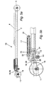
Fig.1 is a perspective view of a first embodiment of an arrangement for a roller ski of the first aspect of the invention. -
Fig. 2a is a side view of a first embodiment of an arrangement for a roller ski of the first aspect of the invention with the brake means in a non-active position. -
Fig. 2b is an enlarged side view of a detail of a first embodiment of an arrangement for a roller ski of the first aspect of the invention with the brake means in a non-active position. -
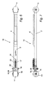
Fig. 3 is a top view of a first embodiment of an arrangement for a roller ski of the first aspect of the invention. -
Fig. 4 is a side view of a first embodiment of an arrangement for a roller ski of the first aspect of the invention with the brake means in an active position. -
Fig. 5a is a side view of a second embodiment of an arrangement for a roller ski of the first aspect of the invention with the brake means in a non-active position. -
Fig. 5b is an enlarged side view of a detail of a second embodiment of an arrangement for a roller ski of the first aspect of the invention with the brake means in a non-active position. -
Fig. 6 is a top view of a second embodiment of an arrangement for a roller ski of the first aspect of the invention. -
Fig. 7 is a side view of a second embodiment of an arrangement for a roller ski of the first aspect of the invention with the brake means in an active position. -
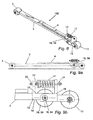
Fig.8 is a perspective view of a first embodiment of an arrangement for a roller ski of the second aspect of the invention. -
Fig. 9a is a side view of a first embodiment of an arrangement for a roller ski of the second aspect of the invention with the brake means in a non-active position. -
Fig. 9b is an enlarged side view of a detail of a first embodiment of an arrangement for a roller ski of the second aspect of the invention with the brake means in a non-active position. -
Fig. 10a is a side view of a second embodiment of an arrangement for a roller ski of the second aspect of the invention with the brake means in a non-active position. -
Fig. 10b is an enlarged side view of a detail of a second embodiment of an arrangement for a roller ski of the second aspect of the invention with the brake means in a non-active position. -
Fig. 11 is a side view of a second embodiment of an arrangement for a roller ski of the second aspect of the invention with the brake means in an active position. -
Fig. 12a is a side view of a third embodiment of an arrangement for a roller ski of the second aspect of the invention with the brake means in a non-active position. -
Fig. 12b is an enlarged side view of a detail of a third embodiment of an arrangement for a roller ski of the second aspect of the invention with the brake means in a non-active position. -
Fig. 13 is a top view of a third embodiment of an arrangement for a roller ski of the second aspect of the invention. - In a first embodiment of an arrangement of the first aspect of the invention, as shown in
figures 1 ,2a ,2b ,3 and 4 mounted to aroller ski 1 comprising anelongated body 2, aroller wheel 3 and a binding 4, an arrangement comprises a fixingelement 12 for fixing the arrangement to theroller ski 1. The fixingelement 12 is inserted into the hollowelongated body 2 of theroller ski 1. The fixingelement 12 is clamped to theroller ski 1 by means of abolt 12, as shown infigures 2 and4 . A pivotingelement 15 is connected to the fixingelement 12 through apivotal connection 16 constituted of a through bolt with lateral nuts. Other solutions are possible as well, such as two separate bolts, one at each side, bushings or similar. Afirst roller wheel 11 is mounted to the pivotingelement 15 by means of a wheel axle and two lateral nuts. Thefirst roller wheel 11 is mounted in bearings, such as ball bearings or plain bearings depending on the intended use. The arrangement further comprises a brake means 18 comprising a unidirectional roller means 19. The unidirectional roller means is arranged within a U-shaped part of the fixingelement 12 by means of a through bolt and lateral nuts. This provides for a reliable yet simple construction which is easy to access for inspection and maintenance. The unidirectional roller means 19 can be made from metal, plastics or rubber or any other material providing a required braking behaviour. Aspring housing 23 is arranged at the fixingelement 12. Within the spring housing 23 aresilient element 17, here in the form of a coil spring, is arranged with its longitudinal axis parallel to the longitudinal axis of theelongated body 2 of theroller ski 1. This construction brings about a number of advantages. It is possible to use resilient elements of almost any dimension, in contrast to the solution in the prior art where the length of the resilient element has to be adapted to the height of the interior of the roller ski. This allows for the use of reliable, easy to adjust resilient element. Theresilient element 17 acts on the fixingelement 12 via thespring housing 23 and on the pivotingelement 15 via abolt 21. Saidbolt 21 passing through an opening in the fixingelement 12 and thespring housing 23, as can be seen infigures 2 and4 . Thebolt 21 acts on the coil spring through a threadednut 22 which also can be used to adjust a level of pre-load in the coil spring. It should be noted that theresilient element 17 can be constituted by other elements than a coil spring, for example an elastomeric block or similar. Abolt 51 passes through an opening in the pivotingelement 15 and is threaded into the fixingelement 12.Bolt 51 acts as an adjustable position limiter for the pivotal movement of the pivotingelement 15. This is advantageous since it can be avoided that the pivotingelement 15 pivots too far and comes in contact with the brake means 18, causing unnecessary wear of the brake means 18. - The functioning of an arrangement according to the first aspect of the invention will now be discussed. In
figure 2a aroller ski 1 with an arrangement according to the invention is shown positioned on a ground surface S with the brake means 18 in a non-active position, i.e. the unidirectional roller means 19 is at a distance from thefirst roller wheel 11. When a downwardly directed force F (nor shown in the figures), i.e. directed from anupper side 13 of the fixingelement 12 towards alower side 14, which is strong enough to overcome the force exerted by theresilient element 17, is applied to the fixingelement 12, as for example done by a skier, not shown in the figures, during the kick phase of a diagonal stride, the pivotingelement 15 will rotate around the rotational axis ofpivotal connection 16 in a first direction, in this case clock-wise. Thefirst roller wheel 11, arranged at the pivotingelement 15, will thus travel substantially upwardly. If the force F is strong enough, thefirst roller wheel 11 will come in contact with the brake means 18, shown infigure 4 , which means that the brake means 18 reaches an active position and a brake effect will occur. The force required to overcome the resistance of the resilient element is also denoted threshold. This construction also provides for an increasing brake effect with increasing force. This means that if the force only just reaches the threshold, full brake effect will not be provided since the brake means 18 will barely touch thefirst roller wheel 11. With increasing force, thefirst roller wheel 11 will press harder against the brake means 18 and the brake effect will increase. The brake effect will depend upon the coefficient of friction between a brake surface of the brake means 18 and a tread of thefirst roller wheel 11. This effect is important since this is also the case when doing cross country skiing on snow. In this embodiment the brake means 18 comprises a unidirectional roller means 19 which means that it only will provide a brake effect in one direction and will allow thefirst roller wheel 11 to roll in the other direction. In order to provide skier with grip during a kick phase of a diagonal stride, the unidirectional roller means 19, when in an active position, will be arranged to restrain thefirst roller wheel 11 from rolling backwards and allow thefirst roller wheel 11 to continue rolling forwards. This also has the advantage that in a case where the brake means 18 unintentionally reaches an active position, for example if a skier rides over a sharp bump, thefirst roller wheel 11 will not suddenly brake, which could cause a skier to come to a fall. - In a second embodiment of an arrangement of the first aspect of the invention, as shown in
figures 5a, 5b ,6 and 7 mounted to aroller ski 10 comprising anelongated body 2, aroller wheel 3 and a binding 4, an arrangement comprises a brake means 18 in the form of abrake shoe 29 made from for example metal or plastics providing a required braking behaviour. The use of abrake shoe 29 provides for a very simple and reliable construction. Thebrake shoe 29 is arranged at one end of abolt 20 which is threaded into the fixingelement 12 and which passes through an opening in the pivotingelement 15. The threaded connection ofbolt 20 allows for adjusting of the position of thebrake shoe 29 which is advantageous in order to provide aroller ski 10 having the required characteristics. Other than the differences in the brake means 18 described above, the arrangement and the advantages thereof according to this second embodiment corresponds to previously described arrangement, referring tofigures 1 to 4 . - In a first embodiment of an arrangement of the second aspect of the invention, as shown in
figures 8, 9a and 9b mounted to aroller ski 100 comprising anelongated body 2, aroller wheel 3 and a binding 4, an arrangement comprises a fixingelement 12 for fixing the arrangement to theroller ski 100. The fixingelement 12 is inserted into the hollowelongated body 2 of the roller ski, similar to the fixing elements of the first aspect of the invention even though not shown explicitly infigures 8, 9a or 9b . A pivotingelement 15 is connected to the fixingelement 12 through apivotal connection 16. Afirst roller wheel 11 is mounted to the pivotingelement 15 by means of a wheel axle and two lateral nuts. The roller wheel is mounted in bearings, such as ball bearings or plain bearings depending on the intended use. The arrangement further comprises a brake means 18 comprising a second roller wheel 39, said second roller wheel 39 being unidirectional. In this embodiment, thepivotal connection 16 is constituted by a wheel axle of the second roller wheel 39. The pivotingmember 15 has two parallel side members each having a downwardly directed cut-out in which the wheel axle of the second roller wheel 39 is positioned, in that way providing thepivotal connection 16. The wheel axle is provided with threaded nuts outside of each side member. Other solutions are possible as well, such as providing the side members with holes instead of cut-outs. The wheel axle of the second roller wheel 39 may be fixed to the wheel or it can be a separate, loose axle. Aresilient element 17, here in the form of a coil spring, is arranged between the fixedelement 12 and the pivotingmember 15. Abolt 31 passes through the fixingelement 12, the pivotingmember 15 and theresilient element 17 respectively to hold the resilient element in place. An inner threadednut 32 together with washer is provided on thebolt 31 for adjusting a pre-load of theresilient element 17. An outer threadednut 33 is provided at an end of thebolt 31 to keep thebolt 31 in place. As with the arrangement according to the first aspect of the invention, theresilient element 17 is positioned with its longitudinal axis parallel to the longitudinal axis of theelongated body 2 of theroller ski 100. This construction brings about a number of advantages. It is possible to use resilient elements of almost any suitable dimension, in contrast to the solution in the prior art where the length of the resilient element has to be adapted to the height of the interior of the roller ski. This allows for the use of reliable and easy to adjust resilient element. It should be noted that theresilient element 17 can be constituted by other elements than a coil spring, for example an elastomeric block or similar. - The functioning of an arrangement according to the second aspect of the invention will now be discussed, referring to
figures 9a and 9b . In these figures aroller ski 100 with an arrangement according to the second aspect of the invention is shown positioned on a ground surface with the brake means 18 in a non-active position, i.e. the unidirectional second roller wheel 39 is at a distance from the ground surface. When a downwardly directed force F (not shown in the figure), i.e. directed from anupper side 13 of the fixingelement 12 towards alower side 14, which is strong enough to overcome the force exerted by theresilient element 17, is applied to the fixingelement 12, as for example done by a skier, not shown in the figures, during the kick phase of a diagonal stride, the pivotingelement 15 will rotate around the rotational axis ofpivotal connection 16 in a first direction, in this case counter clock-wise. The second roller wheel 39, arranged at the pivotingelement 15, will thus travel substantially downwardly. If the force F is strong enough, i.e. exceeding the threshold, the second roller wheel 39 will come in contact with the ground surface, which means that the brake means 18 reaches an active position and a brake effect will occur due to the unidirectional functioning of the second roller wheel 39. Similar to the arrangements according to the first aspect of the invention, the brake effect will increase with increasing force. The brake effect will depend on the force with which the second roller wheel 39 is pushed against the ground surface and the coefficient of friction between these two. Due to the unidirectional functioning of the second roller wheel 39 it will only provide a brake effect in one direction and will roll freely in the other direction. In order to provide skier with grip during a kick phase of a diagonal stride, the second roller wheel 39, when in an active position, will be arranged to restrain theroller ski 100 from rolling backwards and allow theroller ski 100 to continue rolling forwards. This also has the advantage that in a case where the brake means 18 unintentionally reaches an active position, for example if a skier rides over a sharp bump, theroller ski 100 will not suddenly brake, which could cause a skier to come to a fall. - A second embodiment of an arrangement of the second aspect of the invention, is shown in
figures 10a, 10b and 11 . In this embodiment, the brake means 18, which comprises a second roller wheel of the unidirectional type, is mounted to the fixingelement 12. Afirst roller wheel 11 is arranged at a pivotingelement 15. The separate construction details of this embodiment correspond to those already described above. The functioning of this second embodiment of an arrangement of the second aspect of the invention correspond to that of the embodiments previously described. Accordingly, if a downwardly directed force F, i.e. directed from anupper side 13 of the fixingelement 12 towards alower side 14, which is strong enough to overcome the force exerted by theresilient element 17, is applied to the fixingelement 12, as for example done by a skier, not shown in the figures, during the kick phase of a diagonal stride, the pivotingelement 15 will rotate around the rotational axis ofpivotal connection 16 in a first direction, in this case clock-wise. The second roller wheel 49, arranged at the fixingelement 15, will thus travel substantially downwardly. If the force F is strong enough, i.e. exceeding the threshold, the second roller wheel 49 will come in contact with the ground surface, which means that the brake means 18 reaches an active position and a brake effect will occur due to the unidirectional functioning of the second roller wheel 49. Again, the brake effect will increase with increasing force. The brake effect will depend on the force with which the second roller wheel 49 is pushed against the ground surface and the coefficient of friction between these two. Due to the unidirectional functioning of the second roller wheel 49 it will only provide a brake effect in one direction and will roll freely in the other direction. In order to provide skier with grip during a kick phase of a diagonal stride, the second roller wheel 49, when in an active position, will be arranged to restrain theroller ski 100 from rolling backwards and allow theroller ski 100 to continue rolling forwards. - A third embodiment of an arrangement of the second aspect of the invention, is shown in
figures 12a, 12b and 13 . The arrangement according to this embodiment differs from those previously described primarily in two matters. Firstly, in order to provide aroller ski 300 which is easy to use also to people who are not used to roller skiing, the arrangement comprises two separate coaxial second roller wheels of the unidirectional type and two separate coaxialfirst roller wheels 11 are mounted to the pivotingelement 15. The use of separate coaxial roller wheels requires less balance skills from a skier. Secondly, theresilient element 17 has been mounted inside the fixingelement 12. The fixingelement 12 in turn is mounted within the recess of theelongated body 2 of theroller ski 300. This provides for excellent protection of theresilient element 17 from dirt, water and similar. A pre-load of the resilient element can still be adjusted by means of bolt-head 36 ofbolt 31.Bolt 31 is threaded and passes through theresilient element 17 and intoblock 35 having an internal thread corresponding to that ofbolt 31. By turningbolt 31 the longitudinal position ofblock 35 can be adjusted and thereby the pre-load ofresilient element 17. Apart from these differences, the arrangement according to this third embodiments corresponds to those previously described. - The tyre tread of the roller wheels described herein is preferably made from rubber or materials having similar properties whereas wheel axles, bolts and nuts preferably are made from metal, such as steel alloys. The elongated body of the roller ski, the fixing elements and the pivoting elements are preferably made from suitable metal, such as steel or aluminium and alloys thereof but composite materials are also possible to use in this respect. The resilient elements can be made from metal coil springs or elastomeric blocks. Instead of mounting the fixing element within a recess in the elongated body of the roller ski, it is also possible to fit the end of an elongated body of the roller ski within a recess provided in the fixing element.
Claims (15)
- An arrangement for a roller ski (1), said arrangement comprising a first roller wheel (11), a fixing element (12) for attaching the arrangement to an elongated body (2) of a roller ski (1), said fixing element (12) having an upper side (13) and a lower side (14), a pivoting element (15) connected to the fixing element (12) by means of a pivotal connection (16), said pivotal connection (16) having a rotational axis perpendicular to a longitudinal axis of the elongated body (2) of the roller ski (1), the arrangement further comprising a resilient element (17) coupled to the fixing element (12) and the pivoting element (15), said resilient element (17) having a longitudinal axis parallel to the longitudinal axis of the elongated body (2) of the roller ski (1), wherein the resilient element (17) biases the pivoting element (15) in a first direction, and wherein the pivoting element (15) is arranged to move in a second direction, opposite to said first direction, when a force is applied to the fixing element (12), said force being directed from the upper side (13) of the fixing element (12) towards the lower side (14) of the fixing element (12) and substantially perpendicular to the rotational axis of the pivotal connection (16), wherein the arrangement further comprises a brake means (18), said brake means (18) approaching a non-active position as the pivoting element (15) moves in said first direction and said brake means (18) approaching an active position as the pivoting element (15) moves in said second direction and wherein said brake means (18) is in said non-active position when the force is below a predetermined threshold and said brake means (18) reaches an active position when the force exceeds the predetermined threshold, wherein a braking effect increases with increasing force.
- Arrangement for a roller ski (1) according to claim 1, wherein the brake means (18) abuts said first roller wheel (11) when in said active position.
- Arrangement for a roller ski (1) according to claim 2, wherein the brake means comprises a unidirectional roller means (19, 39, 49, 59).
- Arrangement for a roller ski (1) according to claim 2, wherein the brake means (18) comprises a brake shoe (29).
- Arrangement for a roller ski (1) according to any of claims 2 to 4, wherein the first roller wheel (11) is arranged at the pivoting element (15) and the brake means (18) is arranged at the fixing element (12) and wherein the pivoting element (15) will move in said second direction when the force exceeds the predetermined threshold causing the first roller wheel (11) arranged at the pivoting element (15) to abut the brake means (18).
- Arrangement for a roller ski (1) according to any of claims 2 to 5, wherein the brake means (18) is arranged at the fixing element (12) by means of a threaded connection such that the position of the brake means (18) can be adjusted.
- Arrangement for a roller ski (1) according to claim 1, wherein the brake means (18), when in use, abuts the ground surface when in said active position.
- Arrangement for a roller ski (1) according to claim 7, wherein the brake means (18) comprises a second roller wheel (39, 49, 59), said second roller wheel (39, 49, 59) being unidirectional.
- Arrangement for a roller ski (1) according to claim 8, wherein the pivotal connection (16) coincide with a wheel centre of the second roller wheel (39, 49, 59).
- Arrangement for a roller ski (1) according to any of the preceding claims, wherein the resilient element (17) are provided at the upper surface (13) of the fixing element (12).
- Arrangement for a roller ski (1) according to any of claims 1 to 9, wherein the resilient element (17) are provided inside the fixing element (12).
- Arrangement for a roller ski (1) according to any of the preceding claims, wherein a pre-load of the resilient element (17) is adjustable.
- Arrangement for a roller ski (1) according to claim any of the preceding claims, wherein the fixing element (12) is arranged to be inserted into a recess of an elongated body (2) of a roller ski (1).
- Arrangement for a roller ski (1) according to any of claims 1 to 12, wherein the fixing element (12) is arranged to enclose an end of an elongated body (2) of a roller ski (1).
- Roller ski (1) characterized in that it comprises at least one arrangement according to any of claims 1-14.
Priority Applications (2)
| Application Number | Priority Date | Filing Date | Title |
|---|---|---|---|
| EP20100171857 EP2418006B1 (en) | 2010-08-04 | 2010-08-04 | Arrangement for a roller ski and a roller ski |
| PCT/EP2011/054796 WO2012016718A1 (en) | 2010-08-04 | 2011-03-29 | Arrangement for a roller ski and a roller ski |
Applications Claiming Priority (1)
| Application Number | Priority Date | Filing Date | Title |
|---|---|---|---|
| EP20100171857 EP2418006B1 (en) | 2010-08-04 | 2010-08-04 | Arrangement for a roller ski and a roller ski |
Publications (2)
| Publication Number | Publication Date |
|---|---|
| EP2418006A1 EP2418006A1 (en) | 2012-02-15 |
| EP2418006B1 true EP2418006B1 (en) | 2013-04-24 |
Family
ID=43415360
Family Applications (1)
| Application Number | Title | Priority Date | Filing Date |
|---|---|---|---|
| EP20100171857 Not-in-force EP2418006B1 (en) | 2010-08-04 | 2010-08-04 | Arrangement for a roller ski and a roller ski |
Country Status (2)
| Country | Link |
|---|---|
| EP (1) | EP2418006B1 (en) |
| WO (1) | WO2012016718A1 (en) |
Families Citing this family (4)
| Publication number | Priority date | Publication date | Assignee | Title |
|---|---|---|---|---|
| NO334042B1 (en) * | 2010-11-01 | 2013-11-25 | Hiturn As | Roller skating device |
| DE202015100864U1 (en) | 2015-02-23 | 2015-03-04 | Siegfried Rieckhoff Electronic E.K. | Rollski |
| CN109050645A (en) * | 2018-07-18 | 2018-12-21 | 广州市勇源冰雪运动用品有限公司 | A kind of Skis for use on land |
| WO2022000029A1 (en) * | 2020-06-30 | 2022-01-06 | Maxm Skate Pty Ltd | An improved medical leg support arrangement |
Family Cites Families (2)
| Publication number | Priority date | Publication date | Assignee | Title |
|---|---|---|---|---|
| SE513173C2 (en) * | 1999-07-09 | 2000-07-24 | Robert Stake | Roller ski, has transmission system formed by drive belts and gear wheels to ensure conversion of backwards foot plate movement into positive ski movement |
| US20080030014A1 (en) | 2006-08-04 | 2008-02-07 | Pate Warren M | Diagonal-stride-simulating roller ski |
-
2010
- 2010-08-04 EP EP20100171857 patent/EP2418006B1/en not_active Not-in-force
-
2011
- 2011-03-29 WO PCT/EP2011/054796 patent/WO2012016718A1/en not_active Ceased
Also Published As
| Publication number | Publication date |
|---|---|
| EP2418006A1 (en) | 2012-02-15 |
| WO2012016718A1 (en) | 2012-02-09 |
Similar Documents
| Publication | Publication Date | Title |
|---|---|---|
| US9821215B2 (en) | Suspension system for a skateboard or other rider platform | |
| US8469377B2 (en) | Truck assembly | |
| US7413200B2 (en) | Skateboard truck with single-pin, pivotal, reversible attachment between axel and base plate, and means of improving a user's shredding capabilities through use of the skateboard truck with single-pin, pivotal attachment between axel and base plate | |
| US8857823B2 (en) | Coupling means | |
| US20150097352A1 (en) | Suspension system for a skateboard or other rider platform | |
| US8684370B2 (en) | Skateboard truck | |
| US20130175774A1 (en) | Skateboard truck and caster with suspension mechanism | |
| EP2418006A1 (en) | Arrangement for a roller ski and a roller ski | |
| US8292311B2 (en) | Skateboard truck | |
| EP2961499B1 (en) | Skateboard truck and caster with suspension mechanism | |
| CA2867208C (en) | Suspension roller ski | |
| US20130300098A1 (en) | Roller ski | |
| US9504903B2 (en) | Braking apparatus for a recreational riding board apparatus | |
| US6343803B1 (en) | Skateboard and related apparatus | |
| US20110272903A1 (en) | Skateboard Wheel and Method of Maneuvering Therewith | |
| US20080030014A1 (en) | Diagonal-stride-simulating roller ski | |
| WO2008138019A1 (en) | Roller skate and skate board | |
| WO2002040116A1 (en) | Rollerboard for road-skiing | |
| US20070170677A1 (en) | Spring | |
| US11565168B2 (en) | Skateboard systems and methods | |
| WO2015066749A1 (en) | A swing arm suspension and steering skateboard | |
| US20080012249A1 (en) | In line roller skate with shock absorbent suspension | |
| EP4469173B1 (en) | A shock absorber system connectable to a roller ski wheel shaft | |
| DE20206709U1 (en) | Single track roller skate | |
| DE102013224611B4 (en) | Skiroller |
Legal Events
| Date | Code | Title | Description |
|---|---|---|---|
| AK | Designated contracting states |
Kind code of ref document: A1 Designated state(s): AL AT BE BG CH CY CZ DE DK EE ES FI FR GB GR HR HU IE IS IT LI LT LU LV MC MK MT NL NO PL PT RO SE SI SK SM TR |
|
| AX | Request for extension of the european patent |
Extension state: BA ME RS |
|
| PUAI | Public reference made under article 153(3) epc to a published international application that has entered the european phase |
Free format text: ORIGINAL CODE: 0009012 |
|
| 17P | Request for examination filed |
Effective date: 20120815 |
|
| GRAP | Despatch of communication of intention to grant a patent |
Free format text: ORIGINAL CODE: EPIDOSNIGR1 |
|
| RIC1 | Information provided on ipc code assigned before grant |
Ipc: A63C 5/035 20060101AFI20121106BHEP |
|
| GRAS | Grant fee paid |
Free format text: ORIGINAL CODE: EPIDOSNIGR3 |
|
| GRAA | (expected) grant |
Free format text: ORIGINAL CODE: 0009210 |
|
| AK | Designated contracting states |
Kind code of ref document: B1 Designated state(s): AL AT BE BG CH CY CZ DE DK EE ES FI FR GB GR HR HU IE IS IT LI LT LU LV MC MK MT NL NO PL PT RO SE SI SK SM TR |
|
| REG | Reference to a national code |
Ref country code: GB Ref legal event code: FG4D |
|
| REG | Reference to a national code |
Ref country code: CH Ref legal event code: EP |
|
| REG | Reference to a national code |
Ref country code: AT Ref legal event code: REF Ref document number: 608236 Country of ref document: AT Kind code of ref document: T Effective date: 20130515 |
|
| REG | Reference to a national code |
Ref country code: IE Ref legal event code: FG4D |
|
| REG | Reference to a national code |
Ref country code: SE Ref legal event code: TRGR |
|
| REG | Reference to a national code |
Ref country code: DE Ref legal event code: R096 Ref document number: 602010006507 Country of ref document: DE Effective date: 20130627 |
|
| REG | Reference to a national code |
Ref country code: AT Ref legal event code: MK05 Ref document number: 608236 Country of ref document: AT Kind code of ref document: T Effective date: 20130424 |
|
| REG | Reference to a national code |
Ref country code: LT Ref legal event code: MG4D |
|
| REG | Reference to a national code |
Ref country code: NL Ref legal event code: VDEP Effective date: 20130424 |
|
| PG25 | Lapsed in a contracting state [announced via postgrant information from national office to epo] |
Ref country code: AT Free format text: LAPSE BECAUSE OF FAILURE TO SUBMIT A TRANSLATION OF THE DESCRIPTION OR TO PAY THE FEE WITHIN THE PRESCRIBED TIME-LIMIT Effective date: 20130424 Ref country code: FI Free format text: LAPSE BECAUSE OF FAILURE TO SUBMIT A TRANSLATION OF THE DESCRIPTION OR TO PAY THE FEE WITHIN THE PRESCRIBED TIME-LIMIT Effective date: 20130424 Ref country code: NO Free format text: LAPSE BECAUSE OF FAILURE TO SUBMIT A TRANSLATION OF THE DESCRIPTION OR TO PAY THE FEE WITHIN THE PRESCRIBED TIME-LIMIT Effective date: 20130724 Ref country code: SI Free format text: LAPSE BECAUSE OF FAILURE TO SUBMIT A TRANSLATION OF THE DESCRIPTION OR TO PAY THE FEE WITHIN THE PRESCRIBED TIME-LIMIT Effective date: 20130424 Ref country code: IS Free format text: LAPSE BECAUSE OF FAILURE TO SUBMIT A TRANSLATION OF THE DESCRIPTION OR TO PAY THE FEE WITHIN THE PRESCRIBED TIME-LIMIT Effective date: 20130824 Ref country code: LT Free format text: LAPSE BECAUSE OF FAILURE TO SUBMIT A TRANSLATION OF THE DESCRIPTION OR TO PAY THE FEE WITHIN THE PRESCRIBED TIME-LIMIT Effective date: 20130424 Ref country code: PT Free format text: LAPSE BECAUSE OF FAILURE TO SUBMIT A TRANSLATION OF THE DESCRIPTION OR TO PAY THE FEE WITHIN THE PRESCRIBED TIME-LIMIT Effective date: 20130826 Ref country code: BE Free format text: LAPSE BECAUSE OF FAILURE TO SUBMIT A TRANSLATION OF THE DESCRIPTION OR TO PAY THE FEE WITHIN THE PRESCRIBED TIME-LIMIT Effective date: 20130424 Ref country code: ES Free format text: LAPSE BECAUSE OF FAILURE TO SUBMIT A TRANSLATION OF THE DESCRIPTION OR TO PAY THE FEE WITHIN THE PRESCRIBED TIME-LIMIT Effective date: 20130804 Ref country code: GR Free format text: LAPSE BECAUSE OF FAILURE TO SUBMIT A TRANSLATION OF THE DESCRIPTION OR TO PAY THE FEE WITHIN THE PRESCRIBED TIME-LIMIT Effective date: 20130725 |
|
| PG25 | Lapsed in a contracting state [announced via postgrant information from national office to epo] |
Ref country code: BG Free format text: LAPSE BECAUSE OF FAILURE TO SUBMIT A TRANSLATION OF THE DESCRIPTION OR TO PAY THE FEE WITHIN THE PRESCRIBED TIME-LIMIT Effective date: 20130724 Ref country code: PL Free format text: LAPSE BECAUSE OF FAILURE TO SUBMIT A TRANSLATION OF THE DESCRIPTION OR TO PAY THE FEE WITHIN THE PRESCRIBED TIME-LIMIT Effective date: 20130424 Ref country code: CY Free format text: LAPSE BECAUSE OF FAILURE TO SUBMIT A TRANSLATION OF THE DESCRIPTION OR TO PAY THE FEE WITHIN THE PRESCRIBED TIME-LIMIT Effective date: 20130424 Ref country code: HR Free format text: LAPSE BECAUSE OF FAILURE TO SUBMIT A TRANSLATION OF THE DESCRIPTION OR TO PAY THE FEE WITHIN THE PRESCRIBED TIME-LIMIT Effective date: 20130424 Ref country code: LV Free format text: LAPSE BECAUSE OF FAILURE TO SUBMIT A TRANSLATION OF THE DESCRIPTION OR TO PAY THE FEE WITHIN THE PRESCRIBED TIME-LIMIT Effective date: 20130424 |
|
| PG25 | Lapsed in a contracting state [announced via postgrant information from national office to epo] |
Ref country code: EE Free format text: LAPSE BECAUSE OF FAILURE TO SUBMIT A TRANSLATION OF THE DESCRIPTION OR TO PAY THE FEE WITHIN THE PRESCRIBED TIME-LIMIT Effective date: 20130424 Ref country code: DK Free format text: LAPSE BECAUSE OF FAILURE TO SUBMIT A TRANSLATION OF THE DESCRIPTION OR TO PAY THE FEE WITHIN THE PRESCRIBED TIME-LIMIT Effective date: 20130424 Ref country code: SK Free format text: LAPSE BECAUSE OF FAILURE TO SUBMIT A TRANSLATION OF THE DESCRIPTION OR TO PAY THE FEE WITHIN THE PRESCRIBED TIME-LIMIT Effective date: 20130424 Ref country code: CZ Free format text: LAPSE BECAUSE OF FAILURE TO SUBMIT A TRANSLATION OF THE DESCRIPTION OR TO PAY THE FEE WITHIN THE PRESCRIBED TIME-LIMIT Effective date: 20130424 |
|
| PG25 | Lapsed in a contracting state [announced via postgrant information from national office to epo] |
Ref country code: IT Free format text: LAPSE BECAUSE OF FAILURE TO SUBMIT A TRANSLATION OF THE DESCRIPTION OR TO PAY THE FEE WITHIN THE PRESCRIBED TIME-LIMIT Effective date: 20130424 Ref country code: NL Free format text: LAPSE BECAUSE OF FAILURE TO SUBMIT A TRANSLATION OF THE DESCRIPTION OR TO PAY THE FEE WITHIN THE PRESCRIBED TIME-LIMIT Effective date: 20130424 Ref country code: RO Free format text: LAPSE BECAUSE OF FAILURE TO SUBMIT A TRANSLATION OF THE DESCRIPTION OR TO PAY THE FEE WITHIN THE PRESCRIBED TIME-LIMIT Effective date: 20130424 |
|
| PLBE | No opposition filed within time limit |
Free format text: ORIGINAL CODE: 0009261 |
|
| STAA | Information on the status of an ep patent application or granted ep patent |
Free format text: STATUS: NO OPPOSITION FILED WITHIN TIME LIMIT |
|
| REG | Reference to a national code |
Ref country code: DE Ref legal event code: R119 Ref document number: 602010006507 Country of ref document: DE |
|
| 26N | No opposition filed |
Effective date: 20140127 |
|
| PG25 | Lapsed in a contracting state [announced via postgrant information from national office to epo] |
Ref country code: MC Free format text: LAPSE BECAUSE OF FAILURE TO SUBMIT A TRANSLATION OF THE DESCRIPTION OR TO PAY THE FEE WITHIN THE PRESCRIBED TIME-LIMIT Effective date: 20130424 Ref country code: DE Free format text: LAPSE BECAUSE OF NON-PAYMENT OF DUE FEES Effective date: 20140301 |
|
| REG | Reference to a national code |
Ref country code: DE Ref legal event code: R097 Ref document number: 602010006507 Country of ref document: DE Effective date: 20140127 |
|
| REG | Reference to a national code |
Ref country code: IE Ref legal event code: MM4A |
|
| REG | Reference to a national code |
Ref country code: FR Ref legal event code: ST Effective date: 20140430 |
|
| REG | Reference to a national code |
Ref country code: DE Ref legal event code: R119 Ref document number: 602010006507 Country of ref document: DE Effective date: 20140301 |
|
| PG25 | Lapsed in a contracting state [announced via postgrant information from national office to epo] |
Ref country code: IE Free format text: LAPSE BECAUSE OF NON-PAYMENT OF DUE FEES Effective date: 20130804 |
|
| PG25 | Lapsed in a contracting state [announced via postgrant information from national office to epo] |
Ref country code: FR Free format text: LAPSE BECAUSE OF NON-PAYMENT OF DUE FEES Effective date: 20130902 |
|
| REG | Reference to a national code |
Ref country code: CH Ref legal event code: PL |
|
| GBPC | Gb: european patent ceased through non-payment of renewal fee |
Effective date: 20140804 |
|
| PG25 | Lapsed in a contracting state [announced via postgrant information from national office to epo] |
Ref country code: LI Free format text: LAPSE BECAUSE OF NON-PAYMENT OF DUE FEES Effective date: 20140831 Ref country code: CH Free format text: LAPSE BECAUSE OF NON-PAYMENT OF DUE FEES Effective date: 20140831 |
|
| PG25 | Lapsed in a contracting state [announced via postgrant information from national office to epo] |
Ref country code: SM Free format text: LAPSE BECAUSE OF FAILURE TO SUBMIT A TRANSLATION OF THE DESCRIPTION OR TO PAY THE FEE WITHIN THE PRESCRIBED TIME-LIMIT Effective date: 20130424 |
|
| PG25 | Lapsed in a contracting state [announced via postgrant information from national office to epo] |
Ref country code: TR Free format text: LAPSE BECAUSE OF FAILURE TO SUBMIT A TRANSLATION OF THE DESCRIPTION OR TO PAY THE FEE WITHIN THE PRESCRIBED TIME-LIMIT Effective date: 20130424 Ref country code: MT Free format text: LAPSE BECAUSE OF FAILURE TO SUBMIT A TRANSLATION OF THE DESCRIPTION OR TO PAY THE FEE WITHIN THE PRESCRIBED TIME-LIMIT Effective date: 20130424 |
|
| PG25 | Lapsed in a contracting state [announced via postgrant information from national office to epo] |
Ref country code: HU Free format text: LAPSE BECAUSE OF FAILURE TO SUBMIT A TRANSLATION OF THE DESCRIPTION OR TO PAY THE FEE WITHIN THE PRESCRIBED TIME-LIMIT; INVALID AB INITIO Effective date: 20100804 Ref country code: LU Free format text: LAPSE BECAUSE OF NON-PAYMENT OF DUE FEES Effective date: 20130804 Ref country code: MK Free format text: LAPSE BECAUSE OF FAILURE TO SUBMIT A TRANSLATION OF THE DESCRIPTION OR TO PAY THE FEE WITHIN THE PRESCRIBED TIME-LIMIT Effective date: 20130424 Ref country code: GB Free format text: LAPSE BECAUSE OF NON-PAYMENT OF DUE FEES Effective date: 20140804 |
|
| PGFP | Annual fee paid to national office [announced via postgrant information from national office to epo] |
Ref country code: SE Payment date: 20170831 Year of fee payment: 8 |
|
| PG25 | Lapsed in a contracting state [announced via postgrant information from national office to epo] |
Ref country code: AL Free format text: LAPSE BECAUSE OF FAILURE TO SUBMIT A TRANSLATION OF THE DESCRIPTION OR TO PAY THE FEE WITHIN THE PRESCRIBED TIME-LIMIT Effective date: 20130424 |
|
| REG | Reference to a national code |
Ref country code: SE Ref legal event code: EUG |
|
| PG25 | Lapsed in a contracting state [announced via postgrant information from national office to epo] |
Ref country code: SE Free format text: LAPSE BECAUSE OF NON-PAYMENT OF DUE FEES Effective date: 20180805 |