EP2417958A1 - Adaptor for connecting a feeding container to an enteral feeding coupling, in particular for a baby bottle feeding assembly - Google Patents
Adaptor for connecting a feeding container to an enteral feeding coupling, in particular for a baby bottle feeding assembly Download PDFInfo
- Publication number
- EP2417958A1 EP2417958A1 EP10008315A EP10008315A EP2417958A1 EP 2417958 A1 EP2417958 A1 EP 2417958A1 EP 10008315 A EP10008315 A EP 10008315A EP 10008315 A EP10008315 A EP 10008315A EP 2417958 A1 EP2417958 A1 EP 2417958A1
- Authority
- EP
- European Patent Office
- Prior art keywords
- adaptor
- feeding
- supporting member
- coupling
- sealing
- Prior art date
- Legal status (The legal status is an assumption and is not a legal conclusion. Google has not performed a legal analysis and makes no representation as to the accuracy of the status listed.)
- Granted
Links
- 230000008878 coupling Effects 0.000 title claims abstract description 39
- 238000010168 coupling process Methods 0.000 title claims abstract description 39
- 238000005859 coupling reaction Methods 0.000 title claims abstract description 39
- 238000007789 sealing Methods 0.000 claims abstract description 71
- 239000012530 fluid Substances 0.000 claims description 4
- 239000011888 foil Substances 0.000 claims description 3
- 239000000463 material Substances 0.000 description 9
- 238000000465 moulding Methods 0.000 description 2
- 239000003566 sealing material Substances 0.000 description 2
- 238000001746 injection moulding Methods 0.000 description 1
- 239000007788 liquid Substances 0.000 description 1
- 239000000203 mixture Substances 0.000 description 1
- 230000000474 nursing effect Effects 0.000 description 1
- 239000012858 resilient material Substances 0.000 description 1
Images



Classifications
-
- A—HUMAN NECESSITIES
- A61—MEDICAL OR VETERINARY SCIENCE; HYGIENE
- A61J—CONTAINERS SPECIALLY ADAPTED FOR MEDICAL OR PHARMACEUTICAL PURPOSES; DEVICES OR METHODS SPECIALLY ADAPTED FOR BRINGING PHARMACEUTICAL PRODUCTS INTO PARTICULAR PHYSICAL OR ADMINISTERING FORMS; DEVICES FOR ADMINISTERING FOOD OR MEDICINES ORALLY; BABY COMFORTERS; DEVICES FOR RECEIVING SPITTLE
- A61J9/00—Feeding-bottles in general
-
- A—HUMAN NECESSITIES
- A61—MEDICAL OR VETERINARY SCIENCE; HYGIENE
- A61J—CONTAINERS SPECIALLY ADAPTED FOR MEDICAL OR PHARMACEUTICAL PURPOSES; DEVICES OR METHODS SPECIALLY ADAPTED FOR BRINGING PHARMACEUTICAL PRODUCTS INTO PARTICULAR PHYSICAL OR ADMINISTERING FORMS; DEVICES FOR ADMINISTERING FOOD OR MEDICINES ORALLY; BABY COMFORTERS; DEVICES FOR RECEIVING SPITTLE
- A61J1/00—Containers specially adapted for medical or pharmaceutical purposes
- A61J1/14—Details; Accessories therefor
- A61J1/1475—Inlet or outlet ports
-
- A—HUMAN NECESSITIES
- A61—MEDICAL OR VETERINARY SCIENCE; HYGIENE
- A61J—CONTAINERS SPECIALLY ADAPTED FOR MEDICAL OR PHARMACEUTICAL PURPOSES; DEVICES OR METHODS SPECIALLY ADAPTED FOR BRINGING PHARMACEUTICAL PRODUCTS INTO PARTICULAR PHYSICAL OR ADMINISTERING FORMS; DEVICES FOR ADMINISTERING FOOD OR MEDICINES ORALLY; BABY COMFORTERS; DEVICES FOR RECEIVING SPITTLE
- A61J15/00—Feeding-tubes for therapeutic purposes
Definitions
- the invention relates to an adaptor for connecting a feeding container to an enteral feeding coupling, in particular for a baby bottle feeding assembly.
- the adaptor of the present invention in particular is used in the field of medical supplies and nursing care.
- patients are fed through a feeding container connected to a feeding set or feeding assembly which is connected to the patient via a feeding conduit in order to feed the patient with a liquid contained in the feeding container.
- a baby bottle can be used for the feeding container.
- the feeding container or baby bottle can be purchased from many different manufacturers and, thus, there is a broad range of different sizes and diameters of the feeding containers and their openings.
- the above object is achieved by an adaptor according to claim 1.
- the adaptor comprises a supporting member for connection with the feeding container, a sealing which is fastened to the supporting member suitable for providing fluid-tight connection between the adaptor and the feeding container and an end section suitable for connecting the adaptor to the feeding coupling.
- the adapter is configured to cooperate with a range of different sizes of feeding containers and/or with a range of different diameters for the opening of the feeding containers.
- the sealing is shaped and/or fixed to the adaptor in such a manner that the adaptor can cooperate with different sizes of the opening of the feeding container.
- the sealing is fastened to the supporting member in an area of the supporting member suitable for providing a fluid-tight connection between the adaptor and the feeding container and/or suitable for use for different sizes of the opening of the feeding container.
- the sealing comprises at least one sealing member.
- the sealing member can be formed as a ring, annular or plate-like etc.
- the at least one sealing member can be connected to the lower side, the upper side and/or the face side of the supporting member. The connection can be made by means of moulding the sealing material onto or over the supporting member, preferably the supporting plate.
- the sealing member can also be designated as sealing portion, sealing unit or gasket. If in the following the sealing itself, the sealing member or features thereof are mentioned, then only one sealing member, the sole sealing member, several sealing members or all sealing members can have the features and/or characteristics mentioned.
- the sealing member is integrally formed with the supporting member.
- the sealing member is moulded at least partially over or to the supporting member.
- sealing member and supporting member build a one-piece structure which is produced by moulding a sealing material on or over the preformed supporting member made of a rigid material in order to secure the sealing member to the supporting member.
- the supporting member is made of a rigid plastic material and the sealing member is made of a resilient material.
- the adaptor with the supporting member, the sealing member and the end section as a one-part member or element.
- at least the supporting member is produced by means of injection moulding.
- the supporting member can be a base or plate, in particular in form of an annular ring.
- the sealing member extends substantially parallel to the supporting member or in an inclined direction from the supporting member.
- the sealing member extends in a direction from the supporting member to include an angle of more than 90°, for example in the range of 91° to 135°.
- the adapter for feeding containers having different opening diameters.
- the sealing member is tapered and/or is shaped annular. To simplify the placement of the adapter on the opening side of the feeding container, the free end of the sealing member is tapered.
- the adaptor comprises an intermediate section between the supporting member and the end section.
- the intermediate section can be formed annular or can be provided with a base plate and a wall extending form the base plate. Furthermore, the intermediate section can build a shoulder. In general, the intermediate section is formed to improve the rigidity of the adapter.
- a thin layer which can be pierced through when the feeding coupling is connected to the adaptor.
- the thin layer is connected to the intermediate section and/or the supporting member.
- a film or foil, especially made of plastic material is used for the thin layer.
- a fastening element is provided for detachably or removably fastening the adaptor to the feeding container.
- the fastening element can be integrally formed with the supporting member or can be separate from the supporting member, in particular shaped as a cap.
- the fastening element comprises a threaded section for engaging a threaded section of the feeding container. This enables a screw connection of the feeding container and the adaptor.
- the end section can comprise a threaded section for engaging a threaded section of the feeding coupling.
- the feeding coupling comprises a tube having a feeding channel in order to allow a fluid connection between the feeding container and the feeding conduit.
- the tube has a first end extending in the area of the feeding container and a second end extending up to the outer end of the feeding coupling adjacent to the feeding conduit.
- the first end of the tube can have a tapered and/or sharp shape in order to pierce through the thin layer when the feeding coupling is connected to the adaptor.
- the thin layer of the adapter allows a fluid-tight seal of the feeding container closed with the adaptor mounted at the opening.
- the feeding coupling comprises a first end portion for fastening the feeding coupling to the end section of the adaptor and a second end portion for connecting a feeding conduit to the feeding coupling.
- the feeding coupling comprises a threaded section for engaging the threaded section of the end section.
- the present invention provides an adaptor for a quick and fluid-tight connection between a feeding container, in particular a baby bottle, and a feeding coupling, in particular a feeding set.
- the sealing is made of a softer material than the supporting member and the softer material is over moulded onto the harder material of the supporting member.
- the sealing member can be tapered so as to allow for a seal within different diameter of neck bottles.
- the thin layer allows for a mixture to be mixed in the feeding container if required before the feeding coupling is connected to the adaptor.
- a cap can be used as a fastening element.
- Fig. 1 schematically shows a feeding coupling 80 connected to a feeding container 70 by means of an adaptor 10 according to the present invention.
- the feeding container 70 is a baby bottle having an opening 72 at the upper side 74.
- the feeding coupling 80 can be connected with a feeding conduit 90 (cf. Fig. 2 ) to feed a patient with a fluid contained in the feeding container 70.
- the feeding container 70 is mounted such that it hangs downward.
- the adaptor 10 comprises a supporting member 20 for connection with the feeding container 70, a sealing 30 which is fastened to the supporting member 20 in an area of the supporting member 20 suitable for providing a fluid-tight connection between the adaptor 10 and the feeding container 70 and an end section 50 suitable for connecting the adaptor 10 to the feeding coupling 80.
- an intermediate section 40 between the supporting member 20 and the end section 50.
- the intermediate section 40 is made of the same rigid plastic material as the supporting member 20 and the end section 50.
- a fastening element 60 shaped as a cap and having a base plate 62 and a wall 64 for detachably fastening the adaptor 10 to the feeding container 70 can be taken from Fig. 1 and 2 .
- the wall 64 is provided with a threaded section 66 for engaging with a threaded section 79 on a outside 78 of the feeding container 70.
- the supporting member 20, the sealing 30, the intermediate section 40 and the end section 50 are shaped annular.
- the supporting member 20 comprises a supporting plate or ring 22 which is applied on a rim 76 at the upper side 74 of the feeding container 70 around the opening 72.
- the sealing 30 comprises an annular shaped sealing member 31 having a first end 32 which is fixed to the supporting plate 22 and a second end 33 which is a free end extending into the interior of the feeding container 70.
- the sealing member 31 is moulded at least partially over or moulded to the supporting member 20 in an area of the supporting plate 22 suitable for providing a fluid-tight connection between the adaptor 10 and the feeding container 70.
- the sealing member 31 extends substantially in a longitudinal direction L of the adaptor 10.
- “Substantially” means in the present embodiment that the sealing member 31 extends in an inclined direction including an angle ⁇ between the extension of the sealing member 31 and the extension of the supporting plate 22. Preferably this angle ⁇ is more than 90°, in particular between about 91° and about 135°.
- the second end 33 is a tapered end.
- the configuration of the inclined extension and/or the tapered end 33 of the sealing member 31 enables the adaptor 10 to cooperate with a range of different diameters for the opening 72 and/or with a range of different sizes of feeding containers 70.
- the sealing member 31 is shaped and/or fixed to the adaptor 10 in such a manner that the adaptor 10 can cooperate with different sizes of the opening 72 of the feeding container 70.
- the intermediate section 40 comprises a base 42, in particular shaped as an annular plate, and a wall 43 formed integrally with the base 42 and made of the same material.
- the wall 43 extends substantially parallel to the longitudinal direction L and the base 42 extends in the radial direction R parallel to the supporting plate 22. This shape improves the stability of the whole adaptor 10.
- a thin layer 44 in particular a film or foil, is mounted to the adaptor 10 in the area of the intermediate section 40.
- the thin layer 44 is bonded to the base 42. This thin layer 44 seals the feeding container 70 when the adaptor 10 is mounted to the feeding container 70 and is secured by means of the fastening element 60.
- the end section 50 is shaped cylindrical and comprises a first end 52, a second end 54 and a central bore 56. Also the end section 50 is formed integrally with the supporting member 20 and the intermediate section 40 and from a rigid plastic material. The second end 54 is formed as a free end. The wall of the end section 50 comprises a threaded section 58 in order to connect the feeding coupling 80 to the end section 50 and, thus, to the adaptor 10.
- the feeding coupling 80 comprises a first end portion 86, a second end portion 88 and a threaded section 89.
- a tube 82 extends along the longitudinal direction L through first end portion 86 and/or second end portion 88 to provide a feeding channel 83 from the interior of the feeding container 70 to an outlet end of the tube 82 and to the feeding conduit 90 connected to the second end portion 88.
- the tube 82 has a length which is long enough that a first end 84 of the tube 82 extends through the thin layer 44 into the interior of the feeding container 70.
- a second end 85 of the tube 82 ends at the upper side of the second end portion 88.
- the first end portion 86 comprises a threaded section 89 to be engaged with the threaded section 58.
- the first end 84 of the tube 82 is introduced into the bore 56. Then, the first end portion 86 is screwed with its threaded section 89 on the threaded section 58 of the end section 50. While screwing the feeding coupling 80 onto the end section 50 the sharp first end 84 of the tube 82 pierces through the thin layer 44 and enters into the upper area of the feeding container 70. Finally, the feeding conduit 90 can be connected to the free second end portion 88.
- Fig. 7 shows the adaptor 10 according to a second embodiment, wherein only the sealing 30 is different compared to the first embodiment of Fig. 2 .
- the sealing 30 comprises the sealing member 31 corresponding to Fig. 2 and in addition a sealing member 34, which can also be designated as gasket.
- the sealing member 34 is connected to a lower side 24 of the supporting plate 22 and/or to the sealing member 31. Further, the sealing member 34 extends parallel to the supporting plate 22. Preferably, the sealing member 34 is moulded onto the lower side 24.
- Fig. 8 shows the adaptor 10 according to a third embodiment, wherein only the sealing 30 is different compared to the first embodiment of Fig. 2 .
- the sealing 30 comprises only the sealing member 34.
- the sealing member 34 is connected to the lower side 24 of the supporting plate 22 and extends parallel to the supporting plate 22.
- the sealing member 34 is moulded onto the lower side 24.
- Fig. 9 shows the adaptor 10 according to a fourth embodiment, wherein only the sealing 30 is different compared to the first embodiment of Fig. 2 .
- the sealing 30 comprises only the sealing member 34.
- the sealing member 34 is connected to the lower side 24, the upper side 26 and/or to the face side 28 of the supporting plate 22 and extends parallel to the supporting plate 22.
- the sealing member 34 is moulded over the lower side 24, the upper side 26 and/or the face side 28 of the supporting plate 22.
- the sealing 30 and the sealing members 31, 34 enable fluid-tightness and a use of the adaptor 10 for different sizes of feeding containers 70, in particular different sizes of the opening 72.
Landscapes
- Health & Medical Sciences (AREA)
- Life Sciences & Earth Sciences (AREA)
- Animal Behavior & Ethology (AREA)
- General Health & Medical Sciences (AREA)
- Public Health (AREA)
- Veterinary Medicine (AREA)
- Pharmacology & Pharmacy (AREA)
- Medical Preparation Storing Or Oral Administration Devices (AREA)
- Devices For Dispensing Beverages (AREA)
Abstract
Description
- The invention relates to an adaptor for connecting a feeding container to an enteral feeding coupling, in particular for a baby bottle feeding assembly.
- The adaptor of the present invention in particular is used in the field of medical supplies and nursing care. For example in some hospitals patients are fed through a feeding container connected to a feeding set or feeding assembly which is connected to the patient via a feeding conduit in order to feed the patient with a liquid contained in the feeding container. In such a case a baby bottle can be used for the feeding container. However, the feeding container or baby bottle can be purchased from many different manufacturers and, thus, there is a broad range of different sizes and diameters of the feeding containers and their openings.
- It is an object of the present invention to provide an adaptor for connecting a feeding container to an enteral feeding coupling for an easy and fluid-tight connection and which can be used for different sizes of feeding containers.
- The above object is achieved by an adaptor according to claim 1. The adaptor comprises a supporting member for connection with the feeding container, a sealing which is fastened to the supporting member suitable for providing fluid-tight connection between the adaptor and the feeding container and an end section suitable for connecting the adaptor to the feeding coupling.
- Preferably, the adapter is configured to cooperate with a range of different sizes of feeding containers and/or with a range of different diameters for the opening of the feeding containers. In particular, the sealing is shaped and/or fixed to the adaptor in such a manner that the adaptor can cooperate with different sizes of the opening of the feeding container. Preferably, the sealing is fastened to the supporting member in an area of the supporting member suitable for providing a fluid-tight connection between the adaptor and the feeding container and/or suitable for use for different sizes of the opening of the feeding container.
- Preferred embodiments are described in claims 2 to 15.
- According to a preferred embodiment, the sealing comprises at least one sealing member. In particular, the sealing member can be formed as a ring, annular or plate-like etc. Preferably, the at least one sealing member can be connected to the lower side, the upper side and/or the face side of the supporting member. The connection can be made by means of moulding the sealing material onto or over the supporting member, preferably the supporting plate.
- The sealing member can also be designated as sealing portion, sealing unit or gasket. If in the following the sealing itself, the sealing member or features thereof are mentioned, then only one sealing member, the sole sealing member, several sealing members or all sealing members can have the features and/or characteristics mentioned.
- According to a further preferred embodiment, the sealing member is integrally formed with the supporting member. In particular, the sealing member is moulded at least partially over or to the supporting member. In other words, preferably, sealing member and supporting member build a one-piece structure which is produced by moulding a sealing material on or over the preformed supporting member made of a rigid material in order to secure the sealing member to the supporting member. For example, the supporting member is made of a rigid plastic material and the sealing member is made of a resilient material. Further, it is preferred to provide the adaptor with the supporting member, the sealing member and the end section as a one-part member or element. Preferably, at least the supporting member is produced by means of injection moulding. The supporting member can be a base or plate, in particular in form of an annular ring.
- In an advantageous embodiment, the sealing member extends substantially parallel to the supporting member or in an inclined direction from the supporting member. In particular, the sealing member extends in a direction from the supporting member to include an angle of more than 90°, for example in the range of 91° to 135°. Particularly via the inclined extension of the sealing member and/or via positioning the sealing member in a predetermined area of the supporting member, it is possible to use the adapter for feeding containers having different opening diameters.
- In a further preferred embodiment, the sealing member is tapered and/or is shaped annular. To simplify the placement of the adapter on the opening side of the feeding container, the free end of the sealing member is tapered.
- According to a preferred embodiment, the adaptor comprises an intermediate section between the supporting member and the end section. Like the supporting member and/or the sealing member also the intermediate section can be formed annular or can be provided with a base plate and a wall extending form the base plate. Furthermore, the intermediate section can build a shoulder. In general, the intermediate section is formed to improve the rigidity of the adapter.
- In a preferred embodiment, a thin layer which can be pierced through when the feeding coupling is connected to the adaptor. Preferably, the thin layer is connected to the intermediate section and/or the supporting member. In particular, a film or foil, especially made of plastic material is used for the thin layer.
- According to a preferred embodiment, a fastening element is provided for detachably or removably fastening the adaptor to the feeding container. Basically, the fastening element can be integrally formed with the supporting member or can be separate from the supporting member, in particular shaped as a cap. Preferably, the fastening element comprises a threaded section for engaging a threaded section of the feeding container. This enables a screw connection of the feeding container and the adaptor.
- In order to provide a connection between the end section and the feeding coupling, the end section can comprise a threaded section for engaging a threaded section of the feeding coupling.
- In a further preferred embodiment, the feeding coupling comprises a tube having a feeding channel in order to allow a fluid connection between the feeding container and the feeding conduit. Preferably, the tube has a first end extending in the area of the feeding container and a second end extending up to the outer end of the feeding coupling adjacent to the feeding conduit. The first end of the tube can have a tapered and/or sharp shape in order to pierce through the thin layer when the feeding coupling is connected to the adaptor. Before the feeding coupling is mounted to the adaptor the thin layer of the adapter allows a fluid-tight seal of the feeding container closed with the adaptor mounted at the opening.
- According to a preferred embodiment, the feeding coupling comprises a first end portion for fastening the feeding coupling to the end section of the adaptor and a second end portion for connecting a feeding conduit to the feeding coupling. To provide a screw connection between feeding coupling and adaptor the feeding coupling comprises a threaded section for engaging the threaded section of the end section.
- The present invention provides an adaptor for a quick and fluid-tight connection between a feeding container, in particular a baby bottle, and a feeding coupling, in particular a feeding set. Preferably, the sealing is made of a softer material than the supporting member and the softer material is over moulded onto the harder material of the supporting member. The sealing member can be tapered so as to allow for a seal within different diameter of neck bottles. The thin layer allows for a mixture to be mixed in the feeding container if required before the feeding coupling is connected to the adaptor. In order to fasten the adaptor to the feeding container in the area of the container opening a cap can be used as a fastening element.
- The invention will be explained in the following with reference to the drawings in more detail, wherein:
- Fig. 1
- is a perspective view showing a feeding container, a feeding coupling and the adaptor according to a first embodiment of the present invention;
- Fig. 2
- is a cross-sectional view along line II-II in
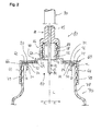
Fig. 1 ; - Fig. 3
- is a side view of the adaptor;
- Fig. 4
- is a cross-sectional view of the adaptor along line IV-IV in
Fig. 3 ; - Fig. 5
- is a perspective view of showing the adaptor substantially from the upper side;
- Fig. 6
- is a perspective view showing the adaptor substantially from the lower side;
- Fig. 7
- is a cross-sectional view similar to
Fig. 2 showing the adaptor according to a second embodiment; - Fig. 8
- is a cross-sectional view similar to
Fig. 2 showing the adaptor according to a third embodiment, and - Fig. 9
- is a cross-sectional view similar to
Fig. 2 showing the adaptor according to a fourth embodiment. -
Fig. 1 schematically shows a feedingcoupling 80 connected to a feedingcontainer 70 by means of anadaptor 10 according to the present invention. The feedingcontainer 70 is a baby bottle having anopening 72 at theupper side 74. The feedingcoupling 80 can be connected with a feeding conduit 90 (cf.Fig. 2 ) to feed a patient with a fluid contained in the feedingcontainer 70. In order to feed the patient, the feedingcontainer 70 is mounted such that it hangs downward. - As can be seen from
Fig. 2 to 6 theadaptor 10 comprises a supportingmember 20 for connection with the feedingcontainer 70, a sealing 30 which is fastened to the supportingmember 20 in an area of the supportingmember 20 suitable for providing a fluid-tight connection between theadaptor 10 and the feedingcontainer 70 and anend section 50 suitable for connecting theadaptor 10 to the feedingcoupling 80. Further, there is anintermediate section 40 between the supportingmember 20 and theend section 50. Theintermediate section 40 is made of the same rigid plastic material as the supportingmember 20 and theend section 50. Further, afastening element 60 shaped as a cap and having abase plate 62 and awall 64 for detachably fastening theadaptor 10 to the feedingcontainer 70 can be taken fromFig. 1 and2 . Thewall 64 is provided with a threadedsection 66 for engaging with a threadedsection 79 on a outside 78 of the feedingcontainer 70. Preferably, the supportingmember 20, the sealing 30, theintermediate section 40 and theend section 50 are shaped annular. - As
Fig. 2 shows, the supportingmember 20 comprises a supporting plate orring 22 which is applied on arim 76 at theupper side 74 of the feedingcontainer 70 around theopening 72. - Further, as can be taken from
Fig. 2 to 6 , the sealing 30 comprises an annular shaped sealingmember 31 having afirst end 32 which is fixed to the supportingplate 22 and asecond end 33 which is a free end extending into the interior of the feedingcontainer 70. The sealingmember 31 is moulded at least partially over or moulded to the supportingmember 20 in an area of the supportingplate 22 suitable for providing a fluid-tight connection between theadaptor 10 and the feedingcontainer 70. According toFigs. 2 to 4 , the sealingmember 31 extends substantially in a longitudinal direction L of theadaptor 10. "Substantially" means in the present embodiment that the sealingmember 31 extends in an inclined direction including an angle α between the extension of the sealingmember 31 and the extension of the supportingplate 22. Preferably this angle α is more than 90°, in particular between about 91° and about 135°. Thesecond end 33 is a tapered end. - In particular, the configuration of the inclined extension and/or the
tapered end 33 of the sealingmember 31 enables theadaptor 10 to cooperate with a range of different diameters for theopening 72 and/or with a range of different sizes of feedingcontainers 70. Moreover, the sealingmember 31 is shaped and/or fixed to theadaptor 10 in such a manner that theadaptor 10 can cooperate with different sizes of theopening 72 of the feedingcontainer 70. - The
intermediate section 40 comprises abase 42, in particular shaped as an annular plate, and awall 43 formed integrally with thebase 42 and made of the same material. Thewall 43 extends substantially parallel to the longitudinal direction L and thebase 42 extends in the radial direction R parallel to the supportingplate 22. This shape improves the stability of thewhole adaptor 10. - Further, a
thin layer 44, in particular a film or foil, is mounted to theadaptor 10 in the area of theintermediate section 40. Preferably, thethin layer 44 is bonded to thebase 42. Thisthin layer 44 seals the feedingcontainer 70 when theadaptor 10 is mounted to the feedingcontainer 70 and is secured by means of thefastening element 60. - The
end section 50 is shaped cylindrical and comprises afirst end 52, asecond end 54 and acentral bore 56. Also theend section 50 is formed integrally with the supportingmember 20 and theintermediate section 40 and from a rigid plastic material. Thesecond end 54 is formed as a free end. The wall of theend section 50 comprises a threadedsection 58 in order to connect the feedingcoupling 80 to theend section 50 and, thus, to theadaptor 10. - The feeding
coupling 80 comprises afirst end portion 86, a second end portion 88 and a threadedsection 89. Atube 82 extends along the longitudinal direction L throughfirst end portion 86 and/or second end portion 88 to provide a feeding channel 83 from the interior of the feedingcontainer 70 to an outlet end of thetube 82 and to thefeeding conduit 90 connected to the second end portion 88. In order to achieve the flow of the feeding fluid out from the feedingcontainer 70 to thefeeding conduit 90, thetube 82 has a length which is long enough that afirst end 84 of thetube 82 extends through thethin layer 44 into the interior of the feedingcontainer 70. Asecond end 85 of thetube 82 ends at the upper side of the second end portion 88. In order to connect the feedingcoupling 80 to theend section 50 thefirst end portion 86 comprises a threadedsection 89 to be engaged with the threadedsection 58. - To connect the feeding
coupling 80 with theadaptor 10 thefirst end 84 of thetube 82 is introduced into thebore 56. Then, thefirst end portion 86 is screwed with its threadedsection 89 on the threadedsection 58 of theend section 50. While screwing the feedingcoupling 80 onto theend section 50 the sharpfirst end 84 of thetube 82 pierces through thethin layer 44 and enters into the upper area of the feedingcontainer 70. Finally, the feedingconduit 90 can be connected to the free second end portion 88. -
Fig. 7 shows theadaptor 10 according to a second embodiment, wherein only the sealing 30 is different compared to the first embodiment ofFig. 2 . The sealing 30 comprises the sealingmember 31 corresponding toFig. 2 and in addition a sealingmember 34, which can also be designated as gasket. The sealingmember 34 is connected to alower side 24 of the supportingplate 22 and/or to the sealingmember 31. Further, the sealingmember 34 extends parallel to the supportingplate 22. Preferably, the sealingmember 34 is moulded onto thelower side 24. -
Fig. 8 shows theadaptor 10 according to a third embodiment, wherein only the sealing 30 is different compared to the first embodiment ofFig. 2 . The sealing 30 comprises only the sealingmember 34. The sealingmember 34 is connected to thelower side 24 of the supportingplate 22 and extends parallel to the supportingplate 22. Preferably, the sealingmember 34 is moulded onto thelower side 24. -
Fig. 9 shows theadaptor 10 according to a fourth embodiment, wherein only the sealing 30 is different compared to the first embodiment ofFig. 2 . The sealing 30 comprises only the sealingmember 34. The sealingmember 34 is connected to thelower side 24, theupper side 26 and/or to theface side 28 of the supportingplate 22 and extends parallel to the supportingplate 22. Preferably, the sealingmember 34 is moulded over thelower side 24, theupper side 26 and/or theface side 28 of the supportingplate 22. - In all embodiments of
Figures 2 ,7, 8 and 9 , the sealing 30 and the sealingmembers adaptor 10 for different sizes of feedingcontainers 70, in particular different sizes of theopening 72. -
- 10
- adaptor
- 20
- supporting member
- 22
- supporting plate
- 24
- lower side
- 26
- upper side
- 28
- face side
- 30
- sealing
- 31
- sealing member
- 32
- first end
- 33
- second end
- 34
- sealing member
- 40
- intermediate section
- 42
- base
- 43
- wall
- 44
- thin layer
- 50
- end section
- 52
- first end
- 54
- second end
- 56
- bore
- 58
- threaded section
- 60
- fastening element
- 62
- base plate
- 64
- wall
- 66
- threaded section
- 70
- feeding container
- 72
- opening
- 74
- upper side
- 76
- rim
- 78
- outside
- 79
- threaded section
- 80
- feeding coupling
- 82
- tube
- 83
- feeding channel
- 84
- first end
- 85
- second end
- 86
- first end portion
- 88
- second end portion
- 89
- threaded section
- 90
- feeding conduit
- L
- longitudinal direction
- R
- radial direction
- α
- angle
Claims (15)
- Adaptor (10) for connecting a feeding container (70) to an enteral feeding coupling (80), in particular for a baby bottle feeding assembly, characterised by
a supporting member (20) for connection with the feeding container (70),
a sealing (30) which is fastened to the supporting member (20) suitable for providing a fluid-tight connection between the adaptor (10) and the feeding container (70) and
an end section (50) suitable for connecting the adaptor (10) to the feeding coupling (80). - Adaptor (10) according to claim 1, characterised in that the sealing (30) comprises at least one sealing member (31, 34).
- Adaptor (10) according to claim 2, characterised in that the sealing member (31, 34) is integrally formed with the supporting member (20), in particular is moulded at least partially over or moulded to the supporting member (20).
- Adaptor (10) according to claim 2 or 3, characterised in that the sealing member (31, 34) extends substantially parallel to the supporting member (20) or in an inclined direction from the supporting member (20).
- Adaptor (10) according to any one of claims 2 to 4, characterised in that the sealing member (31, 34) is tapered and/or is shaped annular.
- Adaptor (10) according to any one of the preceding claims, characterised by an intermediate section (40) between the supporting member (20) and the end section (50).
- Adaptor (10) according to any one of the preceding claims, characterised by a thin layer (44), in particular a foil, which can be pierced through when the feeding coupling (80) is connected to the adaptor (10).
- Adaptor (10) according to any one of the preceding claims, characterised in that the thin layer (44) is connected to the intermediate section (40) and/or the supporting member (20).
- Adaptor (10) according to any one of the preceding claims, characterised by a fastening element (60) for detachably fastening the adaptor (10) to the feeding container (70), wherein the fastening element (60) is separate from the supporting member (20), in particular shaped as a cap, or integrally formed with the supporting member (20).
- Adaptor (10) according to claim 9, characterised in that the fastening element (70) comprises a threaded section (72) for engaging a threaded section (79) of the feeding container (70).
- Adaptor (10) according to any one of the preceding claims, characterised in that the end section (50) comprises a threaded section (58) for engaging a threaded section (89) of the feeding coupling (80).
- Adaptor (10) according to any one of the preceding claims, characterised in that the feeding coupling (80) comprises a tube (82) having a feeding channel (83) for a fluid connection between the feeding container (70) and the feeding conduit (90).
- Adaptor (10) according to any one of the preceding claims, characterised in that the feeding coupling (80) comprises a first end portion (88) for fastening the feeding coupling (80) to the end section (50) of the adaptor (10) and a second end portion (86) for connecting the feeding conduit (90) to the feeding coupling (80).
- Adaptor (10) according to any one of the preceding claims, characterised in that the feeding coupling (80) comprises a threaded section (89) for engaging the threaded section (58) of the end section (50).
- Adaptor (10) according to any one of the preceding claims, characterised in that the feeding container (70) is a baby bottle.
Priority Applications (1)
| Application Number | Priority Date | Filing Date | Title |
|---|---|---|---|
| EP20100008315 EP2417958B1 (en) | 2010-08-10 | 2010-08-10 | Adaptor for connecting a feeding container to an enteral feeding coupling, in particular for a baby bottle feeding assembly |
Applications Claiming Priority (1)
| Application Number | Priority Date | Filing Date | Title |
|---|---|---|---|
| EP20100008315 EP2417958B1 (en) | 2010-08-10 | 2010-08-10 | Adaptor for connecting a feeding container to an enteral feeding coupling, in particular for a baby bottle feeding assembly |
Publications (2)
| Publication Number | Publication Date |
|---|---|
| EP2417958A1 true EP2417958A1 (en) | 2012-02-15 |
| EP2417958B1 EP2417958B1 (en) | 2013-01-02 |
Family
ID=43416390
Family Applications (1)
| Application Number | Title | Priority Date | Filing Date |
|---|---|---|---|
| EP20100008315 Not-in-force EP2417958B1 (en) | 2010-08-10 | 2010-08-10 | Adaptor for connecting a feeding container to an enteral feeding coupling, in particular for a baby bottle feeding assembly |
Country Status (1)
| Country | Link |
|---|---|
| EP (1) | EP2417958B1 (en) |
Cited By (5)
| Publication number | Priority date | Publication date | Assignee | Title |
|---|---|---|---|---|
| US9925120B2 (en) | 2012-11-14 | 2018-03-27 | Abbott Laboratories | Cap suitable for use with enteral feeding container |
| CN112974027A (en) * | 2019-12-13 | 2021-06-18 | 苏州宝时得电动工具有限公司 | Sprayer with a spray tube |
| CN114010439A (en) * | 2021-12-13 | 2022-02-08 | 黑龙江省医院 | Gastroenterology nursing liquid food supply device |
| CN115427129A (en) * | 2020-04-28 | 2022-12-02 | 真水株式会社 | Water purifying filter with combined filling opening of beverage container |
| US20250332070A1 (en) * | 2024-04-25 | 2025-10-30 | Avent, Inc. | Enteral Feeding Bottle |
Citations (2)
| Publication number | Priority date | Publication date | Assignee | Title |
|---|---|---|---|---|
| US20030132185A1 (en) * | 2001-12-04 | 2003-07-17 | Beaudette Susan A. | Squeezable, fillable feeding device |
| US20040011760A1 (en) * | 2002-07-20 | 2004-01-22 | Marco Schupp | Bottle with special top for use in the medical field |
-
2010
- 2010-08-10 EP EP20100008315 patent/EP2417958B1/en not_active Not-in-force
Patent Citations (2)
| Publication number | Priority date | Publication date | Assignee | Title |
|---|---|---|---|---|
| US20030132185A1 (en) * | 2001-12-04 | 2003-07-17 | Beaudette Susan A. | Squeezable, fillable feeding device |
| US20040011760A1 (en) * | 2002-07-20 | 2004-01-22 | Marco Schupp | Bottle with special top for use in the medical field |
Cited By (8)
| Publication number | Priority date | Publication date | Assignee | Title |
|---|---|---|---|---|
| US9925120B2 (en) | 2012-11-14 | 2018-03-27 | Abbott Laboratories | Cap suitable for use with enteral feeding container |
| CN112974027A (en) * | 2019-12-13 | 2021-06-18 | 苏州宝时得电动工具有限公司 | Sprayer with a spray tube |
| CN112974027B (en) * | 2019-12-13 | 2025-08-19 | 苏州宝时得电动工具有限公司 | Sprayer |
| CN115427129A (en) * | 2020-04-28 | 2022-12-02 | 真水株式会社 | Water purifying filter with combined filling opening of beverage container |
| CN115427129B (en) * | 2020-04-28 | 2025-03-07 | 真水株式会社 | Beverage container inlet combined water purifier filter |
| CN114010439A (en) * | 2021-12-13 | 2022-02-08 | 黑龙江省医院 | Gastroenterology nursing liquid food supply device |
| CN114010439B (en) * | 2021-12-13 | 2022-10-14 | 黑龙江省医院 | Gastroenterology nursing liquid food feeding device |
| US20250332070A1 (en) * | 2024-04-25 | 2025-10-30 | Avent, Inc. | Enteral Feeding Bottle |
Also Published As
| Publication number | Publication date |
|---|---|
| EP2417958B1 (en) | 2013-01-02 |
Similar Documents
| Publication | Publication Date | Title |
|---|---|---|
| US20240374479A1 (en) | Adapter assembly for enteral feeding | |
| KR101668500B1 (en) | Spout and liquid containing body with spout | |
| US8689987B2 (en) | Container adapter | |
| CN101511322B (en) | Multi-purpose connector for enteral application | |
| US10688251B2 (en) | Self-righting tip cap | |
| EP3233176B1 (en) | System, apparatus and method employed with enteral systems | |
| CA2687667C (en) | Closure cap for a container for receiving liquids and in particular an enteral nutrient solution, and container having such a closure cap | |
| EP2417958B1 (en) | Adaptor for connecting a feeding container to an enteral feeding coupling, in particular for a baby bottle feeding assembly | |
| US6875204B1 (en) | Universal connector | |
| KR101699090B1 (en) | Spout and liquid containing body with spout | |
| JP2008149123A (en) | Enteral feeding set | |
| CN107106410B (en) | Connector system with at least two extraction ports | |
| MX2015006114A (en) | Cap suitable for use with enteral feeding container. | |
| CN209154515U (en) | Connector, the medical package object including the connector and the diaphragm for connector | |
| US20080302751A1 (en) | Baby bottle/beverage device | |
| US20090149804A1 (en) | Mother's Milk Container Closure and Attachment Assembly | |
| CN107580488A (en) | Container for medical fluid | |
| RU2850559C1 (en) | Universal nozzle for containers for liquid media | |
| JP2010047264A (en) | Spout for replaceable flexible package | |
| US20240390233A1 (en) | Bolus Feed Delivery System | |
| WO2014043765A1 (en) | Adaptor for dispenser assembly | |
| HK1243312B (en) | Connector system comprising at least two withdrawal ports | |
| HK1243313B (en) | Connector system comprising at least two outlet ports |
Legal Events
| Date | Code | Title | Description |
|---|---|---|---|
| AK | Designated contracting states |
Kind code of ref document: A1 Designated state(s): AL AT BE BG CH CY CZ DE DK EE ES FI FR GB GR HR HU IE IS IT LI LT LU LV MC MK MT NL NO PL PT RO SE SI SK SM TR |
|
| AX | Request for extension of the european patent |
Extension state: BA ME RS |
|
| PUAI | Public reference made under article 153(3) epc to a published international application that has entered the european phase |
Free format text: ORIGINAL CODE: 0009012 |
|
| 17P | Request for examination filed |
Effective date: 20120302 |
|
| 17Q | First examination report despatched |
Effective date: 20120509 |
|
| GRAP | Despatch of communication of intention to grant a patent |
Free format text: ORIGINAL CODE: EPIDOSNIGR1 |
|
| GRAS | Grant fee paid |
Free format text: ORIGINAL CODE: EPIDOSNIGR3 |
|
| GRAA | (expected) grant |
Free format text: ORIGINAL CODE: 0009210 |
|
| AK | Designated contracting states |
Kind code of ref document: B1 Designated state(s): AL AT BE BG CH CY CZ DE DK EE ES FI FR GB GR HR HU IE IS IT LI LT LU LV MC MK MT NL NO PL PT RO SE SI SK SM TR |
|
| REG | Reference to a national code |
Ref country code: GB Ref legal event code: FG4D |
|
| REG | Reference to a national code |
Ref country code: AT Ref legal event code: REF Ref document number: 591161 Country of ref document: AT Kind code of ref document: T Effective date: 20130115 Ref country code: CH Ref legal event code: EP |
|
| REG | Reference to a national code |
Ref country code: IE Ref legal event code: FG4D |
|
| REG | Reference to a national code |
Ref country code: DE Ref legal event code: R096 Ref document number: 602010004358 Country of ref document: DE Effective date: 20130228 |
|
| REG | Reference to a national code |
Ref country code: AT Ref legal event code: MK05 Ref document number: 591161 Country of ref document: AT Kind code of ref document: T Effective date: 20130102 |
|
| REG | Reference to a national code |
Ref country code: NL Ref legal event code: VDEP Effective date: 20130102 |
|
| PG25 | Lapsed in a contracting state [announced via postgrant information from national office to epo] |
Ref country code: SI Free format text: LAPSE BECAUSE OF FAILURE TO SUBMIT A TRANSLATION OF THE DESCRIPTION OR TO PAY THE FEE WITHIN THE PRESCRIBED TIME-LIMIT Effective date: 20130102 |
|
| REG | Reference to a national code |
Ref country code: LT Ref legal event code: MG4D |
|
| PG25 | Lapsed in a contracting state [announced via postgrant information from national office to epo] |
Ref country code: AT Free format text: LAPSE BECAUSE OF FAILURE TO SUBMIT A TRANSLATION OF THE DESCRIPTION OR TO PAY THE FEE WITHIN THE PRESCRIBED TIME-LIMIT Effective date: 20130102 Ref country code: IS Free format text: LAPSE BECAUSE OF FAILURE TO SUBMIT A TRANSLATION OF THE DESCRIPTION OR TO PAY THE FEE WITHIN THE PRESCRIBED TIME-LIMIT Effective date: 20130502 Ref country code: CZ Free format text: LAPSE BECAUSE OF FAILURE TO SUBMIT A TRANSLATION OF THE DESCRIPTION OR TO PAY THE FEE WITHIN THE PRESCRIBED TIME-LIMIT Effective date: 20130102 Ref country code: NO Free format text: LAPSE BECAUSE OF FAILURE TO SUBMIT A TRANSLATION OF THE DESCRIPTION OR TO PAY THE FEE WITHIN THE PRESCRIBED TIME-LIMIT Effective date: 20130402 Ref country code: ES Free format text: LAPSE BECAUSE OF FAILURE TO SUBMIT A TRANSLATION OF THE DESCRIPTION OR TO PAY THE FEE WITHIN THE PRESCRIBED TIME-LIMIT Effective date: 20130413 Ref country code: SE Free format text: LAPSE BECAUSE OF FAILURE TO SUBMIT A TRANSLATION OF THE DESCRIPTION OR TO PAY THE FEE WITHIN THE PRESCRIBED TIME-LIMIT Effective date: 20130102 Ref country code: LT Free format text: LAPSE BECAUSE OF FAILURE TO SUBMIT A TRANSLATION OF THE DESCRIPTION OR TO PAY THE FEE WITHIN THE PRESCRIBED TIME-LIMIT Effective date: 20130102 Ref country code: BG Free format text: LAPSE BECAUSE OF FAILURE TO SUBMIT A TRANSLATION OF THE DESCRIPTION OR TO PAY THE FEE WITHIN THE PRESCRIBED TIME-LIMIT Effective date: 20130402 Ref country code: BE Free format text: LAPSE BECAUSE OF FAILURE TO SUBMIT A TRANSLATION OF THE DESCRIPTION OR TO PAY THE FEE WITHIN THE PRESCRIBED TIME-LIMIT Effective date: 20130102 |
|
| PG25 | Lapsed in a contracting state [announced via postgrant information from national office to epo] |
Ref country code: PT Free format text: LAPSE BECAUSE OF FAILURE TO SUBMIT A TRANSLATION OF THE DESCRIPTION OR TO PAY THE FEE WITHIN THE PRESCRIBED TIME-LIMIT Effective date: 20130502 Ref country code: PL Free format text: LAPSE BECAUSE OF FAILURE TO SUBMIT A TRANSLATION OF THE DESCRIPTION OR TO PAY THE FEE WITHIN THE PRESCRIBED TIME-LIMIT Effective date: 20130102 Ref country code: LV Free format text: LAPSE BECAUSE OF FAILURE TO SUBMIT A TRANSLATION OF THE DESCRIPTION OR TO PAY THE FEE WITHIN THE PRESCRIBED TIME-LIMIT Effective date: 20130102 Ref country code: NL Free format text: LAPSE BECAUSE OF FAILURE TO SUBMIT A TRANSLATION OF THE DESCRIPTION OR TO PAY THE FEE WITHIN THE PRESCRIBED TIME-LIMIT Effective date: 20130102 Ref country code: GR Free format text: LAPSE BECAUSE OF FAILURE TO SUBMIT A TRANSLATION OF THE DESCRIPTION OR TO PAY THE FEE WITHIN THE PRESCRIBED TIME-LIMIT Effective date: 20130403 Ref country code: FI Free format text: LAPSE BECAUSE OF FAILURE TO SUBMIT A TRANSLATION OF THE DESCRIPTION OR TO PAY THE FEE WITHIN THE PRESCRIBED TIME-LIMIT Effective date: 20130102 |
|
| PG25 | Lapsed in a contracting state [announced via postgrant information from national office to epo] |
Ref country code: HR Free format text: LAPSE BECAUSE OF FAILURE TO SUBMIT A TRANSLATION OF THE DESCRIPTION OR TO PAY THE FEE WITHIN THE PRESCRIBED TIME-LIMIT Effective date: 20130102 |
|
| PG25 | Lapsed in a contracting state [announced via postgrant information from national office to epo] |
Ref country code: RO Free format text: LAPSE BECAUSE OF FAILURE TO SUBMIT A TRANSLATION OF THE DESCRIPTION OR TO PAY THE FEE WITHIN THE PRESCRIBED TIME-LIMIT Effective date: 20130102 Ref country code: EE Free format text: LAPSE BECAUSE OF FAILURE TO SUBMIT A TRANSLATION OF THE DESCRIPTION OR TO PAY THE FEE WITHIN THE PRESCRIBED TIME-LIMIT Effective date: 20130102 Ref country code: DK Free format text: LAPSE BECAUSE OF FAILURE TO SUBMIT A TRANSLATION OF THE DESCRIPTION OR TO PAY THE FEE WITHIN THE PRESCRIBED TIME-LIMIT Effective date: 20130102 Ref country code: SK Free format text: LAPSE BECAUSE OF FAILURE TO SUBMIT A TRANSLATION OF THE DESCRIPTION OR TO PAY THE FEE WITHIN THE PRESCRIBED TIME-LIMIT Effective date: 20130102 |
|
| PLBE | No opposition filed within time limit |
Free format text: ORIGINAL CODE: 0009261 |
|
| STAA | Information on the status of an ep patent application or granted ep patent |
Free format text: STATUS: NO OPPOSITION FILED WITHIN TIME LIMIT |
|
| PG25 | Lapsed in a contracting state [announced via postgrant information from national office to epo] |
Ref country code: CY Free format text: LAPSE BECAUSE OF FAILURE TO SUBMIT A TRANSLATION OF THE DESCRIPTION OR TO PAY THE FEE WITHIN THE PRESCRIBED TIME-LIMIT Effective date: 20130102 |
|
| 26N | No opposition filed |
Effective date: 20131003 |
|
| PG25 | Lapsed in a contracting state [announced via postgrant information from national office to epo] |
Ref country code: IT Free format text: LAPSE BECAUSE OF FAILURE TO SUBMIT A TRANSLATION OF THE DESCRIPTION OR TO PAY THE FEE WITHIN THE PRESCRIBED TIME-LIMIT Effective date: 20130102 |
|
| REG | Reference to a national code |
Ref country code: DE Ref legal event code: R097 Ref document number: 602010004358 Country of ref document: DE Effective date: 20131003 |
|
| PG25 | Lapsed in a contracting state [announced via postgrant information from national office to epo] |
Ref country code: MC Free format text: LAPSE BECAUSE OF FAILURE TO SUBMIT A TRANSLATION OF THE DESCRIPTION OR TO PAY THE FEE WITHIN THE PRESCRIBED TIME-LIMIT Effective date: 20130102 |
|
| REG | Reference to a national code |
Ref country code: IE Ref legal event code: MM4A |
|
| PG25 | Lapsed in a contracting state [announced via postgrant information from national office to epo] |
Ref country code: IE Free format text: LAPSE BECAUSE OF NON-PAYMENT OF DUE FEES Effective date: 20130810 |
|
| REG | Reference to a national code |
Ref country code: CH Ref legal event code: PL |
|
| PG25 | Lapsed in a contracting state [announced via postgrant information from national office to epo] |
Ref country code: LI Free format text: LAPSE BECAUSE OF NON-PAYMENT OF DUE FEES Effective date: 20140831 Ref country code: CH Free format text: LAPSE BECAUSE OF NON-PAYMENT OF DUE FEES Effective date: 20140831 |
|
| PG25 | Lapsed in a contracting state [announced via postgrant information from national office to epo] |
Ref country code: SM Free format text: LAPSE BECAUSE OF FAILURE TO SUBMIT A TRANSLATION OF THE DESCRIPTION OR TO PAY THE FEE WITHIN THE PRESCRIBED TIME-LIMIT Effective date: 20130102 |
|
| PG25 | Lapsed in a contracting state [announced via postgrant information from national office to epo] |
Ref country code: TR Free format text: LAPSE BECAUSE OF FAILURE TO SUBMIT A TRANSLATION OF THE DESCRIPTION OR TO PAY THE FEE WITHIN THE PRESCRIBED TIME-LIMIT Effective date: 20130102 Ref country code: MT Free format text: LAPSE BECAUSE OF FAILURE TO SUBMIT A TRANSLATION OF THE DESCRIPTION OR TO PAY THE FEE WITHIN THE PRESCRIBED TIME-LIMIT Effective date: 20130102 |
|
| PG25 | Lapsed in a contracting state [announced via postgrant information from national office to epo] |
Ref country code: MK Free format text: LAPSE BECAUSE OF FAILURE TO SUBMIT A TRANSLATION OF THE DESCRIPTION OR TO PAY THE FEE WITHIN THE PRESCRIBED TIME-LIMIT Effective date: 20130102 Ref country code: HU Free format text: LAPSE BECAUSE OF FAILURE TO SUBMIT A TRANSLATION OF THE DESCRIPTION OR TO PAY THE FEE WITHIN THE PRESCRIBED TIME-LIMIT; INVALID AB INITIO Effective date: 20100810 Ref country code: LU Free format text: LAPSE BECAUSE OF NON-PAYMENT OF DUE FEES Effective date: 20130810 |
|
| REG | Reference to a national code |
Ref country code: FR Ref legal event code: PLFP Year of fee payment: 7 |
|
| REG | Reference to a national code |
Ref country code: FR Ref legal event code: PLFP Year of fee payment: 8 |
|
| PGFP | Annual fee paid to national office [announced via postgrant information from national office to epo] |
Ref country code: FR Payment date: 20170720 Year of fee payment: 8 Ref country code: DE Payment date: 20170719 Year of fee payment: 8 Ref country code: GB Payment date: 20170719 Year of fee payment: 8 |
|
| PG25 | Lapsed in a contracting state [announced via postgrant information from national office to epo] |
Ref country code: AL Free format text: LAPSE BECAUSE OF FAILURE TO SUBMIT A TRANSLATION OF THE DESCRIPTION OR TO PAY THE FEE WITHIN THE PRESCRIBED TIME-LIMIT Effective date: 20130102 |
|
| REG | Reference to a national code |
Ref country code: DE Ref legal event code: R119 Ref document number: 602010004358 Country of ref document: DE |
|
| GBPC | Gb: european patent ceased through non-payment of renewal fee |
Effective date: 20180810 |
|
| PG25 | Lapsed in a contracting state [announced via postgrant information from national office to epo] |
Ref country code: DE Free format text: LAPSE BECAUSE OF NON-PAYMENT OF DUE FEES Effective date: 20190301 |
|
| PG25 | Lapsed in a contracting state [announced via postgrant information from national office to epo] |
Ref country code: FR Free format text: LAPSE BECAUSE OF NON-PAYMENT OF DUE FEES Effective date: 20180831 |
|
| PG25 | Lapsed in a contracting state [announced via postgrant information from national office to epo] |
Ref country code: GB Free format text: LAPSE BECAUSE OF NON-PAYMENT OF DUE FEES Effective date: 20180810 |