EP2417658B1 - Thermal battery electrolyte compositions, electrode-electrolyte composites, and batteries including the same - Google Patents
Thermal battery electrolyte compositions, electrode-electrolyte composites, and batteries including the same Download PDFInfo
- Publication number
- EP2417658B1 EP2417658B1 EP10712866.2A EP10712866A EP2417658B1 EP 2417658 B1 EP2417658 B1 EP 2417658B1 EP 10712866 A EP10712866 A EP 10712866A EP 2417658 B1 EP2417658 B1 EP 2417658B1
- Authority
- EP
- European Patent Office
- Prior art keywords
- electrolyte
- lithium
- battery
- electrolyte material
- cathode
- Prior art date
- Legal status (The legal status is an assumption and is not a legal conclusion. Google has not performed a legal analysis and makes no representation as to the accuracy of the status listed.)
- Active
Links
Images


Classifications
-
- H—ELECTRICITY
- H01—ELECTRIC ELEMENTS
- H01M—PROCESSES OR MEANS, e.g. BATTERIES, FOR THE DIRECT CONVERSION OF CHEMICAL ENERGY INTO ELECTRICAL ENERGY
- H01M6/00—Primary cells; Manufacture thereof
- H01M6/30—Deferred-action cells
- H01M6/36—Deferred-action cells containing electrolyte and made operational by physical means, e.g. thermal cells
-
- H—ELECTRICITY
- H01—ELECTRIC ELEMENTS
- H01M—PROCESSES OR MEANS, e.g. BATTERIES, FOR THE DIRECT CONVERSION OF CHEMICAL ENERGY INTO ELECTRICAL ENERGY
- H01M4/00—Electrodes
- H01M4/02—Electrodes composed of, or comprising, active material
- H01M4/36—Selection of substances as active materials, active masses, active liquids
- H01M4/38—Selection of substances as active materials, active masses, active liquids of elements or alloys
- H01M4/381—Alkaline or alkaline earth metals elements
- H01M4/382—Lithium
-
- H—ELECTRICITY
- H01—ELECTRIC ELEMENTS
- H01M—PROCESSES OR MEANS, e.g. BATTERIES, FOR THE DIRECT CONVERSION OF CHEMICAL ENERGY INTO ELECTRICAL ENERGY
- H01M4/00—Electrodes
- H01M4/02—Electrodes composed of, or comprising, active material
- H01M4/36—Selection of substances as active materials, active masses, active liquids
- H01M4/58—Selection of substances as active materials, active masses, active liquids of inorganic compounds other than oxides or hydroxides, e.g. sulfides, selenides, tellurides, halogenides or LiCoFy; of polyanionic structures, e.g. phosphates, silicates or borates
- H01M4/581—Chalcogenides or intercalation compounds thereof
- H01M4/5815—Sulfides
-
- H—ELECTRICITY
- H01—ELECTRIC ELEMENTS
- H01M—PROCESSES OR MEANS, e.g. BATTERIES, FOR THE DIRECT CONVERSION OF CHEMICAL ENERGY INTO ELECTRICAL ENERGY
- H01M6/00—Primary cells; Manufacture thereof
- H01M6/14—Cells with non-aqueous electrolyte
- H01M6/18—Cells with non-aqueous electrolyte with solid electrolyte
- H01M6/182—Cells with non-aqueous electrolyte with solid electrolyte with halogenide as solid electrolyte
- H01M6/183—Cells with non-aqueous electrolyte with solid electrolyte with halogenide as solid electrolyte with fluoride as solid electrolyte
-
- H—ELECTRICITY
- H01—ELECTRIC ELEMENTS
- H01M—PROCESSES OR MEANS, e.g. BATTERIES, FOR THE DIRECT CONVERSION OF CHEMICAL ENERGY INTO ELECTRICAL ENERGY
- H01M6/00—Primary cells; Manufacture thereof
- H01M6/14—Cells with non-aqueous electrolyte
- H01M6/18—Cells with non-aqueous electrolyte with solid electrolyte
- H01M6/20—Cells with non-aqueous electrolyte with solid electrolyte working at high temperature
-
- H—ELECTRICITY
- H01—ELECTRIC ELEMENTS
- H01M—PROCESSES OR MEANS, e.g. BATTERIES, FOR THE DIRECT CONVERSION OF CHEMICAL ENERGY INTO ELECTRICAL ENERGY
- H01M2300/00—Electrolytes
- H01M2300/0017—Non-aqueous electrolytes
- H01M2300/0065—Solid electrolytes
- H01M2300/0068—Solid electrolytes inorganic
- H01M2300/008—Halides
-
- H—ELECTRICITY
- H01—ELECTRIC ELEMENTS
- H01M—PROCESSES OR MEANS, e.g. BATTERIES, FOR THE DIRECT CONVERSION OF CHEMICAL ENERGY INTO ELECTRICAL ENERGY
- H01M4/00—Electrodes
- H01M4/02—Electrodes composed of, or comprising, active material
- H01M4/36—Selection of substances as active materials, active masses, active liquids
- H01M4/38—Selection of substances as active materials, active masses, active liquids of elements or alloys
- H01M4/40—Alloys based on alkali metals
- H01M4/405—Alloys based on lithium
Definitions
- the field of this disclosure generally relates to electrolyte material for use in thermal batteries and, particularly, to ternary or quaternary electrolyte material that is substantially binder-free.
- the disclosure also relates to composites of electrodes and electrolytes that contain the electrolyte material and cathode and/or anode material and to batteries that contain the electrolyte material.
- Thermal batteries tend to have relatively long shelf lives, high energy densities, require relatively low maintenance, and can withstand relatively high temperatures. Thermal batteries also tend to provide a short burst of power over a relatively short period of time. The burst may range from less than a second to an hour or more, with power typically ranging from about a watt or less to kilowatts. Such properties make thermal batteries suitable for military (e.g., batteries for missile guidance systems) and space exploration applications. Thermal batteries may also be used in other applications, such as in electric vehicles.
- a typical thermal battery includes an anode, a cathode, an electrolyte-separator containing a solid electrolyte that is non-conductive at ambient temperature, and a pyrotechnic material (e.g., heat pellet as in Figure 1 which may contain, for example, Fe-KClO 4 powder) that provides a heat source to the battery.
- a pyrotechnic material e.g., heat pellet as in Figure 1 which may contain, for example, Fe-KClO 4 powder
- an external stimulus is applied to the battery.
- an electrical current may be applied to the battery to set off an electric match or an electro-active squib or a mechanical force (e.g., mechanical shock) may be applied to set off a concussion primer.
- the external stimulus causes the pyrotechnic material to ignite and begin to heat. Heat produced from the pyrotechnic material causes the previously solid electrolyte to melt and become conductive, which allows the battery to provide power for a desired application.
- the anodes of thermal batteries are generally formed of an alkali or alkaline earth metal or alloy.
- a typical anode includes lithium metal or a lithium alloy, such as lithium aluminum, lithium silicon, or lithium boron.
- Electrolytes for use with thermal batteries often include a eutectic mixture (i.e., a mixture which melts at a temperature lower than each of the individual components) of lithium chloride and potassium chloride and a binder, such as MgO, fumed silica or kaolin), which assists in containing the electrolyte within the thermal battery assembly upon melting, such as by capillary action, surface tension, or both.
- a binder such as MgO, fumed silica or kaolin
- the electrolyte material may disperse throughout the battery, causing undesired shunts or short circuits in the cell.
- the binder materials tend to be relatively resistant to ionic conduction and thus inclusion of the binder increases the impedance of the battery.
- Cathode material for thermal batteries may vary in accordance with a variety of design parameters and generally includes a metal oxide or metal sulfide.
- a metal oxide or metal sulfide By way of example, iron oxide (FeO 4 ), iron disulfide (FeS 2 ) or cobalt (CoS 2 ) disulfide are often used as cathode material.
- Thermal batteries are often formed using pellet techniques, such that each of the electrolyte, cathode, and heat source are formed into a wafer.
- the respective cell component chemicals are processed into powders and the powders are pressed together to form the cell.
- Each component may be formed as a discrete part, or the anode and/or cathode may include (i.e., be flooded with) electrolyte material to improve the conductivity of the cell.
- US 5534367 describes an electrolyte, for use in a battery, comprising a eutectic mixture of lithium chloride, lithium bromide, potassium bromide and lithium fluoride. However, the respective amounts differ to those according to the present invention.
- US 2008/299447 describes a molten salt electrolyte, for a battery, the electrolyte comprising lithium chloride, lithium bromide, potassium bromide and lithium fluoride. Lithium fluoride is present in relatively low amounts.
- the electrolyte contains lithium chloride and lithium bromide and lithium fluoride.
- US-H-1335 H (US Statutory Invention Registration) describes an electrochemical cell having an electrolyte composed of lithium chloride, lithium fluoride and lithium bromide.
- JP 02 061962 describes an electrolyte formed by mixing magnesium oxide with lithium fluoride, lithium chloride and lithium bromide.
- the present disclosure provides improved electrolyte material for use in thermal batteries including the cathodes and anodes thereof.
- the ways in which the improved electrolyte, cathode, anode, and battery overcome the shortcomings of the prior art are discussed in more detail below.
- the disclosure provides a substantially binder-free thermal battery electrolyte, and a battery and components thereof, including the substantially binder-free electrolyte material.
- One aspect of the present disclosure is directed to an electrolyte material for use in thermal batteries, the electrolyte material being substantially binder-free.
- the material includes at least 25 wt% lithium bromide, at least 4 wt% lithium chloride, and at least 42 wt% lithium fluoride, and at least 1 wt% potassium bromide and no more than 12 wt% potassium bromide.
- a composite electrode-electrolyte for use in a thermal battery includes an electrode and substantially binder-free electrolyte material.
- the electrode may contain cathode material or anode material.
- the electrolyte material includes at least 25 wt% lithium bromide, at least 4 wt% lithium chloride, at least 42 wt% lithium fluoride, and at least 1 wt% potassium bromide and no more than 12 wt% potassium bromide.
- a battery in a further aspect, includes an anode material, cathode material and electrolyte material.
- the electrolyte material is substantially binder-free and includes at least 25 wt% lithium bromide, at least 4 wt% lithium chloride, at least 42 wt% lithium fluoride, and at least 1 wt% potassium bromide and no more than 12 wt% potassium bromide.
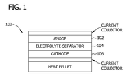
- FIG. 1 illustrates a thermal battery 100, in accordance with various embodiments of the disclosure, which includes an anode 102, an electrolyte-separator (electrolyte) 104, and a cathode 106.
- the electrolyte material of the present disclosure is suitable as a constituent in any or all of these battery components.
- an “electrochemical device” may otherwise be referred to herein as a battery (and in some embodiments, a “thermal battery”), a capacitor, a cell, an electrochemical cell, or the like. It should be understood that these references are not limiting, and any device that involves electron transfer between an electrode and an electrolyte is contemplated within the scope of the present disclosure. Further, an electrochemical device may refer to single or multiple connected electrochemical devices, electrochemical cells, batteries or capacitors capable of supplying energy to a load, and none of the references herein to any particular device should be considered to limit the disclosure in any way.
- thermal battery 100 components are prepared by consolidating powders via a mechanical pressing operation to produce pellets (i.e., wafers).
- Thermal batteries using pressed components are prepared by assembling in stacks the various components such as the anode 102, electrolyte-separator 104, and cathode 106, plus a heat source pellet if applicable to the particular battery design. Assembly of one each of anode 102, electrolyte-separator 104, and cathode 106 comprises a single electrochemical cell. Multiple cells may be stacked in series to produce a thermal battery.
- thermal battery designs other than as shown in Figure 1 may be used without departing from the scope of the present disclosure.
- Thermal battery anode materials in accordance with various embodiments of the disclosure include any suitable alkaline earth metal or alkali metal.
- the anode includes lithium or lithium alloys, such as lithium aluminum, lithium silicon, and lithium boron alloys.
- the alloy is typically a powdered form.
- the anode may be "flooded" to form an anode-electrolyte composite wherein electrolyte salt is mixed with the lithium alloy powder and is part of the anode pellet that is pressed. The flooding allows ions to flow not just from the inner edge of the anode but from the bulk of the anode pellet.
- Cathode materials can be prepared in the same or similar manner as anode materials, such that powders are mixed and pressed.
- the cathode includes a metal compound, such as a metal oxide (e.g., FeO 4 ) or metal sulfide (e.g., FeS 2 , CoS 2 or mixtures thereof) as the active material in the cathode.
- Suitable cathode materials may also include an amount of a bimetal sulfide compound such as, for example, CuFeS 2 .
- cathode sulfide powders may be mixed with an electrolyte salt to provide a flooded cathode to improve battery performance.
- inclusion of the electrolyte, in accordance with exemplary embodiments of the disclosure, into the cathode pellets of a thermal battery so as to form a cathode-electrolyte composite improves the performance of a single cell containing a stack of anode pellet, electrolyte separator pellet and cathode pellet. The performance improvement is evident in the reduced cell impedance of the stack compared to a cathode using a conventional electrolyte.
- electrolyte material that does not include a binder (or is substantially binder-free) is used as the electrolyte-separator, is included in the anode material, and/or is included in the cathode material so as to form an electrode-electrolyte composite.
- the substantially binder-free electrolyte material may be incorporated into one or more battery components and alternative electrolyte material may be included in one or more of the other battery components.
- a "binder-less" electrolyte material generally refers to an electrolyte that contains essentially no conventional binder, such as, for example, MgO, fumed silica or clay minerals such as kaolinite (including kaolin clays which are known to be rich in kaolinite).
- the electrolyte material may contain less than about 5 wt% binder, less than about 3 wt%, less than about 1 wt%, less than about 0.1 wt% or even no amount of binder (based on the total weight of the electrolyte material).
- the sum of the concentrations of the electrolyte material components may be at least about 95 wt%, at least about 96 wt%, at least about 97 wt%, at least about 98 wt%, at least about 99 wt% or even about 100 wt% (based on the total weight of the electrolyte material).
- the electrolyte material components e.g., lithium bromide, lithium chloride, lithium fluoride, and potassium bromide
- the sum of the concentrations of the electrolyte material components may be at least about 95 wt%, at least about 96 wt%, at least about 97 wt%, at least about 98 wt%, at least about 99 wt% or even about 100 wt% (based on the total weight of the electrolyte material).
- the electrolyte material may consist of the recited components (the electrolyte material being, for example, a quaternary mixture of essentially four components) or consist essentially of these components (i.e., the material does not contain materials that are generally electrically conductive other than the recited components).
- conventional electrolyte salts in thermal batteries include a binder material to serve as a static support after activation. While the salt is an inert solid at low temperatures, activation of the battery either through external heating or by inclusion of heat-generating material (for example, Fe-KClO 4 powder) raises the temperature such that the electrolyte melts and ionic conduction is possible between the anode and cathode.
- Conventional molten salts includes a binder material (e.g., MgO, fumed silica or kaolin) to ensure continued separation of the anode and cathode, without which the cell or battery would experience a short circuit and cease to function upon activation.
- the chemistry of the present electrolyte is such that, after activation, the flowability of the molten salt is less than that of other salts used in thermal batteries, allowing the amount of binder to be minimized and even substantially eliminated.
- Lithium fluoride is characterized by a relatively higher melting temperature as compared to other electrolyte salts which allows portions of the lithium fluoride to remain in solid form.
- exemplary electrolyte compositions include a salt mixture of lithium bromide (LiBr), lithium chloride (LiCl), lithium fluoride (LiF) and, potassium bromide (KBr).
- the ratio of the four salts may vary, with preferred embodiments being in the ranges shown below.
- Table 3 Exemplary compositions for electrolyte materials Component Exemplary Wt% Exemplary Wt% Exemplary Wt% Exemplary Wt% Exemplary Wt% Exemplary Wt% Exemplary Wt% KBr 0-12 1-9 1-3 9-12 LiBr 25-41 25-41 30-38 32-39 LiCl 4-14 4-14 9-12 5-7 LiF 42-64 42-64 50-60 42-53
- the electrolyte material may contain, in various exemplary embodiments: at least about 25 wt% lithium bromide, at least about 30 wt%, at least about 35 wt%, or even at least about 40 wt% lithium bromide; at least about 4 wt% lithium chloride, at least about 6 wt%, at least about 8 wt%, at least about 10 wt%, or even at least about 12 wt% lithium chloride; at least about 42 wt% lithium fluoride, at least about 45 wt%, at least about 50 wt%, at least about 55 wt%, or even at least about 60 wt% lithium fluoride; and at least about 1 wt% potassium bromide, at least about 2 wt%, at least about 4 wt%, at least about 8 wt%, or even at least about 10 wt% potassium bromide.
- the electrolyte material may contain: no more than about 41 wt% lithium bromide; no more than about 14 wt% lithium chloride; no more than about 64 wt% lithium fluoride.
- the electrolyte material contains no more than about 12 wt% potassium bromide.
- the concentration of a recited component may be within a range bounded by any combination or permutation of the higher and lower concentration limits noted herein (e.g., between about 25 wt% and about 41 wt%, or between about 30 wt% and about 41 wt% lithium bromide), without departing from the intended scope of the present disclosure.
- electrolyte material may be formed by measuring a desired amount of each salt in the composition, physically mixing the salts, fusing the mixed material at high temperature (e.g., about 500°C ⁇ about 50°C), grinding the fused electrolyte, and passing the ground product through a sieve.
- high temperature e.g., about 500°C ⁇ about 50°C
- the size of the particles of the electrolyte material is not critical; however, the particle size should be consistent with typical battery manufacturing operations as dependent on the battery design as appreciated by those of skill in the art. For example, tape casting methods generally use smaller particles than pellet pressing methods.
- the electrolyte particles When pellet pressing methods are used to form the electrolyte material (such as when the electrolyte material is used to flood a cathode or anode), the electrolyte particles should be screened such that they are sufficiently small to allow proper filling of the die but yet large enough such that they do not infiltrate the gap between the punch and the die. In tape casting methods, the particles should be sufficiently small to allow casting of a thin tape. Suitable particle size ranges may be readily determined by those of skill in the art.
- the starting salt materials may be either in powder or granulated form and are preferably dried at a temperature sufficient to remove an amount of absorbed moisture (if any). Moisture may be removed as much as economically practical and as much as practical in view of the selected manufacturing process. Generally, the amount of moisture should be reduced to a level that does not cause unacceptable amounts of anode material oxidation.
- the electrolyte salt material may be heated, for example to a temperature of from about 100°C to about 400°C, to remove moisture from the material.
- Physical mixing may proceed via any mechanical mixing method, for example, stirring the salts by hand, agitating the ingredients in a Turbula blender, rolling the container on a jar mill, or the like. Mixing may proceed from 15 minutes to about 2 hours, depending on the total amount of salt and the manner of mixing.
- the mixed powder may be removed from the mixing container and placed into a crucible suitable for fusing the salts at high temperature.
- crucibles may be formed of refractory material that is able to withstand the high temperatures required to fuse the salts and be resistant to the corrosive effects of the molten salts.
- Salts are fused at a temperature sufficient to melt the bulk of the material such as, for example, at least about 500°C or even at least about 650°C. In accordance with various aspects of these embodiments, depending on the ratio of salts, only a portion of the mixture might fully melt during the fusing process.
- the resulting fused salt is ground. Grinding may take place either by hand using a mortar-pestle for small amounts, or using a large grinder such as a quaker mill for large amounts. After grinding, the ground fused salt is passed through a screen to remove any large particles that were missed in the grinding step. The large particles may be ground a second time to reduce their size to pass through the screen. Mesh size of the screen is variable according to the preferences of the user and the intended application.
- the resulting powder after mixing, fusing, grinding and sieving, may then be pressed into pellets (i.e., wafers) for use as electrolyte-separator or mixed into cathode powders and/or anode powders to form an electrode-electrolyte composite and serve as the flooding electrolyte in those components.
- the pellets may be formed by a hydraulic press in which the powder material is introduced into a pellet die and leveled (either mechanically or by hand). A hydraulic punch is lowered and compresses the powder into a pellet (i.e., wafer).
- Pelletting pressures are not critical; however, it is preferred to use pressures near the the highest capable pressures in the pelleting equipment within the mechanical limits of the equipment (e.g., the punch and die materials).
- compositions, methods and various parameters reflected therein are intended only to exemplify various aspects and embodiments of the disclosure, and are not intended to limit the scope of the claimed disclosure.
- FIG. 1 shows a stack arrangement of a thermal battery, including heat pellet 108 that would be used to melt the electrolyte upon battery activation. This arrangement, without heat pellet 108, was used for the single cell tests discussed in the Examples.
- Reference Example 1 Voltage Trace for a Cell having an Electrolyte-Separator Composed of Substantially Binder-free Ternary Electrolyte Material
- Fig. 2 illustrates a voltage trace from a single electrochemical cell including an electrolyte material, in accordance with embodiments of the disclosure, as the electrolyte-separator pellet.
- the composition of the electrolyte-separator of this cell was about 34 wt% LiBr, about 11 wt% LiCl, about 55 wt% LiF, and 0 wt% KBr.
- the cathode of the cell was an FeS 2 pellet flooded with a conventional KC1-LiCl eutectic electrolyte.
- the anode was a lithium-silicon alloy powder flooded with a conventional KCl-LiCl eutectic electrolyte.
- the cell stack was heated to a temperature of 500°C under compression to hold the pellets in contact with one another.
- a current draw of 1 ampere base load was applied with pulses of 5 amperes for 1 second duration applied every 60 seconds. The pulses appear as dips in the voltage trace.
- the single cell test did not short or experience an abnormally abbreviated life, which indicates the utility of the new electrolyte to serve as an electrolyte-separator pellet in a thermal battery.
- Example 2 Voltage Traces and Impedance for Cells having FeS 2 Cathodes Flooded with Binary Electrolyte Material Containing Binder and Flooded with Quaternary Binder-free Electrolyte Material
- FIG. 3 illustrates voltage traces from two different single cell tests.
- the upper trace is from a single cell test using only conventional components, that is, the electrolyte of the present disclosure is not present in any of the three cell components; the cathode and anode are as described in Example 1 while the electrolyte separator is a fused electrolyte mixture of LiBr-LiCl-LiF bound with MgO.
- the lower voltage trace (for which the voltage values were all subtracted by 0.25V to allow both traces to be seen without overlap; that is, the actual voltage values for the lower trace shown in FIG.
- binder-free electrolyte material having a composition of about 36 wt% LiBr, about 6 wt% LiCl, about 48 wt% LiF, and about 10 wt% KBr.
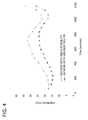
- FIG. 4 illustrates the impedance of the two electrochemical cells of this example.
- the impedance for the single cell using conventional components is shown by open symbols, while the impedance for the single cell of one embodiment of the present disclosure using a cathode flooded with electrolyte having a composition of about 36 wt% LiBr, about 6 wt% LiCl, about 48 wt% LiF and about 10 wt% KBr is shown by the solid symbols.
- the improvement in performance in terms of reduced impedance with the new electrolyte described herein is clearly demonstrated.
Landscapes
- Chemical & Material Sciences (AREA)
- Chemical Kinetics & Catalysis (AREA)
- Electrochemistry (AREA)
- General Chemical & Material Sciences (AREA)
- Engineering & Computer Science (AREA)
- Manufacturing & Machinery (AREA)
- Materials Engineering (AREA)
- Inorganic Chemistry (AREA)
- Primary Cells (AREA)
Description
- The field of this disclosure generally relates to electrolyte material for use in thermal batteries and, particularly, to ternary or quaternary electrolyte material that is substantially binder-free. The disclosure also relates to composites of electrodes and electrolytes that contain the electrolyte material and cathode and/or anode material and to batteries that contain the electrolyte material.
- Thermal batteries tend to have relatively long shelf lives, high energy densities, require relatively low maintenance, and can withstand relatively high temperatures. Thermal batteries also tend to provide a short burst of power over a relatively short period of time. The burst may range from less than a second to an hour or more, with power typically ranging from about a watt or less to kilowatts. Such properties make thermal batteries suitable for military (e.g., batteries for missile guidance systems) and space exploration applications. Thermal batteries may also be used in other applications, such as in electric vehicles.
- A typical thermal battery includes an anode, a cathode, an electrolyte-separator containing a solid electrolyte that is non-conductive at ambient temperature, and a pyrotechnic material (e.g., heat pellet as in
Figure 1 which may contain, for example, Fe-KClO4 powder) that provides a heat source to the battery. When battery operation is desired, an external stimulus is applied to the battery. For example, an electrical current may be applied to the battery to set off an electric match or an electro-active squib or a mechanical force (e.g., mechanical shock) may be applied to set off a concussion primer. The external stimulus causes the pyrotechnic material to ignite and begin to heat. Heat produced from the pyrotechnic material causes the previously solid electrolyte to melt and become conductive, which allows the battery to provide power for a desired application. - The anodes of thermal batteries are generally formed of an alkali or alkaline earth metal or alloy. A typical anode includes lithium metal or a lithium alloy, such as lithium aluminum, lithium silicon, or lithium boron.
- Electrolytes for use with thermal batteries often include a eutectic mixture (i.e., a mixture which melts at a temperature lower than each of the individual components) of lithium chloride and potassium chloride and a binder, such as MgO, fumed silica or kaolin), which assists in containing the electrolyte within the thermal battery assembly upon melting, such as by capillary action, surface tension, or both. With typical thermal battery electrolytes, without sufficient binder, the electrolyte material may disperse throughout the battery, causing undesired shunts or short circuits in the cell. Unfortunately, the binder materials tend to be relatively resistant to ionic conduction and thus inclusion of the binder increases the impedance of the battery.
- Cathode material for thermal batteries may vary in accordance with a variety of design parameters and generally includes a metal oxide or metal sulfide. By way of example, iron oxide (FeO4), iron disulfide (FeS2) or cobalt (CoS2) disulfide are often used as cathode material.
- Thermal batteries are often formed using pellet techniques, such that each of the electrolyte, cathode, and heat source are formed into a wafer. In this case, the respective cell component chemicals are processed into powders and the powders are pressed together to form the cell. Each component may be formed as a discrete part, or the anode and/or cathode may include (i.e., be flooded with) electrolyte material to improve the conductivity of the cell.
-
US 5534367 describes an electrolyte, for use in a battery, comprising a eutectic mixture of lithium chloride, lithium bromide, potassium bromide and lithium fluoride. However, the respective amounts differ to those according to the present invention. -
US 2008/299447 describes a molten salt electrolyte, for a battery, the electrolyte comprising lithium chloride, lithium bromide, potassium bromide and lithium fluoride. Lithium fluoride is present in relatively low amounts. -
US 2007/292748 describes a "cathode-less" battery having an electrolyte comprising lithium fluoride, lithium chloride and lithium bromide. -
US 4728590 describes an electrochemical cell. In the Example, the electrolyte contains lithium chloride and lithium bromide and lithium fluoride. - US-H-1335 H (US Statutory Invention Registration) describes an electrochemical cell having an electrolyte composed of lithium chloride, lithium fluoride and lithium bromide.
-
JP 02 061962 - Although conventionally-used electrolyte material (including cathodes or anodes that contain such electrolyte material and including batteries that include the electrolyte material) work relatively well, the binder adds undesired impedance to the cell. Accordingly, there is a continuing need for thermal battery electrolyte material that allows the amount of binder present in the material to be reduced or even eliminated but yet prevents the electrolyte material from dispersing to portions of the cell that may result in shunts or short-circuits. A continuing need also exists for battery components and batteries that incorporate such electrolyte material.
- The present disclosure provides improved electrolyte material for use in thermal batteries including the cathodes and anodes thereof. The ways in which the improved electrolyte, cathode, anode, and battery overcome the shortcomings of the prior art are discussed in more detail below. In general, however, the disclosure provides a substantially binder-free thermal battery electrolyte, and a battery and components thereof, including the substantially binder-free electrolyte material.
- One aspect of the present disclosure is directed to an electrolyte material for use in thermal batteries, the electrolyte material being substantially binder-free. The material includes at least 25 wt% lithium bromide, at least 4 wt% lithium chloride, and at least 42 wt% lithium fluoride, and at least 1 wt% potassium bromide and no more than 12 wt% potassium bromide.
- In another aspect of the present disclosure, a composite electrode-electrolyte for use in a thermal battery includes an electrode and substantially binder-free electrolyte material. The electrode may contain cathode material or anode material. The electrolyte material includes at least 25 wt% lithium bromide, at least 4 wt% lithium chloride, at least 42 wt% lithium fluoride, and at least 1 wt% potassium bromide and no more than 12 wt% potassium bromide.
- In a further aspect, a battery includes an anode material, cathode material and electrolyte material. The electrolyte material is substantially binder-free and includes at least 25 wt% lithium bromide, at least 4 wt% lithium chloride, at least 42 wt% lithium fluoride, and at least 1 wt% potassium bromide and no more than 12 wt% potassium bromide.
- Various refinements exist of the features noted in relation to the above-mentioned aspects of the present disclosure. Further features may also be incorporated in the above-mentioned aspects of the present disclosure as well. These refinements and additional features may exist individually or in any combination. For instance, various features discussed below in relation to any of the illustrated embodiments of the present disclosure may be incorporated into any of the above-described aspects of the present disclosure, alone or in any combination.
- A more complete understanding of the present disclosure may be derived by referring to the detailed description and claims, considered in connection with the figures, wherein like reference numbers refer to similar elements throughout the figures, and:
-
FIG. 1 illustrates an electrochemical device in accordance with various embodiments of the present disclosure. -
FIG. 2 illustrates a voltage trace of a thermal battery cell in accordance with a conventional battery cell. -
FIG. 3 illustrates a voltage trace of a thermal battery cell in accordance with a first embodiment of the disclosure and a conventional battery cell. -
FIG. 4 illustrates an impedance trace of a thermal battery cell in accordance with the first embodiment of the disclosure and a conventional battery cell. - Corresponding reference characters indicate corresponding parts throughout the drawings. Skilled artisans will appreciate that elements in the figures are illustrated for simplicity and clarity and have not necessarily been drawn to scale. For example, the dimensions of some of the elements in the figures may be exaggerated relative to other elements to help to improve understanding of embodiments of the present disclosure.
- The present disclosure generally relates to electrolyte salt formulations suitable for inclusion in components in thermal batteries and to batteries including the electrolyte material.
FIG. 1 illustrates athermal battery 100, in accordance with various embodiments of the disclosure, which includes ananode 102, an electrolyte-separator (electrolyte) 104, and acathode 106. The electrolyte material of the present disclosure is suitable as a constituent in any or all of these battery components. - As used herein, an "electrochemical device" may otherwise be referred to herein as a battery (and in some embodiments, a "thermal battery"), a capacitor, a cell, an electrochemical cell, or the like. It should be understood that these references are not limiting, and any device that involves electron transfer between an electrode and an electrolyte is contemplated within the scope of the present disclosure. Further, an electrochemical device may refer to single or multiple connected electrochemical devices, electrochemical cells, batteries or capacitors capable of supplying energy to a load, and none of the references herein to any particular device should be considered to limit the disclosure in any way.
- In accordance with various embodiments of the disclosure,
thermal battery 100 components are prepared by consolidating powders via a mechanical pressing operation to produce pellets (i.e., wafers). Thermal batteries using pressed components are prepared by assembling in stacks the various components such as theanode 102, electrolyte-separator 104, andcathode 106, plus a heat source pellet if applicable to the particular battery design. Assembly of one each ofanode 102, electrolyte-separator 104, andcathode 106 comprises a single electrochemical cell. Multiple cells may be stacked in series to produce a thermal battery. In this regard it should be understood that thermal battery designs other than as shown inFigure 1 may be used without departing from the scope of the present disclosure. - Thermal battery anode materials in accordance with various embodiments of the disclosure include any suitable alkaline earth metal or alkali metal. By way of example, the anode includes lithium or lithium alloys, such as lithium aluminum, lithium silicon, and lithium boron alloys. For lithium alloys, the alloy is typically a powdered form. In order to improve performance of a thermal battery, for example, extend the life of the battery for a given amount of anode material, the anode may be "flooded" to form an anode-electrolyte composite wherein electrolyte salt is mixed with the lithium alloy powder and is part of the anode pellet that is pressed. The flooding allows ions to flow not just from the inner edge of the anode but from the bulk of the anode pellet.
- Cathode materials can be prepared in the same or similar manner as anode materials, such that powders are mixed and pressed. In accordance with various embodiments of the disclosure, the cathode includes a metal compound, such as a metal oxide (e.g., FeO4) or metal sulfide (e.g., FeS2, CoS2 or mixtures thereof) as the active material in the cathode. Suitable cathode materials may also include an amount of a bimetal sulfide compound such as, for example, CuFeS2.
- Similar to anode powders, cathode sulfide powders may be mixed with an electrolyte salt to provide a flooded cathode to improve battery performance. As set forth in more detail below, inclusion of the electrolyte, in accordance with exemplary embodiments of the disclosure, into the cathode pellets of a thermal battery so as to form a cathode-electrolyte composite, improves the performance of a single cell containing a stack of anode pellet, electrolyte separator pellet and cathode pellet. The performance improvement is evident in the reduced cell impedance of the stack compared to a cathode using a conventional electrolyte.
- In accordance with various embodiments of the disclosure, electrolyte material that does not include a binder (or is substantially binder-free) is used as the electrolyte-separator, is included in the anode material, and/or is included in the cathode material so as to form an electrode-electrolyte composite. In accordance with additional embodiments, the substantially binder-free electrolyte material may be incorporated into one or more battery components and alternative electrolyte material may be included in one or more of the other battery components.
- In this regard it is to be noted that, as used herein, a "binder-less" electrolyte material (or, alternatively, an electrolyte material "substantially binder-free") generally refers to an electrolyte that contains essentially no conventional binder, such as, for example, MgO, fumed silica or clay minerals such as kaolinite (including kaolin clays which are known to be rich in kaolinite). For example, in various embodiments, the electrolyte material may contain less than about 5 wt% binder, less than about 3 wt%, less than about 1 wt%, less than about 0.1 wt% or even no amount of binder (based on the total weight of the electrolyte material). Alternatively or in addition, the sum of the concentrations of the electrolyte material components (e.g., lithium bromide, lithium chloride, lithium fluoride, and potassium bromide) may be at least about 95 wt%, at least about 96 wt%, at least about 97 wt%, at least about 98 wt%, at least about 99 wt% or even about 100 wt% (based on the total weight of the electrolyte material). Accordingly, in these or other embodiments, the electrolyte material may consist of the recited components (the electrolyte material being, for example, a quaternary mixture of essentially four components) or consist essentially of these components (i.e., the material does not contain materials that are generally electrically conductive other than the recited components).
- As previously noted, conventional electrolyte salts in thermal batteries include a binder material to serve as a static support after activation. While the salt is an inert solid at low temperatures, activation of the battery either through external heating or by inclusion of heat-generating material (for example, Fe-KClO4 powder) raises the temperature such that the electrolyte melts and ionic conduction is possible between the anode and cathode. Conventional molten salts includes a binder material (e.g., MgO, fumed silica or kaolin) to ensure continued separation of the anode and cathode, without which the cell or battery would experience a short circuit and cease to function upon activation. In contrast, the chemistry of the present electrolyte is such that, after activation, the flowability of the molten salt is less than that of other salts used in thermal batteries, allowing the amount of binder to be minimized and even substantially eliminated.
- In this regard, without being bound to any particular theory, it is believed that when electrolyte materials that contain significant amounts of lithium fluoride (e.g., at least about 42 wt% as discussed below) are heated, a portion of the lithium fluoride may remain in the solid-state which increases the viscosity of the electrolyte material as a whole which allows the binder to be eliminated from the material. Lithium fluoride is characterized by a relatively higher melting temperature as compared to other electrolyte salts which allows portions of the lithium fluoride to remain in solid form.
- Various exemplary electrolyte compositions, in accordance with various embodiments of the disclosure, include a salt mixture of lithium bromide (LiBr), lithium chloride (LiCl), lithium fluoride (LiF) and, potassium bromide (KBr). The ratio of the four salts may vary, with preferred embodiments being in the ranges shown below.
Table 3: Exemplary compositions for electrolyte materials Component Exemplary Wt% Exemplary Wt% Exemplary Wt% Exemplary Wt% KBr 0-12 1-9 1-3 9-12 LiBr 25-41 25-41 30-38 32-39 LiCl 4-14 4-14 9-12 5-7 LiF 42-64 42-64 50-60 42-53 - In this regard it is to be noted that, more generally, the electrolyte material may contain, in various exemplary embodiments: at least about 25 wt% lithium bromide, at least about 30 wt%, at least about 35 wt%, or even at least about 40 wt% lithium bromide; at least about 4 wt% lithium chloride, at least about 6 wt%, at least about 8 wt%, at least about 10 wt%, or even at least about 12 wt% lithium chloride; at least about 42 wt% lithium fluoride, at least about 45 wt%, at least about 50 wt%, at least about 55 wt%, or even at least about 60 wt% lithium fluoride; and at least about 1 wt% potassium bromide, at least about 2 wt%, at least about 4 wt%, at least about 8 wt%, or even at least about 10 wt% potassium bromide. It is to be further noted that, in these or other exemplary embodiments, the electrolyte material may contain: no more than about 41 wt% lithium bromide; no more than about 14 wt% lithium chloride; no more than about 64 wt% lithium fluoride. The electrolyte material contains no more than about 12 wt% potassium bromide. Finally, it is to be noted that, in one or more of the embodiments detailed herein, the concentration of a recited component may be within a range bounded by any combination or permutation of the higher and lower concentration limits noted herein (e.g., between about 25 wt% and about 41 wt%, or between about 30 wt% and about 41 wt% lithium bromide), without departing from the intended scope of the present disclosure.
- In accordance with various embodiments of the disclosure, electrolyte material may be formed by measuring a desired amount of each salt in the composition, physically mixing the salts, fusing the mixed material at high temperature (e.g., about 500°C ± about 50°C), grinding the fused electrolyte, and passing the ground product through a sieve. Generally, the size of the particles of the electrolyte material is not critical; however, the particle size should be consistent with typical battery manufacturing operations as dependent on the battery design as appreciated by those of skill in the art. For example, tape casting methods generally use smaller particles than pellet pressing methods. When pellet pressing methods are used to form the electrolyte material (such as when the electrolyte material is used to flood a cathode or anode), the electrolyte particles should be screened such that they are sufficiently small to allow proper filling of the die but yet large enough such that they do not infiltrate the gap between the punch and the die. In tape casting methods, the particles should be sufficiently small to allow casting of a thin tape. Suitable particle size ranges may be readily determined by those of skill in the art.
- The starting salt materials may be either in powder or granulated form and are preferably dried at a temperature sufficient to remove an amount of absorbed moisture (if any). Moisture may be removed as much as economically practical and as much as practical in view of the selected manufacturing process. Generally, the amount of moisture should be reduced to a level that does not cause unacceptable amounts of anode material oxidation. In some embodiments of the present disclosure, the electrolyte salt material may be heated, for example to a temperature of from about 100°C to about 400°C, to remove moisture from the material.
- Physical mixing may proceed via any mechanical mixing method, for example, stirring the salts by hand, agitating the ingredients in a Turbula blender, rolling the container on a jar mill, or the like. Mixing may proceed from 15 minutes to about 2 hours, depending on the total amount of salt and the manner of mixing.
- After the mixing is completed, the mixed powder may be removed from the mixing container and placed into a crucible suitable for fusing the salts at high temperature. Exemplary crucibles may be formed of refractory material that is able to withstand the high temperatures required to fuse the salts and be resistant to the corrosive effects of the molten salts. Salts are fused at a temperature sufficient to melt the bulk of the material such as, for example, at least about 500°C or even at least about 650°C. In accordance with various aspects of these embodiments, depending on the ratio of salts, only a portion of the mixture might fully melt during the fusing process.
- After fusing, the resulting fused salt is ground. Grinding may take place either by hand using a mortar-pestle for small amounts, or using a large grinder such as a quaker mill for large amounts. After grinding, the ground fused salt is passed through a screen to remove any large particles that were missed in the grinding step. The large particles may be ground a second time to reduce their size to pass through the screen. Mesh size of the screen is variable according to the preferences of the user and the intended application.
- The resulting powder, after mixing, fusing, grinding and sieving, may then be pressed into pellets (i.e., wafers) for use as electrolyte-separator or mixed into cathode powders and/or anode powders to form an electrode-electrolyte composite and serve as the flooding electrolyte in those components. The pellets may be formed by a hydraulic press in which the powder material is introduced into a pellet die and leveled (either mechanically or by hand). A hydraulic punch is lowered and compresses the powder into a pellet (i.e., wafer). Pelletting pressures are not critical; however, it is preferred to use pressures near the the highest capable pressures in the pelleting equipment within the mechanical limits of the equipment (e.g., the punch and die materials).
- The following non-limiting examples set forth below are illustrative of various aspects of certain exemplary embodiments of the present disclosure. The compositions, methods and various parameters reflected therein are intended only to exemplify various aspects and embodiments of the disclosure, and are not intended to limit the scope of the claimed disclosure.
-
FIG. 1 shows a stack arrangement of a thermal battery, including heat pellet 108 that would be used to melt the electrolyte upon battery activation. This arrangement, without heat pellet 108, was used for the single cell tests discussed in the Examples. -
Fig. 2 illustrates a voltage trace from a single electrochemical cell including an electrolyte material, in accordance with embodiments of the disclosure, as the electrolyte-separator pellet. The composition of the electrolyte-separator of this cell was about 34 wt% LiBr, about 11 wt% LiCl, about 55 wt% LiF, and 0 wt% KBr. The cathode of the cell was an FeS2 pellet flooded with a conventional KC1-LiCl eutectic electrolyte. The anode was a lithium-silicon alloy powder flooded with a conventional KCl-LiCl eutectic electrolyte. In accordance with the single cell test, the cell stack was heated to a temperature of 500°C under compression to hold the pellets in contact with one another. A current draw of 1 ampere base load was applied with pulses of 5 amperes for 1 second duration applied every 60 seconds. The pulses appear as dips in the voltage trace. The single cell test did not short or experience an abnormally abbreviated life, which indicates the utility of the new electrolyte to serve as an electrolyte-separator pellet in a thermal battery. -
FIG. 3 illustrates voltage traces from two different single cell tests. The upper trace is from a single cell test using only conventional components, that is, the electrolyte of the present disclosure is not present in any of the three cell components; the cathode and anode are as described in Example 1 while the electrolyte separator is a fused electrolyte mixture of LiBr-LiCl-LiF bound with MgO. The lower voltage trace (for which the voltage values were all subtracted by 0.25V to allow both traces to be seen without overlap; that is, the actual voltage values for the lower trace shown inFIG. 3 are 0.25V greater than the values shown) shows a single cell test for which the cathode is flooded using binder-free electrolyte material having a composition of about 36 wt% LiBr, about 6 wt% LiCl, about 48 wt% LiF, and about 10 wt% KBr. -
FIG. 4 illustrates the impedance of the two electrochemical cells of this example. The single cell test conditions were the same as those described in Example 1. This impedance was computed using the negative quotient of the change in voltage from the last data point prior to each pulse to the first data point collected during the pulse, divided by the current values for those same points. The following equation was used for determining the impedance:
- The impedance for the single cell using conventional components is shown by open symbols, while the impedance for the single cell of one embodiment of the present disclosure using a cathode flooded with electrolyte having a composition of about 36 wt% LiBr, about 6 wt% LiCl, about 48 wt% LiF and about 10 wt% KBr is shown by the solid symbols. The improvement in performance in terms of reduced impedance with the new electrolyte described herein is clearly demonstrated.
- Benefits, other advantages, and solutions to problems have been described herein with regard to specific embodiments. However, the benefits, advantages, solutions to problems, and any elements that may cause any benefit, advantage, or solution to occur or become more pronounced are not to be construed as critical, required, or essential features or elements of the disclosure. The scope of the disclosure is accordingly to be limited by nothing other than the claims that may be included in an application that claims the benefit of the present application, in which reference to an element in the singular is not intended to mean "one and only one" unless explicitly so stated, but rather "one or more." Moreover, where a phrase similar to "at least one of A, B, and C" may be used in the claims, it is intended that the phrase be interpreted to mean that A alone may be present in an embodiment, B alone may be present in an embodiment, C alone may be present in an embodiment, or that any combination of the elements A, B and C may be present in a single embodiment; for example, A and B, A and C, B and C, or A and B and C.
Claims (13)
- An electrolyte material for use in thermal batteries, the electrolyte material being substantially binder- free and comprising:at least 25 wt% lithium bromide;at least 4 wt% lithium chloride;at least 42 wt% lithium fluoride; andat least 1 wt% potassium bromide and no more than 12 wt% potassium bromide.
- The electrolyte material as set forth in claim 1 wherein the electrolyte material comprises:no more than 41 wt% lithium bromide;no more than 14 wt% lithium chloride; andno more than 64 wt% lithium fluoride.
- A composite electrode-electrolyte for use in a thermal battery, the composite electrode-electrolyte comprising:an electrode comprising cathode material or anode material; andsubstantially binder-free electrolyte material, the electrolyte material comprising:at least 25 wt% lithium bromide;at least 4 wt% lithium chloride;at least 42 wt% lithium fluoride; andat least 1 wt% potassium bromide and no more than 12 wt% potassium bromide.
- The composite electrode-electrolyte as set forth in claim 3, wherein the electrode comprises cathode material, the cathode material being selected from the group consisting of FeS2, CoS2 and mixtures thereof.
- The composite electrode-electrolyte as set forth in claim 3, wherein the electrode comprises anode material, the anode material being selected from the group consisting of lithium, lithium alloys and mixtures thereof.
- A battery comprising anode material, cathode material, and electrolyte material, the electrolyte material being substantially binder-free and comprising:at least 25 wt% lithium bromide;at least 4 wt% lithium chloride;at least 42 wt% lithium fluoride; andat least 1 wt% potassium bromide and no more than 12 wt% potassium bromide.
- The battery as set forth in claim 6, wherein the lithium bromide, lithium chloride, lithium fluoride and potassium bromide form a eutectic mixture.
- The battery as set forth in any one of the preceding claims, wherein the electrolyte material is substantially MgO-free.
- The battery as set forth in any one of the preceding claims, wherein
the electrolyte material comprises less than 0.1 wt% binder. - The battery as set forth in any one of the preceding claims, wherein
the electrolyte material consists essentially of lithium bromide, lithium chloride, lithium fluoride and any potassium bromide present in the electrolyte material. - The battery as set forth in any one of claims 6 to 10, wherein the electrolyte material comprises:no more than 41 wt% lithium bromide;no more than 14 wt% lithium chloride; andno more than 64 wt% lithium fluoride, preferably wherein the electrolyte material and cathode material form a composite cathode-electrolyte and the cathode material is selected from the group consisting of FeS2, CoS2 and mixtures thereof, preferably wherein the electrolyte material and anode material form a composite anode-electrolyte and the anode material is selected from the group consisting of lithium, lithium alloys and mixtures thereof.
- The battery as set forth in any one of claims 6 to 11, wherein the electrolyte material forms part of an electrolyte separator, preferably wherein the battery is a thermal battery and comprises pyrotechnic material.
- The battery as set forth in any one of claims 6 to 12, wherein the cathode material, anode material and electrolyte material form an electrochemical cell and wherein the battery comprises a plurality of electrochemical cells.
Applications Claiming Priority (2)
| Application Number | Priority Date | Filing Date | Title |
|---|---|---|---|
| US16704009P | 2009-04-06 | 2009-04-06 | |
| PCT/US2010/029980 WO2010117954A1 (en) | 2009-04-06 | 2010-04-05 | Thermal battery electrolyte compositions, electrode-electrolyte composites, and batteries including the same |
Publications (2)
| Publication Number | Publication Date |
|---|---|
| EP2417658A1 EP2417658A1 (en) | 2012-02-15 |
| EP2417658B1 true EP2417658B1 (en) | 2015-08-19 |
Family
ID=42152019
Family Applications (1)
| Application Number | Title | Priority Date | Filing Date |
|---|---|---|---|
| EP10712866.2A Active EP2417658B1 (en) | 2009-04-06 | 2010-04-05 | Thermal battery electrolyte compositions, electrode-electrolyte composites, and batteries including the same |
Country Status (4)
| Country | Link |
|---|---|
| US (1) | US8394520B2 (en) |
| EP (1) | EP2417658B1 (en) |
| JP (1) | JP5492977B2 (en) |
| WO (1) | WO2010117954A1 (en) |
Cited By (3)
| Publication number | Priority date | Publication date | Assignee | Title |
|---|---|---|---|---|
| RU2645763C1 (en) * | 2016-08-24 | 2018-02-28 | федеральное государственное бюджетное образовательное учреждение высшего образования "Самарский государственный технический университет" | Fused electrolyte for chemical current source |
| KR101856839B1 (en) * | 2016-04-21 | 2018-06-19 | 국방과학연구소 | Thin electrode for thermal batteries and a manufacturing method therefor |
| RU2778349C1 (en) * | 2021-06-30 | 2022-08-17 | федеральное государственное бюджетное образовательное учреждение высшего образования "Самарский государственный технический университет" | Molten electrolyte for a chemical current source |
Families Citing this family (17)
| Publication number | Priority date | Publication date | Assignee | Title |
|---|---|---|---|---|
| US8669007B2 (en) * | 2008-11-07 | 2014-03-11 | Eaglepicher Technologies, LLC. | Non-aqueous cell having amorphous or semi-crystalline copper manganese oxide cathode material |
| US8663825B2 (en) | 2009-03-05 | 2014-03-04 | Eaglepicher Technologies, Llc | End of life indication system and method for non-aqueous cell having amorphous or semi-crystalline copper manganese oxide cathode material |
| JP5528534B2 (en) * | 2009-03-18 | 2014-06-25 | イーグルピッチャー テクノロジーズ,エルエルシー | Non-aqueous electrochemical cell having a mixture of at least three cathode materials |
| WO2010117954A1 (en) | 2009-04-06 | 2010-10-14 | Eaglepicher Technologies, Llc | Thermal battery electrolyte compositions, electrode-electrolyte composites, and batteries including the same |
| US8440342B2 (en) * | 2009-04-06 | 2013-05-14 | Eaglepicher Technologies, Llc | Thermal battery cathode materials and batteries including same |
| US8652674B2 (en) | 2010-06-24 | 2014-02-18 | Eaglepicher Technologies, Llc | Thermal battery cathode materials containing nickel disulfide and batteries including same |
| RU2489777C1 (en) * | 2012-01-18 | 2013-08-10 | Федеральное государственное бюджетное образовательное учреждение высшего профессионального образования "Самарский государственный технический университет" | Molten electrolyte for chemical current source |
| CN102867970A (en) * | 2012-09-26 | 2013-01-09 | 沈阳理工大学 | Preparation and test method for unit cell of thermal battery |
| US10340531B2 (en) * | 2013-03-08 | 2019-07-02 | Eaglepicher Technologies Llc | Li—Si—Sn alloy, anode material of the alloy, and batteries including same |
| US10446853B2 (en) | 2014-09-11 | 2019-10-15 | Cfd Research Corporation | Fluorine-based cathode materials for thermal batteries |
| US11094945B2 (en) | 2014-09-11 | 2021-08-17 | Cfd Research Corporation | Thermal battery electrolyte materials |
| US10158148B2 (en) * | 2015-02-18 | 2018-12-18 | Microsoft Technology Licensing, Llc | Dynamically changing internal state of a battery |
| KR101736903B1 (en) | 2015-05-18 | 2017-05-17 | 국방과학연구소 | Method for manufacturing of multi-junction pellet of thermal battery for preventing crack |
| RU2633360C2 (en) * | 2015-12-23 | 2017-10-12 | федеральное государственное бюджетное образовательное учреждение высшего образования "Самарский государственный технический университет" | Melted electrolyte for chemical current source |
| KR102221091B1 (en) * | 2019-06-04 | 2021-02-26 | 국방과학연구소 | Current collector comprising heat source, thermal battery and method for producing thereof |
| RU2768250C1 (en) * | 2021-06-30 | 2022-03-23 | федеральное государственное бюджетное образовательное учреждение высшего образования "Самарский государственный технический университет" | Electrolyte for chemical current source |
| CN113991248A (en) * | 2021-10-27 | 2022-01-28 | 中国工程物理研究院电子工程研究所 | Diaphragm for thermal battery loaded with molten salt electrolyte and preparation method and application thereof |
Family Cites Families (39)
| Publication number | Priority date | Publication date | Assignee | Title |
|---|---|---|---|---|
| US3898096A (en) * | 1973-06-11 | 1975-08-05 | Rockwell International Corp | Lithium-molten salt cell with transition metal chalcogenide positive electrode |
| US3992222A (en) * | 1975-07-15 | 1976-11-16 | The United States Of America As Represented By The United States Energy Research And Development Administration | Metallic sulfide additives for positive electrode material within a secondary electrochemical cell |
| JPS5539146A (en) * | 1978-09-14 | 1980-03-18 | Hitachi Ltd | Primary cell |
| US4608324A (en) | 1983-11-10 | 1986-08-26 | Matsushita Electric Industrial Co., Ltd. | Organic electrolyte cell |
| JPS61135056A (en) | 1984-12-05 | 1986-06-23 | Matsushita Electric Ind Co Ltd | Manufacturing method of organic electrolyte battery |
| US4728590A (en) * | 1986-07-28 | 1988-03-01 | The United States Of America As Represented By The United States Department Of Energy | Electrochemical cell with high discharge/charge rate capability |
| JP2643344B2 (en) * | 1988-08-26 | 1997-08-20 | 日本電池株式会社 | Lithium-based thermal battery |
| JP2680673B2 (en) | 1989-04-07 | 1997-11-19 | 三洋電機株式会社 | Non-aqueous electrolyte battery manufacturing method |
| US4954403A (en) | 1990-02-12 | 1990-09-04 | The United States Of America As Represented By The Secretary Of The Army | High temperature molten salt thermal electrochemical cell |
| GB9006919D0 (en) * | 1990-03-28 | 1990-05-23 | Panther Giles | Paging receiver |
| US5180642A (en) * | 1992-02-24 | 1993-01-19 | Medtronic, Inc. | Electrochemical cells with end-of-service indicator |
| USH1335H (en) * | 1993-02-08 | 1994-07-05 | The United States Of America As Represented By The Secretary Of The Army | High temperature molten salt thermal cell |
| US5534367A (en) * | 1993-12-28 | 1996-07-09 | University Of Chicago | Molten salt electrolyte separator |
| US5736275A (en) * | 1996-04-30 | 1998-04-07 | The University Of Chicago | High power bipolar battery/cells with enhanced overcharge tolerance |
| US5667916A (en) * | 1996-05-10 | 1997-09-16 | Wilson Greatbatch Ltd. | Mixed cathode formulation for achieving end-of-life indication |
| JP3777582B2 (en) * | 1996-12-13 | 2006-05-24 | 株式会社ジーエス・ユアサコーポレーション | Thermal battery |
| US6580908B1 (en) | 1997-07-16 | 2003-06-17 | Mark W. Kroll | Generic number cellular telephone |
| US6465129B1 (en) * | 1998-05-01 | 2002-10-15 | Regents Of The University Of Minnesota | Lithium batteries with new manganese oxide materials as lithium intercalation hosts |
| US6926997B2 (en) | 1998-11-02 | 2005-08-09 | Sandia Corporation | Energy storage and conversion devices using thermal sprayed electrodes |
| US6475662B1 (en) * | 2000-06-05 | 2002-11-05 | Eagle-Picher Technologies, Llc | Thermal battery |
| US7351500B2 (en) * | 2000-11-16 | 2008-04-01 | Hitachi Maxell, Ltd. | Lithium-containing composite oxide and nonaqueous secondary cell using the same, and method for manufacturing the same |
| US6692865B2 (en) | 2000-11-17 | 2004-02-17 | Wilson Greatbatch Ltd. | Double current collector cathode design using mixtures of two active materials for alkali metal or ion electrochemical cells |
| US20070292748A1 (en) * | 2001-05-06 | 2007-12-20 | Rafael-Armament Development Authority Ltd. | Thermal batteries using cathode-precursor pyrotechnic pellets |
| US6936379B2 (en) * | 2001-11-09 | 2005-08-30 | Wilson Greatbatch Technologies, Inc. | Method for electrode design for implantable device applications that require the elective replacement indicator (ERI) |
| US20030228520A1 (en) | 2002-06-06 | 2003-12-11 | Kaun Thomas D. | Process for manufacturing thermal battery with thin fiber separator |
| US7045249B2 (en) * | 2003-07-02 | 2006-05-16 | The Gillette Company | Lithium cell with improved cathode |
| US7194308B2 (en) * | 2003-11-12 | 2007-03-20 | Cardiac Pacemakers, Inc. | System and method for monitoring or reporting battery status of implantable medical device |
| CN101019252A (en) | 2003-12-10 | 2007-08-15 | 罗福科公司 | High Capacity Alkaline Batteries with Cathode Extender |
| US20050227146A1 (en) * | 2003-12-12 | 2005-10-13 | Dania Ghantous | Medium rate and high rate batteries |
| US7476467B2 (en) * | 2004-03-29 | 2009-01-13 | Lg Chem, Ltd. | Lithium secondary battery with high power |
| CN1855587B (en) * | 2005-04-28 | 2010-05-05 | 比亚迪股份有限公司 | Battery anode preparation method and preparation method of lithium ion batteries using the battery anode |
| US20070077488A1 (en) * | 2005-10-04 | 2007-04-05 | Kaimin Chen | Power capability of a cathode |
| US20070099080A1 (en) | 2005-10-28 | 2007-05-03 | Pickett David F Jr | Thermal battery with reduced operational temperature |
| EP1892780A3 (en) * | 2006-08-23 | 2010-11-10 | Rovcal, Inc. | Copper-manganese mixed oxide cathode material for use in alkaline cells having high capacity |
| US8221912B2 (en) * | 2007-05-25 | 2012-07-17 | Panasonic Corporation | Molten salt and thermal battery |
| JP5362261B2 (en) * | 2007-05-25 | 2013-12-11 | パナソニック株式会社 | Molten salt and thermal battery |
| WO2009014845A2 (en) | 2007-06-28 | 2009-01-29 | Ultralife Corporation | High capacity and high rate lithium cells with cfx-mno2 hybrid cathode |
| JP5522927B2 (en) * | 2008-11-25 | 2014-06-18 | パナソニック株式会社 | Thermal battery electrode and thermal battery including the same |
| WO2010117954A1 (en) | 2009-04-06 | 2010-10-14 | Eaglepicher Technologies, Llc | Thermal battery electrolyte compositions, electrode-electrolyte composites, and batteries including the same |
-
2010
- 2010-04-05 WO PCT/US2010/029980 patent/WO2010117954A1/en not_active Ceased
- 2010-04-05 US US12/754,405 patent/US8394520B2/en active Active
- 2010-04-05 EP EP10712866.2A patent/EP2417658B1/en active Active
- 2010-04-05 JP JP2012504751A patent/JP5492977B2/en active Active
Cited By (3)
| Publication number | Priority date | Publication date | Assignee | Title |
|---|---|---|---|---|
| KR101856839B1 (en) * | 2016-04-21 | 2018-06-19 | 국방과학연구소 | Thin electrode for thermal batteries and a manufacturing method therefor |
| RU2645763C1 (en) * | 2016-08-24 | 2018-02-28 | федеральное государственное бюджетное образовательное учреждение высшего образования "Самарский государственный технический университет" | Fused electrolyte for chemical current source |
| RU2778349C1 (en) * | 2021-06-30 | 2022-08-17 | федеральное государственное бюджетное образовательное учреждение высшего образования "Самарский государственный технический университет" | Molten electrolyte for a chemical current source |
Also Published As
| Publication number | Publication date |
|---|---|
| US8394520B2 (en) | 2013-03-12 |
| JP5492977B2 (en) | 2014-05-14 |
| US20100310917A1 (en) | 2010-12-09 |
| EP2417658A1 (en) | 2012-02-15 |
| WO2010117954A1 (en) | 2010-10-14 |
| JP2012523099A (en) | 2012-09-27 |
Similar Documents
| Publication | Publication Date | Title |
|---|---|---|
| US8394520B2 (en) | Thermal battery electrolyte materials, electrode-electrolyte composites, and batteries including same | |
| EP2417656B1 (en) | Thermal battery cathode materials and batteries including same | |
| EP2400585B1 (en) | Thermal battery cathode materials containing nickel disulfide and batteries including same | |
| EP2573850B1 (en) | Electrolyte materials, thermal battery components, and thermal batteries for intermediate temperature applications | |
| EP2306580B1 (en) | Composition and energy storage device | |
| US6544691B1 (en) | Batteries using molten salt electrolyte | |
| CA1235262A (en) | Isostatic compression method for producing solid state electrochemical cells | |
| JP3332133B2 (en) | All-solid lithium secondary battery | |
| US4221849A (en) | Iron-lithium anode for thermal batteries and thermal batteries made therefrom | |
| KR20190077553A (en) | Stable low-voltage electrochemical cell | |
| US5085955A (en) | Non-aqueous electrochemical cell | |
| CA1045680A (en) | Lithium-silicon electrode for rechargeable cell | |
| US3998658A (en) | High voltage organic electrolyte batteries | |
| US10340531B2 (en) | Li—Si—Sn alloy, anode material of the alloy, and batteries including same | |
| Guidotti | Thermal batteries: A technology review and future directions | |
| US4474863A (en) | High energy ambient temperature inorganic electrochemical power cell | |
| Dai et al. | Evaluation of a LiSi/Cu3V2O8 Thermal Battery | |
| Seefurth et al. | Current Collectors for Lithium‐Silicon Electrodes in Lithium/Iron Disulfide Cells | |
| Dickinson | Room temperature cells with solid electrolytes | |
| KR20200089495A (en) | Anode material of Lithium ion battery and method of preparing the same |
Legal Events
| Date | Code | Title | Description |
|---|---|---|---|
| PUAI | Public reference made under article 153(3) epc to a published international application that has entered the european phase |
Free format text: ORIGINAL CODE: 0009012 |
|
| 17P | Request for examination filed |
Effective date: 20111028 |
|
| AK | Designated contracting states |
Kind code of ref document: A1 Designated state(s): AT BE BG CH CY CZ DE DK EE ES FI FR GB GR HR HU IE IS IT LI LT LU LV MC MK MT NL NO PL PT RO SE SI SK SM TR |
|
| RAP1 | Party data changed (applicant data changed or rights of an application transferred) |
Owner name: EAGLEPICHER TECHNOLOGIES, LLC |
|
| DAX | Request for extension of the european patent (deleted) | ||
| 17Q | First examination report despatched |
Effective date: 20140610 |
|
| REG | Reference to a national code |
Ref country code: DE Ref legal event code: R079 Ref document number: 602010026787 Country of ref document: DE Free format text: PREVIOUS MAIN CLASS: H01M0006360000 Ipc: H01M0004380000 |
|
| GRAP | Despatch of communication of intention to grant a patent |
Free format text: ORIGINAL CODE: EPIDOSNIGR1 |
|
| RIC1 | Information provided on ipc code assigned before grant |
Ipc: H01M 6/20 20060101ALI20150227BHEP Ipc: H01M 6/36 20060101ALI20150227BHEP Ipc: H01M 4/38 20060101AFI20150227BHEP Ipc: H01M 4/40 20060101ALN20150227BHEP Ipc: H01M 6/18 20060101ALI20150227BHEP Ipc: H01M 4/58 20100101ALI20150227BHEP |
|
| INTG | Intention to grant announced |
Effective date: 20150320 |
|
| GRAS | Grant fee paid |
Free format text: ORIGINAL CODE: EPIDOSNIGR3 |
|
| GRAA | (expected) grant |
Free format text: ORIGINAL CODE: 0009210 |
|
| AK | Designated contracting states |
Kind code of ref document: B1 Designated state(s): AT BE BG CH CY CZ DE DK EE ES FI FR GB GR HR HU IE IS IT LI LT LU LV MC MK MT NL NO PL PT RO SE SI SK SM TR |
|
| REG | Reference to a national code |
Ref country code: GB Ref legal event code: FG4D |
|
| REG | Reference to a national code |
Ref country code: CH Ref legal event code: EP |
|
| REG | Reference to a national code |
Ref country code: IE Ref legal event code: FG4D |
|
| REG | Reference to a national code |
Ref country code: AT Ref legal event code: REF Ref document number: 744356 Country of ref document: AT Kind code of ref document: T Effective date: 20150915 |
|
| REG | Reference to a national code |
Ref country code: DE Ref legal event code: R096 Ref document number: 602010026787 Country of ref document: DE |
|
| REG | Reference to a national code |
Ref country code: AT Ref legal event code: MK05 Ref document number: 744356 Country of ref document: AT Kind code of ref document: T Effective date: 20150819 |
|
| REG | Reference to a national code |
Ref country code: LT Ref legal event code: MG4D |
|
| REG | Reference to a national code |
Ref country code: NL Ref legal event code: MP Effective date: 20150819 |
|
| PG25 | Lapsed in a contracting state [announced via postgrant information from national office to epo] |
Ref country code: LV Free format text: LAPSE BECAUSE OF FAILURE TO SUBMIT A TRANSLATION OF THE DESCRIPTION OR TO PAY THE FEE WITHIN THE PRESCRIBED TIME-LIMIT Effective date: 20150819 Ref country code: GR Free format text: LAPSE BECAUSE OF FAILURE TO SUBMIT A TRANSLATION OF THE DESCRIPTION OR TO PAY THE FEE WITHIN THE PRESCRIBED TIME-LIMIT Effective date: 20151120 Ref country code: NO Free format text: LAPSE BECAUSE OF FAILURE TO SUBMIT A TRANSLATION OF THE DESCRIPTION OR TO PAY THE FEE WITHIN THE PRESCRIBED TIME-LIMIT Effective date: 20151119 Ref country code: FI Free format text: LAPSE BECAUSE OF FAILURE TO SUBMIT A TRANSLATION OF THE DESCRIPTION OR TO PAY THE FEE WITHIN THE PRESCRIBED TIME-LIMIT Effective date: 20150819 Ref country code: LT Free format text: LAPSE BECAUSE OF FAILURE TO SUBMIT A TRANSLATION OF THE DESCRIPTION OR TO PAY THE FEE WITHIN THE PRESCRIBED TIME-LIMIT Effective date: 20150819 |
|
| PG25 | Lapsed in a contracting state [announced via postgrant information from national office to epo] |
Ref country code: IS Free format text: LAPSE BECAUSE OF FAILURE TO SUBMIT A TRANSLATION OF THE DESCRIPTION OR TO PAY THE FEE WITHIN THE PRESCRIBED TIME-LIMIT Effective date: 20151219 Ref country code: SE Free format text: LAPSE BECAUSE OF FAILURE TO SUBMIT A TRANSLATION OF THE DESCRIPTION OR TO PAY THE FEE WITHIN THE PRESCRIBED TIME-LIMIT Effective date: 20150819 Ref country code: PL Free format text: LAPSE BECAUSE OF FAILURE TO SUBMIT A TRANSLATION OF THE DESCRIPTION OR TO PAY THE FEE WITHIN THE PRESCRIBED TIME-LIMIT Effective date: 20150819 Ref country code: AT Free format text: LAPSE BECAUSE OF FAILURE TO SUBMIT A TRANSLATION OF THE DESCRIPTION OR TO PAY THE FEE WITHIN THE PRESCRIBED TIME-LIMIT Effective date: 20150819 Ref country code: ES Free format text: LAPSE BECAUSE OF FAILURE TO SUBMIT A TRANSLATION OF THE DESCRIPTION OR TO PAY THE FEE WITHIN THE PRESCRIBED TIME-LIMIT Effective date: 20150819 Ref country code: PT Free format text: LAPSE BECAUSE OF FAILURE TO SUBMIT A TRANSLATION OF THE DESCRIPTION OR TO PAY THE FEE WITHIN THE PRESCRIBED TIME-LIMIT Effective date: 20151221 |
|
| REG | Reference to a national code |
Ref country code: FR Ref legal event code: PLFP Year of fee payment: 7 |
|
| PG25 | Lapsed in a contracting state [announced via postgrant information from national office to epo] |
Ref country code: NL Free format text: LAPSE BECAUSE OF FAILURE TO SUBMIT A TRANSLATION OF THE DESCRIPTION OR TO PAY THE FEE WITHIN THE PRESCRIBED TIME-LIMIT Effective date: 20150819 |
|
| PG25 | Lapsed in a contracting state [announced via postgrant information from national office to epo] |
Ref country code: DK Free format text: LAPSE BECAUSE OF FAILURE TO SUBMIT A TRANSLATION OF THE DESCRIPTION OR TO PAY THE FEE WITHIN THE PRESCRIBED TIME-LIMIT Effective date: 20150819 Ref country code: CZ Free format text: LAPSE BECAUSE OF FAILURE TO SUBMIT A TRANSLATION OF THE DESCRIPTION OR TO PAY THE FEE WITHIN THE PRESCRIBED TIME-LIMIT Effective date: 20150819 Ref country code: SK Free format text: LAPSE BECAUSE OF FAILURE TO SUBMIT A TRANSLATION OF THE DESCRIPTION OR TO PAY THE FEE WITHIN THE PRESCRIBED TIME-LIMIT Effective date: 20150819 Ref country code: EE Free format text: LAPSE BECAUSE OF FAILURE TO SUBMIT A TRANSLATION OF THE DESCRIPTION OR TO PAY THE FEE WITHIN THE PRESCRIBED TIME-LIMIT Effective date: 20150819 Ref country code: IT Free format text: LAPSE BECAUSE OF FAILURE TO SUBMIT A TRANSLATION OF THE DESCRIPTION OR TO PAY THE FEE WITHIN THE PRESCRIBED TIME-LIMIT Effective date: 20150819 |
|
| REG | Reference to a national code |
Ref country code: DE Ref legal event code: R097 Ref document number: 602010026787 Country of ref document: DE |
|
| PG25 | Lapsed in a contracting state [announced via postgrant information from national office to epo] |
Ref country code: RO Free format text: LAPSE BECAUSE OF FAILURE TO SUBMIT A TRANSLATION OF THE DESCRIPTION OR TO PAY THE FEE WITHIN THE PRESCRIBED TIME-LIMIT Effective date: 20150819 |
|
| PLBE | No opposition filed within time limit |
Free format text: ORIGINAL CODE: 0009261 |
|
| STAA | Information on the status of an ep patent application or granted ep patent |
Free format text: STATUS: NO OPPOSITION FILED WITHIN TIME LIMIT |
|
| 26N | No opposition filed |
Effective date: 20160520 |
|
| PG25 | Lapsed in a contracting state [announced via postgrant information from national office to epo] |
Ref country code: BE Free format text: LAPSE BECAUSE OF NON-PAYMENT OF DUE FEES Effective date: 20160430 Ref country code: SI Free format text: LAPSE BECAUSE OF FAILURE TO SUBMIT A TRANSLATION OF THE DESCRIPTION OR TO PAY THE FEE WITHIN THE PRESCRIBED TIME-LIMIT Effective date: 20150819 |
|
| REG | Reference to a national code |
Ref country code: CH Ref legal event code: PL |
|
| PG25 | Lapsed in a contracting state [announced via postgrant information from national office to epo] |
Ref country code: BE Free format text: LAPSE BECAUSE OF FAILURE TO SUBMIT A TRANSLATION OF THE DESCRIPTION OR TO PAY THE FEE WITHIN THE PRESCRIBED TIME-LIMIT Effective date: 20150819 Ref country code: LU Free format text: LAPSE BECAUSE OF FAILURE TO SUBMIT A TRANSLATION OF THE DESCRIPTION OR TO PAY THE FEE WITHIN THE PRESCRIBED TIME-LIMIT Effective date: 20160405 |
|
| REG | Reference to a national code |
Ref country code: IE Ref legal event code: MM4A |
|
| PG25 | Lapsed in a contracting state [announced via postgrant information from national office to epo] |
Ref country code: LI Free format text: LAPSE BECAUSE OF NON-PAYMENT OF DUE FEES Effective date: 20160430 Ref country code: CH Free format text: LAPSE BECAUSE OF NON-PAYMENT OF DUE FEES Effective date: 20160430 |
|
| REG | Reference to a national code |
Ref country code: FR Ref legal event code: PLFP Year of fee payment: 8 |
|
| PG25 | Lapsed in a contracting state [announced via postgrant information from national office to epo] |
Ref country code: IE Free format text: LAPSE BECAUSE OF NON-PAYMENT OF DUE FEES Effective date: 20160405 |
|
| REG | Reference to a national code |
Ref country code: FR Ref legal event code: PLFP Year of fee payment: 9 |
|
| PG25 | Lapsed in a contracting state [announced via postgrant information from national office to epo] |
Ref country code: HU Free format text: LAPSE BECAUSE OF FAILURE TO SUBMIT A TRANSLATION OF THE DESCRIPTION OR TO PAY THE FEE WITHIN THE PRESCRIBED TIME-LIMIT; INVALID AB INITIO Effective date: 20100405 Ref country code: CY Free format text: LAPSE BECAUSE OF FAILURE TO SUBMIT A TRANSLATION OF THE DESCRIPTION OR TO PAY THE FEE WITHIN THE PRESCRIBED TIME-LIMIT Effective date: 20150819 Ref country code: SM Free format text: LAPSE BECAUSE OF FAILURE TO SUBMIT A TRANSLATION OF THE DESCRIPTION OR TO PAY THE FEE WITHIN THE PRESCRIBED TIME-LIMIT Effective date: 20150819 |
|
| PG25 | Lapsed in a contracting state [announced via postgrant information from national office to epo] |
Ref country code: HR Free format text: LAPSE BECAUSE OF FAILURE TO SUBMIT A TRANSLATION OF THE DESCRIPTION OR TO PAY THE FEE WITHIN THE PRESCRIBED TIME-LIMIT Effective date: 20150819 Ref country code: TR Free format text: LAPSE BECAUSE OF FAILURE TO SUBMIT A TRANSLATION OF THE DESCRIPTION OR TO PAY THE FEE WITHIN THE PRESCRIBED TIME-LIMIT Effective date: 20150819 Ref country code: MC Free format text: LAPSE BECAUSE OF FAILURE TO SUBMIT A TRANSLATION OF THE DESCRIPTION OR TO PAY THE FEE WITHIN THE PRESCRIBED TIME-LIMIT Effective date: 20150819 Ref country code: MT Free format text: LAPSE BECAUSE OF NON-PAYMENT OF DUE FEES Effective date: 20160430 Ref country code: MK Free format text: LAPSE BECAUSE OF FAILURE TO SUBMIT A TRANSLATION OF THE DESCRIPTION OR TO PAY THE FEE WITHIN THE PRESCRIBED TIME-LIMIT Effective date: 20150819 |
|
| PG25 | Lapsed in a contracting state [announced via postgrant information from national office to epo] |
Ref country code: BG Free format text: LAPSE BECAUSE OF FAILURE TO SUBMIT A TRANSLATION OF THE DESCRIPTION OR TO PAY THE FEE WITHIN THE PRESCRIBED TIME-LIMIT Effective date: 20150819 |
|
| P01 | Opt-out of the competence of the unified patent court (upc) registered |
Effective date: 20230530 |
|
| PGFP | Annual fee paid to national office [announced via postgrant information from national office to epo] |
Ref country code: DE Payment date: 20250430 Year of fee payment: 16 |
|
| PGFP | Annual fee paid to national office [announced via postgrant information from national office to epo] |
Ref country code: FR Payment date: 20250429 Year of fee payment: 16 |
|
| PGFP | Annual fee paid to national office [announced via postgrant information from national office to epo] |
Ref country code: GB Payment date: 20260331 Year of fee payment: 17 |