EP2417583B1 - Characterizing items of currency - Google Patents
Characterizing items of currency Download PDFInfo
- Publication number
- EP2417583B1 EP2417583B1 EP10719137.1A EP10719137A EP2417583B1 EP 2417583 B1 EP2417583 B1 EP 2417583B1 EP 10719137 A EP10719137 A EP 10719137A EP 2417583 B1 EP2417583 B1 EP 2417583B1
- Authority
- EP
- European Patent Office
- Prior art keywords
- specified
- sources
- light
- spectrum
- validation apparatus
- Prior art date
- Legal status (The legal status is an assumption and is not a legal conclusion. Google has not performed a legal analysis and makes no representation as to the accuracy of the status listed.)
- Not-in-force
Links
- 238000001228 spectrum Methods 0.000 claims description 72
- 230000006870 function Effects 0.000 claims description 66
- 238000010200 validation analysis Methods 0.000 claims description 63
- 238000000295 emission spectrum Methods 0.000 claims description 20
- OAICVXFJPJFONN-UHFFFAOYSA-N Phosphorus Chemical compound [P] OAICVXFJPJFONN-UHFFFAOYSA-N 0.000 claims description 7
- 239000000203 mixture Substances 0.000 claims description 5
- 238000000034 method Methods 0.000 description 29
- 230000005284 excitation Effects 0.000 description 10
- 239000011159 matrix material Substances 0.000 description 10
- 230000009467 reduction Effects 0.000 description 10
- 230000003595 spectral effect Effects 0.000 description 8
- 230000004044 response Effects 0.000 description 7
- 238000005259 measurement Methods 0.000 description 5
- 230000005540 biological transmission Effects 0.000 description 4
- 239000000463 material Substances 0.000 description 4
- 238000000985 reflectance spectrum Methods 0.000 description 4
- 238000012360 testing method Methods 0.000 description 4
- 238000000354 decomposition reaction Methods 0.000 description 3
- 238000012545 processing Methods 0.000 description 3
- 230000009466 transformation Effects 0.000 description 3
- 238000000411 transmission spectrum Methods 0.000 description 3
- 230000009102 absorption Effects 0.000 description 2
- 238000010521 absorption reaction Methods 0.000 description 2
- 239000003086 colorant Substances 0.000 description 2
- 238000013144 data compression Methods 0.000 description 2
- 238000013461 design Methods 0.000 description 2
- 238000003384 imaging method Methods 0.000 description 2
- 238000004519 manufacturing process Methods 0.000 description 2
- 238000012706 support-vector machine Methods 0.000 description 2
- 238000007906 compression Methods 0.000 description 1
- 230000006835 compression Effects 0.000 description 1
- 238000012986 modification Methods 0.000 description 1
- 230000004048 modification Effects 0.000 description 1
- 230000037361 pathway Effects 0.000 description 1
- 230000008569 process Effects 0.000 description 1
- 239000000126 substance Substances 0.000 description 1
- 238000002834 transmittance Methods 0.000 description 1
- 238000012795 verification Methods 0.000 description 1
- 238000001429 visible spectrum Methods 0.000 description 1
Images






Classifications
-
- G—PHYSICS
- G07—CHECKING-DEVICES
- G07D—HANDLING OF COINS OR VALUABLE PAPERS, e.g. TESTING, SORTING BY DENOMINATIONS, COUNTING, DISPENSING, CHANGING OR DEPOSITING
- G07D7/00—Testing specially adapted to determine the identity or genuineness of valuable papers or for segregating those which are unacceptable, e.g. banknotes that are alien to a currency
- G07D7/06—Testing specially adapted to determine the identity or genuineness of valuable papers or for segregating those which are unacceptable, e.g. banknotes that are alien to a currency using wave or particle radiation
- G07D7/12—Visible light, infrared or ultraviolet radiation
- G07D7/121—Apparatus characterised by sensor details
-
- G—PHYSICS
- G07—CHECKING-DEVICES
- G07D—HANDLING OF COINS OR VALUABLE PAPERS, e.g. TESTING, SORTING BY DENOMINATIONS, COUNTING, DISPENSING, CHANGING OR DEPOSITING
- G07D7/00—Testing specially adapted to determine the identity or genuineness of valuable papers or for segregating those which are unacceptable, e.g. banknotes that are alien to a currency
- G07D7/06—Testing specially adapted to determine the identity or genuineness of valuable papers or for segregating those which are unacceptable, e.g. banknotes that are alien to a currency using wave or particle radiation
- G07D7/12—Visible light, infrared or ultraviolet radiation
- G07D7/1205—Testing spectral properties
Definitions
- the disclosure relates to characterizing items of currency.
- a validation device comprising a validation unit
- a validation unit can be used to characterize an item of currency.
- the term item of currency includes, but is not limited to, valuable papers, security documents, banknotes, checks, bills, certificates, credit cards, debit cards, money cards, gift cards, coupons, coins, tokens, and identification papers.
- the validation unit includes a sensing system often further comprising a source for emitting light and a receiver for receiving the emitted light.
- Validation (i.e., classification) of a currency item can involve the measurement and analysis of one or both of reflected light and light transmitted through a currency item.
- Typical validation units are arranged to use a plurality of light emitting sources (e.g., Light Emitting Diodes (LEDs)) to gather reflective and/or transmission responses from a currency item.
- LEDs Light Emitting Diodes
- these sources are configured such that they emit light within a relatively narrow band of wavelength within a spectrum.
- commonly known sources e.g., red LEDs, blue LEDs, and green LEDs
- Examples of common sources can include red sources emitting light in the range of 640nm to 700nm, blue sources emitting light in the range of 450nm to 480nm, and green sources emitting light in the range of 520nm to 555nm.
- Such common sources are configured to emit light within wavelength bands consistent with known colors within the visible spectrum (e.g., red light, blue light and green light).
- the response of a currency item to being illuminated with sources having emission within known color spectrums of visible light can be used to determine various characteristics about the item of currency.
- infrared light can be used to gather information about characteristics of an item of currency.
- image processing machines e.g., document scanners or photocopiers
- image processing machines which use a plurality of sources and detectors to reproduce or store and image of a document.
- image processing machines In the case of color images, it is often the goal of such image processing machines to gather characteristics from a document such that they can be reproduced to be visually equivalent to the human eye (i.e., discrimination like the human eye is capable of).
- discrimination like the human eye is capable of.
- the fact that the human eye acts like a three color imaging system allows for the design of such image processing machines to be developed that reproduce a color image in a way that the human eye (or any imaging system with similar color limitations) cannot discriminate between the original image and the reproduced image.
- a limitation of some current devices for classifying items of currency is that the typical common sources used result in gaps within the whole spectrum because each source generally emits in a narrow band of spectrum.
- One solution to this problem is to use a very large number of common type sources such that there would be sufficiently enough sources to cover the entire spectrum. This solution is undesirable because it leads to a very large and expensive validation apparatus.
- a device required to process very large amounts of data and thus is not as efficient as required for a currency validation apparatus (e.g., gaming machine, vending, machine, and ticketing machine, etc.) where validation is needed to be made in a relatively short period of time (e.g., less than one second).
- State of the art devices can illuminate a currency item using sources within the validation unit either in a sequential manner (i.e., where each emitter illuminates in a different wavelength band) or simultaneously.
- a validation system is disclosed by U.S. Patent No. 5,632,367 .
- a validation unit can illuminate a currency item using a light bar type system to mix light from a plurality of sources.
- Such a light mixing system is disclosed in U.S. Patent No. 6,994,203 .
- a currency item being characterized by a validation unit can be discriminated in various ways commonly known in the art (e.g., Malahanobis Distance, Feature Vector Selection, or Support Vector Machine). Currency items can be characterized based on their color response as disclosed in currently pending U.S. Provisional Application Serial No. 61/137,386 ( WO 2010/014705 ).
- EP 1 239 423 A2 discloses a bill validator having a funnel-like shaped first light-guide disposed between a bill pathway and a plurality of light sources.
- the validator can validate bills with a high accuracy, and a higher resolution ability by condensing light emitted from a plurality of light sources and narrowing a specific measuring point on the bill surface where transmittance and reflectance of the bill are measured.
- WO 01/61654 A2 discloses methods and devices for testing the colour fastness of objects, such as bank notes, security, identification or value documents for instance, by measuring the light that is issued from an object to be verified and is especially reflected or transmitted, whereby said objects are imprinted with security printing colour.
- the aim of the invention is to guarantee a particularly reliable colour fastness test.
- the light that is issued from the object to be verified is detected in spectral regions which are situated outside a visible spectral region.
- the aim of the invention is also to obtain a user-friendly and secure colour fastness test.
- the light that is issued from the object is detected in several points of the object and in at least two selected spectral regions and a series of measurements is produced for each spectral region respectively. Two series of measurements are adapted to each other and the colour fastness test is subsequently carried out by comparing the two series of measurements, which are adapted to each other.
- WO 03/054809 A2 discloses methods and devices for verifying the authenticity of sheet-type products, particularly banknotes, by using ultraviolet light, whereby the transmitted ultraviolet light, i.e. the ultraviolet light passing through the sheet-like product to be verified, is used for verifying the authenticy.
- the invention relates to a validation apparatus as defined in claim 1.
- the validation apparatus includes a processor and memory unit for characterizing items of currency.
- the validation apparatus includes a transportation unit to move an inserted currency item to and through the validation unit, the transportation unit can be one continuous unit or a plurality of transportation units arranged to form a continuous path through the validation apparatus.
- a method for establishing a reference set of spectrum and applying a dimension reduction technique (e.g., principle component analysis or non-negative matrix factorization) to compress the reference set of spectrum into a second space (i.e., filter space) and obtain a set of approximating functions (i.e., filters) for approximating the reflectance (or transmission) spectrum and reconstructing the original reference spectrum.
- a dimension reduction technique e.g., principle component analysis or non-negative matrix factorization
- a method for establishing at least one specified source whereby the at least one specified source has an emission spectrum similar to an approximating function for reconstructing the original reference set of spectrum.
- a method for using light received e.g., reflected by or transmitted through an item of currency
- a specified source having an emission spectrum similar to an approximating filter for reconstructing the original reference set of spectrum to characterize the currency item inserted into a validation apparatus.
- a validation apparatus including at least one specified source having an emission spectrum similar to an approximating filter for reconstructing the original reference set of spectrum.
- At least one specified source comprises an emitting element and an excitation element, such that energy emitted from the emitting element excites the excitation element to produce an emission spectrum similar to an approximating function for reconstructing the reference spectrum.
- At least one broadband source is coupled to at least one physical element having a transmission spectrum similar to an approximating function for reconstructing the reference spectrum.
- At least one receiver is coupled to at least one physical element having a transmission spectrum similar to an approximating function for reconstructing the reference spectrum.
- the specified sources are Light Emitting Diodes (LED's) coupled to an excitation element containing phosphor (or any other specified component of an excitation element).
- the Light Emitting Diodes are coupled to an excitation element containing a plurality of different phosphors having varying relative amounts (i.e., mixed) of each phosphor in order to produce an emission spectrum similar to an approximating function for reconstructing the original reference spectrum.
- the relative amounts of different phosphors configured in an excitation element are adjusted from the identified amounts to account for losses and/or absorption of energy that result from their combination in order to produce an emission spectrum similar to an approximating function for reconstructing the original spectrum.
- a group of specified sources are arranged such that their emitted light can be mixed in a light mixer (e.g., a light pipe core).
- the intensity of emission for each specified source in the group can be controlled by controlling the excitation current applied thereto.
- the amount of current applied to each specified source arranged in a light pipe configuration can be controlled by software in the validation apparatus.
- the control of currents applied to the plurality of specified sources can be controlled using a processor in the validation apparatus.
- the amount of energy emitted from each of the plurality of specified sources can be controlled by varying the pulses (e.g., pulse width modulation (PWM) or amplitude) applied to each specified source in order to manage the amount of respective light used for mixing in a light pipe.
- PWM pulse width modulation
- the validation apparatus comprises a plurality of specified sources each having an emission spectrum similar to an approximating function for reconstructing the original reference spectrum and at least one receiver for receiving emissions from each specified source.
- the validation apparatus comprises a plurality of broadband sources each having a physical filter associated therewith such that spectrum resulting from each broadband source and each specified physical filter is similar to an approximating function for reconstructing the reference spectrum.
- the validation apparatus comprises a single broadband source and a plurality of receivers each having a specified physical filter associated therewith such that received light by each receiver is comparable to an approximating function for reconstructing the reference spectrum.
- the validation apparatus comprises a plurality of standard sources each having an emission spectrum similar to known colors (e.g., red, green, blue, Infrared) and at least one specified source having an emission spectrum similar to a spectrum related to at least one specific item of currency.
- known colors e.g., red, green, blue, Infrared
- classification of currency items includes, but is not limited to, recognition, verification, validation, authentication and determination of denomination.
- a currency validation system 10 includes a validation unit 100 for classifying currency items (not shown) inserted therein.
- validation unit 100 includes a sensing unit 120 comprised of at least one source 130 and at least one receiver 140.
- sensing unit 120 can be arranged to include at least one light emitting diode (LED) 130 and at least one receiver 140 for receiving light emitted from the LED 130.
- LED 130 emits light in at least one of the visible or the non-visible light spectrum.
- a method is used to determine the number of light sources to be implemented in document handling unit 10. More particularly, a set of reference spectrum associated with at least one currency item 50, or a portion thereof, can be used as inputs to a dimension reduction technique.
- the reference set of spectrum S can be used as inputs to a dimension reduction technique to achieve a form of data compression of the reference spectrum S.
- the reference set of spectrum S is represented by a matrix of spectrum responses.
- a series of spectrum of patches e.g., Munsell Patches or Pantone Patches
- increments e.g., every 1 nm
- a method is used to simulate a reference spectrum, for example to reconstruct the spectrum of a non-authentic document such as a forgery or copy.
- a data reduction technique can be used to reduce the amount of data used to estimate the entire set of original spectrum S.
- data reduction techniques include, but are not limited to Principle Component Analysis (PCA), non-negative matrix factorization (NMF), or dimension selection algorithms.
- PCA Principle Component Analysis
- NMF non-negative matrix factorization
- the entire reference set S (or any subset thereof) can be used for classification.
- a Munsell set of spectra (scanned every 1 nm) is used as inputs to a data reduction technique (or data compression technique).
- a data reduction technique or data compression technique.
- 1269 Munsell patches i.e., a Munsell set
- each scanned every 1nm wavelength from 380nm - 800nm can be used as inputs to the PCA in order to find the most relevant PCA axes.
- the Munsell set is transformed from an original multidimensional space to the PCA space where each axis of the PCA space is a linear combination of all the variables (i.e., a function) from the original space.
- the first few axis of the PCA space explain most of the variance in the original data set (e.g., reference set or Munsell set).
- the weights associated with the newly combined linear combinations (i.e., functions) of the original reference set S can be both negative and non-negative.
- a transformation is needed to establish a new set of filters (i.e., functions) in which all the coefficients are positive.
- Non-negative matrix factorization is an example of another dimension reduction technique which can be used to find a new space (i.e., filter space) with positive coefficients so that the approximating functions are positive and therefore have a physical meaning.
- the variables can be obtained where the coefficients of the functions are the weights obtained by the non-negative matrix factorization.
- These functions can physically be built as filters (or sources) because they have a physical meaning in the sense that all weights are positive.
- the reference set of spectrum S is used to establish a set of functions F. More specifically, the PCA axis are constructed using the reference set S, and then the principle components are transformed into another space (i.e., function space) using the constraint that the new coefficients are all positive.
- a reference set of spectrum S is established in step 200.
- the error of the reconstruction of the reflectance spectrum R is obtained, for example, by using the Frobenius norm (step 230).
- the error of the color reconstruction (step 235) is obtained using the Delta E CIE LAB error between the LAB values, of the real (or reference) spectrum S and the reconstructed spectrum R.
- Use of the error information allows for a comparison of performance in reconstructing the reference spectrum S so that the number of functions in function set F can be determined based on a desired level of performance (or acceptable error). For example, predetermined thresholds or acceptable ranges of error (e.g. Delta E CIE LAB error or Frobenius norm) can be established and the number of functions within function set F can be varied in order to determine the number of functions needed to satisfy the predetermined thresholds for error performance
- F is a set of eigenvectors (i.e., functions).
- the number of eigenvectors i.e., functions
- F can be established in relation to a desired level of performance in reconstructing the reference set of spectrum S.
- F can be a set of 6 eigenvectors (i.e., functions), but any other number of eigenvectors can be used without varying in scope from the present disclosure.
- an initial number of functions in set F can be selected and the results obtained from step 230 and/or step 235 can be used to determine if more or less functions in set F are needed (as shown in Figure 4 ).
- At least one function can be established for use in combination with a plurality of standard LED's or sources (e.g., red, blue, green, and infrared).
- a set of standard LED's e.g., red, blue, and green
- at least one broadband source 131 having a specified physical filter 135 associated therewith, is arranged with a plurality of standard LED's.
- broadband source refers to a source with an emission spectrum having relatively constant intensity across either the full spectrum (e.g., visible and/or non-visible) or relatively constant intensity across a very broad range of wavelengths.
- Figure 5 shows an example of the results from the above method when the set of functions F contains 6 functions (F1 thru F6).
- Figure 6 shows a comparison of the reference set of spectrum S and the reconstructed spectrum R using 6 functions.
- Figure 7 shows the Delta E CIE LAB error for each patch in the reference set based on the set of functions F having 6 functions.
- Figure 8 shows a comparison of the reference set of spectrum S and the reconstructed spectrum R in the color space, using 6 functions in function set F.
- the sources 133 are specified using the disclosed method for establishing a set of functions F such that each specified source 133 have an emission spectrum similar to one of the functions in set F.
- the material used to manufacture certain sources e.g., the phosphor in LEDs
- the material used to manufacture certain sources can be selected and/or mixed in a predetermined manner in order to obtain performance characteristics similar to the functions of function set F.
- the set of phosphors P can be a component of an excitation element coupled to an emitting source. From previous examples, a function set F has a respective spectrum as shown in figure 5 .
- a group of 6 specified sources 133 can be constructed with a mix of phosphors P1 thru P9.
- specified source #1 could be constructed with combination of phosphors ⁇ P 1F1 ;P 1F1 ; P 3F1 ; P 4F1 ; P 5F1 ; P 6F1; P 7F1; P 8F1; P 9F1 ⁇ such that it approximates function F1.
- the actual mix of phosphors can be adjusted to account for losses and/or absorptions that may occur due to the combination of multiple phosphors such that the emission spectrum of specified source 133, having a mixture of phosphors, is similar to an approximating function used to reconstruct the original reference spectrum S.
- any number of specified sources can be created using a predetermined group of functions F established by the method of the disclosure and a group of source manufacturing materials. It is contemplated that other types of sources, and thus other types of materials, can be used to construct specified source 133 without varying in scope from the present disclosure. For example, materials used for organic LEDs, fluorescent light tubes, or any other source commonly know to those skilled in the arts can be used to create a set of specified sources 133.
- the currency validation apparatus 10 comprises a set of specified sources 133, each corresponding to an approximating function for estimating the reflectance spectrum R from the set of reference spectrum S.
- a validation apparatus 10 includes 6 specified sources 133 which have been constructed such that each one has an emission spectrum similar to the approximating functions F established by approximating the reflectance spectrum R from the set of reference spectrum S.
- the number of specified sources 133 used in validation apparatus 10 can be more or less than the six specified sources disclosed in the foregoing example.
- validation apparatus 10 is arranged to include a plurality of standard LED's 180 (e.g., red, green, and blue; or red, green, blue and infrared), at least one specified source 190 and at least one receiver 140 for receiving light from sources 180 and 190.
- standard LED's 180 e.g., red, green, and blue; or red, green, blue and infrared
- a specified source 190 can be retrofit into an existing validation apparatus 10 (i.e., already having a plurality of standard LED's) such that performance of validation apparatus 10 is enhanced (e.g., by improving Delta E CIE LAB error). More particularly, specified source 190 can be configured such that its' spectral emission is similar to that of at least one currency item to be classified by validation apparatus 10.
- the reference set S used to determine the characteristics of the specified sources is different from other reference sets in order to optimize the performance of validation apparatus 10.
- validation apparatus 10 includes a broadband source 180 with a generally broad emission spectrum such that a plurality of specified filters derived from function set F are included in apparatus 10 such that reconstruction of the original spectrum S can be accomplished.
- the set of functions F is derived such that the relationships of equations 1 thru 5 are satisfied.
- physical filters are coupled with a broadband source (or plurality of broadband sources) 180 allows for flexibility in design such that apparatus 10 can be tuned for performance to satisfy any predetermined criteria (e.g., Delta E CIE LAB Error or Frobenius norm).
- the at least one function established from the methods of the disclosure result in a particular spectrum shape.
- a filter having a spectral shape having a large band and at least two lobes as shown in Figure 5 (e.g., F2).
- a filter can have a large band higher than 35nm (e.g., roughly 50nm or more at half of the peak intensity).
- the number of filters implemented can vary.
- the corresponding changes in spectral shapes for each resulting filter are not limitations and, therefore, variation is within the scope of the present disclosure.
- Classification of currency items can be accomplished in either the function space (i.e., using the direct data obtained from the at least one receiver) or in the reconstructed spectrum space (i.e., using the approximation functions to reconstruct the original spectrum).
- classification of an inserted item can be made using traditional classification techniques (e.g., Malahanobis Distance, Feature Vector Selection, or Support Vector Machine).
- the set of reconstructed reflectance measurements can be used with metamerism theory to classify at least one item 50.
- Classification in the reconstructed space can include the comparison of a reference response (for example stored in memory) with the reconstructed response of an inserted item such that a determination of a metameric match can be made.
- a reference response for example stored in memory
- U.S. Provisional Patent Application Serial No. 61/137,386 discloses various techniques for classifying an item of currency using metameric theory and various classification techniques and algorithms.
- a broadband source 180 is coupled with a plurality of physical filters 195 each having a spectral transmission spectrum similar an approximating function from the disclosed method.
- a broadband source 180 can be coupled to a moveable filter apparatus 300 as shown in Figure 15 .
- movable filter apparatus 300 is comprised of a plurality of physical filters (F1, F2, F3...) and is selectively movable between a plurality of positions relative to broadband source 180.
- Figure 15 shows broadband source 180 coupled to filter apparatus 300 at position Z1 whereby filter F1 is positioned for transmitting filtered light from broadband source 180.
- filter apparatus 300 can be moved such that any one of the plurality of filters can be positioned for transmitting filtered light from broadband source 180 there through.
- filter apparatus 300 can be implemented as a generally curved housing containing a plurality of filters as shown in Figure 15 .
- filter apparatus 300 can be slidingly moved between a plurality of positions 1 thru 3 (e.g., having 3 filters) so as to couple a particular filter with broadband source 180 for transmission of light emitted there through.
- the document validation apparatus 10 can include a plurality of specified sources coupled to a light pipe, and an integrating sensor.
- each of the plurality of specified sources can be controlled using pulse width modulation in order to manage the amount of light emitted from each source into the light pipe.
- pulse width modulation in order to manage the amount of light emitted from each source into the light pipe.
- document validation apparatus 10 can include at lease one broadband source and a CCD sensor 500 having a plurality of specified physical filters (or excitation elements) associated therewith (as shown in Figure 16 ).
- a broadband source is transmitted through a sensor array 550 coupled to sensor 500 and therefore received by CCD sensor 500.
- Each pixel in the CCD sensor can be estimated using, for example, a Bayer algorithm to find the "mixed" light received so as to be comparable to an approximating function as described herein.
- Figure 16 shows an exemplary implementation of such a configuration.
- Other configurations of filter array 550 as shown are contemplated where a different distribution of specified filters are therein arranged and therefore are not outside the scope of the disclosure.
- the center of the pixel can be calculated using a Bayer type algorithm so that the actual light received at a particular pixel of sensor 500 can be a combination of the surrounding filters of filter array 550 in order to sense a response similar to an approximating function for reconstructing the original reference spectrum S.
Landscapes
- Health & Medical Sciences (AREA)
- General Health & Medical Sciences (AREA)
- Toxicology (AREA)
- Physics & Mathematics (AREA)
- General Physics & Mathematics (AREA)
- Spectroscopy & Molecular Physics (AREA)
- Inspection Of Paper Currency And Valuable Securities (AREA)
- Investigating Or Analysing Materials By Optical Means (AREA)
Description
- The disclosure relates to characterizing items of currency.
- Many devices can be used to characterize items of currency. For example, a validation device, comprising a validation unit, can be used to characterize an item of currency. For the purposes of the disclosure, the term item of currency includes, but is not limited to, valuable papers, security documents, banknotes, checks, bills, certificates, credit cards, debit cards, money cards, gift cards, coupons, coins, tokens, and identification papers. In such state of the art devices the validation unit includes a sensing system often further comprising a source for emitting light and a receiver for receiving the emitted light. Validation (i.e., classification) of a currency item can involve the measurement and analysis of one or both of reflected light and light transmitted through a currency item.
- Typical validation units are arranged to use a plurality of light emitting sources (e.g., Light Emitting Diodes (LEDs)) to gather reflective and/or transmission responses from a currency item. Generally these sources are configured such that they emit light within a relatively narrow band of wavelength within a spectrum. More particularly, commonly known sources (e.g., red LEDs, blue LEDs, and green LEDs) typically have an emission spectrum with a narrow band (between 15nm and 35nm). Examples of common sources can include red sources emitting light in the range of 640nm to 700nm, blue sources emitting light in the range of 450nm to 480nm, and green sources emitting light in the range of 520nm to 555nm. Often such common sources are configured to emit light within wavelength bands consistent with known colors within the visible spectrum (e.g., red light, blue light and green light). The response of a currency item to being illuminated with sources having emission within known color spectrums of visible light can be used to determine various characteristics about the item of currency. In some cases infrared light can be used to gather information about characteristics of an item of currency.
- There exist image processing machines (e.g., document scanners or photocopiers) which use a plurality of sources and detectors to reproduce or store and image of a document. In the case of color images, it is often the goal of such image processing machines to gather characteristics from a document such that they can be reproduced to be visually equivalent to the human eye (i.e., discrimination like the human eye is capable of). The fact that the human eye acts like a three color imaging system, allows for the design of such image processing machines to be developed that reproduce a color image in a way that the human eye (or any imaging system with similar color limitations) cannot discriminate between the original image and the reproduced image.
- A limitation of some current devices for classifying items of currency is that the typical common sources used result in gaps within the whole spectrum because each source generally emits in a narrow band of spectrum. One solution to this problem is to use a very large number of common type sources such that there would be sufficiently enough sources to cover the entire spectrum. This solution is undesirable because it leads to a very large and expensive validation apparatus. Furthermore, such a solution results in a device required to process very large amounts of data and thus is not as efficient as required for a currency validation apparatus (e.g., gaming machine, vending, machine, and ticketing machine, etc.) where validation is needed to be made in a relatively short period of time (e.g., less than one second).
- State of the art devices can illuminate a currency item using sources within the validation unit either in a sequential manner (i.e., where each emitter illuminates in a different wavelength band) or simultaneously. Such a validation system is disclosed by
U.S. Patent No. 5,632,367 . Additionally, a validation unit can illuminate a currency item using a light bar type system to mix light from a plurality of sources. Such a light mixing system is disclosed inU.S. Patent No. 6,994,203 . - A currency item being characterized by a validation unit can be discriminated in various ways commonly known in the art (e.g., Malahanobis Distance, Feature Vector Selection, or Support Vector Machine). Currency items can be characterized based on their color response as disclosed in currently pending
U.S. Provisional Application Serial No. 61/137,386 WO 2010/014705 ). -
EP 1 239 423 A2 -
WO 01/61654 A2 -
WO 03/054809 A2 - The invention relates to a validation apparatus as defined in claim 1.In some implementations the validation apparatus includes a processor and memory unit for characterizing items of currency. The validation apparatus includes a transportation unit to move an inserted currency item to and through the validation unit, the transportation unit can be one continuous unit or a plurality of transportation units arranged to form a continuous path through the validation apparatus.
- In some implementations which are not part of the invention, there is provided a method for establishing a reference set of spectrum, and applying a dimension reduction technique (e.g., principle component analysis or non-negative matrix factorization) to compress the reference set of spectrum into a second space (i.e., filter space) and obtain a set of approximating functions (i.e., filters) for approximating the reflectance (or transmission) spectrum and reconstructing the original reference spectrum.
- In some implementations which are not part of the invention, there is provided a method for applying a non-negative matrix factorization to produce non-negative approximating functions.
- In some implementations which are not part of the invention, there is provided a method for establishing at least one specified source whereby the at least one specified source has an emission spectrum similar to an approximating function for reconstructing the original reference set of spectrum.
- In some implementations which are not part of the invention, there is provided a method for using light received (e.g., reflected by or transmitted through an item of currency) from a specified source having an emission spectrum similar to an approximating filter for reconstructing the original reference set of spectrum to characterize the currency item inserted into a validation apparatus.
- In some implementations which are not part of the invention, there is provided a validation apparatus including at least one specified source having an emission spectrum similar to an approximating filter for reconstructing the original reference set of spectrum.
- In some implementations which are not part of the invention, at least one specified source comprises an emitting element and an excitation element, such that energy emitted from the emitting element excites the excitation element to produce an emission spectrum similar to an approximating function for reconstructing the reference spectrum.
- In some implementations which are not part of the invention, at least one broadband source is coupled to at least one physical element having a transmission spectrum similar to an approximating function for reconstructing the reference spectrum.
- In some implementations which are not part of the invention, at least one receiver is coupled to at least one physical element having a transmission spectrum similar to an approximating function for reconstructing the reference spectrum.
- In some implementations which are not part of the invention, the specified sources are Light Emitting Diodes (LED's) coupled to an excitation element containing phosphor (or any other specified component of an excitation element). In some implementations, the Light Emitting Diodes are coupled to an excitation element containing a plurality of different phosphors having varying relative amounts (i.e., mixed) of each phosphor in order to produce an emission spectrum similar to an approximating function for reconstructing the original reference spectrum. In some implementations the relative amounts of different phosphors configured in an excitation element are adjusted from the identified amounts to account for losses and/or absorption of energy that result from their combination in order to produce an emission spectrum similar to an approximating function for reconstructing the original spectrum.
- In some implementations which are not part of the invention, a group of specified sources are arranged such that their emitted light can be mixed in a light mixer (e.g., a light pipe core). The intensity of emission for each specified source in the group can be controlled by controlling the excitation current applied thereto. In some implementations, the amount of current applied to each specified source arranged in a light pipe configuration can be controlled by software in the validation apparatus. In some implementations, the control of currents applied to the plurality of specified sources can be controlled using a processor in the validation apparatus.
- In some implementations which are not part of the invention, the amount of energy emitted from each of the plurality of specified sources can be controlled by varying the pulses (e.g., pulse width modulation (PWM) or amplitude) applied to each specified source in order to manage the amount of respective light used for mixing in a light pipe.
- In some implementations which are not part of the invention, the validation apparatus comprises a plurality of specified sources each having an emission spectrum similar to an approximating function for reconstructing the original reference spectrum and at least one receiver for receiving emissions from each specified source. In other implementations, the validation apparatus comprises a plurality of broadband sources each having a physical filter associated therewith such that spectrum resulting from each broadband source and each specified physical filter is similar to an approximating function for reconstructing the reference spectrum.
- In some implementations which are not part of the invention, the validation apparatus comprises a single broadband source and a plurality of receivers each having a specified physical filter associated therewith such that received light by each receiver is comparable to an approximating function for reconstructing the reference spectrum.
- In some implementations which are not part of the invention, the validation apparatus comprises a plurality of standard sources each having an emission spectrum similar to known colors (e.g., red, green, blue, Infrared) and at least one specified source having an emission spectrum similar to a spectrum related to at least one specific item of currency.
- Various aspects of the invention are described further below and are set forth in the claims.
-
-
Figure 1 illustrates an example of a document handling apparatus including a validation unit. -
Figure 2 illustrates a sensing unit of a validation unit including an electromagnetic source and a receiver for illuminating a document. -
Figure 3 illustrates a sensing unit of a validation unit including a unique electromagnetic source and a receiver for illuminating a document. -
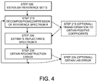
Figure 4 illustrates a flow chart of the steps of an implementation of the disclosure. -
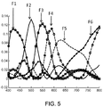
Figure 5 illustrates the spectrums for a set of filters from an implementation of the disclosure. -
Figure 6 illustrates a comparison of the reference spectrum S and the reconstructed spectrum R. -
Figure 7 illustrates the Delta E CIE LAB error for an example reconstructed spectrum R. -
Figure 8 illustrates a color comparison of the reference spectrum S and the reconstructed spectrum R. -
Figure 9 illustrates an example implementation with validation unit including a set of six unique sources and six receivers for illuminating a document. -
Figure 10 illustrates an example implementation of the disclosure with a validation unit including three unique sources and receivers showing both light reflected on and light transmitted through a document. -
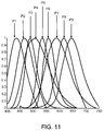
Figure 11 illustrates a set of spectrum for an example group of nine phosphors used to create light emitting diodes. -
Figure 12 illustrates reflectance from and transmission through an item of currency according to an implementation. -
Figure 13 illustrates an implementation utilizing at least one specified physical filter coupled to a broadband source. -
Figure 14 illustrates an implementation utilizing at least one specified physical filter coupled to at least one receiver. -
Figure 15 illustrates an example of a filter apparatus. -
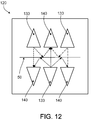
Figure 16 illustrates an example of a sensor array. -
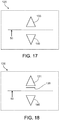
Figure 17 illustrates an example of a sensing unit. -
Figure 18 illustrates an example of a sensing unit. - Various aspects of the invention are set forth in the claims.
- The disclosure relates to classifying items of currency. For the purposes of the disclosure, classification of currency items includes, but is not limited to, recognition, verification, validation, authentication and determination of denomination.
- In an implementation, a
currency validation system 10 includes avalidation unit 100 for classifying currency items (not shown) inserted therein. In some implementations,validation unit 100 includes asensing unit 120 comprised of at least onesource 130 and at least onereceiver 140. For example, sensingunit 120 can be arranged to include at least one light emitting diode (LED) 130 and at least onereceiver 140 for receiving light emitted from theLED 130. In some implementations,LED 130 emits light in at least one of the visible or the non-visible light spectrum. - In some implementations, a method is used to determine the number of light sources to be implemented in
document handling unit 10. More particularly, a set of reference spectrum associated with at least onecurrency item 50, or a portion thereof, can be used as inputs to a dimension reduction technique. For example, the reference set of spectrum S can be used as inputs to a dimension reduction technique to achieve a form of data compression of the reference spectrum S. In some implementations the reference set of spectrum S is represented by a matrix of spectrum responses. In other implementations, a series of spectrum of patches (e.g., Munsell Patches or Pantone Patches) scanned in increments (e.g., every 1 nm) can be used to form the reference set S. - In some implementations, a method is used to simulate a reference spectrum, for example to reconstruct the spectrum of a non-authentic document such as a forgery or copy.
- Once reference set S has been established, for example by at least one of the methods described herein, a data reduction technique can be used to reduce the amount of data used to estimate the entire set of original spectrum S. Examples of data reduction techniques (or dimension reduction techniques) include, but are not limited to Principle Component Analysis (PCA), non-negative matrix factorization (NMF), or dimension selection algorithms. In some implementations, the entire reference set S (or any subset thereof) can be used for classification.
- In some implementations, a Munsell set of spectra (scanned every 1 nm) is used as inputs to a data reduction technique (or data compression technique). For example, 1269 Munsell patches (i.e., a Munsell set), each scanned every 1nm wavelength from 380nm - 800nm, can be used as inputs to the PCA in order to find the most relevant PCA axes. More specifically, using PCA as a tool, the Munsell set is transformed from an original multidimensional space to the PCA space where each axis of the PCA space is a linear combination of all the variables (i.e., a function) from the original space. Using this technique, it can be determined that the first few axis of the PCA space explain most of the variance in the original data set (e.g., reference set or Munsell set). One of the results of using the PCA transformation is that the weights associated with the newly combined linear combinations (i.e., functions) of the original reference set S can be both negative and non-negative. In order to produce a non-negative result from applying PCA to the original reference set S, a transformation is needed to establish a new set of filters (i.e., functions) in which all the coefficients are positive.
- Non-negative matrix factorization (NMF) is an example of another dimension reduction technique which can be used to find a new space (i.e., filter space) with positive coefficients so that the approximating functions are positive and therefore have a physical meaning.
- When using non-negative matrix factorization, the variables can be obtained where the coefficients of the functions are the weights obtained by the non-negative matrix factorization. These functions can physically be built as filters (or sources) because they have a physical meaning in the sense that all weights are positive. Many versions of NMF exist, for example, NMF with different constraints, for example, finding orthogonal basis.
- In some implementations, the reference set of spectrum S is used to establish a set of functions F. More specifically, the PCA axis are constructed using the reference set S, and then the principle components are transformed into another space (i.e., function space) using the constraint that the new coefficients are all positive. Referring to
Figure 4 , a reference set of spectrum S is established instep 200. Instep 210, the spectrum compression (i.e., dimension reduction) C into the function space is given by the following equation:
- The performance of the functions F can be evaluated (step 220) by inversing the operation and estimating the reflectance spectrum R (in the reconstruction space) using, for example, the pseudo-inverse operator given by the following equations:


- In some implementations, the error of the reconstruction of the reflectance spectrum R is obtained, for example, by using the Frobenius norm (step 230). In other implementations the error of the color reconstruction (step 235) is obtained using the Delta E CIE LAB error between the LAB values, of the real (or reference) spectrum S and the reconstructed spectrum R. Use of the error information allows for a comparison of performance in reconstructing the reference spectrum S so that the number of functions in function set F can be determined based on a desired level of performance (or acceptable error). For example, predetermined thresholds or acceptable ranges of error (e.g. Delta E CIE LAB error or Frobenius norm) can be established and the number of functions within function set F can be varied in order to determine the number of functions needed to satisfy the predetermined thresholds for error performance
- In some implementations, a reference set of spectrum S is decomposed using a dimension reduction technique (e.g., PCA) and represented by the following singular value decomposition:

- In
equation 4, F is a set of eigenvectors (i.e., functions). The number of eigenvectors (i.e., functions) can be established in relation to a desired level of performance in reconstructing the reference set of spectrum S. For example, F can be a set of 6 eigenvectors (i.e., functions), but any other number of eigenvectors can be used without varying in scope from the present disclosure. In other implementations, an initial number of functions in set F can be selected and the results obtained fromstep 230 and/or step 235 can be used to determine if more or less functions in set F are needed (as shown inFigure 4 ). In some implementations, at least one function can be established for use in combination with a plurality of standard LED's or sources (e.g., red, blue, green, and infrared). In such an implementation, a set of standard LED's (e.g., red, blue, and green) are arranged invalidation apparatus 10 with at least onespecified source 133 determined from the decomposition of reference set S as shown inFigure 11 . In other implementations, at least onebroadband source 131, having a specifiedphysical filter 135 associated therewith, is arranged with a plurality of standard LED's. - For the purposes of the disclosure, the term broadband source refers to a source with an emission spectrum having relatively constant intensity across either the full spectrum (e.g., visible and/or non-visible) or relatively constant intensity across a very broad range of wavelengths.
- Following the decomposition of the reference set of spectrum S (e.g., using PCA), a constrained linear transformation of F is performed to obtain positive functions. More specifically it can be desirable to find a set of new functions F given by the following equation:

-
Figure 5 shows an example of the results from the above method when the set of functions F contains 6 functions (F1 thru F6).Figure 6 shows a comparison of the reference set of spectrum S and the reconstructed spectrum R using 6 functions.Figure 7 shows the Delta E CIE LAB error for each patch in the reference set based on the set of functions F having 6 functions.Figure 8 shows a comparison of the reference set of spectrum S and the reconstructed spectrum R in the color space, using 6 functions in function set F. - In some implementations, the
sources 133 are specified using the disclosed method for establishing a set of functions F such that eachspecified source 133 have an emission spectrum similar to one of the functions in set F. More particularly, the material used to manufacture certain sources (e.g., the phosphor in LEDs) can be selected and/or mixed in a predetermined manner in order to obtain performance characteristics similar to the functions of function set F. For example, there can be a set of phosphors P used to construct LEDs each having a specific spectrum. In other implementations, the set of phosphors P can be a component of an excitation element coupled to an emitting source. From previous examples, a function set F has a respective spectrum as shown infigure 5 . Therefore given the set of functions F = F1, F2, F3, F4, F5, F6 an approximation of each function can be made using a mix of phosphor spectrum by forming a non negative least square problem. If we use, for example 9 phosphors {P = P1, P2, P3, P4, P5, P6, P7, P8, P9}, a plurality (for example 6) of specifiedsources 133 can be established. For each F, a matrix A can be found that minimizes:
- Matrix A provides the quantity of each phosphor present in each
specified source 133 as shown below:
- Using the example of Matrix A, a group of 6 specified
sources 133 can be constructed with a mix of phosphors P1 thru P9. For example specifiedsource # 1 could be constructed with combination of phosphors {P1F1;P1F1; P3F1; P4F1; P5F1; P6F1; P7F1; P8F1; P9F1} such that it approximates function F1. In some implementations the actual mix of phosphors can be adjusted to account for losses and/or absorptions that may occur due to the combination of multiple phosphors such that the emission spectrum of specifiedsource 133, having a mixture of phosphors, is similar to an approximating function used to reconstruct the original reference spectrum S. - Similarly any number of specified sources can be created using a predetermined group of functions F established by the method of the disclosure and a group of source manufacturing materials. It is contemplated that other types of sources, and thus other types of materials, can be used to construct specified
source 133 without varying in scope from the present disclosure. For example, materials used for organic LEDs, fluorescent light tubes, or any other source commonly know to those skilled in the arts can be used to create a set of specifiedsources 133. - In some implementations, the
currency validation apparatus 10 comprises a set of specifiedsources 133, each corresponding to an approximating function for estimating the reflectance spectrum R from the set of reference spectrum S. For example, avalidation apparatus 10 includes 6 specifiedsources 133 which have been constructed such that each one has an emission spectrum similar to the approximating functions F established by approximating the reflectance spectrum R from the set of reference spectrum S. The number of specifiedsources 133 used invalidation apparatus 10 can be more or less than the six specified sources disclosed in the foregoing example. - In practice, the number of
sources 133 used invalidation apparatus 10 can be selected based on the desired performance (e.g., Delta E CIE LAB error or Frobenius norm) and/or certain constraints (e.g., cost, acceptance rate, or rejection rate). In some implementations,validation apparatus 10 is arranged to include a plurality of standard LED's 180 (e.g., red, green, and blue; or red, green, blue and infrared), at least onespecified source 190 and at least onereceiver 140 for receiving light fromsources source 190 can be retrofit into an existing validation apparatus 10 (i.e., already having a plurality of standard LED's) such that performance ofvalidation apparatus 10 is enhanced (e.g., by improving Delta E CIE LAB error). More particularly, specifiedsource 190 can be configured such that its' spectral emission is similar to that of at least one currency item to be classified byvalidation apparatus 10. - In some implementations the reference set S used to determine the characteristics of the specified sources is different from other reference sets in order to optimize the performance of
validation apparatus 10. - In other implementations,
validation apparatus 10 includes abroadband source 180 with a generally broad emission spectrum such that a plurality of specified filters derived from function set F are included inapparatus 10 such that reconstruction of the original spectrum S can be accomplished. The set of functions F is derived such that the relationships ofequations 1 thru 5 are satisfied. In implementations whereby physical filters are coupled with a broadband source (or plurality of broadband sources) 180 allows for flexibility in design such thatapparatus 10 can be tuned for performance to satisfy any predetermined criteria (e.g., Delta E CIE LAB Error or Frobenius norm). - In some implementations, the at least one function established from the methods of the disclosure, result in a particular spectrum shape. For example, in an implementation of 6 physical filters (or sources or mixed light) there can be at least one filter having a spectral shape having a large band and at least two lobes as shown in
Figure 5 (e.g., F2). In some configurations a filter can have a large band higher than 35nm (e.g., roughly 50nm or more at half of the peak intensity). The number of filters implemented can vary. The corresponding changes in spectral shapes for each resulting filter are not limitations and, therefore, variation is within the scope of the present disclosure. - Classification of currency items can be accomplished in either the function space (i.e., using the direct data obtained from the at least one receiver) or in the reconstructed spectrum space (i.e., using the approximation functions to reconstruct the original spectrum). In an implementation for which classification occurs in the function space, classification of an inserted item can be made using traditional classification techniques (e.g., Malahanobis Distance, Feature Vector Selection, or Support Vector Machine). In an implementation for which classification occurs in the reconstructed space, the set of reconstructed reflectance measurements can be used with metamerism theory to classify at least one
item 50. Classification in the reconstructed space can include the comparison of a reference response (for example stored in memory) with the reconstructed response of an inserted item such that a determination of a metameric match can be made.U.S. Provisional Patent Application Serial No. 61/137,386 WO 2010/014705 ) discloses various techniques for classifying an item of currency using metameric theory and various classification techniques and algorithms. - In some implementations, a
broadband source 180 is coupled with a plurality ofphysical filters 195 each having a spectral transmission spectrum similar an approximating function from the disclosed method. For example, abroadband source 180 can be coupled to amoveable filter apparatus 300 as shown inFigure 15 . More specifically,movable filter apparatus 300 is comprised of a plurality of physical filters (F1, F2, F3...) and is selectively movable between a plurality of positions relative tobroadband source 180.Figure 15 showsbroadband source 180 coupled to filterapparatus 300 at position Z1 whereby filter F1 is positioned for transmitting filtered light frombroadband source 180. Similarly,filter apparatus 300 can be moved such that any one of the plurality of filters can be positioned for transmitting filtered light frombroadband source 180 there through. - For example,
filter apparatus 300 can be implemented as a generally curved housing containing a plurality of filters as shown inFigure 15 . In some implementations filterapparatus 300 can be slidingly moved between a plurality ofpositions 1 thru 3 (e.g., having 3 filters) so as to couple a particular filter withbroadband source 180 for transmission of light emitted there through. - In other implementations, the
document validation apparatus 10 can include a plurality of specified sources coupled to a light pipe, and an integrating sensor. In such an exemplary implementation, each of the plurality of specified sources can be controlled using pulse width modulation in order to manage the amount of light emitted from each source into the light pipe. Such an implementation allows for the mixing of a set of specified sources similar to previously disclosed implementations of mixing phosphors or other substance used as a component in an excitation element to produce an overall emitted spectrum from the light pipe similar to an approximating function for reconstructing the reference spectrum R. - In an implementation,
document validation apparatus 10 can include at lease one broadband source and aCCD sensor 500 having a plurality of specified physical filters (or excitation elements) associated therewith (as shown inFigure 16 ). In an exemplary implementation, light emitted from a broadband source is transmitted through asensor array 550 coupled tosensor 500 and therefore received byCCD sensor 500. Each pixel in the CCD sensor can be estimated using, for example, a Bayer algorithm to find the "mixed" light received so as to be comparable to an approximating function as described herein.Figure 16 shows an exemplary implementation of such a configuration. Other configurations offilter array 550 as shown are contemplated where a different distribution of specified filters are therein arranged and therefore are not outside the scope of the disclosure. - In an implementation as in
Figure 16 , the center of the pixel can be calculated using a Bayer type algorithm so that the actual light received at a particular pixel ofsensor 500 can be a combination of the surrounding filters offilter array 550 in order to sense a response similar to an approximating function for reconstructing the original reference spectrum S. - Other implementations, including variations and modifications, are within the scope of the claims.
Claims (15)
- A validation apparatus comprising:at least three specified light sources (133) for illuminating an item of currency (50), each of the at least three specified light sources (133) having an emission spectrum similar to an approximating function for reconstructing a predetermined reference set of spectrum;at least one receiver (140) for receiving light emitting from the at least three specified light sources (133);a transportation unit for transporting the item of currency (50) within the validation apparatus;wherein the light received by the at least one receiver (140) is at least one of light reflected by or light transmitted through the item of currency (50);wherein the at least three specified light sources (133) are constructed using at least one predetermined phosphor, wherein each phosphor corresponds to a particular emission spectrum; andwherein the at least three specified light sources (133) are constructed using a mixture of a plurality of predetermined phosphors such that the emission spectrum of each of the at least three specified light sources (133) is similar to an approximating function for reconstructing the reference spectrum.
- A validation apparatus according to claim 1 wherein the at least three specified sources (133) collectively emit light in the visible and non-visible light spectrum.
- A validation apparatus according to claim 1 wherein the at least three specified sources (133) emit light in the visible light spectrum or
wherein the at least three specified sources (133) emit light in the non-visible light spectrum. - A validation apparatus according to one of the preceding claims wherein each of the at least three specified sources (133) are energized in a predetermined manner.
- A validation apparatus according to one of the preceding claims wherein the transportation unit is configured to include a plurality of transportation subunits arranged to form a continuous transportation path.
- A validation apparatus according to one of the preceding claims wherein the transportation unit is arranged to transport the item of currency (50) past the at least three specified sources (133) and the at least one receiver (140).
- A validation apparatus according to one of the preceding claims arranged to classify the item of currency (50) using the received light from each of the at least three specified sources (133).
- A validation apparatus according to claim 7 arranged to perform classification of the currency item (50) in a function space or in a reconstruction space.
- A validation apparatus according to one of the preceding claims further comprising a processor.
- A validation apparatus according to claim 7 or 8 wherein a processor is configured for classifying the currency item (50).
- A validation apparatus according to claim 9 or 10 further comprising a memory unit operatively coupled to the processor.
- A validation apparatus according to claim 11 wherein the memory unit is configured to store information used to classify the item of currency (50).
- A validation apparatus according to one of the preceding claims wherein the at least three specified light sources (133) are organic LEDs.
- A validation apparatus according to one of the preceding claims wherein at least one of the at least three specified light sources (133) has an emission spectrum having a band of at least 50 nanometers.
- A validation apparatus according to claim 14 wherein the at least one of the at least three specified sources (133) has an emission spectrum having a large band and at least two lobes.
Priority Applications (2)
| Application Number | Priority Date | Filing Date | Title |
|---|---|---|---|
| EP11188954.9A EP2426650B1 (en) | 2009-04-08 | 2010-04-07 | Characterizing items of currency |
| EP11188955.6A EP2420979B1 (en) | 2009-04-08 | 2010-04-07 | Characterizing items of currency |
Applications Claiming Priority (2)
| Application Number | Priority Date | Filing Date | Title |
|---|---|---|---|
| US16772909P | 2009-04-08 | 2009-04-08 | |
| PCT/US2010/030277 WO2010118160A1 (en) | 2009-04-08 | 2010-04-07 | Characterizing items of currency |
Related Child Applications (6)
| Application Number | Title | Priority Date | Filing Date |
|---|---|---|---|
| EP11188954.9A Division-Into EP2426650B1 (en) | 2009-04-08 | 2010-04-07 | Characterizing items of currency |
| EP11188954.9A Division EP2426650B1 (en) | 2009-04-08 | 2010-04-07 | Characterizing items of currency |
| EP11188955.6A Division-Into EP2420979B1 (en) | 2009-04-08 | 2010-04-07 | Characterizing items of currency |
| EP11188955.6A Division EP2420979B1 (en) | 2009-04-08 | 2010-04-07 | Characterizing items of currency |
| EP11188955.6 Division-Into | 2011-11-14 | ||
| EP11188954.9 Division-Into | 2011-11-14 |
Publications (2)
| Publication Number | Publication Date |
|---|---|
| EP2417583A1 EP2417583A1 (en) | 2012-02-15 |
| EP2417583B1 true EP2417583B1 (en) | 2016-03-30 |
Family
ID=42288615
Family Applications (3)
| Application Number | Title | Priority Date | Filing Date |
|---|---|---|---|
| EP11188955.6A Not-in-force EP2420979B1 (en) | 2009-04-08 | 2010-04-07 | Characterizing items of currency |
| EP10719137.1A Not-in-force EP2417583B1 (en) | 2009-04-08 | 2010-04-07 | Characterizing items of currency |
| EP11188954.9A Not-in-force EP2426650B1 (en) | 2009-04-08 | 2010-04-07 | Characterizing items of currency |
Family Applications Before (1)
| Application Number | Title | Priority Date | Filing Date |
|---|---|---|---|
| EP11188955.6A Not-in-force EP2420979B1 (en) | 2009-04-08 | 2010-04-07 | Characterizing items of currency |
Family Applications After (1)
| Application Number | Title | Priority Date | Filing Date |
|---|---|---|---|
| EP11188954.9A Not-in-force EP2426650B1 (en) | 2009-04-08 | 2010-04-07 | Characterizing items of currency |
Country Status (7)
| Country | Link |
|---|---|
| US (1) | US8739954B2 (en) |
| EP (3) | EP2420979B1 (en) |
| JP (1) | JP5588499B2 (en) |
| CN (1) | CN102439635B (en) |
| AU (1) | AU2010234450B2 (en) |
| CA (1) | CA2757924A1 (en) |
| WO (1) | WO2010118160A1 (en) |
Families Citing this family (6)
| Publication number | Priority date | Publication date | Assignee | Title |
|---|---|---|---|---|
| GB201008177D0 (en) * | 2010-05-17 | 2010-06-30 | Scan Coin Ab | Coin discriminators |
| DE102012014958A1 (en) * | 2012-07-30 | 2014-02-13 | Crane Payment Solutions Gmbh | Coin and method for checking the coin |
| CN103646458B (en) * | 2013-12-23 | 2015-10-28 | 华中科技大学 | The method of the principal component analysis identification note true and false |
| DE102014101307A1 (en) * | 2014-02-03 | 2015-08-06 | Osram Opto Semiconductors Gmbh | Coding method for data compression of power spectra of an optoelectronic device and decoding method |
| CN104537756B (en) * | 2015-01-22 | 2018-04-20 | 广州广电运通金融电子股份有限公司 | A kind of assortment of bank note discrimination method and device based on Lab color spaces |
| JP6760663B2 (en) * | 2018-07-03 | 2020-09-23 | フェムトディプロイメンツ株式会社 | Sample analyzer and sample analysis program |
Family Cites Families (17)
| Publication number | Priority date | Publication date | Assignee | Title |
|---|---|---|---|---|
| JPH0666075B2 (en) * | 1985-10-16 | 1994-08-24 | 富士通株式会社 | Paper discrimination processing device |
| JPH0644437A (en) * | 1992-07-24 | 1994-02-18 | Oki Electric Ind Co Ltd | Recognizing device for paper sheet etc |
| US5632367A (en) | 1995-01-23 | 1997-05-27 | Mars, Incorporated | Validation housing for a bill validator made by a two shot molding process |
| US6040584A (en) * | 1998-05-22 | 2000-03-21 | Mti Corporation | Method and for system for detecting damaged bills |
| DE10007887A1 (en) * | 2000-02-21 | 2001-08-23 | Giesecke & Devrient Gmbh | Method and device for checking the authenticity of printed objects |
| JP3836302B2 (en) | 2000-06-09 | 2006-10-25 | 帝眞貿易株式会社 | Identification method and identification apparatus using identification marks |
| JP4266495B2 (en) * | 2000-06-12 | 2009-05-20 | グローリー株式会社 | Banknote handling machine |
| JP3518518B2 (en) * | 2001-03-05 | 2004-04-12 | 松下電器産業株式会社 | Banknote recognition device |
| WO2003015037A2 (en) | 2001-08-06 | 2003-02-20 | Mars Incorporated | Document validator subassembly |
| DE10160578A1 (en) * | 2001-12-10 | 2004-02-12 | Giesecke & Devrient Gmbh | Method and device for checking the authenticity of sheet material |
| CN101329784B (en) * | 2002-12-27 | 2011-02-09 | 日本金钱机械株式会社 | Optical detection device for detecting optical characteristics of securities |
| JP4334910B2 (en) * | 2003-05-28 | 2009-09-30 | ローレル精機株式会社 | Banknote image detection device |
| JP4334911B2 (en) * | 2003-05-28 | 2009-09-30 | ローレル精機株式会社 | Banknote image detection device |
| JP2005072129A (en) | 2003-08-21 | 2005-03-17 | Nec Lighting Ltd | Visible light emitting device, its manufacturing method, and display |
| KR20070086572A (en) * | 2004-11-23 | 2007-08-27 | 오렐 퓌슬리 지혀하이츠드럭 에이지 | Security document with light source and light processing device |
| US7795600B2 (en) * | 2006-03-24 | 2010-09-14 | Goldeneye, Inc. | Wavelength conversion chip for use with light emitting diodes and method for making same |
| JP4645536B2 (en) * | 2006-06-20 | 2011-03-09 | 富士電機リテイルシステムズ株式会社 | Paper sheet identification device |
-
2010
- 2010-04-07 US US13/263,463 patent/US8739954B2/en not_active Expired - Fee Related
- 2010-04-07 JP JP2012504833A patent/JP5588499B2/en not_active Expired - Fee Related
- 2010-04-07 CN CN201080022325.XA patent/CN102439635B/en not_active Expired - Fee Related
- 2010-04-07 EP EP11188955.6A patent/EP2420979B1/en not_active Not-in-force
- 2010-04-07 CA CA2757924A patent/CA2757924A1/en not_active Abandoned
- 2010-04-07 WO PCT/US2010/030277 patent/WO2010118160A1/en not_active Ceased
- 2010-04-07 EP EP10719137.1A patent/EP2417583B1/en not_active Not-in-force
- 2010-04-07 EP EP11188954.9A patent/EP2426650B1/en not_active Not-in-force
- 2010-04-07 AU AU2010234450A patent/AU2010234450B2/en not_active Ceased
Also Published As
| Publication number | Publication date |
|---|---|
| JP2012523628A (en) | 2012-10-04 |
| AU2010234450A1 (en) | 2011-11-03 |
| AU2010234450B2 (en) | 2014-06-26 |
| CN102439635A (en) | 2012-05-02 |
| EP2417583A1 (en) | 2012-02-15 |
| EP2426650A1 (en) | 2012-03-07 |
| CN102439635B (en) | 2014-12-10 |
| CA2757924A1 (en) | 2010-10-14 |
| WO2010118160A1 (en) | 2010-10-14 |
| EP2426650B1 (en) | 2015-12-02 |
| US8739954B2 (en) | 2014-06-03 |
| US20120118698A1 (en) | 2012-05-17 |
| JP5588499B2 (en) | 2014-09-10 |
| EP2420979B1 (en) | 2015-12-02 |
| EP2420979A1 (en) | 2012-02-22 |
Similar Documents
| Publication | Publication Date | Title |
|---|---|---|
| EP2420979B1 (en) | Characterizing items of currency | |
| US9514591B2 (en) | Paper-sheet recognition apparatus, paper-sheet processing apparatus, and paper-sheet recognition method | |
| US20050100204A1 (en) | Method and apparatus for detecting fluorescent particles contained in a substrate | |
| US20120072176A1 (en) | System and method of evaluating an object using electromagnetic energy | |
| CN102598023B (en) | Authentication apparatus for value documents | |
| CN102138165B (en) | Classifying and discriminating an item of currency based on the item's spectral response | |
| CN104094323B (en) | For characterizing the apparatus and method of currency item | |
| CN111009070B (en) | Banknote imaging | |
| Coombs et al. | Advanced verification methods for OVI security ink | |
| EP2304650B1 (en) | Currency discrimination | |
| MXPA98010172A (en) | Validator of bancar documents | |
| Kamshilin et al. | New Approach for Fast and Accurate Color‐pattern Recognition |
Legal Events
| Date | Code | Title | Description |
|---|---|---|---|
| PUAI | Public reference made under article 153(3) epc to a published international application that has entered the european phase |
Free format text: ORIGINAL CODE: 0009012 |
|
| 17P | Request for examination filed |
Effective date: 20111025 |
|
| AK | Designated contracting states |
Kind code of ref document: A1 Designated state(s): AT BE BG CH CY CZ DE DK EE ES FI FR GB GR HR HU IE IS IT LI LT LU LV MC MK MT NL NO PL PT RO SE SI SK SM TR |
|
| DAX | Request for extension of the european patent (deleted) | ||
| RAP1 | Party data changed (applicant data changed or rights of an application transferred) |
Owner name: MEI, INC. |
|
| 17Q | First examination report despatched |
Effective date: 20150423 |
|
| GRAP | Despatch of communication of intention to grant a patent |
Free format text: ORIGINAL CODE: EPIDOSNIGR1 |
|
| INTG | Intention to grant announced |
Effective date: 20151204 |
|
| RAP1 | Party data changed (applicant data changed or rights of an application transferred) |
Owner name: CRANE PAYMENT INNOVATIONS, INC. |
|
| GRAS | Grant fee paid |
Free format text: ORIGINAL CODE: EPIDOSNIGR3 |
|
| GRAA | (expected) grant |
Free format text: ORIGINAL CODE: 0009210 |
|
| AK | Designated contracting states |
Kind code of ref document: B1 Designated state(s): AT BE BG CH CY CZ DE DK EE ES FI FR GB GR HR HU IE IS IT LI LT LU LV MC MK MT NL NO PL PT RO SE SI SK SM TR |
|
| REG | Reference to a national code |
Ref country code: GB Ref legal event code: FG4D |
|
| REG | Reference to a national code |
Ref country code: CH Ref legal event code: EP |
|
| REG | Reference to a national code |
Ref country code: AT Ref legal event code: REF Ref document number: 786098 Country of ref document: AT Kind code of ref document: T Effective date: 20160415 |
|
| REG | Reference to a national code |
Ref country code: IE Ref legal event code: FG4D |
|
| REG | Reference to a national code |
Ref country code: DE Ref legal event code: R096 Ref document number: 602010031690 Country of ref document: DE |
|
| REG | Reference to a national code |
Ref country code: LT Ref legal event code: MG4D |
|
| PG25 | Lapsed in a contracting state [announced via postgrant information from national office to epo] |
Ref country code: FI Free format text: LAPSE BECAUSE OF FAILURE TO SUBMIT A TRANSLATION OF THE DESCRIPTION OR TO PAY THE FEE WITHIN THE PRESCRIBED TIME-LIMIT Effective date: 20160330 Ref country code: HR Free format text: LAPSE BECAUSE OF FAILURE TO SUBMIT A TRANSLATION OF THE DESCRIPTION OR TO PAY THE FEE WITHIN THE PRESCRIBED TIME-LIMIT Effective date: 20160330 Ref country code: GR Free format text: LAPSE BECAUSE OF FAILURE TO SUBMIT A TRANSLATION OF THE DESCRIPTION OR TO PAY THE FEE WITHIN THE PRESCRIBED TIME-LIMIT Effective date: 20160701 Ref country code: NO Free format text: LAPSE BECAUSE OF FAILURE TO SUBMIT A TRANSLATION OF THE DESCRIPTION OR TO PAY THE FEE WITHIN THE PRESCRIBED TIME-LIMIT Effective date: 20160630 |
|
| REG | Reference to a national code |
Ref country code: NL Ref legal event code: MP Effective date: 20160330 |
|
| REG | Reference to a national code |
Ref country code: AT Ref legal event code: MK05 Ref document number: 786098 Country of ref document: AT Kind code of ref document: T Effective date: 20160330 |
|
| PG25 | Lapsed in a contracting state [announced via postgrant information from national office to epo] |
Ref country code: SE Free format text: LAPSE BECAUSE OF FAILURE TO SUBMIT A TRANSLATION OF THE DESCRIPTION OR TO PAY THE FEE WITHIN THE PRESCRIBED TIME-LIMIT Effective date: 20160330 Ref country code: LT Free format text: LAPSE BECAUSE OF FAILURE TO SUBMIT A TRANSLATION OF THE DESCRIPTION OR TO PAY THE FEE WITHIN THE PRESCRIBED TIME-LIMIT Effective date: 20160330 Ref country code: BE Free format text: LAPSE BECAUSE OF NON-PAYMENT OF DUE FEES Effective date: 20160430 Ref country code: LV Free format text: LAPSE BECAUSE OF FAILURE TO SUBMIT A TRANSLATION OF THE DESCRIPTION OR TO PAY THE FEE WITHIN THE PRESCRIBED TIME-LIMIT Effective date: 20160330 |
|
| PG25 | Lapsed in a contracting state [announced via postgrant information from national office to epo] |
Ref country code: NL Free format text: LAPSE BECAUSE OF FAILURE TO SUBMIT A TRANSLATION OF THE DESCRIPTION OR TO PAY THE FEE WITHIN THE PRESCRIBED TIME-LIMIT Effective date: 20160330 |
|
| PG25 | Lapsed in a contracting state [announced via postgrant information from national office to epo] |
Ref country code: EE Free format text: LAPSE BECAUSE OF FAILURE TO SUBMIT A TRANSLATION OF THE DESCRIPTION OR TO PAY THE FEE WITHIN THE PRESCRIBED TIME-LIMIT Effective date: 20160330 Ref country code: IS Free format text: LAPSE BECAUSE OF FAILURE TO SUBMIT A TRANSLATION OF THE DESCRIPTION OR TO PAY THE FEE WITHIN THE PRESCRIBED TIME-LIMIT Effective date: 20160730 Ref country code: PL Free format text: LAPSE BECAUSE OF FAILURE TO SUBMIT A TRANSLATION OF THE DESCRIPTION OR TO PAY THE FEE WITHIN THE PRESCRIBED TIME-LIMIT Effective date: 20160330 |
|
| PG25 | Lapsed in a contracting state [announced via postgrant information from national office to epo] |
Ref country code: CZ Free format text: LAPSE BECAUSE OF FAILURE TO SUBMIT A TRANSLATION OF THE DESCRIPTION OR TO PAY THE FEE WITHIN THE PRESCRIBED TIME-LIMIT Effective date: 20160330 Ref country code: RO Free format text: LAPSE BECAUSE OF FAILURE TO SUBMIT A TRANSLATION OF THE DESCRIPTION OR TO PAY THE FEE WITHIN THE PRESCRIBED TIME-LIMIT Effective date: 20160330 Ref country code: PT Free format text: LAPSE BECAUSE OF FAILURE TO SUBMIT A TRANSLATION OF THE DESCRIPTION OR TO PAY THE FEE WITHIN THE PRESCRIBED TIME-LIMIT Effective date: 20160801 Ref country code: SM Free format text: LAPSE BECAUSE OF FAILURE TO SUBMIT A TRANSLATION OF THE DESCRIPTION OR TO PAY THE FEE WITHIN THE PRESCRIBED TIME-LIMIT Effective date: 20160330 Ref country code: SK Free format text: LAPSE BECAUSE OF FAILURE TO SUBMIT A TRANSLATION OF THE DESCRIPTION OR TO PAY THE FEE WITHIN THE PRESCRIBED TIME-LIMIT Effective date: 20160330 Ref country code: ES Free format text: LAPSE BECAUSE OF FAILURE TO SUBMIT A TRANSLATION OF THE DESCRIPTION OR TO PAY THE FEE WITHIN THE PRESCRIBED TIME-LIMIT Effective date: 20160330 Ref country code: AT Free format text: LAPSE BECAUSE OF FAILURE TO SUBMIT A TRANSLATION OF THE DESCRIPTION OR TO PAY THE FEE WITHIN THE PRESCRIBED TIME-LIMIT Effective date: 20160330 |
|
| REG | Reference to a national code |
Ref country code: CH Ref legal event code: PL |
|
| PG25 | Lapsed in a contracting state [announced via postgrant information from national office to epo] |
Ref country code: IT Free format text: LAPSE BECAUSE OF FAILURE TO SUBMIT A TRANSLATION OF THE DESCRIPTION OR TO PAY THE FEE WITHIN THE PRESCRIBED TIME-LIMIT Effective date: 20160330 Ref country code: BE Free format text: LAPSE BECAUSE OF FAILURE TO SUBMIT A TRANSLATION OF THE DESCRIPTION OR TO PAY THE FEE WITHIN THE PRESCRIBED TIME-LIMIT Effective date: 20160330 |
|
| REG | Reference to a national code |
Ref country code: DE Ref legal event code: R097 Ref document number: 602010031690 Country of ref document: DE |
|
| REG | Reference to a national code |
Ref country code: IE Ref legal event code: MM4A |
|
| PG25 | Lapsed in a contracting state [announced via postgrant information from national office to epo] |
Ref country code: LI Free format text: LAPSE BECAUSE OF NON-PAYMENT OF DUE FEES Effective date: 20160430 Ref country code: CH Free format text: LAPSE BECAUSE OF NON-PAYMENT OF DUE FEES Effective date: 20160430 Ref country code: DK Free format text: LAPSE BECAUSE OF FAILURE TO SUBMIT A TRANSLATION OF THE DESCRIPTION OR TO PAY THE FEE WITHIN THE PRESCRIBED TIME-LIMIT Effective date: 20160330 |
|
| PLBE | No opposition filed within time limit |
Free format text: ORIGINAL CODE: 0009261 |
|
| STAA | Information on the status of an ep patent application or granted ep patent |
Free format text: STATUS: NO OPPOSITION FILED WITHIN TIME LIMIT |
|
| REG | Reference to a national code |
Ref country code: FR Ref legal event code: ST Effective date: 20170201 |
|
| 26N | No opposition filed |
Effective date: 20170103 |
|
| PG25 | Lapsed in a contracting state [announced via postgrant information from national office to epo] |
Ref country code: FR Free format text: LAPSE BECAUSE OF NON-PAYMENT OF DUE FEES Effective date: 20160530 |
|
| PG25 | Lapsed in a contracting state [announced via postgrant information from national office to epo] |
Ref country code: IE Free format text: LAPSE BECAUSE OF NON-PAYMENT OF DUE FEES Effective date: 20160407 Ref country code: SI Free format text: LAPSE BECAUSE OF FAILURE TO SUBMIT A TRANSLATION OF THE DESCRIPTION OR TO PAY THE FEE WITHIN THE PRESCRIBED TIME-LIMIT Effective date: 20160330 |
|
| PGFP | Annual fee paid to national office [announced via postgrant information from national office to epo] |
Ref country code: GB Payment date: 20170405 Year of fee payment: 8 Ref country code: DE Payment date: 20170404 Year of fee payment: 8 |
|
| PG25 | Lapsed in a contracting state [announced via postgrant information from national office to epo] |
Ref country code: CY Free format text: LAPSE BECAUSE OF FAILURE TO SUBMIT A TRANSLATION OF THE DESCRIPTION OR TO PAY THE FEE WITHIN THE PRESCRIBED TIME-LIMIT Effective date: 20160330 Ref country code: HU Free format text: LAPSE BECAUSE OF FAILURE TO SUBMIT A TRANSLATION OF THE DESCRIPTION OR TO PAY THE FEE WITHIN THE PRESCRIBED TIME-LIMIT; INVALID AB INITIO Effective date: 20100407 |
|
| PG25 | Lapsed in a contracting state [announced via postgrant information from national office to epo] |
Ref country code: MC Free format text: LAPSE BECAUSE OF FAILURE TO SUBMIT A TRANSLATION OF THE DESCRIPTION OR TO PAY THE FEE WITHIN THE PRESCRIBED TIME-LIMIT Effective date: 20160330 Ref country code: TR Free format text: LAPSE BECAUSE OF FAILURE TO SUBMIT A TRANSLATION OF THE DESCRIPTION OR TO PAY THE FEE WITHIN THE PRESCRIBED TIME-LIMIT Effective date: 20160330 Ref country code: MT Free format text: LAPSE BECAUSE OF NON-PAYMENT OF DUE FEES Effective date: 20160430 Ref country code: MK Free format text: LAPSE BECAUSE OF FAILURE TO SUBMIT A TRANSLATION OF THE DESCRIPTION OR TO PAY THE FEE WITHIN THE PRESCRIBED TIME-LIMIT Effective date: 20160330 Ref country code: LU Free format text: LAPSE BECAUSE OF NON-PAYMENT OF DUE FEES Effective date: 20160407 |
|
| PG25 | Lapsed in a contracting state [announced via postgrant information from national office to epo] |
Ref country code: BG Free format text: LAPSE BECAUSE OF FAILURE TO SUBMIT A TRANSLATION OF THE DESCRIPTION OR TO PAY THE FEE WITHIN THE PRESCRIBED TIME-LIMIT Effective date: 20160330 |
|
| REG | Reference to a national code |
Ref country code: DE Ref legal event code: R119 Ref document number: 602010031690 Country of ref document: DE |
|
| GBPC | Gb: european patent ceased through non-payment of renewal fee |
Effective date: 20180407 |
|
| PG25 | Lapsed in a contracting state [announced via postgrant information from national office to epo] |
Ref country code: DE Free format text: LAPSE BECAUSE OF NON-PAYMENT OF DUE FEES Effective date: 20181101 |
|
| PG25 | Lapsed in a contracting state [announced via postgrant information from national office to epo] |
Ref country code: GB Free format text: LAPSE BECAUSE OF NON-PAYMENT OF DUE FEES Effective date: 20180407 |