EP2416566A2 - Method for handling of audio/video signals and corresponding device - Google Patents
Method for handling of audio/video signals and corresponding device Download PDFInfo
- Publication number
- EP2416566A2 EP2416566A2 EP11172897A EP11172897A EP2416566A2 EP 2416566 A2 EP2416566 A2 EP 2416566A2 EP 11172897 A EP11172897 A EP 11172897A EP 11172897 A EP11172897 A EP 11172897A EP 2416566 A2 EP2416566 A2 EP 2416566A2
- Authority
- EP
- European Patent Office
- Prior art keywords
- analog
- audio
- digital
- video
- interface
- Prior art date
- Legal status (The legal status is an assumption and is not a legal conclusion. Google has not performed a legal analysis and makes no representation as to the accuracy of the status listed.)
- Ceased
Links
- 238000000034 method Methods 0.000 title claims abstract description 19
- 238000006243 chemical reaction Methods 0.000 claims description 21
- 238000005457 optimization Methods 0.000 abstract description 4
- 230000006870 function Effects 0.000 description 5
- 238000001514 detection method Methods 0.000 description 2
- 238000004891 communication Methods 0.000 description 1
- 230000002860 competitive effect Effects 0.000 description 1
- 238000000605 extraction Methods 0.000 description 1
- 230000010354 integration Effects 0.000 description 1
- 238000004519 manufacturing process Methods 0.000 description 1
- 238000009877 rendering Methods 0.000 description 1
- 238000005070 sampling Methods 0.000 description 1
- 230000017105 transposition Effects 0.000 description 1
Images


Classifications
-
- H—ELECTRICITY
- H04—ELECTRIC COMMUNICATION TECHNIQUE
- H04N—PICTORIAL COMMUNICATION, e.g. TELEVISION
- H04N5/00—Details of television systems
- H04N5/44—Receiver circuitry for the reception of television signals according to analogue transmission standards
- H04N5/46—Receiver circuitry for the reception of television signals according to analogue transmission standards for receiving on more than one standard at will
-
- H—ELECTRICITY
- H04—ELECTRIC COMMUNICATION TECHNIQUE
- H04N—PICTORIAL COMMUNICATION, e.g. TELEVISION
- H04N21/00—Selective content distribution, e.g. interactive television or video on demand [VOD]
- H04N21/40—Client devices specifically adapted for the reception of or interaction with content, e.g. set-top-box [STB]; Operations thereof
- H04N21/41—Structure of client; Structure of client peripherals
-
- H—ELECTRICITY
- H04—ELECTRIC COMMUNICATION TECHNIQUE
- H04N—PICTORIAL COMMUNICATION, e.g. TELEVISION
- H04N21/00—Selective content distribution, e.g. interactive television or video on demand [VOD]
- H04N21/40—Client devices specifically adapted for the reception of or interaction with content, e.g. set-top-box [STB]; Operations thereof
- H04N21/41—Structure of client; Structure of client peripherals
- H04N21/4104—Peripherals receiving signals from specially adapted client devices
- H04N21/4135—Peripherals receiving signals from specially adapted client devices external recorder
-
- H—ELECTRICITY
- H04—ELECTRIC COMMUNICATION TECHNIQUE
- H04N—PICTORIAL COMMUNICATION, e.g. TELEVISION
- H04N21/00—Selective content distribution, e.g. interactive television or video on demand [VOD]
- H04N21/40—Client devices specifically adapted for the reception of or interaction with content, e.g. set-top-box [STB]; Operations thereof
- H04N21/41—Structure of client; Structure of client peripherals
- H04N21/426—Internal components of the client ; Characteristics thereof
- H04N21/42607—Internal components of the client ; Characteristics thereof for processing the incoming bitstream
-
- H—ELECTRICITY
- H04—ELECTRIC COMMUNICATION TECHNIQUE
- H04N—PICTORIAL COMMUNICATION, e.g. TELEVISION
- H04N5/00—Details of television systems
- H04N5/44—Receiver circuitry for the reception of television signals according to analogue transmission standards
Definitions
- the present invention generally relates to a method and device for handling of audio/video signals originating from a mix of analog and digital sources of audio/video signals.
- the present invention relates to optimization of hardware resources and of wiring needed for the interconnection of various analog and digital sources of audio/video signals.
- Manufacturers of consumer devices for reception and decoding of radio-frequency modulated audio/video signals for rendering of audiovisual services tend to minimize hardware resources of those devices in order to reduce production costs and ensure a competitive market price.
- processing and memory resources are tailored to the strictly needed.
- the present invention aims at alleviating some of the inconveniences of prior art.
- the invention proposes a solution for optimization of the interconnection of analog and digital audio/video devices, that avoids among others the aforementioned drawbacks of prior art solutions.
- 'audio/video' and the abbreviation 'AV' is used in this document to indicate audio, video, or both audio and video.
- the invention proposes a device for reception of digital radio frequency modulated audio/video signals, comprising a digital audio/video output interface, and a tuner comprising an analog to digital convertor, the analog to digital convertor being used for analog to digital conversion of an analog input signal that originates from either of at least two signal sources, the at least two signal sources comprising a front end of the tuner and an analog audio/video input interface, the analog input signal, after having been converted to a digital output signal by the analog to digital conversion, being at the origin of a digital audio/video signal that is output on the digital audio/video interface after further processing by said device.
- the digital audio/video signal finds its source (or 'origin') in for example either an RF modulated DVB-T signal transporting television or radio programmes, or an audio/video signal received from a DVD player via the device's analog AV interface.
- the device further comprises a switch for selection of either one of the at least two signal sources.
- the device further comprises a controller for controlling the switch.
- the controller reduces power consumption of hardware components of the device that are not needed according to the selection of either of said at least two signal sources.
- the device is a Set Top Box for reception of digital radio and television programs.
- the digital audio/video output interface is according to a High-Definition Multi-media Interface.
- the analog audio/video input interface is one of according to a
- the invention also concerns a method for handling of audio/video signals, implemented by a device for reception of radio frequency modulated audio/video signals, the device comprising a digital audio/video output interface, the method comprising a step of selection of a source of audio/video signals for input into an analog to digital convertor for analog to digital conversion of an analog input signal that originates from either of at least two signal sources, the at least two signal sources comprising a front end of a tuner and an analog audio/video input interface, the analog input signal, after having been converted to a digital output signal by the analog to digital conversion, being at the origin of a digital audio/video signal that is output on the digital audio/video output interface after further processing by the device.
- the method comprises a step of controlling the selection through determination of a presence of a analog audio/video signal on the analog audio/video input interface, said controlling determining a connection of one of said at least two signal sources to said analog to digital conversion.
- the method comprises a step of reduction of power consumption of hardware components that are not needed in handling of those of the at least two signal sources that are not a source for the analog to digital conversion.
- FIG. 1 shows prior-art interconnection of analog and digital audio/video devices.
- Digital Terrestrial Television (DTT) Set Top Box (STB) 11 and a DVD player 12 are connected to a digital television 10.
- DTT Digital Terrestrial Television
- STB Set Top Box
- DVD player 12 are connected to a digital television 10.
- DTV 10 is equipped with analog audio/video input interface 1001 and digital video input interface 1002.
- DTT STB 11 is equipped with a digital audio/video output interface 1101 and an analog audio/video input interface 1103 and output interface 1102.
- DVD player 12 is equipped with an analog output interface 1201.
- STB 11 is further connected to an antenna 104.
- RF radio frequency
- the figure shows several prior-art possibilities of interconnection for DVD player 12 to DTV 10; DVD player 12 can either be connected directly to DTV 10 via analog connection 101, or indirectly, via STB 11 and analog connections 106 and 102. STB 11 is connected to DTV 10 via digital connection 103.
- the analog interfaces 1001, 1102, 1103 and 1201 are of the SCART type (from Syndicat des Constructeurs d'Appareils Radiorécepteurs et Telecommunicationviseurs, Radio and Television Receiver Manufacturers' Association), also known as Péritel, EuroSCART, Euroconnector, EuroAV and EIA Multiport interface, or of the S-Video interface type, or of the CINCH interface type (also known as RCA jack), whereas digital interfaces 1002 and 1101 are of the HDMI type (High-Definition Multimedia Interface).
- SCART from Syndicat des Constructeurs d'Appareils Radiorécepteurs et Telecommunicationviseurs, Radio and Television Receiver Manufacturers' Association
- Péritel also known as Péritel
- EuroSCART Euroconnector
- EuroAV and EIA Multiport interface or of the S-Video interface type
- CINCH interface type also known as RCA jack
- digital interfaces 1002 and 1101 are of the HDMI type (High-Definition Multimedia Interface).
- FIG. 2 shows prior-art device 11 of figure 1 in more detail.
- the device 11 receives the RF signal on its antenna 104, which is handled by tuner 213 front-end 2130 where the variable frequency of the signals is converted to a fixed, lower frequency, which is then input into an analog-digital converter (ADC) 2131, and then demodulated by demodulator 2132, finally outputting a digital signal in the form of an Transport Stream (TS), such as an MPEG-TS, on tuner output 2005.
- ADC analog-digital converter
- TS Transport Stream
- the tuner front-end 2130 allows, by means of the device controller 211, to choose a particular frequency from a frequency band, which is then down converted to a lower, fixed frequency and output on output 2006 to be input into the ADC 2131.
- tuner output 2005 is connected to a back end 212 for further treatment before outputting it by means of connection 2002 to the HDMI interface 1101, which outputs a HDMI signal via connection 103.
- a controller manages the functioning of the equipment via connections 2001, 2003, and 2004.
- SCART input 1103 and SCART output are passive connectors that are interconnected via link 105. The input signal 106 is thus looped via these interfaces to output signal 102.
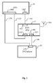
- Figure 3 shows a receiver device 21 that comprises an embodiment of the invention.
- DVD player 12 with analog output interface 1201
- DTT STB 21 comprises an analog input interface 2103 and a digital output interface 2101.
- DTV 10 now needs only one digital input interface 1002. Wiring is reduced to the minimum, each device is connected via a single connection to another device.
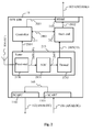
- FIG. 4 diagrammatically shows an embodiment of the invention in a receiver device 21 of figure 3 .
- the invention is implemented in a DTT STB 21 of which only components are shown that are of particular relevance for explanation of the invention. Components not shown are for example, memory, data-and communication bus, internal clock, and input means for control of the device 21 by a user.
- the DTT STB 21 comprises at least a controller 411, a tuner 413 that comprises a front-end 4130, an analog to digital convertor (ADC) 4131, demodulator 4132; and device 21 further comprises a back-end 412, switch 416, SCART interface 2103 and HDMI interface 2101. Switch 416 is further detailed in figure 5 .
- the switch 416 is controlled by controller 411.
- controller 411 All other components are also controlled by controller 411, via connections 4001 (to/from HDMI interface 2101), 4003 (to/from Back end 412), and 4004 (to/from tuner 413).
- controller 411 controls connections 4001 (to/from HDMI interface 2101), 4003 (to/from Back end 412), and 4004 (to/from tuner 413).
- the device 21 of the invention allows to use ADC 4131 either for the purpose of serving as an input for the demodulator 4132, or as an input for the back end 4005.
- the device 21 will receive an RF signal via antenna 104, tune and down convert it to a lower frequency (Intermediate Frequency or IF) with front end 4130, convert the analog IF signal in a digital IF signal with ADC 4131, and demodulate the digital IF signal with demodulator 4132 to finally output a digital audio/video signal 103 via back end 412 and HDMI interface 2101.
- a second position of switch 416 the device will receive an analog audio/video signal 106 received via SCART interface 2103, convert it to digital signal via ADC 4131, and output a digital audio/video signal 103 via back end 412 and HDMI interface 2101.
- device 21 functions as an RF receiver.
- device 21 functions as an analog to digital converter for analog audio/video signal 106.
- the backend 412 ensures further signal processing that comprises for example descrambling, extraction of information such as tables, and conversion of PAL (Phase Alternate Line) to 4:2:2.
- PAL Phase Alternate Line
- FIG. 5 shows a detailed embodiment of switch 416.
- the switch has two positions, a first position in which the device 21 is used as an RF receiver, and a second position in which device 21 is used as an analog-to-digital convertor of audio/video signals.
- the switch position that is depicted corresponds to the first position.
- FIGS. 3 and 4 show only two possible input sources, the invention allows to reuse an existing ADC that is present in a tuner of any receiver of digital RF signals, for analog to digital conversion of analog audio/video signals originating from either of two or more signal sources, such as 3, 4, 5 or 10 input sources.
- the two or more signal sources comprise a front end of a tuner and an analog audio/video input interface.
- the analog input signal after having been converted to a digital output signal by the analog to digital conversion, is being output on the digital audio/video interface as a digital audio/video signal after further processing by said device and thus reduces in the same time the number of hardware components and wiring needed to interface the devices.
- ADCs are for example present in DVB-C (Digital Video Broadcasting ⁇ Cable) receivers that integrate 10 bits ADCs used for RF demodulation, which are also sufficient for analog to digital conversion of audio/video signals.
- Other examples of decoding standards are DVB-C2, DVB-S2 and DVB-T2 (second generation standards for Cable, Satellite and Terrestrial receivers) that require ADCs for demodulation that are sufficiently powerful for analog to digital conversion of audio/video signals.
- the full-band ADCs which are used in next generation RF receivers are also largely sufficient for analog to digital conversion of audio/video signals. These full-band ADCs convert a complete RF reception band up to for example 1 GHz, and an RF receiver equipped with such a component does no longer implement a tuner function, i.e. frequency transposition of a chosen channel.
- the invention also allows an analog source of audio/video signals to take advantage of any additional signal handling already offered by the RF receiver device, such as video scaling (converting video signals from one size or resolution to another: usually “upscaling” or "upconverting" a video signal from a low resolution (e.g. SD or standard definition) to one of higher resolution (e.g. HDTV or high definition television).
- video scaling converting video signals from one size or resolution to another: usually "upscaling" or "upconverting" a video signal from a low resolution (e.g. SD or standard definition) to one of higher resolution (e.g. HDTV or high definition television).
- a device implementing the invention comprises the additional components needed for execution of these additional functions.
- Another advantage of the invention is that the particular interconnection of the devices made possible through the invention, allows for a more ergonomic operation.
- a user has to use a menu on his DTV to switch to a secondary input (for example AV1) of DTV 10 in order to render the analog audio/video signal of DVD player 12 on DTV 10
- AV1 secondary input
- the switch 416 switching automatically to the second position when the device 21 is put to a stand-by state.
- the device 21 automatically puts switch 416 in the second position when a signal is detected on interface 2103.
- device 21 offers it's user a manual choice, for example via a button on a remote control of device 21, to choose either the first or the second position of switch 416.
- Device 21 can be further optimized by allowing the demodulator output, when switch 416 is in the first position, to be output on interface 106, so that the user can for example connect a DVD recorder to interface 2103 to record a programme that is received via RF.
- the controller 411 controls the components of the receiver device 21 so that when switch 416 is put in either the first or the second position, resources not needed are switched off or put into a standby or low-power consumption mode, so that power consumption is reduced.
- the controller sets the switch 416 in a position to transfer audio/video signals from interface 2103 to ADC 4131, it switches off the front-end 4130 and demodulator 4132 via connection 4004.
- the full-band ADC can be configured by a controller such as controller 411 to reduce the sampling frequency in order to adapt to the analog audio/video signals of a range of 6-7Mhz originating from the analog audio/video signal source 2103 when the full-band ADC is not used to convert RF signals. This feature helps to reduce the power consumption of the device implementing the invention.
- the controller 411 controls any other components so as to change their parameterization or configuration. For example, when the controller sets switch 416 in the second position to transfer audio/video signals from interface 2103 to ADC 4131, it instructs the back-end 412 to do SD to HD video upscaling for the analog audio/video signal received from a DVD player such as DVD player 12 via connection 106.
- the discussed variant embodiments can be combined to form a particularly interesting variant with the combined advantages of each individual variant.
- Figure 6 shows an algorithm for implementing a particular embodiment of the method of the invention, implemented for example by the receiver device 21 of figure 3 .
- a step of selection of a source of audio/video signals for input into an analog to digital convertor (such as ADC 4131 of fig. 4 ) is done (steps 602, 603), for analog to digital conversion in a step 604 of an analog input signal (4006, 4008) that originates from either of at least two signal sources, for example such as from a tuner's 413 front end 4130 of device 21 of fig. 4 , or from an analog audio/video input interface such as SCART interface 2103 of device 21 of figure 4 .
- the analog to digital conversion is done by the analog to digital convertor of audio/video signals that is the origin of a digital audio/video signal (103) that is output on the digital audio/video output interface after any further processing.
- the method comprises a step of controlling the selection of the source signal through detection of a presence of a signal on either from either of the sources, such as on the analog audio/video input interface 2103 of device 21 of figure 4 . Upon such detection, the controller controls the switch 416 to change position.
- the method further comprises a step of reduction of power consumption of hardware components that are not needed in handling of those signal sources that are not connected to the analog to digital conversion.
- the invention is entirely implemented in hardware, for example as a dedicated component (for example as an ASIC, FPGA or VLSI) (respectively « Application Specific Integrated Circuit » « Field-Programmable Gate Array » and « Very Large Scale Integration ») or as distinct electronic components integrated in a device or in a form of a mix of hardware and software.
- a dedicated component for example as an ASIC, FPGA or VLSI
- VLSI Application Specific Integrated Circuit » « Field-Programmable Gate Array » and « Very Large Scale Integration »
Landscapes
- Engineering & Computer Science (AREA)
- Multimedia (AREA)
- Signal Processing (AREA)
- Two-Way Televisions, Distribution Of Moving Picture Or The Like (AREA)
- Television Systems (AREA)
- Circuits Of Receivers In General (AREA)
Abstract
Description
- The present invention generally relates to a method and device for handling of audio/video signals originating from a mix of analog and digital sources of audio/video signals. In particular, the present invention relates to optimization of hardware resources and of wiring needed for the interconnection of various analog and digital sources of audio/video signals.
- Manufacturers of consumer devices for reception and decoding of radio-frequency modulated audio/video signals for rendering of audiovisual services (e.g. satellite receivers, cable receivers, terrestrial receivers, digital televisions or mobile cell phones with integrated satellite, cable or terrestrial receivers), tend to minimize hardware resources of those devices in order to reduce production costs and ensure a competitive market price. In particular, processing and memory resources are tailored to the strictly needed.
- While the current trend is to a full-digital consumer electronic equipment, there are still many devices in consumer households that do not comply to the latest digital interconnection standards and interfaces, such as HDMI (High-Definition Multimedia Interface). Consumers are reluctant to change perfectly functioning devices with analog audio/video inputs and outputs for new devices just because their recently bought flat-screen digital television equipment does not allow to connect their existing equipment. Therefore, manufacturers still need to supply their latest digital consumer electronic devices with additional analog audio/video inputs for backwards compatibility.
- For consumers, the interconnection of the mix of analog and digital equipment, having different connection interfaces, is not easy to master and results in undesired quantity of unaesthetic and dust-retaining wiring.
- There is thus a need for optimization of the interconnection of analog and digital equipment and of the hardware resources needed in digital audio/video devices to connect to existing analog audio/video devices that avoids additional and complex wiring.
- The present invention aims at alleviating some of the inconveniences of prior art.
- The invention proposes a solution for optimization of the interconnection of analog and digital audio/video devices, that avoids among others the aforementioned drawbacks of prior art solutions.
- The term 'audio/video' and the abbreviation 'AV' is used in this document to indicate audio, video, or both audio and video.
- The invention proposes a device for reception of digital radio frequency modulated audio/video signals, comprising a digital audio/video output interface, and a tuner comprising an analog to digital convertor, the analog to digital convertor being used for analog to digital conversion of an analog input signal that originates from either of at least two signal sources, the at least two signal sources comprising a front end of the tuner and an analog audio/video input interface, the analog input signal, after having been converted to a digital output signal by the analog to digital conversion, being at the origin of a digital audio/video signal that is output on the digital audio/video interface after further processing by said device.
- In this manner, the digital audio/video signal finds its source (or 'origin') in for example either an RF modulated DVB-T signal transporting television or radio programmes, or an audio/video signal received from a DVD player via the device's analog AV interface.
- According to a variant embodiment of the invention, the device further comprises a switch for selection of either one of the at least two signal sources.
- According to a variant embodiment of the invention, the device further comprises a controller for controlling the switch.
- According to a variant embodiment of the invention, the controller reduces power consumption of hardware components of the device that are not needed according to the selection of either of said at least two signal sources.
- According to a variant embodiment of the invention, the device is a Set Top Box for reception of digital radio and television programs.
- According to a variant embodiment of the invention, the digital audio/video output interface is according to a High-Definition Multi-media Interface.
- According to a variant embodiment of the invention, the analog audio/video input interface is one of according to a
- Radio and Television Receiver Manufacturers' Association interface, also referred to as SCART, Péritel, EuroSCART, Euroconnector, EuroAV and EIA Multiport interface;
- S-Video interface; or
- CINCH interface.
- The invention also concerns a method for handling of audio/video signals, implemented by a device for reception of radio frequency modulated audio/video signals, the device comprising a digital audio/video output interface, the method comprising a step of selection of a source of audio/video signals for input into an analog to digital convertor for analog to digital conversion of an analog input signal that originates from either of at least two signal sources, the at least two signal sources comprising a front end of a tuner and an analog audio/video input interface, the analog input signal, after having been converted to a digital output signal by the analog to digital conversion, being at the origin of a digital audio/video signal that is output on the digital audio/video output interface after further processing by the device.
- According to a variant embodiment of the method, the method comprises a step of controlling the selection through determination of a presence of a analog audio/video signal on the analog audio/video input interface, said controlling determining a connection of one of said at least two signal sources to said analog to digital conversion.
- According to a variant embodiment of the method, the method comprises a step of reduction of power consumption of hardware components that are not needed in handling of those of the at least two signal sources that are not a source for the analog to digital conversion.
- The discussed advantages and other, not yet discussed advantages of the invention will appear through the following description of particular, non-restricting embodiments of the invention.
- The embodiments are described with reference to the following figures:
-
Figure 1 shows prior-art interconnection of analog and digital audio/video devices. -
Figure 2 shows prior-art device 11 offigure 1 in more detail. -
Figure 3 shows interconnection of analog and digital audio/video devices according to the invention. -
Figure 4 shows adevice 21 implementing an embodiment of the invention. -
Figure 5 shows a detailed embodiment ofswitch 416. -
Figure 6 shows an algorithm implementing a particular embodiment of the method of the invention, implemented for example by thereceiver device 21 offigure 4 . -
Figure 1 shows prior-art interconnection of analog and digital audio/video devices. Digital Terrestrial Television (DTT) Set Top Box (STB) 11 and aDVD player 12 are connected to adigital television 10. - DTV 10 is equipped with analog audio/
video input interface 1001 and digitalvideo input interface 1002. DTT STB 11 is equipped with a digital audio/video output interface 1101 and an analog audio/video input interface 1103 andoutput interface 1102.DVD player 12 is equipped with ananalog output interface 1201. For reception of a radio frequency (RF) signal,STB 11 is further connected to anantenna 104. - The figure shows several prior-art possibilities of interconnection for
DVD player 12 toDTV 10;DVD player 12 can either be connected directly toDTV 10 viaanalog connection 101, or indirectly, via STB 11 andanalog connections digital connection 103. In a typical situation, theanalog interfaces digital interfaces -
Figure 2 shows prior-art device 11 offigure 1 in more detail. Thedevice 11 receives the RF signal on itsantenna 104, which is handled bytuner 213 front-end 2130 where the variable frequency of the signals is converted to a fixed, lower frequency, which is then input into an analog-digital converter (ADC) 2131, and then demodulated bydemodulator 2132, finally outputting a digital signal in the form of an Transport Stream (TS), such as an MPEG-TS, ontuner output 2005. The tuner front-end 2130 allows, by means of thedevice controller 211, to choose a particular frequency from a frequency band, which is then down converted to a lower, fixed frequency and output onoutput 2006 to be input into theADC 2131. Finally, thetuner output 2005 is connected to aback end 212 for further treatment before outputting it by means ofconnection 2002 to theHDMI interface 1101, which outputs a HDMI signal viaconnection 103. A controller manages the functioning of the equipment viaconnections SCART input 1103 and SCART output are passive connectors that are interconnected vialink 105. Theinput signal 106 is thus looped via these interfaces tooutput signal 102. -
Figure 3 shows areceiver device 21 that comprises an embodiment of the invention. Compared to prior artfig. 1 , the number of interfaces and wiring is considerably reduced.DVD player 12, withanalog output interface 1201, is connected toDTV 10 via analog audio/video connection 106 thatlinks DVD player 12 to DTT STB 21 and via a digital audio/video connection 103 that links DTT STB 21 toDTV 10. DTT STB 21 comprises ananalog input interface 2103 and adigital output interface 2101. DTV 10 now needs only onedigital input interface 1002. Wiring is reduced to the minimum, each device is connected via a single connection to another device. -
Figure 4 diagrammatically shows an embodiment of the invention in areceiver device 21 offigure 3 . According to the particular implementation, the invention is implemented in aDTT STB 21 of which only components are shown that are of particular relevance for explanation of the invention. Components not shown are for example, memory, data-and communication bus, internal clock, and input means for control of thedevice 21 by a user. TheDTT STB 21 comprises at least acontroller 411, atuner 413 that comprises a front-end 4130, an analog to digital convertor (ADC) 4131,demodulator 4132; anddevice 21 further comprises a back-end 412,switch 416,SCART interface 2103 andHDMI interface 2101.Switch 416 is further detailed infigure 5 . Theswitch 416 is controlled bycontroller 411. All other components are also controlled bycontroller 411, via connections 4001 (to/from HDMI interface 2101), 4003 (to/from Back end 412), and 4004 (to/from tuner 413). Unlike theprior art device 11 offigures 1 and2 , thedevice 21 of the invention allows to useADC 4131 either for the purpose of serving as an input for thedemodulator 4132, or as an input for theback end 4005. In a first position ofswitch 416, depicted infigure 5 , thedevice 21 will receive an RF signal viaantenna 104, tune and down convert it to a lower frequency (Intermediate Frequency or IF) withfront end 4130, convert the analog IF signal in a digital IF signal withADC 4131, and demodulate the digital IF signal withdemodulator 4132 to finally output a digital audio/video signal 103 viaback end 412 andHDMI interface 2101. In a second position ofswitch 416, the device will receive an analog audio/video signal 106 received viaSCART interface 2103, convert it to digital signal viaADC 4131, and output a digital audio/video signal 103 viaback end 412 andHDMI interface 2101. Thus, in the first position ofswitch 416,device 21 functions as an RF receiver. In the second position ofswitch 416,device 21 functions as an analog to digital converter for analog audio/video signal 106. - The
backend 412 ensures further signal processing that comprises for example descrambling, extraction of information such as tables, and conversion of PAL (Phase Alternate Line) to 4:2:2. -
Figure 5 shows a detailed embodiment ofswitch 416. The switch has two positions, a first position in which thedevice 21 is used as an RF receiver, and a second position in whichdevice 21 is used as an analog-to-digital convertor of audio/video signals. The switch position that is depicted corresponds to the first position. - Although
figures 3 and4 show only two possible input sources, the invention allows to reuse an existing ADC that is present in a tuner of any receiver of digital RF signals, for analog to digital conversion of analog audio/video signals originating from either of two or more signal sources, such as 3, 4, 5 or 10 input sources. The two or more signal sources comprise a front end of a tuner and an analog audio/video input interface. The analog input signal after having been converted to a digital output signal by the analog to digital conversion, is being output on the digital audio/video interface as a digital audio/video signal after further processing by said device and thus reduces in the same time the number of hardware components and wiring needed to interface the devices. ADCs are for example present in DVB-C (Digital Video Broadcasting ― Cable) receivers that integrate 10 bits ADCs used for RF demodulation, which are also sufficient for analog to digital conversion of audio/video signals. Other examples of decoding standards are DVB-C2, DVB-S2 and DVB-T2 (second generation standards for Cable, Satellite and Terrestrial receivers) that require ADCs for demodulation that are sufficiently powerful for analog to digital conversion of audio/video signals. The full-band ADCs which are used in next generation RF receivers, are also largely sufficient for analog to digital conversion of audio/video signals. These full-band ADCs convert a complete RF reception band up to for example 1 GHz, and an RF receiver equipped with such a component does no longer implement a tuner function, i.e. frequency transposition of a chosen channel. - A part from the advantage procured by the invention of a double use of the ADC, the invention also allows an analog source of audio/video signals to take advantage of any additional signal handling already offered by the RF receiver device, such as video scaling (converting video signals from one size or resolution to another: usually "upscaling" or "upconverting" a video signal from a low resolution (e.g. SD or standard definition) to one of higher resolution (e.g. HDTV or high definition television). According to a variant embodiment of the invention, a device implementing the invention comprises the additional components needed for execution of these additional functions.
- Another advantage of the invention, is that the particular interconnection of the devices made possible through the invention, allows for a more ergonomic operation. Whereas according to prior art wiring such as illustrated by
figure 1 a user has to use a menu on his DTV to switch to a secondary input (for example AV1) ofDTV 10 in order to render the analog audio/video signal ofDVD player 12 onDTV 10, and according to a variant embodiment of the invention it is sufficient to switch offSTB 21 in order to render the audio/video ofDVD 12 onDTV 10, theswitch 416 switching automatically to the second position when thedevice 21 is put to a stand-by state. According to yet another variant embodiment, thedevice 21 automatically putsswitch 416 in the second position when a signal is detected oninterface 2103. According to yet another variant embodiment,device 21 offers it's user a manual choice, for example via a button on a remote control ofdevice 21, to choose either the first or the second position ofswitch 416.Device 21 can be further optimized by allowing the demodulator output, whenswitch 416 is in the first position, to be output oninterface 106, so that the user can for example connect a DVD recorder to interface 2103 to record a programme that is received via RF. - According to a variant embodiment of the invention illustrated by this figure, the
controller 411 controls the components of thereceiver device 21 so that whenswitch 416 is put in either the first or the second position, resources not needed are switched off or put into a standby or low-power consumption mode, so that power consumption is reduced. For example, when the controller sets theswitch 416 in a position to transfer audio/video signals frominterface 2103 toADC 4131, it switches off the front-end 4130 anddemodulator 4132 viaconnection 4004. In a particular receiver implemented with a full-band ADC that executes both the functions of the front-end 4130 andADC 4131, the full-band ADC can be configured by a controller such ascontroller 411 to reduce the sampling frequency in order to adapt to the analog audio/video signals of a range of 6-7Mhz originating from the analog audio/video signal source 2103 when the full-band ADC is not used to convert RF signals. This feature helps to reduce the power consumption of the device implementing the invention. - According to a variant embodiment of the invention, the
controller 411 controls any other components so as to change their parameterization or configuration. For example, when the controller sets switch 416 in the second position to transfer audio/video signals frominterface 2103 toADC 4131, it instructs the back-end 412 to do SD to HD video upscaling for the analog audio/video signal received from a DVD player such asDVD player 12 viaconnection 106. - According to a particular embodiment of the invention, the discussed variant embodiments can be combined to form a particularly interesting variant with the combined advantages of each individual variant.
-
Figure 6 shows an algorithm for implementing a particular embodiment of the method of the invention, implemented for example by thereceiver device 21 offigure 3 . - In a
first step 600, variables and attributes are initialized that are used by the algorithm. In anext step 601, a step of selection of a source of audio/video signals for input into an analog to digital convertor (such asADC 4131 offig. 4 ) is done (steps 602, 603), for analog to digital conversion in astep 604 of an analog input signal (4006, 4008) that originates from either of at least two signal sources, for example such as from a tuner's 413front end 4130 ofdevice 21 offig. 4 , or from an analog audio/video input interface such asSCART interface 2103 ofdevice 21 offigure 4 . Instep 604, the analog to digital conversion is done by the analog to digital convertor of audio/video signals that is the origin of a digital audio/video signal (103) that is output on the digital audio/video output interface after any further processing. - According to a variant embodiment, the method comprises a step of controlling the selection of the source signal through detection of a presence of a signal on either from either of the sources, such as on the analog audio/
video input interface 2103 ofdevice 21 offigure 4 . Upon such detection, the controller controls theswitch 416 to change position. - According to another variant embodiment, the method further comprises a step of reduction of power consumption of hardware components that are not needed in handling of those signal sources that are not connected to the analog to digital conversion.
- According to a particular embodiment, the invention is entirely implemented in hardware, for example as a dedicated component (for example as an ASIC, FPGA or VLSI) (respectively « Application Specific Integrated Circuit », « Field-Programmable Gate Array » and « Very Large Scale Integration ») or as distinct electronic components integrated in a device or in a form of a mix of hardware and software.
Claims (10)
- Device (21) for reception of digital radio frequency modulated audio/video signals, comprising a digital audio/video output interface (2101), characterized in that said device comprises:- a tuner (413) comprising an analog to digital convertor (4131), said analog to digital convertor (4131) being used for analog to digital conversion of an analog input signal (4006, 4008) that originates from either of at least two signal sources (4130, 2103), said at least two signal sources comprising a front end (4130) of said tuner (4130) and an analog audio/video input interface (2103), said analog input signal (4006, 4008), after having been converted to a digital output signal by said analog to digital conversion, being at the origin of a digital output audio/video signal (103) that is output on said digital audio/video interface (2101) after further processing by said device (4132, 412, 2101).
- Device (21) according to claim 1, characterized in that said device (21) further comprises a switch (416) for selection of either one of said at least two signal sources (4130, 2103).
- Device (21) according to claim 2, characterized in that said device (21) further comprises a controller (411) for controlling said switch (416).
- Device (21) according to claim 3, characterized in that said controller (416) reduces power consumption of hardware components of said device (21) that are not needed according to said selection of either of said at least two signal sources.
- Device (21) according to any of claims 1 to 4, characterized in that said device (21) is a Set Top Box for reception of digital radio and television programs.
- Device (21) according to any of claims 1 to 5, characterized in that said digital audio/video output interface (2101) is according to a High-Definition Multi-media Interface.
- Device (21) according to any of claims 1 to 6, characterized in that said analog audio/video input interface (2103) is one of according to a- Radio and Television Receiver Manufacturers' Association interface, also referred to as SCART, Péritel, EuroSCART, Euroconnector, EuroAV and EIA Multiport interface;- S-Video interface; or- CINCH interface.
- Method for handling of audio/video signals, implemented by a device (21) for reception of digital radio frequency modulated audio/video signals, said device (21) comprising a digital audio/video output interface (2101), said method being characterized in that it comprises the following step:- selection (601) of a source of audio/video signals for input into an analog to digital convertor (4131) for analog to digital conversion of an analog input signal (4006, 4008) that originates from either of at least two signal sources (4130, 2103), said at least two signal sources comprising a front end (4130) of a tuner (4130) and an analog audio/video input interface (2103), said analog input signal (4006, 4008), after having been converted to a digital output signal by said analog to digital conversion, being at the origin of a digital audio/video signal (103) that is output on said digital audio/video output interface (2101) after further processing by said device (4132, 412, 2101).
- Method according to claim 8, characterized in that said method further comprises a step of controlling said selection through determination of a presence of a analog audio/video signal (106) on said analog audio/video input interface (2103), said controlling determining a connection of one of said at least two signal sources (4130, 2103) to said analog to digital conversion.
- Method according to any of claim 9, characterized in that said method further comprises a step of reduction of power consumption of hardware components that are not needed in handling of those of said at least two signal sources that are not a source for said analog to digital conversion.
Priority Applications (1)
| Application Number | Priority Date | Filing Date | Title |
|---|---|---|---|
| EP11172897A EP2416566A3 (en) | 2010-08-05 | 2011-07-06 | Method for handling of audio/video signals and corresponding device |
Applications Claiming Priority (2)
| Application Number | Priority Date | Filing Date | Title |
|---|---|---|---|
| EP10305864A EP2416565A1 (en) | 2010-08-05 | 2010-08-05 | Method for handling of audio/video signals and corresponding device |
| EP11172897A EP2416566A3 (en) | 2010-08-05 | 2011-07-06 | Method for handling of audio/video signals and corresponding device |
Publications (2)
| Publication Number | Publication Date |
|---|---|
| EP2416566A2 true EP2416566A2 (en) | 2012-02-08 |
| EP2416566A3 EP2416566A3 (en) | 2012-09-05 |
Family
ID=43127612
Family Applications (2)
| Application Number | Title | Priority Date | Filing Date |
|---|---|---|---|
| EP10305864A Withdrawn EP2416565A1 (en) | 2010-08-05 | 2010-08-05 | Method for handling of audio/video signals and corresponding device |
| EP11172897A Ceased EP2416566A3 (en) | 2010-08-05 | 2011-07-06 | Method for handling of audio/video signals and corresponding device |
Family Applications Before (1)
| Application Number | Title | Priority Date | Filing Date |
|---|---|---|---|
| EP10305864A Withdrawn EP2416565A1 (en) | 2010-08-05 | 2010-08-05 | Method for handling of audio/video signals and corresponding device |
Country Status (2)
| Country | Link |
|---|---|
| US (1) | US8769603B2 (en) |
| EP (2) | EP2416565A1 (en) |
Families Citing this family (5)
| Publication number | Priority date | Publication date | Assignee | Title |
|---|---|---|---|---|
| CA2716987C (en) * | 2008-03-07 | 2016-06-28 | Ek3 Technologies, Inc | Fault detection and correction for single and multiple media players connected to electronic displays, and related devices, methods and systems |
| CN104796630B (en) * | 2015-05-13 | 2018-08-10 | 长沙楚风数码科技有限公司 | A kind of distributed signal switched transmission method |
| CN106412647B (en) * | 2015-07-29 | 2019-05-31 | 国基电子(上海)有限公司 | Signal switching system and set-top box using the same |
| CN105898454A (en) * | 2015-11-20 | 2016-08-24 | 乐视致新电子科技(天津)有限公司 | Signal processing device and multimedia playback device |
| CN105808481B (en) * | 2016-03-03 | 2018-08-14 | 四川长虹电器股份有限公司 | The device of HDMI interface multiplexing transmission SCART and HDMI signal |
Citations (2)
| Publication number | Priority date | Publication date | Assignee | Title |
|---|---|---|---|---|
| WO2010050938A1 (en) * | 2008-10-29 | 2010-05-06 | Hewlett-Packard Development Company, L.P. | Modular television input |
| EP2242257A1 (en) * | 2009-04-15 | 2010-10-20 | Himax Media Solutions, Inc. | Audio/video signal processor |
Family Cites Families (20)
| Publication number | Priority date | Publication date | Assignee | Title |
|---|---|---|---|---|
| JP2921265B2 (en) * | 1992-06-08 | 1999-07-19 | 松下電器産業株式会社 | Television receiver |
| KR960020415A (en) * | 1994-11-23 | 1996-06-17 | 윌리엄 이. 힐러 | Special features for digital television |
| US6229575B1 (en) * | 1997-03-31 | 2001-05-08 | Compaq Computer Corporation | Computer convergence device controller for managing disparate video sources |
| US6690431B1 (en) * | 1999-08-02 | 2004-02-10 | Mg International (Zhong Shan) Co., Ltd. | Audio/video amplifier with the function of automatic turning on/off |
| US20040008972A1 (en) * | 2001-03-29 | 2004-01-15 | Koninklijke Philips Electronics N.V. | Personal TV receiver (PTR) with program recommendation forwarding function |
| CN1813472A (en) * | 2003-06-27 | 2006-08-02 | 皇家飞利浦电子股份有限公司 | Receiver and method for reducing power consumption in low-power mode |
| US20050134746A1 (en) * | 2003-12-18 | 2005-06-23 | Brandt Nicholas C. | Controllable video switching method and apparatus |
| KR20050070953A (en) * | 2003-12-31 | 2005-07-07 | 삼성전자주식회사 | Analogue/digital signal processing apparatus for outputting the analogue input signal without eliminating the copy protection signal included therein and method thereof |
| KR100539537B1 (en) * | 2003-12-31 | 2005-12-29 | 엘지전자 주식회사 | TV with input Labeling and Labeling Method the Same |
| JP2005333472A (en) * | 2004-05-20 | 2005-12-02 | Toshiba Corp | Video signal receiving apparatus and video signal receiving method |
| JP2005347871A (en) * | 2004-05-31 | 2005-12-15 | Sony Corp | Television receiver |
| US20080007616A1 (en) * | 2004-12-06 | 2008-01-10 | Ftd Technology Pte. Ltd. | Universal multimedia display adapter |
| WO2006091740A2 (en) * | 2005-02-24 | 2006-08-31 | Humanizing Technologies, Inc. | User-configuration multimedia presentation system |
| TWI266533B (en) * | 2005-06-29 | 2006-11-11 | Avermedia Tech Inc | Analog/digital set-top box |
| KR100758903B1 (en) * | 2005-12-13 | 2007-09-17 | 엘지전자 주식회사 | Broadcast receiver capable of recording / playback and recording / playback method |
| FR2910217A1 (en) * | 2006-12-14 | 2008-06-20 | St Microelectronics Sa | VIDEO DETECTION CELL |
| US20090119732A1 (en) * | 2007-11-02 | 2009-05-07 | Thomas Spieker | Method and system for direct sampled digital and analog demodulator tv receiver with backwards compatibility |
| KR101512379B1 (en) * | 2008-07-01 | 2015-04-16 | 삼성전자 주식회사 | Integrated circuit device for processing signal and image processing apparatus having the same |
| US20100095342A1 (en) * | 2008-08-06 | 2010-04-15 | Belkin International, Inc. | Wireless content transmission and control |
| KR20100042784A (en) * | 2008-10-17 | 2010-04-27 | 삼성전자주식회사 | Apparatus and method for receiving broadcasting of two mode using one tuner in set top box |
-
2010
- 2010-08-05 EP EP10305864A patent/EP2416565A1/en not_active Withdrawn
-
2011
- 2011-07-06 EP EP11172897A patent/EP2416566A3/en not_active Ceased
- 2011-08-02 US US13/136,483 patent/US8769603B2/en active Active
Patent Citations (2)
| Publication number | Priority date | Publication date | Assignee | Title |
|---|---|---|---|---|
| WO2010050938A1 (en) * | 2008-10-29 | 2010-05-06 | Hewlett-Packard Development Company, L.P. | Modular television input |
| EP2242257A1 (en) * | 2009-04-15 | 2010-10-20 | Himax Media Solutions, Inc. | Audio/video signal processor |
Also Published As
| Publication number | Publication date |
|---|---|
| US20120036548A1 (en) | 2012-02-09 |
| EP2416565A1 (en) | 2012-02-08 |
| EP2416566A3 (en) | 2012-09-05 |
| US8769603B2 (en) | 2014-07-01 |
Similar Documents
| Publication | Publication Date | Title |
|---|---|---|
| JP6097559B2 (en) | Front-end integrated circuit of broadcast receiving system, broadcast receiving system including the same, and operation method thereof | |
| US8769603B2 (en) | Method for handling of audio/video signals and corresponding device | |
| US8482676B2 (en) | Differential antenna and associated control system applied to digital TV | |
| TWI487372B (en) | Apparatus and method for scanning channels, analog and digital television receivers, and computer readable media | |
| US10349112B2 (en) | Method and system for multi-path video and network channels | |
| US20120026407A1 (en) | System and Method for Configurable Multi-standard Receiver | |
| US9311957B2 (en) | Multi-channel audio signal converting device using time-varying digital filter, electronic system including the same, and method of converting multi-channel audio signal | |
| WO2015078416A1 (en) | Television signal receiving module and receiving method | |
| CN101567989A (en) | Television receiving system | |
| CN204334857U (en) | The digital TV set-top box of a kind of compatible with DVB-C, DTMB-TH transmission medium | |
| CN102256082B (en) | Television set supporting multiple digital television systems | |
| US9172988B2 (en) | Analog front end for DTV, DTV system having the same, and operation methods thereof | |
| US8373803B2 (en) | Multistandard receiver circuit for analogue and digital broadcasting | |
| CN103731713A (en) | Television signal receiving system and method | |
| CN201467265U (en) | Top box of digital-analog mixed receiver | |
| CN210629669U (en) | Intelligent digital television | |
| RU139321U1 (en) | TELEVISION DIGITAL STB | |
| EP1679888A1 (en) | Television tuning apparatus for operating in analogue or digital receiving mode | |
| CN203675198U (en) | Television signal receiving module | |
| CN2932863Y (en) | Digital set-top box | |
| CN201754602U (en) | Television module for computer | |
| CN203675249U (en) | Television signal receiving system | |
| KR101789493B1 (en) | Analog front end for dtv, digital tv system having the same, and methods thereof | |
| Holla et al. | Performance enhancement of network interface module in high definition receivers | |
| CN101227569A (en) | Television box and television box group |
Legal Events
| Date | Code | Title | Description |
|---|---|---|---|
| AK | Designated contracting states |
Kind code of ref document: A2 Designated state(s): AL AT BE BG CH CY CZ DE DK EE ES FI FR GB GR HR HU IE IS IT LI LT LU LV MC MK MT NL NO PL PT RO RS SE SI SK SM TR |
|
| AX | Request for extension of the european patent |
Extension state: BA ME |
|
| PUAI | Public reference made under article 153(3) epc to a published international application that has entered the european phase |
Free format text: ORIGINAL CODE: 0009012 |
|
| PUAL | Search report despatched |
Free format text: ORIGINAL CODE: 0009013 |
|
| AK | Designated contracting states |
Kind code of ref document: A3 Designated state(s): AL AT BE BG CH CY CZ DE DK EE ES FI FR GB GR HR HU IE IS IT LI LT LU LV MC MK MT NL NO PL PT RO RS SE SI SK SM TR |
|
| AX | Request for extension of the european patent |
Extension state: BA ME |
|
| RIC1 | Information provided on ipc code assigned before grant |
Ipc: H04N 5/00 20110101ALI20120731BHEP Ipc: H04N 21/40 20110101ALI20120731BHEP Ipc: H04N 21/426 20110101ALI20120731BHEP Ipc: H04N 21/41 20110101ALI20120731BHEP Ipc: H04N 5/46 20060101AFI20120731BHEP Ipc: H04N 5/44 20110101ALI20120731BHEP |
|
| 17P | Request for examination filed |
Effective date: 20130226 |
|
| 17Q | First examination report despatched |
Effective date: 20130822 |
|
| STAA | Information on the status of an ep patent application or granted ep patent |
Free format text: STATUS: THE APPLICATION HAS BEEN REFUSED |
|
| 18R | Application refused |
Effective date: 20160211 |