EP2416415A1 - Fuel battery - Google Patents
Fuel battery Download PDFInfo
- Publication number
- EP2416415A1 EP2416415A1 EP09842631A EP09842631A EP2416415A1 EP 2416415 A1 EP2416415 A1 EP 2416415A1 EP 09842631 A EP09842631 A EP 09842631A EP 09842631 A EP09842631 A EP 09842631A EP 2416415 A1 EP2416415 A1 EP 2416415A1
- Authority
- EP
- European Patent Office
- Prior art keywords
- gas
- gas passage
- continuous pores
- forming member
- passage forming
- Prior art date
- Legal status (The legal status is an assumption and is not a legal conclusion. Google has not performed a legal analysis and makes no representation as to the accuracy of the status listed.)
- Granted
Links
- 239000000446 fuel Substances 0.000 title claims abstract description 84
- 239000011148 porous material Substances 0.000 claims abstract description 134
- XLYOFNOQVPJJNP-UHFFFAOYSA-N water Substances O XLYOFNOQVPJJNP-UHFFFAOYSA-N 0.000 claims abstract description 111
- 230000001737 promoting effect Effects 0.000 claims abstract description 106
- 230000003647 oxidation Effects 0.000 claims abstract description 83
- 238000007254 oxidation reaction Methods 0.000 claims abstract description 83
- 238000007599 discharging Methods 0.000 claims abstract description 69
- 230000009471 action Effects 0.000 claims abstract description 23
- 239000012530 fluid Substances 0.000 claims abstract description 19
- 239000007789 gas Substances 0.000 claims description 349
- 239000003054 catalyst Substances 0.000 claims description 100
- 239000002737 fuel gas Substances 0.000 claims description 78
- 239000012528 membrane Substances 0.000 claims description 31
- 239000003792 electrolyte Substances 0.000 claims description 15
- 239000000463 material Substances 0.000 claims description 12
- 230000036571 hydration Effects 0.000 claims description 10
- 238000006703 hydration reaction Methods 0.000 claims description 10
- 238000010248 power generation Methods 0.000 abstract description 55
- 238000009792 diffusion process Methods 0.000 abstract description 30
- 239000002245 particle Substances 0.000 description 16
- 239000001257 hydrogen Substances 0.000 description 15
- 229910052739 hydrogen Inorganic materials 0.000 description 15
- 239000007784 solid electrolyte Substances 0.000 description 15
- UFHFLCQGNIYNRP-UHFFFAOYSA-N Hydrogen Chemical compound [H][H] UFHFLCQGNIYNRP-UHFFFAOYSA-N 0.000 description 14
- OKTJSMMVPCPJKN-UHFFFAOYSA-N Carbon Chemical compound [C] OKTJSMMVPCPJKN-UHFFFAOYSA-N 0.000 description 12
- 229910052799 carbon Inorganic materials 0.000 description 12
- BASFCYQUMIYNBI-UHFFFAOYSA-N platinum Chemical compound [Pt] BASFCYQUMIYNBI-UHFFFAOYSA-N 0.000 description 12
- 230000007812 deficiency Effects 0.000 description 10
- QVGXLLKOCUKJST-UHFFFAOYSA-N atomic oxygen Chemical compound [O] QVGXLLKOCUKJST-UHFFFAOYSA-N 0.000 description 7
- 239000001301 oxygen Substances 0.000 description 7
- 229910052760 oxygen Inorganic materials 0.000 description 7
- 238000006243 chemical reaction Methods 0.000 description 6
- -1 hydrogen ions Chemical class 0.000 description 6
- 230000007797 corrosion Effects 0.000 description 5
- 238000005260 corrosion Methods 0.000 description 5
- 239000002184 metal Substances 0.000 description 5
- 229910052751 metal Inorganic materials 0.000 description 5
- 229910052697 platinum Inorganic materials 0.000 description 5
- 230000009467 reduction Effects 0.000 description 5
- 229910001220 stainless steel Inorganic materials 0.000 description 5
- 239000010935 stainless steel Substances 0.000 description 5
- CURLTUGMZLYLDI-UHFFFAOYSA-N Carbon dioxide Chemical compound O=C=O CURLTUGMZLYLDI-UHFFFAOYSA-N 0.000 description 3
- 230000003628 erosive effect Effects 0.000 description 3
- 229920002313 fluoropolymer Polymers 0.000 description 3
- 239000004811 fluoropolymer Substances 0.000 description 3
- 229910000859 α-Fe Inorganic materials 0.000 description 3
- IJGRMHOSHXDMSA-UHFFFAOYSA-N Atomic nitrogen Chemical compound N#N IJGRMHOSHXDMSA-UHFFFAOYSA-N 0.000 description 2
- MYMOFIZGZYHOMD-UHFFFAOYSA-N Dioxygen Chemical compound O=O MYMOFIZGZYHOMD-UHFFFAOYSA-N 0.000 description 2
- JOYRKODLDBILNP-UHFFFAOYSA-N Ethyl urethane Chemical compound CCOC(N)=O JOYRKODLDBILNP-UHFFFAOYSA-N 0.000 description 2
- RTAQQCXQSZGOHL-UHFFFAOYSA-N Titanium Chemical compound [Ti] RTAQQCXQSZGOHL-UHFFFAOYSA-N 0.000 description 2
- 229910002092 carbon dioxide Inorganic materials 0.000 description 2
- 230000002950 deficient Effects 0.000 description 2
- 229910001873 dinitrogen Inorganic materials 0.000 description 2
- 229910001882 dioxygen Inorganic materials 0.000 description 2
- 238000005242 forging Methods 0.000 description 2
- PCHJSUWPFVWCPO-UHFFFAOYSA-N gold Chemical compound [Au] PCHJSUWPFVWCPO-UHFFFAOYSA-N 0.000 description 2
- 239000010931 gold Substances 0.000 description 2
- 229910052737 gold Inorganic materials 0.000 description 2
- 150000002431 hydrogen Chemical class 0.000 description 2
- 239000010936 titanium Substances 0.000 description 2
- 229910052719 titanium Inorganic materials 0.000 description 2
- 238000011144 upstream manufacturing Methods 0.000 description 2
- 229910009112 xH2O Inorganic materials 0.000 description 2
- 239000001569 carbon dioxide Substances 0.000 description 1
- 239000002800 charge carrier Substances 0.000 description 1
- 239000002826 coolant Substances 0.000 description 1
- 230000000694 effects Effects 0.000 description 1
- 238000003487 electrochemical reaction Methods 0.000 description 1
- 238000003411 electrode reaction Methods 0.000 description 1
- XLYOFNOQVPJJNP-ZSJDYOACSA-N heavy water Substances [2H]O[2H] XLYOFNOQVPJJNP-ZSJDYOACSA-N 0.000 description 1
- 230000004048 modification Effects 0.000 description 1
- 238000012986 modification Methods 0.000 description 1
- 229920000642 polymer Polymers 0.000 description 1
- 229920006254 polymer film Polymers 0.000 description 1
- 230000036647 reaction Effects 0.000 description 1
- 230000000717 retained effect Effects 0.000 description 1
- 239000007787 solid Substances 0.000 description 1
- 239000000126 substance Substances 0.000 description 1
- 125000001273 sulfonato group Chemical group [O-]S(*)(=O)=O 0.000 description 1
- 229920003051 synthetic elastomer Polymers 0.000 description 1
- 229920003002 synthetic resin Polymers 0.000 description 1
- 239000000057 synthetic resin Substances 0.000 description 1
- 239000005061 synthetic rubber Substances 0.000 description 1
Images




Classifications
-
- H—ELECTRICITY
- H01—ELECTRIC ELEMENTS
- H01M—PROCESSES OR MEANS, e.g. BATTERIES, FOR THE DIRECT CONVERSION OF CHEMICAL ENERGY INTO ELECTRICAL ENERGY
- H01M8/00—Fuel cells; Manufacture thereof
- H01M8/04—Auxiliary arrangements, e.g. for control of pressure or for circulation of fluids
- H01M8/04291—Arrangements for managing water in solid electrolyte fuel cell systems
-
- H—ELECTRICITY
- H01—ELECTRIC ELEMENTS
- H01M—PROCESSES OR MEANS, e.g. BATTERIES, FOR THE DIRECT CONVERSION OF CHEMICAL ENERGY INTO ELECTRICAL ENERGY
- H01M8/00—Fuel cells; Manufacture thereof
- H01M8/02—Details
- H01M8/0202—Collectors; Separators, e.g. bipolar separators; Interconnectors
- H01M8/023—Porous and characterised by the material
- H01M8/0241—Composites
-
- H—ELECTRICITY
- H01—ELECTRIC ELEMENTS
- H01M—PROCESSES OR MEANS, e.g. BATTERIES, FOR THE DIRECT CONVERSION OF CHEMICAL ENERGY INTO ELECTRICAL ENERGY
- H01M8/00—Fuel cells; Manufacture thereof
- H01M8/02—Details
- H01M8/0202—Collectors; Separators, e.g. bipolar separators; Interconnectors
- H01M8/0247—Collectors; Separators, e.g. bipolar separators; Interconnectors characterised by the form
-
- H—ELECTRICITY
- H01—ELECTRIC ELEMENTS
- H01M—PROCESSES OR MEANS, e.g. BATTERIES, FOR THE DIRECT CONVERSION OF CHEMICAL ENERGY INTO ELECTRICAL ENERGY
- H01M8/00—Fuel cells; Manufacture thereof
- H01M8/02—Details
- H01M8/0202—Collectors; Separators, e.g. bipolar separators; Interconnectors
- H01M8/0267—Collectors; Separators, e.g. bipolar separators; Interconnectors having heating or cooling means, e.g. heaters or coolant flow channels
-
- H—ELECTRICITY
- H01—ELECTRIC ELEMENTS
- H01M—PROCESSES OR MEANS, e.g. BATTERIES, FOR THE DIRECT CONVERSION OF CHEMICAL ENERGY INTO ELECTRICAL ENERGY
- H01M8/00—Fuel cells; Manufacture thereof
- H01M8/10—Fuel cells with solid electrolytes
- H01M8/1004—Fuel cells with solid electrolytes characterised by membrane-electrode assemblies [MEA]
-
- H—ELECTRICITY
- H01—ELECTRIC ELEMENTS
- H01M—PROCESSES OR MEANS, e.g. BATTERIES, FOR THE DIRECT CONVERSION OF CHEMICAL ENERGY INTO ELECTRICAL ENERGY
- H01M8/00—Fuel cells; Manufacture thereof
- H01M8/24—Grouping of fuel cells, e.g. stacking of fuel cells
- H01M8/241—Grouping of fuel cells, e.g. stacking of fuel cells with solid or matrix-supported electrolytes
- H01M8/242—Grouping of fuel cells, e.g. stacking of fuel cells with solid or matrix-supported electrolytes comprising framed electrodes or intermediary frame-like gaskets
-
- H—ELECTRICITY
- H01—ELECTRIC ELEMENTS
- H01M—PROCESSES OR MEANS, e.g. BATTERIES, FOR THE DIRECT CONVERSION OF CHEMICAL ENERGY INTO ELECTRICAL ENERGY
- H01M8/00—Fuel cells; Manufacture thereof
- H01M8/02—Details
- H01M8/0202—Collectors; Separators, e.g. bipolar separators; Interconnectors
- H01M8/0258—Collectors; Separators, e.g. bipolar separators; Interconnectors characterised by the configuration of channels, e.g. by the flow field of the reactant or coolant
-
- Y—GENERAL TAGGING OF NEW TECHNOLOGICAL DEVELOPMENTS; GENERAL TAGGING OF CROSS-SECTIONAL TECHNOLOGIES SPANNING OVER SEVERAL SECTIONS OF THE IPC; TECHNICAL SUBJECTS COVERED BY FORMER USPC CROSS-REFERENCE ART COLLECTIONS [XRACs] AND DIGESTS
- Y02—TECHNOLOGIES OR APPLICATIONS FOR MITIGATION OR ADAPTATION AGAINST CLIMATE CHANGE
- Y02E—REDUCTION OF GREENHOUSE GAS [GHG] EMISSIONS, RELATED TO ENERGY GENERATION, TRANSMISSION OR DISTRIBUTION
- Y02E60/00—Enabling technologies; Technologies with a potential or indirect contribution to GHG emissions mitigation
- Y02E60/30—Hydrogen technology
- Y02E60/50—Fuel cells
Definitions
- the present invention relates to a fuel battery that is mounted, for example, on an electric car.
- a fuel battery has a cell stack formed by a number of power generation cells stacked together.
- a prior art power generation cell will be described.
- a pair of frames 13, 14 are connected to each other, and an electrode structure 15 is installed at the joint portion of the frames 13, 14.
- the electrode structure 15 is formed by a solid electrolyte membrane 16, an electrode catalyst layer 17 on the anode side, and an electrode catalyst layer 18 on the cathode side.
- the outer periphery of the solid electrolyte membrane 16 is held between the frames 13, 14.
- the anode-side electrode catalyst layer 17 is laid on the upper surface of the electrolyte membrane 16, and the cathode-side electrode catalyst layer 18 is laid on the lower surface of the electrolyte membrane 16.
- An anode-side gas diffusion layer 19 is laid on the upper surface of the electrode catalyst layer 17, and a cathode-side gas diffusion layer 20 is laid on the lower surface of the electrode catalyst layer 18.
- an anode-side gas passage forming member 21 is laid on the upper surface of the gas diffusion layer 19, and a cathode-side gas passage forming member 22 is laid on the lower surface of the gas diffusion layer 20.
- a flat plate-like separator 23 is joined to the upper surface of the gas passage forming member 21, and a flat plate-like separator 24 is joined to the lower surface of the gas passage forming member 22.
- the solid electrolyte membrane 16 is formed of a fluoropolymer film.
- the electrode catalyst layers 17, 18 each have granular carbon particles 51 supporting a platinum catalyst, and a great number of platinum (Pt) catalyst particles 52 adhere to the surface of each carbon particle 51.
- the electrode catalyst layers 17, 18 are bonded to the solid electrolyte membrane 16 by paste for forming an electrode catalyst layer.
- the catalyst particles 52 serving as a catalyst increase the power generation efficiency when power is generated by the fuel battery.
- the gas diffusion layers 19, 20 are formed of carbon paper.
- the gas passage forming member 21 (22) is formed of a metal lath, which has a great number of hexagonal ring portions 21a (22a) arranged alternately.
- Each ring portion 21a (22a) has a through hole 21b (22b).
- Fuel gas oxidation gas flows through gas passages formed by the ring portions 21a (22a) and the through holes 21b (22b).
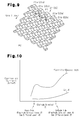
- Fig. 9 is an enlarged view showing a part of the gas passage forming member 21, 22.
- the frames 13, 14 form a supply passage M1 and a discharging passage M2 for fuel gas.
- the fuel gas supply passage M1 is used for supplying hydrogen gas, which serves as fuel gas, to the gas passages of the anode-side gas passage forming member 21.
- the fuel gas discharging passage M2 is used for discharging fuel gas that has passed through the gas passages of the gas passage forming member 21, or fuel off-gas, to the outside.
- the frames 13, 14 form a supply passage and a discharging passage for oxidation gas.
- the oxidation gas supply passage is located at a position corresponding to the back side of the sheet of Fig.
- the oxidation gas discharging passage is located at a position corresponding to the front side of the sheet of Fig. 7 , and is used for discharging oxidation gas that has passed through the gas passages of the gas passage forming member 22, or oxidation off-gas, to the outside.
- Hydrogen gas from a hydrogen gas supply source (not shown) is supplied to the gas passage forming member 21 through the fuel gas supply passage M1 along a gas flow direction P indicated by an arrow in Fig. 7 , and air is supplied to the gas passage forming member 22 from an air supply source (not shown). Accordingly, power is generated through an electrochemical reaction in the power generation cell. Specifically, hydrogen gas (H 2 ) supplied to the anode-side gas passage forming member 21 flows into the electrode catalyst layer 17 through the gas diffusion layer 19.
- H 2 hydrogen
- H + hydrogen ions
- e - electrons
- Hydrogen ions (H + ) obtained through the above reaction reaches the cathode-side electrode catalyst layer 18 from the anode-side electrode catalyst layer 17 through the solid electrolyte membrane 16.
- Oxygen (O 2 ) in the air supplied to the electrode catalyst layer 18 from the gas passage forming member 22 chemically reacts with the hydrogen ions (H + ) and the electrons (e - ), which generates water as shown by the formula (2).
- the potential of the electrode catalyst layer 18 becomes approximately 1.0 volt, or the standard electrode potential, as known in the art. 1/2 ⁇ O 2 + 2H + + + 2e - ⁇ H 2 O (2)
- the potential of the anode-side electrode catalyst layer 17 (the gas diffusion layer 19) is lower than the potential of the cathode-side electrode catalyst layer 18 (the gas diffusion layer 20), as shown in Fig. 10 .
- the anode-side gas passage forming member 21 is less susceptible to metallic oxidation due to a high potential. Therefore, as shown in Fig. 10 , an inexpensive stainless steel such as ferrite-based SUS having a low corrosion resistance is used as the material of the gas passage forming member 21.
- Patent Document 1 discloses a fuel battery having a similar structure to the structure shown in Fig. 7 .
- some of the hydrogen gas is not used in power generation and is drained as fuel off-gas to the outside through the gas passage of the gas passage forming member 21 and the discharging passage M2.
- Some of the oxygen gas that has not been reduced during the power generation is drained as oxidation off-gas to the outside through the discharging passage (not shown) formed in the frames 13, 14, together with water generated through the reaction of the formula (2) and nitrogen gas in air.
- Some of the generated water flows into the gas passage of the gas passage forming member 21, while seeping as seepage water through the cathode-side electrode catalyst layer 18, the solid electrolyte membrane 16, the anode-side electrode catalyst layer 17, and the gas diffusion layer 19. The seepage water is drained to the outside through the gas passage of the gas passage forming member 21 and the discharging passage M2, together with the fuel off-gas.
- the gas passage forming member 21 (22) has a great number of hexagonal ring portions 21a (22a) arranged alternately, and fuel gas flows through gas passages formed by the ring portions 21a (22a) and the through holes 21b (22b).
- the seepage water (generated water) is likely to adhere to the wall surfaces of the gas passage, which meanders in a complex manner, due to surface tension. Therefore, some of the seepage water (generated water) from the gas passage of the gas passage forming member 21 (22) is not drained to the outside but remains in the gas passage as droplets.
- the seepage water (generated) remaining in the gas passage causes the following problems.
- oxygen (O 2 ) that has entered the anode-side electrode catalyst layer 17 is reduced by hydrated protons (hydrogen ions with water molecules H + ⁇ xH 2 O) that exist in the fluoropolymer film of the solid electrolyte membrane 16. That is, the hydrated protons react with oxygen and negatively-charged electrons to generate water as shown by the formula (3) shown below.
- the hydrated protons are charge carriers of the polymer film forming the solid electrolyte membrane 16, and move among sulfonate groups (-SO 3 - -). The hydrated protons then move from the solid electrolyte membrane 16 to the electrode catalyst layer 17. 1/2 ⁇ O 2 + 2H + + 2e - ⁇ H 2 O (3)
- the standard electrode potential of the layers 17, 19, which are deficient in hydrogen due to the reaction of the formula (3) increases to approximately 1.0 volt.
- the increase of the standard electrode potential of the layers 17, 19 corrodes and oxidizes the gas passage forming member 21, which is formed of ferrite-based SUS having a low corrosion resistance, thus reducing the durability.
- the gas passage forming member 21 is corroded and oxidized, its electric resistance is increased, which hampers the flow of generated power. This in turn lowers the power generation output.
- the hydrated protons (hydrogen ions H + ⁇ xH 2 O) that form the solid electrolyte membrane 16 decrease.
- carbon (C) forming the electrode catalyst layer 18 and water are reacted as shown by the formula (4), so that carbon dioxide and hydrogen ions (H + ) are generated.
- This fuel battery includes porous members 61, 62 having continuous pores.
- the porous members 61, 62 are located between an anode-side gas passage forming member 21 and a separator 23 and between a cathode-side gas passage forming member 22 and a separator 24, respectively.
- the porous members 61, 62 each have a three-layer structure of a first porous layer, a second porous layer, and a dense layer. The size of the continuous pores are reduced in that order.
- the anode-side porous member 61 draws in seepage water from the gas passage forming member 21 by capillary action
- the cathode-side porous member 62 draws in generated water from the gas passage forming member 22.
- the water in the porous members 61, 62 is pushed downstream by gas flow through the gas passage forming members 21, 22 and drained to a discharging passage.
- Patent Document 2 discloses a fuel battery having a similar configuration
- water that has been drawn into the porous members 61, 62 by capillary action is likely to remain retained in continuous pores, and cannot be easily drained to the discharging passage through the downstream ends of the porous members 61, 62.
- a first objective of the present invention is to provide a fuel battery that solves the problems related to the above described prior art and improves the power generation efficiency.
- a second objective of the present invention is to provide a fuel battery that improves power generation efficiency and improves the durability of an anode-side gas passage forming member and a cathode-side electrode catalyst layer.
- a fuel battery that includes: a first electrode catalyst layer laid on an anode-side surface of an electrolyte membrane; a second electrode catalyst layer laid on a cathode-side surface of the electrolyte membrane; a first gas passage forming member laid on a front surface of the first electrode catalyst layer, the first gas passage forming member having a first gas passage for supplying fuel gas; a second gas passage forming member laid on a front surface of the second electrode catalyst layer, the second gas passage forming member having a second gas passage for supplying oxidation gas; a first separator provided in the first gas passage forming member; a second separator laid on a front surface of the second gas passage forming member; an introducing passage and a discharging passage for the fuel gas; and an introducing passage and a discharging passage for the oxidation gas.
- a porous layer is located between the front surface of the second gas passage forming member and a back surface of the second separator
- a drainage promoting member formed of a porous material having continuous pores is provided to communicate with a downstream end of the second gas passage of the second gas passage forming member and to communicate with a downstream end of the continuous pores of the porous layer.
- Water drawn from the second gas passage to the porous layer by capillary action flows downstream by fluid pressure of oxidation gas flowing through the second gas passage and is then drawn in by the continuous pores of the drainage promoting member, and water in the drainage promoting member is discharged into the discharging passage by fluid pressure of oxidation off-gas that flows from the second gas passage into the continuous pores of the drainage promoting member.
- the average pore diameter of the continuous pores of the drainage promoting member be set less than or equal to the average pore diameter of the continuous pores of the porous layer.
- the drainage promoting member be formed integrally of the same material as the porous layer.
- one of the following structures be selected: a structure in which the average pore diameter of the continuous pores of the drainage promoting member is set shallower than the depth of a water passage; a structure in which the wettability of the continuous pores of the drainage promoting member is set higher than the wettability of the water passage; and a structure in which the hydration property of the continuous pores of the drainage promoting member is set higher than the hydration property of the water passage.
- a fuel battery that includes: a first electrode catalyst layer laid on an anode-side surface of an electrolyte membrane; a second electrode catalyst layer laid on a cathode-side surface of the electrolyte membrane; a first gas passage forming member laid on a front surface of the first electrode catalyst layer, the first gas passage forming member having a first gas passage for supplying fuel gas; a second gas passage forming member laid on a front surface of the second electrode catalyst layer, the second gas passage forming member having a second gas passage for supplying oxidation gas; a first separator laid on a front surface of the first gas passage forming member; a second separator provided in the second gas passage forming member; an introducing passage and a discharging passage for the fuel gas; and an introducing passage and a discharging passage for the oxidation gas,
- a first porous layer is located between the front surface of the first gas passage forming member and a back surface of the first separator that corresponds to the first gas passage forming member, the first porous layer having continuous pores for drawing in water from the first gas passage by capillary action.
- a first drainage promoting member formed of a porous material having continuous pores is provided to communicate with a downstream end of the first gas passage of the first gas passage forming member and to communicate with a downstream end of the continuous pores of the porous layer.
- Water drawn from the first gas passage to the first porous layer by capillary action flows downstream by fluid pressure of fuel gas flowing through the first gas passage and is then drawn in by the continuous pores of the first drainage promoting member, and water in the first drainage promoting member is discharged into the discharging passage by fluid pressure of fuel off-gas that flows from the first gas passage into the continuous pores of the first drainage promoting member.
- the fuel battery of the present invention is preferably configured such that:
- the average pore diameter of the continuous pores of the drainage promoting member be set less than or equal to the average pore diameter of the continuous pores of the porous layer.
- the drainage promoting member be formed integrally of the same material as the porous layer.
- one of the following structures be selected: a structure in which the average pore diameter of the continuous pores of the drainage promoting member is set shallower than the depth of a water passage; a structure in which the wettability of the continuous pores of the drainage promoting member is set higher than the wettability of the water passage; and a structure in which the hydration property of the continuous pores of the drainage promoting member is set higher than the hydration property of the water passage.
- the porous layer and the drainage promoting member are provided on the cathode side
- the generated water flows toward the drainage promoting member by fluid pressure of oxidation gas flowing through the gas passage.
- the generated water drawn into the drainage promoting member is drained into the discharging passage by the fluid pressure of oxidation off-gas flowing though the continuous pores of the drainage promoting member, so that the oxidation gas is properly supplied to the electrode catalyst layer. Therefore, deficiency of oxidation gas is avoided, and the power generation efficiency is improved.
- Generated water is prevented from remaining in the gas passages, and the pressure loss of oxidation gas flowing through the gas passages due to generated water is reduced. This improves the power generation efficiency.
- the porous layer and the drainage promoting member are provided on the anode side
- the seepage water in the gas passage of the anode-side gas passage forming member is drawn into the porous layer by capillary action
- the seepage water flows toward the drainage promoting member by fluid pressure of fuel gas flowing through the gas passage.
- the seepage water drawn into the drainage promoting member is drained into the discharging passage by the fluid pressure of the fuel off-gas flowing though the continuous pores of the drainage promoting member, so that fuel gas is properly supplied to the electrode catalyst layer. Therefore, deficiency of fuel is avoided, and the power generation efficiency is improved.
- the seepage water does not remain in the gas passage of the gas passage forming member, the pressure loss of fuel gas flowing through the gas passages due to seepage water is reduced. This improves the power generation efficiency. Since water is prevented from entering the anode-side electrode catalyst layer, deficiency of fuel in the electrode catalyst layer is avoided. Therefore, a rise in the potential of the electrode catalyst layer due to fuel deficiency is prevented. Accordingly, erosion of the gas passage forming member due to rise in the potential of the electrode catalyst layer is prevented. In addition, since fuel deficiency is avoided in the anode-side electrode catalyst layer, it is possible to prevent reduction of hydrated protons in the electrolyte membrane as described in the BACKGROUND ART. As a result, it is possible to prevent erosion of carbons in the cathode-side electrode catalyst layer, which would be caused by reduction in hydrated protons. This improves the durability of the electrode catalyst layer.
- the power generation efficiency is improved, and the durability of an anode-side gas passage forming member and a cathode-side electrode catalyst layer is improved. Also, in a case where a porous layer and a drainage promoting portion are provided on a cathode side, the power generation efficiency can be improved.
- a fuel battery according to a first embodiment of the present invention will be described with reference to Figs. 1 to 4 .
- a fuel cell stack 11 of the first embodiment is a solid polymer type, and is formed by a number of stacked power generation cells 12.
- the power generation cell 12 is shaped like a rectangular frame and includes first and second frames 13, 14 made of synthetic rubber (or synthetic resin) and a membrane electrode assembly (MEA) 15, which serves as an electrode structure.
- the first frame 13 defines in it a passage space S1 for fuel gas
- the second frame 14 defines in it a passage space S2 for oxidation gas.
- the MEA 15 is arranged between the frames 13, 14. As shown in Figs.
- the power generation cell 12 has a first gas passage forming member 21, which is formed by ferrite-based SUS (stainless steel) and is accommodated in the fuel gas passage space S1, and a second gas passage forming member 22, which is made of titanium or gold and is accommodated in the oxidation gas passage space S2. Further, the power generation cell 12 has a first separator 23 and a second separator 24, which are made of titanium.
- the first separator 23 is shaped like a flat plate, and is bonded to the upper surfaces of the first frame 13 and the first gas passage forming member 21 as viewed in the drawing.
- the second separator 24 is bonded to the lower surfaces of the frame 14 and the second gas passage forming member 22 as viewed in the drawing.
- the gas passage forming members 21, 22 are illustrated as flat plates in a simplified manner.
- the MEA 15 is formed by an electrolyte membrane 16, a first electrode catalyst layer 17, a second electrode catalyst layer 18, and conductive first and second gas diffusion layers 19, 20.
- the first electrode catalyst layer 17 is formed of catalyst that is laid on the anode-side surface of the electrolyte membrane 16, that is, on the upper surface as viewed in the drawing.
- the second electrode catalyst layer 18 is formed of catalyst that is laid on the cathode-side surface of the electrolyte membrane 16, that is, on the lower surface as viewed in the drawing.
- the gas diffusion layers 19, 20 are bonded to the surfaces of the electrode catalyst layers 17, 18, respectively.
- the solid electrolyte membrane 16 is formed of a fluoropolymer film.
- the electrode catalyst layers 17, 18 each have carbon particles 51 supporting a platinum catalyst, and a great number of platinum (Pt) catalyst particles 52 adhere to the surface of each carbon particle 51.
- the electrode catalyst layers 17, 18 are bonded to the solid electrolyte membrane 16 by paste for forming an electrode catalyst layer.
- the catalyst particles 52 serving as catalyst increase the power generation efficiency when power is generated by the fuel battery.
- the diameter of the carbon particles 51 is several micrometers, and the diameters of the catalyst particles 52 is 2 nm.
- the gas diffusion layers 19, 20 are formed of carbon paper.
- the first gas passage forming member 21 located on the anode side and the second gas passage forming member 22 located on the cathode side have similar structures.
- the gas passage forming members 21, 22 are formed by a metal lath shown in Fig. 9 , which has been described in the BACKGROUND ART.
- a first porous layer 25 is located between the first gas passage forming member 21 and the first separator 23.
- the first porous layer 25 is formed of conductive porous material having continuous pores.
- a second porous layer 26 is located between the second gas passage forming member 22 and the second separator 23.
- the second porous layer 26 is formed of conductive porous material having continuous pores.
- the fuel gas passage space S1 of the first frame 13 is shaped rectangular as viewed from above.
- Elongated fuel gas introducing port 13a and fuel gas discharging port 13b are formed in two parallel and opposite sides 131, 132 of the first frame 13.
- the ports 13a, 13b communicate with the fuel gas passage space S1.
- Elongated oxidation gas introducing port 13c and oxidation gas discharging port 13d are formed in two sides 133, 134 of the frame 13, which are adjacent to the sides 131, 132.
- the second frame 14 has a similar structure as the first frame 13.
- the second frame 14 has a fuel gas introducing port 14a, a fuel gas discharging port 14b, an oxidation gas introducing port 14c, and an oxidation gas discharging port 14d, which correspond to the fuel gas introducing port 13a, the fuel gas discharging port 13b, the oxidation gas introducing port 13c, and the oxidation gas discharging port 13d of the frame 13, respectively.
- a fuel gas introducing port 23a, a fuel gas discharging port 23b, an oxidation gas introducing port 23c, and an oxidation gas discharging port 23d are formed in the four sides of the first separator 23 to correspond to the fuel gas introducing port 13a, the fuel gas discharging port 13b, the oxidation gas introducing port 13c, and the oxidation gas discharging port 13d formed in the first frame 13, respectively.
- a fuel gas introducing port 24a, a fuel gas discharging port 24b, an oxidation gas introducing port 24c, and an oxidation gas discharging port 24d are formed in the four sides of the second separator 24 to correspond to the fuel gas introducing port 14a, the fuel gas discharging port 14b, the oxidation gas introducing port 14c, and the oxidation gas discharging port 14d formed in the second frame 14, respectively.
- the first, second gas passage forming member 21 (22) contacts the front surfaces of the gas diffusion layer 19 (20) and the back surface of the first (second) porous layer 25 (26), as shown in Fig. 1 .
- the fuel gas introducing port 23a of the first separator 23, the fuel gas introducing port 13a of the frame 13, the fuel gas introducing port 14a of the second frame 14, and the fuel gas introducing port 24a of the second separator 24 form a supply passage M1 for supplying fuel gas to each power generation cell 12.
- the fuel gas discharging port 23b of the first separator 23, the fuel gas discharging port 13b of the first frame 13, the fuel gas discharging port 14b of the second frame 14, the fuel gas discharging port 23b of the separator 23, and the fuel gas discharging port 24b of the second separator 24 form a fuel off-gas discharging passage M2 through each power generation cell 12.
- Fuel gas that is supplied to the fuel gas supply passage M1 from the outside of the fuel battery passes through a gas passage T1 of the first gas passage forming member 21 and is used for generating power. Thereafter, the fuel gas is drawn to the discharging passage M2 as fuel off-gas.
- Oxidation gas that is supplied to the oxidation gas supply passage R1 from the outside of the fuel battery passes through a gas passage T2 of the second gas passage forming member 22 and is used for generating power. Thereafter, the oxidation gas is drawn into the discharging passage R2 as oxidation off-gas.
- an upstream portion of the passage space S1 formed in the first gas passage forming member 21 communicates with the fuel gas introducing port 13a of the first frame 13, and a downstream portion of the passage spaced S1 communicates with the fuel gas discharging port 13b of the first frame 13.
- a downstream space in the passage space S1 forms a communication passage 27 where the first gas passage forming member 21 or the first porous layer 25 does not exist.
- a drainage promoting member 28 is provided in the communication passage 27.
- the drainage promoting member 28 is formed of a porous material having continuous pores, such as urethane sponge or the surface of the sea.
- the downstream end of the gas passage T1 of the first gas passage forming member 21 communicates with continuous pores of the drainage promoting member 28, the downstream end of continuous pores of the first porous layer 25 also communicates with continuous pores of the drainage promoting member 28.
- an upstream portion of the passage space S2 formed in the second gas passage forming member 22 communicates with the fuel gas introducing port 14a of the second frame 14, and a downstream portion of the passage spaced S2 communicates with the fuel gas discharging port 14b of the second frame 14.
- a downstream space in the passage space S2 forms a communication passage 29 where the second gas passage forming member 22 or the second porous layer 26 does not exist.
- a second drainage promoting member 30 is provided in the communication passage 29.
- the second drainage promoting member 30 is formed of a porous material having continuous pores, such as urethane sponge or the surface of the sea.
- the downstream end of the gas passage T2 of the second gas passage forming member 22 communicates with continuous pores of the drainage promoting member 30, the downstream end of continuous pores of the second porous layer 26 also communicates with continuous pores of the drainage promoting member 30.
- the thicknesses of the first and second porous layers 25, 26 are set to, for example, 0.5 to 1.0 mm.
- the porosity of the first and second porous layers 25, 26, which is the ratio of the continuous pores to the whole volume, is set to 30 to 60%. Such a setting for the porosity allows water in the gas passages T1, T2 to be easily drawn into the first and second porous layers 25, 26 by capillary action.
- the porosity of the first and second drainage promoting members 28, 30 is set in a range, for example, of 50 to 80%.
- the average pore diameter of the continuous pores of the porous layer 25, 26 is set to, for example, 5 ⁇ m to 30 ⁇ m, and the average pore diameter of the continuous pores of the first and second drainage promoting members 28, 30 is set to, for example, 10 ⁇ m to 50 ⁇ m.
- fuel gas that is supplied to the fuel gas supply passage M1 forms turbulence when flowing along the direction of the arrow in the gas passage T1 of the first gas passage forming member 21.
- the fuel gas is thus diffused in the gas passage T1.
- the fuel gas is further properly diffused by passing through the first gas diffusion layer 19, so as to be evenly supplied to the first electrode catalyst layer 17.
- oxidation gas that is supplied to the oxidation gas supply passage R1 forms turbulence when flowing along the direction of the arrow in the gas passage T2 of the second gas passage forming member 22.
- the oxidation gas is thus diffused in the gas passage T2.
- the oxidation gas is further properly diffused by passing through the second gas diffusion layer 20, so as to be evenly supplied to the electrode catalyst layer 18.
- the supply of the fuel gas and the oxidation gas initiates an electrode reaction at the MEA 15, so that power is generated.
- the fuel cell stack 11, which is formed by the stacked power generation cells 12, thus outputs a desired power.
- water is generated in the gas passage T2 of the cathode-side second gas passage forming member 22, as described in the BACKGROUND ART.
- Some of the hydrogen gas is not used in power generation and is drained as fuel off-gas to the outside through the gas passage T1 of the first gas passage forming member 21, the continuous pores of the first drainage promoting member 28, and the fuel gas discharging passage M2.
- Some of the oxygen gas that has not been oxidized during the power generation is conducted, together with nitrogen gas and generated water, to the oxidation gas discharging passage R2 formed in the frames 13, 14 via the continuous pores of the second drainage promoting member 30 and is drained as oxidation off-gas to the outside.
- Some of the generated water flows as seepage water into the gas passage T1 of the first gas passage forming member 21, while seeping through the cathode-side second electrode catalyst layer 18, the solid electrolyte membrane 16, the first electrode catalyst layer 17, and the first gas diffusion layer 19.
- seepage water contained in the fuel gas collects as droplets W on the wall of the gas passage T1.
- the droplets W are drawn into the continuous pores of the first porous layer 25 as shown in Fig. 1(b) , by capillary action of the continuous pores of the first porous layer 25.
- the fuel gas flowing through the gas passage T1 becomes fuel off-gas and passes through the continuous pores of the first drainage promoting member 28, and is then conducted into the fuel off-gas discharging passage M2.
- the droplets W (seepage water) drawn into the first porous layer 25 are caused to flow downstream in the gas flowing direction P by the fluid pressure of fuel gas flowing through the gas passage T1, and then drawn into the continuous pores of the first drainage promoting member 28 by capillary action as shown in Fig. 1(c) .
- the seepage water W drawn by the first drainage promoting member 28 is forced out by the fluid pressure of fuel off-gas passing through the continuous pores of the promoting member 28. That is, the flow of fuel off-gas flowing through the continuous pores of the promoting member 28 forces out the seepage water W, which has been drawn into the continuous pores of the promoting member 28, by pressure difference. Accordingly, the pressure of the continuous pores of the promoting member 28 becomes lower than the pressure of the continuous pores of the first porous layer 25. This pressure difference draws the seepage water in the continuous pores of the first porous layer 25 to the continuous pores in the promoting member 28, so that the seepage water is drained into the fuel off-gas discharging passage M2.
- water generated in the gas passage T2 in the cathode-side second gas passage forming member 22 as shown in Fig. 2 is drained into the oxidation off-gas discharging passage R2 by capillary action of the continuous pores of the cathode-side second porous layer 26 and the second drainage promoting member 30, and the fluid pressure gas that flows through the continuous pores of the second drainage promoting member 30.
- the fuel battery according to the first embodiment has the following advantages.
- the seepage water in the gas passage T1 of the first gas passage forming member 21 is drawn into the first porous layer 25 and drained into the fuel off-gas discharging passage M2 via the first drainage promoting member 28.
- the potential of the anode-side electrode catalyst layer 17 is prevented from being increased by hydrogen deficiency, and corrosion of the first gas passage forming member 21 due to increase in the potential is prevented. This improves durability.
- the selection criteria for the material of the first gas passage forming member 21 are relaxed, so that inexpensive material can be used as the material for the first gas passage forming member 21.
- FIG. 5 A second embodiment according to the present invention will now be described with reference to Fig. 5 .
- components having similar functions as those in the first embodiment are given the same reference numerals, and the descriptions thereof are omitted. Operations and advantages of components different from those in the first embodiment will mainly be discussed.
- a second drainage promoting member 30 that is formed of the same material as a cathode-side second porous layer 26 is integrated with the downstream end of the second porous layer 26.
- a first drainage promoting member 28 that is formed of the same material as an anode-side first porous layer 25 is integrated with the downstream end of the first porous layer 25.
- a drain port 35 is formed in a cathode-side separator 24 as shown in Fig. 6 .
- a communication passage 36 for oxidation off-gas and generated water is formed between the separator 24 and an anode-side separator 23 of an adjacent power generation cell.
- the communication passage 36 communicates with the drain port 35.
- a second drainage promoting member 30, which is formed of the same material as a second porous layer 26 and is integrated with the second porous layer 26 is accommodated in the drain port 35.
- the configuration on the anode side is the same as that on the cathode side.
- This configuration allows oxidation gas and generated water to be conducted into the oxidation off-gas discharging passage R2 by the second drainage promoting member 30 provided in the drain port 35.
- the present invention may be modified according to the embodiments described below.
- a porous layer 25 and a drainage promoting member 28 may be provided only on the anode side in each of the illustrated embodiments. This configuration not only improves power generation efficiency of the fuel battery, but also improves durability of the anode-side second gas passage forming member 22 and the cathode-side electrode catalyst layer 18. Also a porous layer 26 and a drainage promoting member 30 may be provided only on the cathode side. This configuration improves power generation efficiency of the fuel battery.
- the average pore diameter of the continuous pores of the drainage promoting member 30 is set to be smaller than or equal to the average pore diameter of the continuous pores of the porous layers 25, 26, so that water in the continuous pores of the porous layers 25, 26 is drawn into the continuous pores of the drainage promoting member 30 by capillary action.
- the wettability of the continuous pores of the drainage promoting member 30 may be set greater than the wettability of the continuous pores of the porous layers 25, 26.
- the droplet contact angle of the continuous pores of the drainage promoting member 30 may be set greater than the droplet contact angle of the continuous pores of the porous layers 25, 26.
- the hydration property of the continuous pores of the drainage promoting member 30 may be set better the hydration property of the continuous pores of the porous layer 25, 26. In these cases, even if the average pore diameter of the continuous pores of the drainage promoting member 30 is set greater than the average pore diameter of the continuous pores of the porous layers 25, 26, water in the continuous pores of the porous layer 25, 26 is properly drawn into the continuous pores of the drainage promoting member 30.
- grooves for conducting coolant water may be formed in the separators 23, 24 of the power generation cells 12.
- the gas diffusion layers 19, 20 may be omitted from the fuel batteries of the above illustrated embodiments.
- the anode side first gas passage forming member 21 and the first separator 23 may be integrally formed.
- the frame 13 and the first separator 23 may be integrally formed of metal, for example, by forging.
- the cathode side second gas passage forming member 22 and the second separator 24 may be integrally formed.
- the frame 14 and the second separator 24 may be integrally formed of metal, for example, by forging.
Landscapes
- Chemical & Material Sciences (AREA)
- Life Sciences & Earth Sciences (AREA)
- Engineering & Computer Science (AREA)
- Manufacturing & Machinery (AREA)
- Sustainable Development (AREA)
- Sustainable Energy (AREA)
- Chemical Kinetics & Catalysis (AREA)
- Electrochemistry (AREA)
- General Chemical & Material Sciences (AREA)
- Composite Materials (AREA)
- Fuel Cell (AREA)
Abstract
Description
- The present invention relates to a fuel battery that is mounted, for example, on an electric car.
- Typically, a fuel battery has a cell stack formed by a number of power generation cells stacked together. With reference to
Figs. 7 to 10 , a prior art power generation cell will be described. As shown inFig. 7 , a pair offrames electrode structure 15 is installed at the joint portion of theframes electrode structure 15 is formed by asolid electrolyte membrane 16, anelectrode catalyst layer 17 on the anode side, and anelectrode catalyst layer 18 on the cathode side. The outer periphery of thesolid electrolyte membrane 16 is held between theframes electrode catalyst layer 17 is laid on the upper surface of theelectrolyte membrane 16, and the cathode-sideelectrode catalyst layer 18 is laid on the lower surface of theelectrolyte membrane 16. An anode-sidegas diffusion layer 19 is laid on the upper surface of theelectrode catalyst layer 17, and a cathode-sidegas diffusion layer 20 is laid on the lower surface of theelectrode catalyst layer 18. Further, an anode-side gaspassage forming member 21 is laid on the upper surface of thegas diffusion layer 19, and a cathode-side gaspassage forming member 22 is laid on the lower surface of thegas diffusion layer 20. A flat plate-like separator 23 is joined to the upper surface of the gaspassage forming member 21, and a flat plate-like separator 24 is joined to the lower surface of the gaspassage forming member 22. - The
solid electrolyte membrane 16 is formed of a fluoropolymer film. As shown inFig. 8 , theelectrode catalyst layers granular carbon particles 51 supporting a platinum catalyst, and a great number of platinum (Pt)catalyst particles 52 adhere to the surface of eachcarbon particle 51. Theelectrode catalyst layers solid electrolyte membrane 16 by paste for forming an electrode catalyst layer. Thecatalyst particles 52 serving as a catalyst increase the power generation efficiency when power is generated by the fuel battery. Thegas diffusion layers Fig. 9 , the gas passage forming member 21 (22) is formed of a metal lath, which has a great number ofhexagonal ring portions 21a (22a) arranged alternately. Eachring portion 21a (22a) has a throughhole 21b (22b). Fuel gas (oxidation gas) flows through gas passages formed by thering portions 21a (22a) and the throughholes 21b (22b).Fig. 9 is an enlarged view showing a part of the gaspassage forming member - As shown in
Fig. 7 , theframes passage forming member 21. The fuel gas discharging passage M2 is used for discharging fuel gas that has passed through the gas passages of the gaspassage forming member 21, or fuel off-gas, to the outside. Also, theframes Fig. 7 , and is used for supplying air serving as oxidation gas to the gas passages of the cathode-side gaspassage forming member 22. The oxidation gas discharging passage is located at a position corresponding to the front side of the sheet ofFig. 7 , and is used for discharging oxidation gas that has passed through the gas passages of the gaspassage forming member 22, or oxidation off-gas, to the outside. - Hydrogen gas from a hydrogen gas supply source (not shown) is supplied to the gas
passage forming member 21 through the fuel gas supply passage M1 along a gas flow direction P indicated by an arrow inFig. 7 , and air is supplied to the gaspassage forming member 22 from an air supply source (not shown). Accordingly, power is generated through an electrochemical reaction in the power generation cell. Specifically, hydrogen gas (H2) supplied to the anode-side gaspassage forming member 21 flows into theelectrode catalyst layer 17 through thegas diffusion layer 19. In theelectrode catalyst layer 17, hydrogen (H2) is broken down into hydrogen ions (H+) and electrons (e-) as shown by chemical formula (1), and the potential of theelectrode catalyst layer 17 becomes zero volts, or the standard electrode potential, as known in the art.
H2 → 2H+ + 2e- (1)
- Hydrogen ions (H+) obtained through the above reaction reaches the cathode-side
electrode catalyst layer 18 from the anode-sideelectrode catalyst layer 17 through thesolid electrolyte membrane 16. Oxygen (O2) in the air supplied to theelectrode catalyst layer 18 from the gaspassage forming member 22 chemically reacts with the hydrogen ions (H+) and the electrons (e-), which generates water as shown by the formula (2). Through the chemical reaction, the potential of theelectrode catalyst layer 18 becomes approximately 1.0 volt, or the standard electrode potential, as known in the art.
1/2·O2 + 2H+ + 2e- → H2O (2)
- Under normal power generation conditions for the fuel battery, the potential of the anode-side electrode catalyst layer 17 (the gas diffusion layer 19) is lower than the potential of the cathode-side electrode catalyst layer 18 (the gas diffusion layer 20), as shown in
Fig. 10 . Thus, compared to the cathode-side gaspassage forming member 22, the anode-side gaspassage forming member 21 is less susceptible to metallic oxidation due to a high potential. Therefore, as shown inFig. 10 , an inexpensive stainless steel such as ferrite-based SUS having a low corrosion resistance is used as the material of the gaspassage forming member 21. In contrast, the cathode-side gaspassage forming member 22, the potential of which can become high, is formed by a metal having a high corrosion resistance such as gold as shown inFig. 10 .Patent Document 1 discloses a fuel battery having a similar structure to the structure shown inFig. 7 . - Patent Document 1: Japanese Laid-Open Patent Publication No.
2007-87768 - Patent Document 2: Japanese Laid-Open Patent Publication No.
2007-311089 - In the above described fuel battery, some of the hydrogen gas is not used in power generation and is drained as fuel off-gas to the outside through the gas passage of the gas
passage forming member 21 and the discharging passage M2. Some of the oxygen gas that has not been reduced during the power generation is drained as oxidation off-gas to the outside through the discharging passage (not shown) formed in theframes passage forming member 21, while seeping as seepage water through the cathode-sideelectrode catalyst layer 18, thesolid electrolyte membrane 16, the anode-sideelectrode catalyst layer 17, and thegas diffusion layer 19. The seepage water is drained to the outside through the gas passage of the gaspassage forming member 21 and the discharging passage M2, together with the fuel off-gas. - As shown in
Fig. 9 , the gas passage forming member 21 (22) has a great number ofhexagonal ring portions 21a (22a) arranged alternately, and fuel gas flows through gas passages formed by thering portions 21a (22a) and the throughholes 21b (22b). In this configuration, the seepage water (generated water) is likely to adhere to the wall surfaces of the gas passage, which meanders in a complex manner, due to surface tension. Therefore, some of the seepage water (generated water) from the gas passage of the gas passage forming member 21 (22) is not drained to the outside but remains in the gas passage as droplets. The seepage water (generated) remaining in the gas passage causes the following problems. - That is, if droplets W collect on the surfaces of the
gas diffusion layers Fig. 8 , fuel gas (oxidation gas) is blocked by the droplets W. That is, the fuel gas is not provided to portions of thegas diffusion layers electrode catalyst layers electrode catalyst layers gas diffusion layers - If seepage water enters the anode-side gas
passage forming member 21 and remains there as water droplets W, hydrogen gas is hindered from entering theelectrode catalyst layer 17. This causes local hydrogen deficiency in theelectrode catalyst layer 17. As is commonly known, some of the hydrogen in the anode-sidegas diffusion layer 19 enters the cathode-sidegas diffusion layer 20 after seeping through theelectrode catalyst layer 17, thesolid electrolyte membrane 16, and theelectrode catalyst layer 18. Some of the oxygen in thegas diffusion layer 20 enters thegas diffusion layer 19 after seeping through theelectrode catalyst layer 18, thesolid electrolyte membrane 16, and theelectrode catalyst layer 17. That is, although the amount is small, cross leakage of hydrogen and oxygen occurs between thegas diffusion layer 19 and thegas diffusion layer 20. In a part of theelectrode catalyst layer 17 that is deficient in hydrogen, hydrogen for reducing oxygen (O2) does not exist. Thus, if such cross leakage of hydrogen and oxygen occurs, the following phenomenon will be observed. - That is, oxygen (O2) that has entered the anode-side
electrode catalyst layer 17 is reduced by hydrated protons (hydrogen ions with water molecules H+·xH2O) that exist in the fluoropolymer film of thesolid electrolyte membrane 16. That is, the hydrated protons react with oxygen and negatively-charged electrons to generate water as shown by the formula (3) shown below. The hydrated protons are charge carriers of the polymer film forming thesolid electrolyte membrane 16, and move among sulfonate groups (-SO3 --). The hydrated protons then move from thesolid electrolyte membrane 16 to theelectrode catalyst layer 17.
1/2 × O2 + 2H+ + 2e- → H2O (3)
- As a result, although the potential of the anode-side
electrode catalyst layer 17 and thegas diffusion layer 19 is 0 volts as described above, the standard electrode potential of thelayers layers passage forming member 21, which is formed of ferrite-based SUS having a low corrosion resistance, thus reducing the durability. When the gaspassage forming member 21 is corroded and oxidized, its electric resistance is increased, which hampers the flow of generated power. This in turn lowers the power generation output. - In the cathode-side
electrode catalyst layer 18, the hydrated protons (hydrogen ions H+·xH2O) that form thesolid electrolyte membrane 16 decrease. To compensate for the reduction in the hydrated protons, carbon (C) forming theelectrode catalyst layer 18 and water are reacted as shown by the formula (4), so that carbon dioxide and hydrogen ions (H+) are generated.
C + 2H2O → CO2 + 4H+ + 4e- (4)
- Through this reaction, carbon particles 51 (C) in the cathode-side
electrode catalyst layer 18 are eroded and reduced, andcatalyst particles 52 adhering to thecarbon particle 51 are drained to the gas passage of the gaspassage forming member 22 via theelectrode catalyst layer 18 and thegas diffusion layer 20. This makes theelectrode catalyst layer 18 thin at an early stage, and thus lowers the durability of the power generation cell. Further, when thecarbon particles 51 of theelectrode catalyst layer 18 are eroded and thecatalyst particles 52 are drained, the amount of catalyst (platinum) is reduced, and the catalyst performance of theelectrode catalyst layer 18 is lowered. This lowers the power generation efficiency, resulting in a lowered power generation output. - To solve the above described problems, a fuel battery as shown in
Fig. 11 has been proposed in the prior art. This fuel battery includesporous members porous members passage forming member 21 and aseparator 23 and between a cathode-side gaspassage forming member 22 and aseparator 24, respectively. Theporous members porous member 61 draws in seepage water from the gaspassage forming member 21 by capillary action, and the cathode-sideporous member 62 draws in generated water from the gaspassage forming member 22. The water in theporous members passage forming members porous members porous members porous members passage forming members passage forming members - A first objective of the present invention is to provide a fuel battery that solves the problems related to the above described prior art and improves the power generation efficiency. A second objective of the present invention is to provide a fuel battery that improves power generation efficiency and improves the durability of an anode-side gas passage forming member and a cathode-side electrode catalyst layer.
- To achieve the first objective, in accordance with a first aspect of the present invention, a fuel battery is provided that includes: a first electrode catalyst layer laid on an anode-side surface of an electrolyte membrane; a second electrode catalyst layer laid on a cathode-side surface of the electrolyte membrane; a first gas passage forming member laid on a front surface of the first electrode catalyst layer, the first gas passage forming member having a first gas passage for supplying fuel gas; a second gas passage forming member laid on a front surface of the second electrode catalyst layer, the second gas passage forming member having a second gas passage for supplying oxidation gas; a first separator provided in the first gas passage forming member; a second separator laid on a front surface of the second gas passage forming member; an introducing passage and a discharging passage for the fuel gas; and an introducing passage and a discharging passage for the oxidation gas. A porous layer is located between the front surface of the second gas passage forming member and a back surface of the second separator that corresponds to the second gas passage forming member, the porous layer having continuous pores for drawing in water from the second gas passage by capillary action.
- A drainage promoting member formed of a porous material having continuous pores is provided to communicate with a downstream end of the second gas passage of the second gas passage forming member and to communicate with a downstream end of the continuous pores of the porous layer.
- Water drawn from the second gas passage to the porous layer by capillary action flows downstream by fluid pressure of oxidation gas flowing through the second gas passage and is then drawn in by the continuous pores of the drainage promoting member, and water in the drainage promoting member is discharged into the discharging passage by fluid pressure of oxidation off-gas that flows from the second gas passage into the continuous pores of the drainage promoting member.
- In the fuel battery according to the present invention, it is preferable that the average pore diameter of the continuous pores of the drainage promoting member be set less than or equal to the average pore diameter of the continuous pores of the porous layer.
- In the fuel battery according to the present invention, it is preferable that the drainage promoting member be formed integrally of the same material as the porous layer.
- In the fuel battery according to the present invention, it is preferable that one of the following structures be selected: a structure in which the average pore diameter of the continuous pores of the drainage promoting member is set shallower than the depth of a water passage; a structure in which the wettability of the continuous pores of the drainage promoting member is set higher than the wettability of the water passage; and a structure in which the hydration property of the continuous pores of the drainage promoting member is set higher than the hydration property of the water passage.
- To achieve the second objective, in accordance with a second aspect of the present invention, a fuel battery is provided that includes: a first electrode catalyst layer laid on an anode-side surface of an electrolyte membrane; a second electrode catalyst layer laid on a cathode-side surface of the electrolyte membrane; a first gas passage forming member laid on a front surface of the first electrode catalyst layer, the first gas passage forming member having a first gas passage for supplying fuel gas; a second gas passage forming member laid on a front surface of the second electrode catalyst layer, the second gas passage forming member having a second gas passage for supplying oxidation gas; a first separator laid on a front surface of the first gas passage forming member; a second separator provided in the second gas passage forming member; an introducing passage and a discharging passage for the fuel gas; and an introducing passage and a discharging passage for the oxidation gas,
- A first porous layer is located between the front surface of the first gas passage forming member and a back surface of the first separator that corresponds to the first gas passage forming member, the first porous layer having continuous pores for drawing in water from the first gas passage by capillary action.
- A first drainage promoting member formed of a porous material having continuous pores is provided to communicate with a downstream end of the first gas passage of the first gas passage forming member and to communicate with a downstream end of the continuous pores of the porous layer.
- Water drawn from the first gas passage to the first porous layer by capillary action flows downstream by fluid pressure of fuel gas flowing through the first gas passage and is then drawn in by the continuous pores of the first drainage promoting member, and water in the first drainage promoting member is discharged into the discharging passage by fluid pressure of fuel off-gas that flows from the first gas passage into the continuous pores of the first drainage promoting member.
- The fuel battery of the present invention is preferably configured such that:
- a second porous layer is located between the front surface of the second gas passage forming member and a back surface of the second separator that corresponds to the second gas passage forming member, the second porous layer having continuous pores for drawing in water from the second gas passage by capillary action;
- a second drainage promoting member formed of a porous material having continuous pores is provided to communicate with a downstream end of the second gas passage of the second gas passage forming member and to communicate with a downstream end of the continuous pores of the second porous layer; and
- water drawn from the second gas passage to the second porous layer by capillary action flows downstream by fluid pressure of oxidation gas flowing through the second gas passage and is then drawn in by the continuous pores of the second drainage promoting member, and water in the drainage promoting member is discharged into the discharging passage by fluid pressure of oxidation off-gas that flows from the second gas passage into the continuous pores of the drainage promoting member.
- In the fuel battery according to the present invention, it is preferable that the average pore diameter of the continuous pores of the drainage promoting member be set less than or equal to the average pore diameter of the continuous pores of the porous layer.
- In the fuel battery according to the present invention, it is preferable that the drainage promoting member be formed integrally of the same material as the porous layer.
- In the fuel battery according to the present invention, it is preferable that one of the following structures be selected: a structure in which the average pore diameter of the continuous pores of the drainage promoting member is set shallower than the depth of a water passage; a structure in which the wettability of the continuous pores of the drainage promoting member is set higher than the wettability of the water passage; and a structure in which the hydration property of the continuous pores of the drainage promoting member is set higher than the hydration property of the water passage.
- In a case where the porous layer and the drainage promoting member are provided on the cathode side, after generated water in the gas passage of the cathode-side gas passage forming member is drawn into the porous layer by capillary action, the generated water flows toward the drainage promoting member by fluid pressure of oxidation gas flowing through the gas passage. The generated water drawn into the drainage promoting member is drained into the discharging passage by the fluid pressure of oxidation off-gas flowing though the continuous pores of the drainage promoting member, so that the oxidation gas is properly supplied to the electrode catalyst layer. Therefore, deficiency of oxidation gas is avoided, and the power generation efficiency is improved. Generated water is prevented from remaining in the gas passages, and the pressure loss of oxidation gas flowing through the gas passages due to generated water is reduced. This improves the power generation efficiency.
- In a case where the porous layer and the drainage promoting member are provided on the anode side, after seepage water in the gas passage of the anode-side gas passage forming member is drawn into the porous layer by capillary action, the seepage water flows toward the drainage promoting member by fluid pressure of fuel gas flowing through the gas passage. The seepage water drawn into the drainage promoting member is drained into the discharging passage by the fluid pressure of the fuel off-gas flowing though the continuous pores of the drainage promoting member, so that fuel gas is properly supplied to the electrode catalyst layer. Therefore, deficiency of fuel is avoided, and the power generation efficiency is improved. Since the seepage water does not remain in the gas passage of the gas passage forming member, the pressure loss of fuel gas flowing through the gas passages due to seepage water is reduced. This improves the power generation efficiency. Since water is prevented from entering the anode-side electrode catalyst layer, deficiency of fuel in the electrode catalyst layer is avoided. Therefore, a rise in the potential of the electrode catalyst layer due to fuel deficiency is prevented. Accordingly, erosion of the gas passage forming member due to rise in the potential of the electrode catalyst layer is prevented. In addition, since fuel deficiency is avoided in the anode-side electrode catalyst layer, it is possible to prevent reduction of hydrated protons in the electrolyte membrane as described in the BACKGROUND ART. As a result, it is possible to prevent erosion of carbons in the cathode-side electrode catalyst layer, which would be caused by reduction in hydrated protons. This improves the durability of the electrode catalyst layer.
- According to the present invention, in a case where a porous layer and a drainage promoting portion are provided on an anode side, the power generation efficiency is improved, and the durability of an anode-side gas passage forming member and a cathode-side electrode catalyst layer is improved. Also, in a case where a porous layer and a drainage promoting portion are provided on a cathode side, the power generation efficiency can be improved.
-
-
Figs. 1(a) to 1(c) are longitudinal partial cross-sectional views illustrating a fuel battery according to a first embodiment of the present invention; -
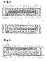
Fig. 2 is a vertical cross-sectional view showing a power generation cell; -
Fig. 3 is a cross-sectional view taken along line 3-3 inFig. 2 ; -
Fig. 4 is an exploded perspective view illustrating first and second frames, an electrode structure, first and second gas passage forming members, porous layers, and drainage promoting members; -
Fig. 5 is a vertical cross-sectional view illustrating a fuel battery according to a second embodiment of the present invention; -
Fig. 6 is a vertical cross-sectional view illustrating a fuel battery according to a third embodiment of the present invention; -
Fig. 7 is a vertical cross-sectional view illustrating a prior art fuel battery; -
Fig. 8 is a partially enlarged cross-sectional view illustrating the fuel battery shown inFig. 7 ; -
Fig. 9 is a partial perspective view illustrating a gas passage forming member used in the fuel battery shown inFig. 7 ; -
Fig. 10 is a graph showing the relationship between a corrosion current and the potential on the anode side and the cathode side of a fuel battery; and -
Fig. 11 is a vertical cross-sectional view illustrating a prior art fuel battery. - A fuel battery according to a first embodiment of the present invention will be described with reference to
Figs. 1 to 4 . - As shown in
Fig. 2 , afuel cell stack 11 of the first embodiment is a solid polymer type, and is formed by a number of stackedpower generation cells 12. - As shown in
Fig. 4 , thepower generation cell 12 is shaped like a rectangular frame and includes first andsecond frames first frame 13 defines in it a passage space S1 for fuel gas, and thesecond frame 14 defines in it a passage space S2 for oxidation gas. TheMEA 15 is arranged between theframes Figs. 2 and 3 , thepower generation cell 12 has a first gaspassage forming member 21, which is formed by ferrite-based SUS (stainless steel) and is accommodated in the fuel gas passage space S1, and a second gaspassage forming member 22, which is made of titanium or gold and is accommodated in the oxidation gas passage space S2. Further, thepower generation cell 12 has afirst separator 23 and asecond separator 24, which are made of titanium. Thefirst separator 23 is shaped like a flat plate, and is bonded to the upper surfaces of thefirst frame 13 and the first gaspassage forming member 21 as viewed in the drawing. Thesecond separator 24 is bonded to the lower surfaces of theframe 14 and the second gaspassage forming member 22 as viewed in the drawing. InFig. 4 , the gaspassage forming members - As shown in
Figs. 2 and 3 , theMEA 15 is formed by anelectrolyte membrane 16, a firstelectrode catalyst layer 17, a secondelectrode catalyst layer 18, and conductive first and second gas diffusion layers 19, 20. The firstelectrode catalyst layer 17 is formed of catalyst that is laid on the anode-side surface of theelectrolyte membrane 16, that is, on the upper surface as viewed in the drawing. The secondelectrode catalyst layer 18 is formed of catalyst that is laid on the cathode-side surface of theelectrolyte membrane 16, that is, on the lower surface as viewed in the drawing. The gas diffusion layers 19, 20 are bonded to the surfaces of the electrode catalyst layers 17, 18, respectively. When the fuel battery of the present embodiment is used, theelectrode structure 15 of eachpower generation cell 12 in thefuel cell stack 11 shown inFig. 2 is parallel to the vertical direction. - The
solid electrolyte membrane 16 is formed of a fluoropolymer film. As shown inFig. 8 , which is described in the BACKGROUND ART, the electrode catalyst layers 17, 18 each havecarbon particles 51 supporting a platinum catalyst, and a great number of platinum (Pt)catalyst particles 52 adhere to the surface of eachcarbon particle 51. The electrode catalyst layers 17, 18 are bonded to thesolid electrolyte membrane 16 by paste for forming an electrode catalyst layer. Thecatalyst particles 52 serving as catalyst increase the power generation efficiency when power is generated by the fuel battery. In the present embodiment, the diameter of thecarbon particles 51 is several micrometers, and the diameters of thecatalyst particles 52 is 2 nm. The gas diffusion layers 19, 20 are formed of carbon paper. - The first gas
passage forming member 21 located on the anode side and the second gaspassage forming member 22 located on the cathode side have similar structures. In the present embodiment, the gaspassage forming members Fig. 9 , which has been described in the BACKGROUND ART. - As shown in
Fig. 2 , a firstporous layer 25 is located between the first gaspassage forming member 21 and thefirst separator 23. The firstporous layer 25 is formed of conductive porous material having continuous pores. Likewise, a secondporous layer 26 is located between the second gaspassage forming member 22 and thesecond separator 23. The secondporous layer 26 is formed of conductive porous material having continuous pores. - As shown in
Fig. 4 , the fuel gas passage space S1 of thefirst frame 13 is shaped rectangular as viewed from above. Elongated fuelgas introducing port 13a and fuelgas discharging port 13b are formed in two parallel andopposite sides first frame 13. Theports gas introducing port 13c and oxidationgas discharging port 13d are formed in twosides frame 13, which are adjacent to thesides - The
second frame 14 has a similar structure as thefirst frame 13. Thesecond frame 14 has a fuelgas introducing port 14a, a fuelgas discharging port 14b, an oxidationgas introducing port 14c, and an oxidationgas discharging port 14d, which correspond to the fuelgas introducing port 13a, the fuelgas discharging port 13b, the oxidationgas introducing port 13c, and the oxidationgas discharging port 13d of theframe 13, respectively. - A fuel
gas introducing port 23a, a fuelgas discharging port 23b, an oxidationgas introducing port 23c, and an oxidationgas discharging port 23d are formed in the four sides of thefirst separator 23 to correspond to the fuelgas introducing port 13a, the fuelgas discharging port 13b, the oxidationgas introducing port 13c, and the oxidationgas discharging port 13d formed in thefirst frame 13, respectively. Likewise, a fuelgas introducing port 24a, a fuelgas discharging port 24b, an oxidation gas introducing port 24c, and an oxidationgas discharging port 24d are formed in the four sides of thesecond separator 24 to correspond to the fuelgas introducing port 14a, the fuelgas discharging port 14b, the oxidationgas introducing port 14c, and the oxidationgas discharging port 14d formed in thesecond frame 14, respectively. - In the fuel gas passage space S1 (the oxidation gas passage space S2) of the first (second)
frame 13, the first, second gas passage forming member 21 (22) contacts the front surfaces of the gas diffusion layer 19 (20) and the back surface of the first (second) porous layer 25 (26), as shown inFig. 1 . - As shown in
Figs. 3 and4 , the fuelgas introducing port 23a of thefirst separator 23, the fuelgas introducing port 13a of theframe 13, the fuelgas introducing port 14a of thesecond frame 14, and the fuelgas introducing port 24a of thesecond separator 24 form a supply passage M1 for supplying fuel gas to eachpower generation cell 12. The fuelgas discharging port 23b of thefirst separator 23, the fuelgas discharging port 13b of thefirst frame 13, the fuelgas discharging port 14b of thesecond frame 14, the fuelgas discharging port 23b of theseparator 23, and the fuelgas discharging port 24b of thesecond separator 24 form a fuel off-gas discharging passage M2 through eachpower generation cell 12. Fuel gas that is supplied to the fuel gas supply passage M1 from the outside of the fuel battery passes through a gas passage T1 of the first gaspassage forming member 21 and is used for generating power. Thereafter, the fuel gas is drawn to the discharging passage M2 as fuel off-gas. - The oxidation
gas introducing port 23c of thefirst separator 23, the oxidationgas introducing port 13c of theframe 13, the oxidationgas introducing port 14c of thesecond frame 14, and the oxidation gas introducing port 24c of thesecond separator 24 form a supply passage R1 for supplying oxidation gas to eachpower generation cell 12. The oxidationgas discharging port 23d of thefirst separator 23, the oxidationgas discharging port 13d of theframe 13, the oxidationgas discharging port 14d of thesecond frame 14, and the oxidationgas discharging port 24d of thesecond separator 24 form a discharging passage R2 for discharging oxidation off-gas from eachpower generation cell 12. Oxidation gas that is supplied to the oxidation gas supply passage R1 from the outside of the fuel battery passes through a gas passage T2 of the second gaspassage forming member 22 and is used for generating power. Thereafter, the oxidation gas is drawn into the discharging passage R2 as oxidation off-gas. - As shown in
Fig. 3 , an upstream portion of the passage space S1 formed in the first gaspassage forming member 21 communicates with the fuelgas introducing port 13a of thefirst frame 13, and a downstream portion of the passage spaced S1 communicates with the fuelgas discharging port 13b of thefirst frame 13. A downstream space in the passage space S1 forms acommunication passage 27 where the first gaspassage forming member 21 or the firstporous layer 25 does not exist. Adrainage promoting member 28 is provided in thecommunication passage 27. Thedrainage promoting member 28 is formed of a porous material having continuous pores, such as urethane sponge or the surface of the sea. The downstream edge of the first gaspassage forming member 21 and the downstream edge of the continuous pores of the firstporous layer 25 contact thedrainage promoting member 28 over the entire area. The downstream end of the gas passage T1 of the first gaspassage forming member 21 communicates with continuous pores of thedrainage promoting member 28, the downstream end of continuous pores of the firstporous layer 25 also communicates with continuous pores of thedrainage promoting member 28. - As shown in
Fig. 2 , an upstream portion of the passage space S2 formed in the second gaspassage forming member 22 communicates with the fuelgas introducing port 14a of thesecond frame 14, and a downstream portion of the passage spaced S2 communicates with the fuelgas discharging port 14b of thesecond frame 14. A downstream space in the passage space S2 forms acommunication passage 29 where the second gaspassage forming member 22 or the secondporous layer 26 does not exist. A seconddrainage promoting member 30 is provided in thecommunication passage 29. The seconddrainage promoting member 30 is formed of a porous material having continuous pores, such as urethane sponge or the surface of the sea. The downstream edge of the second gaspassage forming member 22 and the downstream edge of the continuous pores of the secondporous layer 26 contact the seconddrainage promoting member 30 over the entire area. The downstream end of the gas passage T2 of the second gaspassage forming member 22 communicates with continuous pores of thedrainage promoting member 30, the downstream end of continuous pores of the secondporous layer 26 also communicates with continuous pores of thedrainage promoting member 30. - The thicknesses of the first and second
porous layers porous layers porous layers drainage promoting members porous layer drainage promoting members - Operation of the fuel battery configured as above will now be described.
- In
Fig. 3 , fuel gas that is supplied to the fuel gas supply passage M1 forms turbulence when flowing along the direction of the arrow in the gas passage T1 of the first gaspassage forming member 21. The fuel gas is thus diffused in the gas passage T1. The fuel gas is further properly diffused by passing through the firstgas diffusion layer 19, so as to be evenly supplied to the firstelectrode catalyst layer 17. - In
Fig. 2 , oxidation gas that is supplied to the oxidation gas supply passage R1 forms turbulence when flowing along the direction of the arrow in the gas passage T2 of the second gaspassage forming member 22. The oxidation gas is thus diffused in the gas passage T2. The oxidation gas is further properly diffused by passing through the secondgas diffusion layer 20, so as to be evenly supplied to theelectrode catalyst layer 18. The supply of the fuel gas and the oxidation gas initiates an electrode reaction at theMEA 15, so that power is generated. Thefuel cell stack 11, which is formed by the stackedpower generation cells 12, thus outputs a desired power. - During such a power generating state, water is generated in the gas passage T2 of the cathode-side second gas
passage forming member 22, as described in the BACKGROUND ART. Some of the hydrogen gas is not used in power generation and is drained as fuel off-gas to the outside through the gas passage T1 of the first gaspassage forming member 21, the continuous pores of the firstdrainage promoting member 28, and the fuel gas discharging passage M2. Some of the oxygen gas that has not been oxidized during the power generation is conducted, together with nitrogen gas and generated water, to the oxidation gas discharging passage R2 formed in theframes drainage promoting member 30 and is drained as oxidation off-gas to the outside. Some of the generated water flows as seepage water into the gas passage T1 of the first gaspassage forming member 21, while seeping through the cathode-side secondelectrode catalyst layer 18, thesolid electrolyte membrane 16, the firstelectrode catalyst layer 17, and the firstgas diffusion layer 19. - When fuel gas flows through the gas passage T1 as indicated by the arrow in
Fig. 3 , seepage water contained in the fuel gas collects as droplets W on the wall of the gas passage T1. The droplets W (seepage water) are drawn into the continuous pores of the firstporous layer 25 as shown inFig. 1(b) , by capillary action of the continuous pores of the firstporous layer 25. The fuel gas flowing through the gas passage T1 becomes fuel off-gas and passes through the continuous pores of the firstdrainage promoting member 28, and is then conducted into the fuel off-gas discharging passage M2. The droplets W (seepage water) drawn into the firstporous layer 25 are caused to flow downstream in the gas flowing direction P by the fluid pressure of fuel gas flowing through the gas passage T1, and then drawn into the continuous pores of the firstdrainage promoting member 28 by capillary action as shown inFig. 1(c) . The seepage water W drawn by the firstdrainage promoting member 28 is forced out by the fluid pressure of fuel off-gas passing through the continuous pores of the promotingmember 28. That is, the flow of fuel off-gas flowing through the continuous pores of the promotingmember 28 forces out the seepage water W, which has been drawn into the continuous pores of the promotingmember 28, by pressure difference. Accordingly, the pressure of the continuous pores of the promotingmember 28 becomes lower than the pressure of the continuous pores of the firstporous layer 25. This pressure difference draws the seepage water in the continuous pores of the firstporous layer 25 to the continuous pores in the promotingmember 28, so that the seepage water is drained into the fuel off-gas discharging passage M2. - Like the seepage water in the gas passage T1, water generated in the gas passage T2 in the cathode-side second gas
passage forming member 22 as shown inFig. 2 is drained into the oxidation off-gas discharging passage R2 by capillary action of the continuous pores of the cathode-side secondporous layer 26 and the seconddrainage promoting member 30, and the fluid pressure gas that flows through the continuous pores of the seconddrainage promoting member 30. - The fuel battery according to the first embodiment has the following advantages.
- (1) In the first embodiment, the first
porous layer 25 is located between the anode-side first gaspassage forming member 21 and theseparator 23, and the firstdrainage promoting member 28 is located in thecommunication passage 27 formed in a downstream portion of the passage space S1. Seepage water in the gas passage T1 formed in the first gaspassage forming member 21 is drawn into the firstporous layer 25 by capillary action of the first porous layer 2. The seepage water drawn into theporous layer 25 flows to the firstdrainage promoting member 28 by surface tension of water. Thereafter, as described above, the fluid pressure of fuel off-gas flowing through the promotingmember 28 allows the seepage water to be efficiently drawn from theporous layer 25 to thedrainage promoting member 28 and to be drained into the fuel off-gas discharging passage M2. Since this configuration properly supplies fuel gas to the firstelectrode catalyst layer 17, deficiency of oxidation gas is avoided, and power generation efficiency is improved. - Also, the seepage water in the gas passage T1 of the first gas
passage forming member 21 is drawn into the firstporous layer 25 and drained into the fuel off-gas discharging passage M2 via the firstdrainage promoting member 28. This prevents the seepage water from remaining in the gas passage T1, and the pressure loss of fuel gas flowing through the gas passage T1 due to seepage water is thus reduced. This improves power generation efficiency. Further, the potential of the anode-sideelectrode catalyst layer 17 is prevented from being increased by hydrogen deficiency, and corrosion of the first gaspassage forming member 21 due to increase in the potential is prevented. This improves durability. The selection criteria for the material of the first gaspassage forming member 21 are relaxed, so that inexpensive material can be used as the material for the first gaspassage forming member 21. This reduces material costs. In addition, since fuel deficiency is avoided in the anode-side firstelectrode catalyst layer 17, it is possible to prevent reduction of hydrated protons in theelectrolyte membrane 16 described in the BACKGROUND ART. Since reduction in the hydrated protons is compensated for, erosion ofcarbon particles 51 in the cathode-sideelectrode catalyst layer 18 is prevented. This improves the durability of theelectrode catalyst layer 18. - (2) In the first embodiment, the second
porous layer 26 is located between the cathode-side second gaspassage forming member 22 and theseparator 24, and the seconddrainage promoting member 30 is provided in thecommunication passage 29 in a downstream portion of the passage space S2. Thus, water generated in the gas passage T2 in the cathode-side second gaspassage forming member 22 is drained into the oxidation off-gas discharging passage R2 by the second porous layer and the second drainage promoting member. This prevents the generated water from remaining in the gas passage T2 of the second gaspassage forming member 22, and the pressure loss of oxidation gas flowing through the gas passage T2 due to generated water is reduced. This improves power generation efficiency. Also, since this configuration properly supplies fuel gas to theelectrode catalyst layer 18, deficiency of oxidation gas is avoided, and power generation efficiency is improved. - (3) In the first embodiment, the first and second
porous layers drainage promoting members power generation cells 12 and thus to stabilize power generation performance of the fuel battery. For example, in a low load operating state of the fuel battery, the flow rate of gas flowing through the gas passages T1, T2 of the gaspassage forming members power generation cells 12 is properly performed, so that variations in the power generation output of thecells 12 are eliminated. This improves battery performance. In a high load operating state of the fuel battery, the amount of water generated in the gas passage T2 of the cathode-side second gaspassage forming member 22 is increased. As described above, the generated water is properly drained, so that oxidation gas is reliably diffused in the gas passage T2. This stabilizes power generation output. - A second embodiment according to the present invention will now be described with reference to
Fig. 5 . In the following embodiments, components having similar functions as those in the first embodiment are given the same reference numerals, and the descriptions thereof are omitted. Operations and advantages of components different from those in the first embodiment will mainly be discussed. - In the second embodiment, a second
drainage promoting member 30 that is formed of the same material as a cathode-side secondporous layer 26 is integrated with the downstream end of the secondporous layer 26. Although not illustrated, a firstdrainage promoting member 28 that is formed of the same material as an anode-side firstporous layer 25 is integrated with the downstream end of the firstporous layer 25. - In the second embodiment, since the first (second) porous layer 25 (26) and the first (second) drainage promoting member 28 (30) are formed integrally, seepage water (generated water) drawn into the first (second) porous layer 25 (26) smoothly flows to the first (second) drainage promoting member 28 (30), and the water is further properly discharged.
- In a third embodiment, a
drain port 35 is formed in a cathode-side separator 24 as shown inFig. 6 . A communication passage 36 for oxidation off-gas and generated water is formed between theseparator 24 and an anode-side separator 23 of an adjacent power generation cell. The communication passage 36 communicates with thedrain port 35. A seconddrainage promoting member 30, which is formed of the same material as a secondporous layer 26 and is integrated with the secondporous layer 26 is accommodated in thedrain port 35. Although not illustrated, the configuration on the anode side is the same as that on the cathode side. - This configuration allows oxidation gas and generated water to be conducted into the oxidation off-gas discharging passage R2 by the second
drainage promoting member 30 provided in thedrain port 35. - The present invention may be modified according to the embodiments described below.
- Although not illustrated, a
porous layer 25 and adrainage promoting member 28 may be provided only on the anode side in each of the illustrated embodiments. This configuration not only improves power generation efficiency of the fuel battery, but also improves durability of the anode-side second gaspassage forming member 22 and the cathode-sideelectrode catalyst layer 18. Also aporous layer 26 and adrainage promoting member 30 may be provided only on the cathode side. This configuration improves power generation efficiency of the fuel battery. - In the first or second embodiment, the average pore diameter of the continuous pores of the
drainage promoting member 30 is set to be smaller than or equal to the average pore diameter of the continuous pores of theporous layers porous layers drainage promoting member 30 by capillary action. Instead, the wettability of the continuous pores of thedrainage promoting member 30 may be set greater than the wettability of the continuous pores of theporous layers drainage promoting member 30 may be set greater than the droplet contact angle of the continuous pores of theporous layers drainage promoting member 30 may be set better the hydration property of the continuous pores of theporous layer drainage promoting member 30 is set greater than the average pore diameter of the continuous pores of theporous layers porous layer drainage promoting member 30. - In the fuel battery of each of the illustrated embodiments, grooves for conducting coolant water may be formed in the
separators power generation cells 12. - The gas diffusion layers 19, 20 may be omitted from the fuel batteries of the above illustrated embodiments.
- In a fuel battery in which the
porous layer 26 is provided only on the cathode side, the anode side first gaspassage forming member 21 and thefirst separator 23 may be integrally formed. Theframe 13 and thefirst separator 23 may be integrally formed of metal, for example, by forging. - In a fuel battery in which the
porous layer 25 is provided only on the anode side, the cathode side second gaspassage forming member 22 and thesecond separator 24 may be integrally formed. Theframe 14 and thesecond separator 24 may be integrally formed of metal, for example, by forging.
Claims (9)
- A fuel battery comprising:a first electrode catalyst layer laid on an anode-side surface of an electrolyte membrane;a second electrode catalyst layer laid on a cathode-side surface of the electrolyte membrane;a first gas passage forming member laid on a front surface of the first electrode catalyst layer, the first gas passage forming member having a first gas passage for supplying fuel gas;a second gas passage forming member laid on a front surface of the second electrode catalyst layer, the second gas passage forming member having a second gas passage for supplying oxidation gas;a first separator provided in the first gas passage forming member;a second separator laid on a front surface of the second gas passage forming member;an introducing passage and a discharging passage for the fuel gas; andan introducing passage and a discharging passage for the oxidation gas,the fuel battery being characterized in that:a porous layer is located between the front surface of the second gas passage forming member and a back surface of the second separator that corresponds to the second gas passage forming member, the porous layer having continuous pores for drawing in water from the second gas passage by capillary action;a drainage promoting member formed of a porous material having continuous pores is provided to communicate with a downstream end of the second gas passage of the second gas passage forming member and to communicate with a downstream end of the continuous pores of the porous layer, andwater drawn from the second gas passage to the porous layer by capillary action flows downstream by surface tension of water and is then drawn in by the continuous pores of the drainage promoting member, and water in the drainage promoting member is discharged into the discharging passage by fluid pressure of oxidation off-gas that flows from the second gas passage to the continuous pores of the drainage promoting member.
- The fuel battery according to claim 1, characterized in that the average pore diameter of the continuous pores of the drainage promoting member is set less than or equal to the average pore diameter of the continuous pores of the porous layer.
- The fuel battery according to claim 1 or 2, characterized in that the drainage promoting member is formed integrally of the same material as the porous layer.
- The fuel battery according to claim 1, characterized in that one of the following structures is selected: a structure in which the average pore diameter of the continuous pores of the drainage promoting member is set shallower than the depth of a water passage; a structure in which the wettability of the continuous pores of the drainage promoting member is set higher than the wettability of the water passage; and a structure in which the hydration property of the continuous pores of the drainage promoting member is set higher than the hydration property of the water passage.
- A fuel battery comprising:a first electrode catalyst layer laid on an anode-side surface of an electrolyte membrane;a second electrode catalyst layer laid on a cathode-side surface of the electrolyte membrane;a first gas passage forming member laid on a front surface of the first electrode catalyst layer, the first gas passage forming member having a first gas passage for supplying fuel gas;a second gas passage forming member laid on a front surface of the second electrode catalyst layer, the second gas passage forming member having a second gas passage for supplying oxidation gas;a first separator laid on a front surface of the first gas passage forming member;a second separator provided in the second gas passage forming member;an introducing passage and a discharging passage for the fuel gas; andan introducing passage and a discharging passage for the oxidation gas,the fuel battery being characterized in that:a first porous layer is located between the front surface of the first gas passage forming member and a back surface of the first separator that corresponds to the first gas passage forming member, the first porous layer having continuous pores for drawing in water from the first gas passage by capillary action;a first drainage promoting member formed of a porous material having continuous pores is provided to communicate with a downstream end of the first gas passage of the first gas passage forming member and to communicate with a downstream end of the continuous pores of the porous layer, andwater drawn from the first gas passage to the first porous layer by capillary action flows downstream by fluid pressure of fuel gas flowing through the first gas passage and is then drawn in by the continuous pores of the first drainage promoting member, and water in the first drainage promoting member is discharged into the discharging passage by fluid pressure of fuel off-gas that flows from the first gas passage into the continuous pores of the first drainage promoting member.
- The fuel battery according to claim 5, characterized in that:a second porous layer is located between the front surface of the second gas passage forming member and a back surface of the second separator that corresponds to the second gas passage forming member, the second porous layer having continuous pores for drawing in water from the second gas passage by capillary action;a second drainage promoting member formed of a porous material having continuous pores is provided to communicate with a downstream end of the second gas passage of the second gas passage forming member and to communicate with a downstream end of the continuous pores of the second porous layer, andwater drawn from the second gas passage to the second porous layer by capillary action flows downstream by surface tension of water and is then drawn in by the continuous pores of the second drainage promoting member, and water in the drainage promoting member is discharged into the discharging passage by fluid pressure of oxidation off-gas that flows from the second gas passage into the continuous pores of the drainage promoting member.
- The fuel battery according to claim 5 or 6, characterized in that the average pore diameter of the continuous pores of the drainage promoting member is set less than or equal to the average pore diameter of the continuous pores of the porous layer.
- The fuel battery according to claim 5 or 6, characterized in that the drainage promoting member is formed integrally of the same material as the porous layer.
- The fuel battery according to claim 5, characterized in that one of the following structures is selected: a structure in which the average pore diameter of the continuous pores of the drainage promoting member is set shallower than the depth of a water passage; a structure in which the wettability of the continuous pores of the drainage promoting member is set higher than the wettability of the water passage; and a structure in which the hydration property of the continuous pores of the drainage promoting member is set higher than the hydration property of the water passage.
Applications Claiming Priority (1)
| Application Number | Priority Date | Filing Date | Title |
|---|---|---|---|
| PCT/JP2009/056692 WO2010113277A1 (en) | 2009-03-31 | 2009-03-31 | Fuel battery |
Publications (3)
| Publication Number | Publication Date |
|---|---|
| EP2416415A1 true EP2416415A1 (en) | 2012-02-08 |
| EP2416415A4 EP2416415A4 (en) | 2016-07-06 |
| EP2416415B1 EP2416415B1 (en) | 2018-05-09 |
Family
ID=42827610
Family Applications (1)
| Application Number | Title | Priority Date | Filing Date |
|---|---|---|---|
| EP09842631.5A Not-in-force EP2416415B1 (en) | 2009-03-31 | 2009-03-31 | Fuel battery |
Country Status (5)
| Country | Link |
|---|---|
| US (1) | US8835064B2 (en) |
| EP (1) | EP2416415B1 (en) |
| JP (1) | JP5246329B2 (en) |
| CN (1) | CN102405547B (en) |
| WO (1) | WO2010113277A1 (en) |
Families Citing this family (4)
| Publication number | Priority date | Publication date | Assignee | Title |
|---|---|---|---|---|
| JP6233220B2 (en) * | 2014-07-15 | 2017-11-22 | トヨタ車体株式会社 | Fuel cell |
| CN106602107A (en) * | 2016-12-21 | 2017-04-26 | 武汉理工大学 | Active water-draining type fuel cell |
| KR102829315B1 (en) * | 2019-05-10 | 2025-07-02 | 현대자동차주식회사 | Fuel cell apparatus |
| CN111785987A (en) * | 2020-07-29 | 2020-10-16 | 杭州祥博传热科技股份有限公司 | Flow field cooling device for bipolar plate |
Family Cites Families (13)
| Publication number | Priority date | Publication date | Assignee | Title |
|---|---|---|---|---|
| JP3524305B2 (en) * | 1996-12-03 | 2004-05-10 | 本田技研工業株式会社 | Fuel cell |
| JP4610815B2 (en) * | 2001-09-14 | 2011-01-12 | 東芝燃料電池システム株式会社 | Polymer electrolyte fuel cell |
| JP4432518B2 (en) | 2003-10-27 | 2010-03-17 | トヨタ自動車株式会社 | Fuel cell system |
| US20070196711A1 (en) | 2004-03-15 | 2007-08-23 | Shinsuke Takeguchi | Polymer Electrolyte Fuel Cell |
| JP4923387B2 (en) * | 2004-04-16 | 2012-04-25 | トヨタ自動車株式会社 | Fuel cell with porous separator |
| JP2006004803A (en) * | 2004-06-18 | 2006-01-05 | Toyota Motor Corp | Fuel cell |
| JP2006079982A (en) * | 2004-09-10 | 2006-03-23 | Nissan Motor Co Ltd | Fuel cell |
| JP2006269160A (en) * | 2005-03-23 | 2006-10-05 | Nissan Motor Co Ltd | Fuel cell |
| JP4815916B2 (en) * | 2005-07-21 | 2011-11-16 | 株式会社エクォス・リサーチ | Fuel cell and fuel cell system |
| JP2007059328A (en) | 2005-08-26 | 2007-03-08 | Canon Inc | Fuel cell and electronic equipment |
| JP4915070B2 (en) | 2005-09-22 | 2012-04-11 | トヨタ車体株式会社 | Fuel cell separator |
| JP2007311089A (en) | 2006-05-17 | 2007-11-29 | Hitachi Ltd | Fuel cell separator |
| JP4375480B2 (en) * | 2007-12-25 | 2009-12-02 | アイシン精機株式会社 | Polymer electrolyte fuel cell |
-
2009
- 2009-03-31 JP JP2011506898A patent/JP5246329B2/en active Active
- 2009-03-31 WO PCT/JP2009/056692 patent/WO2010113277A1/en not_active Ceased
- 2009-03-31 EP EP09842631.5A patent/EP2416415B1/en not_active Not-in-force
- 2009-03-31 US US13/146,799 patent/US8835064B2/en active Active
- 2009-03-31 CN CN200980155939.2A patent/CN102405547B/en not_active Expired - Fee Related
Non-Patent Citations (1)
| Title |
|---|
| See references of WO2010113277A1 * |
Also Published As
| Publication number | Publication date |
|---|---|
| JP5246329B2 (en) | 2013-07-24 |
| CN102405547B (en) | 2015-04-22 |
| WO2010113277A1 (en) | 2010-10-07 |
| CN102405547A (en) | 2012-04-04 |
| EP2416415B1 (en) | 2018-05-09 |
| US8835064B2 (en) | 2014-09-16 |
| JPWO2010113277A1 (en) | 2012-10-04 |
| US20120009489A1 (en) | 2012-01-12 |
| EP2416415A4 (en) | 2016-07-06 |
Similar Documents
| Publication | Publication Date | Title |
|---|---|---|
| WO2010113252A1 (en) | Fuel battery | |
| US9065090B2 (en) | Fuel battery | |
| US9553324B2 (en) | Fuel cell resin frame equipped membrane electrode assembly | |
| EP2876715B1 (en) | Fuel cell | |
| CN102479965B (en) | Fuel cell | |
| US9214682B2 (en) | Fuel cell | |
| JP6477412B2 (en) | Fuel cell | |
| KR20140084247A (en) | Flow battery with mixed flow | |
| US8445160B2 (en) | Fuel cell with gas passage forming member and water ingression preventing means | |
| CN111509254A (en) | Separator for fuel cell | |
| EP2416415B1 (en) | Fuel battery | |
| JP2010153175A (en) | Fuel battery | |
| JP5274908B2 (en) | Fuel cell stack | |
| JP5125022B2 (en) | Fuel cell | |
| CN102130353A (en) | Solid high-polymer fuel cell | |
| KR20200057512A (en) | Fuel cell stack | |
| JP5246331B2 (en) | Fuel cell | |
| EP3050146B1 (en) | Fuel cell | |
| JP5074724B2 (en) | Fuel cell | |
| CN102214832B (en) | Fuel cell | |
| JP2010003531A (en) | Fuel cell stack | |
| JP2023124379A (en) | fuel cell | |
| JP2006066092A (en) | Separator and fuel cell stack | |
| JP2009093889A (en) | Fuel cell |
Legal Events
| Date | Code | Title | Description |
|---|---|---|---|
| PUAI | Public reference made under article 153(3) epc to a published international application that has entered the european phase |
Free format text: ORIGINAL CODE: 0009012 |
|
| 17P | Request for examination filed |
Effective date: 20110726 |
|
| AK | Designated contracting states |
Kind code of ref document: A1 Designated state(s): AT BE BG CH CY CZ DE DK EE ES FI FR GB GR HR HU IE IS IT LI LT LU LV MC MK MT NL NO PL PT RO SE SI SK TR |
|
| DAX | Request for extension of the european patent (deleted) | ||
| RA4 | Supplementary search report drawn up and despatched (corrected) |
Effective date: 20160606 |
|
| RIC1 | Information provided on ipc code assigned before grant |
Ipc: H01M 8/0241 20160101AFI20160531BHEP Ipc: H01M 8/0247 20160101ALI20160531BHEP Ipc: H01M 8/04291 20160101ALI20160531BHEP Ipc: H01M 8/1004 20160101ALI20160531BHEP |
|
| STAA | Information on the status of an ep patent application or granted ep patent |
Free format text: STATUS: EXAMINATION IS IN PROGRESS |
|
| 17Q | First examination report despatched |
Effective date: 20170214 |
|
| REG | Reference to a national code |
Ref country code: DE Ref legal event code: R079 Ref document number: 602009052265 Country of ref document: DE Free format text: PREVIOUS MAIN CLASS: H01M0008040000 Ipc: H01M0008024100 |
|
| GRAP | Despatch of communication of intention to grant a patent |
Free format text: ORIGINAL CODE: EPIDOSNIGR1 |
|
| STAA | Information on the status of an ep patent application or granted ep patent |
Free format text: STATUS: GRANT OF PATENT IS INTENDED |
|
| RIC1 | Information provided on ipc code assigned before grant |
Ipc: H01M 8/04291 20160101ALI20171109BHEP Ipc: H01M 8/1004 20160101ALI20171109BHEP Ipc: H01M 8/0241 20160101AFI20171109BHEP Ipc: H01M 8/0247 20160101ALI20171109BHEP |
|
| INTG | Intention to grant announced |
Effective date: 20171122 |
|
| GRAS | Grant fee paid |
Free format text: ORIGINAL CODE: EPIDOSNIGR3 |
|
| GRAA | (expected) grant |
Free format text: ORIGINAL CODE: 0009210 |
|
| STAA | Information on the status of an ep patent application or granted ep patent |
Free format text: STATUS: THE PATENT HAS BEEN GRANTED |
|
| AK | Designated contracting states |
Kind code of ref document: B1 Designated state(s): AT BE BG CH CY CZ DE DK EE ES FI FR GB GR HR HU IE IS IT LI LT LU LV MC MK MT NL NO PL PT RO SE SI SK TR |
|
| REG | Reference to a national code |
Ref country code: GB Ref legal event code: FG4D |
|
| REG | Reference to a national code |
Ref country code: CH Ref legal event code: EP Ref country code: AT Ref legal event code: REF Ref document number: 998333 Country of ref document: AT Kind code of ref document: T Effective date: 20180515 |
|
| REG | Reference to a national code |
Ref country code: IE Ref legal event code: FG4D |
|
| REG | Reference to a national code |
Ref country code: DE Ref legal event code: R096 Ref document number: 602009052265 Country of ref document: DE |
|
| REG | Reference to a national code |
Ref country code: NL Ref legal event code: MP Effective date: 20180509 |
|
| REG | Reference to a national code |
Ref country code: LT Ref legal event code: MG4D |
|
| PG25 | Lapsed in a contracting state [announced via postgrant information from national office to epo] |
Ref country code: SE Free format text: LAPSE BECAUSE OF FAILURE TO SUBMIT A TRANSLATION OF THE DESCRIPTION OR TO PAY THE FEE WITHIN THE PRESCRIBED TIME-LIMIT Effective date: 20180509 Ref country code: LT Free format text: LAPSE BECAUSE OF FAILURE TO SUBMIT A TRANSLATION OF THE DESCRIPTION OR TO PAY THE FEE WITHIN THE PRESCRIBED TIME-LIMIT Effective date: 20180509 Ref country code: ES Free format text: LAPSE BECAUSE OF FAILURE TO SUBMIT A TRANSLATION OF THE DESCRIPTION OR TO PAY THE FEE WITHIN THE PRESCRIBED TIME-LIMIT Effective date: 20180509 Ref country code: NO Free format text: LAPSE BECAUSE OF FAILURE TO SUBMIT A TRANSLATION OF THE DESCRIPTION OR TO PAY THE FEE WITHIN THE PRESCRIBED TIME-LIMIT Effective date: 20180809 Ref country code: FI Free format text: LAPSE BECAUSE OF FAILURE TO SUBMIT A TRANSLATION OF THE DESCRIPTION OR TO PAY THE FEE WITHIN THE PRESCRIBED TIME-LIMIT Effective date: 20180509 Ref country code: BG Free format text: LAPSE BECAUSE OF FAILURE TO SUBMIT A TRANSLATION OF THE DESCRIPTION OR TO PAY THE FEE WITHIN THE PRESCRIBED TIME-LIMIT Effective date: 20180809 |
|
| PG25 | Lapsed in a contracting state [announced via postgrant information from national office to epo] |
Ref country code: GR Free format text: LAPSE BECAUSE OF FAILURE TO SUBMIT A TRANSLATION OF THE DESCRIPTION OR TO PAY THE FEE WITHIN THE PRESCRIBED TIME-LIMIT Effective date: 20180810 Ref country code: NL Free format text: LAPSE BECAUSE OF FAILURE TO SUBMIT A TRANSLATION OF THE DESCRIPTION OR TO PAY THE FEE WITHIN THE PRESCRIBED TIME-LIMIT Effective date: 20180509 Ref country code: HR Free format text: LAPSE BECAUSE OF FAILURE TO SUBMIT A TRANSLATION OF THE DESCRIPTION OR TO PAY THE FEE WITHIN THE PRESCRIBED TIME-LIMIT Effective date: 20180509 Ref country code: LV Free format text: LAPSE BECAUSE OF FAILURE TO SUBMIT A TRANSLATION OF THE DESCRIPTION OR TO PAY THE FEE WITHIN THE PRESCRIBED TIME-LIMIT Effective date: 20180509 |
|
| REG | Reference to a national code |
Ref country code: AT Ref legal event code: MK05 Ref document number: 998333 Country of ref document: AT Kind code of ref document: T Effective date: 20180509 |
|
| PG25 | Lapsed in a contracting state [announced via postgrant information from national office to epo] |
Ref country code: CZ Free format text: LAPSE BECAUSE OF FAILURE TO SUBMIT A TRANSLATION OF THE DESCRIPTION OR TO PAY THE FEE WITHIN THE PRESCRIBED TIME-LIMIT Effective date: 20180509 Ref country code: DK Free format text: LAPSE BECAUSE OF FAILURE TO SUBMIT A TRANSLATION OF THE DESCRIPTION OR TO PAY THE FEE WITHIN THE PRESCRIBED TIME-LIMIT Effective date: 20180509 Ref country code: AT Free format text: LAPSE BECAUSE OF FAILURE TO SUBMIT A TRANSLATION OF THE DESCRIPTION OR TO PAY THE FEE WITHIN THE PRESCRIBED TIME-LIMIT Effective date: 20180509 Ref country code: EE Free format text: LAPSE BECAUSE OF FAILURE TO SUBMIT A TRANSLATION OF THE DESCRIPTION OR TO PAY THE FEE WITHIN THE PRESCRIBED TIME-LIMIT Effective date: 20180509 Ref country code: SK Free format text: LAPSE BECAUSE OF FAILURE TO SUBMIT A TRANSLATION OF THE DESCRIPTION OR TO PAY THE FEE WITHIN THE PRESCRIBED TIME-LIMIT Effective date: 20180509 Ref country code: RO Free format text: LAPSE BECAUSE OF FAILURE TO SUBMIT A TRANSLATION OF THE DESCRIPTION OR TO PAY THE FEE WITHIN THE PRESCRIBED TIME-LIMIT Effective date: 20180509 Ref country code: PL Free format text: LAPSE BECAUSE OF FAILURE TO SUBMIT A TRANSLATION OF THE DESCRIPTION OR TO PAY THE FEE WITHIN THE PRESCRIBED TIME-LIMIT Effective date: 20180509 |
|
| REG | Reference to a national code |
Ref country code: DE Ref legal event code: R097 Ref document number: 602009052265 Country of ref document: DE |
|
| PG25 | Lapsed in a contracting state [announced via postgrant information from national office to epo] |
Ref country code: IT Free format text: LAPSE BECAUSE OF FAILURE TO SUBMIT A TRANSLATION OF THE DESCRIPTION OR TO PAY THE FEE WITHIN THE PRESCRIBED TIME-LIMIT Effective date: 20180509 |
|
| PLBE | No opposition filed within time limit |
Free format text: ORIGINAL CODE: 0009261 |
|
| STAA | Information on the status of an ep patent application or granted ep patent |
Free format text: STATUS: NO OPPOSITION FILED WITHIN TIME LIMIT |
|
| 26N | No opposition filed |
Effective date: 20190212 |
|
| PG25 | Lapsed in a contracting state [announced via postgrant information from national office to epo] |
Ref country code: SI Free format text: LAPSE BECAUSE OF FAILURE TO SUBMIT A TRANSLATION OF THE DESCRIPTION OR TO PAY THE FEE WITHIN THE PRESCRIBED TIME-LIMIT Effective date: 20180509 |
|
| PG25 | Lapsed in a contracting state [announced via postgrant information from national office to epo] |
Ref country code: MC Free format text: LAPSE BECAUSE OF FAILURE TO SUBMIT A TRANSLATION OF THE DESCRIPTION OR TO PAY THE FEE WITHIN THE PRESCRIBED TIME-LIMIT Effective date: 20180509 |
|
| REG | Reference to a national code |
Ref country code: CH Ref legal event code: PL |
|
| PG25 | Lapsed in a contracting state [announced via postgrant information from national office to epo] |
Ref country code: LU Free format text: LAPSE BECAUSE OF NON-PAYMENT OF DUE FEES Effective date: 20190331 |
|
| REG | Reference to a national code |
Ref country code: BE Ref legal event code: MM Effective date: 20190331 |
|
| PG25 | Lapsed in a contracting state [announced via postgrant information from national office to epo] |
Ref country code: CH Free format text: LAPSE BECAUSE OF NON-PAYMENT OF DUE FEES Effective date: 20190331 Ref country code: IE Free format text: LAPSE BECAUSE OF NON-PAYMENT OF DUE FEES Effective date: 20190331 Ref country code: LI Free format text: LAPSE BECAUSE OF NON-PAYMENT OF DUE FEES Effective date: 20190331 |
|
| PG25 | Lapsed in a contracting state [announced via postgrant information from national office to epo] |
Ref country code: BE Free format text: LAPSE BECAUSE OF NON-PAYMENT OF DUE FEES Effective date: 20190331 |
|
| PG25 | Lapsed in a contracting state [announced via postgrant information from national office to epo] |
Ref country code: TR Free format text: LAPSE BECAUSE OF FAILURE TO SUBMIT A TRANSLATION OF THE DESCRIPTION OR TO PAY THE FEE WITHIN THE PRESCRIBED TIME-LIMIT Effective date: 20180509 |
|
| PGFP | Annual fee paid to national office [announced via postgrant information from national office to epo] |
Ref country code: GB Payment date: 20200318 Year of fee payment: 12 Ref country code: DE Payment date: 20200317 Year of fee payment: 12 |
|
| PG25 | Lapsed in a contracting state [announced via postgrant information from national office to epo] |
Ref country code: PT Free format text: LAPSE BECAUSE OF FAILURE TO SUBMIT A TRANSLATION OF THE DESCRIPTION OR TO PAY THE FEE WITHIN THE PRESCRIBED TIME-LIMIT Effective date: 20180910 Ref country code: MT Free format text: LAPSE BECAUSE OF NON-PAYMENT OF DUE FEES Effective date: 20190331 |
|
| PGFP | Annual fee paid to national office [announced via postgrant information from national office to epo] |
Ref country code: FR Payment date: 20200214 Year of fee payment: 12 |
|
| PG25 | Lapsed in a contracting state [announced via postgrant information from national office to epo] |
Ref country code: CY Free format text: LAPSE BECAUSE OF FAILURE TO SUBMIT A TRANSLATION OF THE DESCRIPTION OR TO PAY THE FEE WITHIN THE PRESCRIBED TIME-LIMIT Effective date: 20180509 |
|
| PG25 | Lapsed in a contracting state [announced via postgrant information from national office to epo] |
Ref country code: IS Free format text: LAPSE BECAUSE OF FAILURE TO SUBMIT A TRANSLATION OF THE DESCRIPTION OR TO PAY THE FEE WITHIN THE PRESCRIBED TIME-LIMIT Effective date: 20180909 |
|
| PG25 | Lapsed in a contracting state [announced via postgrant information from national office to epo] |
Ref country code: HU Free format text: LAPSE BECAUSE OF FAILURE TO SUBMIT A TRANSLATION OF THE DESCRIPTION OR TO PAY THE FEE WITHIN THE PRESCRIBED TIME-LIMIT; INVALID AB INITIO Effective date: 20090331 |
|
| REG | Reference to a national code |
Ref country code: DE Ref legal event code: R119 Ref document number: 602009052265 Country of ref document: DE |
|
| GBPC | Gb: european patent ceased through non-payment of renewal fee |
Effective date: 20210331 |
|
| PG25 | Lapsed in a contracting state [announced via postgrant information from national office to epo] |
Ref country code: DE Free format text: LAPSE BECAUSE OF NON-PAYMENT OF DUE FEES Effective date: 20211001 Ref country code: GB Free format text: LAPSE BECAUSE OF NON-PAYMENT OF DUE FEES Effective date: 20210331 Ref country code: FR Free format text: LAPSE BECAUSE OF NON-PAYMENT OF DUE FEES Effective date: 20210331 |
|
| PG25 | Lapsed in a contracting state [announced via postgrant information from national office to epo] |
Ref country code: MK Free format text: LAPSE BECAUSE OF FAILURE TO SUBMIT A TRANSLATION OF THE DESCRIPTION OR TO PAY THE FEE WITHIN THE PRESCRIBED TIME-LIMIT Effective date: 20180509 |