EP2416299A2 - A smoke alarm with protection mechanism - Google Patents
A smoke alarm with protection mechanism Download PDFInfo
- Publication number
- EP2416299A2 EP2416299A2 EP11006385A EP11006385A EP2416299A2 EP 2416299 A2 EP2416299 A2 EP 2416299A2 EP 11006385 A EP11006385 A EP 11006385A EP 11006385 A EP11006385 A EP 11006385A EP 2416299 A2 EP2416299 A2 EP 2416299A2
- Authority
- EP
- European Patent Office
- Prior art keywords
- housing
- battery compartment
- smoke alarm
- fastening cover
- lower arm
- Prior art date
- Legal status (The legal status is an assumption and is not a legal conclusion. Google has not performed a legal analysis and makes no representation as to the accuracy of the status listed.)
- Withdrawn
Links
Images




Classifications
-
- G—PHYSICS
- G08—SIGNALLING
- G08B—SIGNALLING SYSTEMS, e.g. PERSONAL CALLING SYSTEMS; ORDER TELEGRAPHS; ALARM SYSTEMS
- G08B17/00—Fire alarms; Alarms responsive to explosion
- G08B17/10—Actuation by presence of smoke or gases, e.g. automatic alarm devices for analysing flowing fluid materials by the use of optical means
-
- G—PHYSICS
- G08—SIGNALLING
- G08B—SIGNALLING SYSTEMS, e.g. PERSONAL CALLING SYSTEMS; ORDER TELEGRAPHS; ALARM SYSTEMS
- G08B17/00—Fire alarms; Alarms responsive to explosion
- G08B17/10—Actuation by presence of smoke or gases, e.g. automatic alarm devices for analysing flowing fluid materials by the use of optical means
- G08B17/11—Actuation by presence of smoke or gases, e.g. automatic alarm devices for analysing flowing fluid materials by the use of optical means using an ionisation chamber for detecting smoke or gas
- G08B17/113—Constructional details
-
- G—PHYSICS
- G08—SIGNALLING
- G08B—SIGNALLING SYSTEMS, e.g. PERSONAL CALLING SYSTEMS; ORDER TELEGRAPHS; ALARM SYSTEMS
- G08B29/00—Checking or monitoring of signalling or alarm systems; Prevention or correction of operating errors, e.g. preventing unauthorised operation
- G08B29/18—Prevention or correction of operating errors
- G08B29/181—Prevention or correction of operating errors due to failing power supply
-
- H—ELECTRICITY
- H01—ELECTRIC ELEMENTS
- H01M—PROCESSES OR MEANS, e.g. BATTERIES, FOR THE DIRECT CONVERSION OF CHEMICAL ENERGY INTO ELECTRICAL ENERGY
- H01M50/00—Constructional details or processes of manufacture of the non-active parts of electrochemical cells other than fuel cells, e.g. hybrid cells
- H01M50/20—Mountings; Secondary casings or frames; Racks, modules or packs; Suspension devices; Shock absorbers; Transport or carrying devices; Holders
- H01M50/204—Racks, modules or packs for multiple batteries or multiple cells
- H01M50/207—Racks, modules or packs for multiple batteries or multiple cells characterised by their shape
- H01M50/213—Racks, modules or packs for multiple batteries or multiple cells characterised by their shape adapted for cells having curved cross-section, e.g. round or elliptic
-
- Y—GENERAL TAGGING OF NEW TECHNOLOGICAL DEVELOPMENTS; GENERAL TAGGING OF CROSS-SECTIONAL TECHNOLOGIES SPANNING OVER SEVERAL SECTIONS OF THE IPC; TECHNICAL SUBJECTS COVERED BY FORMER USPC CROSS-REFERENCE ART COLLECTIONS [XRACs] AND DIGESTS
- Y02—TECHNOLOGIES OR APPLICATIONS FOR MITIGATION OR ADAPTATION AGAINST CLIMATE CHANGE
- Y02E—REDUCTION OF GREENHOUSE GAS [GHG] EMISSIONS, RELATED TO ENERGY GENERATION, TRANSMISSION OR DISTRIBUTION
- Y02E60/00—Enabling technologies; Technologies with a potential or indirect contribution to GHG emissions mitigation
- Y02E60/10—Energy storage using batteries
Definitions
- the invention relates to a smoke alarm provided with a protection mechanism.
- a smoke alarm comprising a housing with a battery compartment and a protection mechanism in the form of a flat spring extending to the battery compartment from its sidewall and bending at the top surface of the detector housing adjacent to the battery compartment.
- the part of the spring which is located on the top surface of the detector housing prevents the smoke alarm from being installed when the battery is not placed in the battery compartment.
- the protection mechanism is designed to be used with a rectangular battery. As the mechanism comprises only one spring located at the sidewall of the battery compartment and activated by pushing it to the sidewall, it cannot provide the same protection in the smoke alarm when more than one battery is needed.
- a smoke alarm with a protection mechanism which comprises a plastic plate provided in a battery compartment of the detector housing, in which battery is to be located.
- the plate is pushed up by a coil spring located below it and the plate has a pin attached to it from a top.
- the pin extends beyond the upper edge of the detector housing preventing the housing to be fastened to a fastening cover.
- the plastic plate Before placing a battery into the battery compartment, the plastic plate has to be pushed down against the spiral spring causing that the pin member moves to its lower position and allows the housing to be attached to the fastening cover.
- the known protection mechanism is very complex and susceptible to damages.
- the objective of the invention is to provide an improved smoke alarm which overcomes the above mentioned drawbacks of prior art.
- the objective of the invention is to provide an improved smoke alarm, which comprises a simple and reliable protection mechanism.
- the objective of the invention is to provide an improved smoke alarm, which prevents installation of the smoke alarm when at least one battery is missing from the required set of batteries.
- a smoke alarm comprising a housing having a top surface and delimiting a battery compartment having sidewalls and a bottom, in which at least one battery is placed; a fastening cover adapted to be mounted to a support and to be connected with the housing; and protection mechanism for preventing installation of the smoke alarm without a battery; characterized in that said protection mechanism comprises at least one spring member having at least one side arm and a lower arm, which is connected with the at least one side arm and located along and seated in the bottom of the battery compartment; wherein the lower arm is movable between the first position, when at least one battery is missing in the battery compartment, in which the connection region of the lower arm and the at least one side arm is located at distance from the bottom of the battery compartment and in which the at least one side arm protrude above the top surface of the housing and prevent attachment of the housing to the fastening cover and the second position, when all batteries are located in the battery compartment, in which the connection region of the lower arm and the at least one side arm is located adjacent to the bottom of the battery
- the at least one side arm is placed extending between the battery compartment and the top surface of the housing, in which the at least one side arm of the leaf spring can freely moved between the protruding and retracted positions.
- the side arm is placed in an open-ended path, which comprises slots formed between sidewalls and the bottom of the battery compartment, respectively, and openings extending between the slots and the top surface of the housing, respectively.
- the lower arm of the spring member is inclined upwards from the point, in which the lower arm is seated in the bottom of the battery compartment to its outer end, where the lower arm connects with the at least one side arm.
- the side arm is bended upwards from the lower arm approximately at right angle.
- the spring member is C-shaped and its lower arm extends laterally in the battery compartment being bending downwards at its center to form a protrusion and the bottom of the battery compartment has a recess, which receives the protrusion to seat the spring member in the battery compartment.
- the spring member is angular and it is placed with its side arm at one of the side walls of the battery compartment and soldered with its lower arm to the bottom of the battery compartment.
- At least two angular spring members are placed in the battery compartment being offset in relation to each other along the sidewalls the lower arm of each of them being soldered to the bottom in different points.
- the spring member is a sheet-metal spring or a wire spring.
- the top surface of the housing is provided with two catches extending upward and bending to opposite directions and the fastening cover is provided with apertures for receiving the catches and clamping them to the fastening cover by rotation movement of the housing in relation to the fastening cover.
- the fastening cover comprises holes, which are aligned with the openings when the housing is placed against the fastening cover, and the catches of the housing protrude through the apertures of the fastening cover; wherein the holes house portions of the side arms protruding through the openings to prevent rotation movement of the housing in relation to the fastening cover.
- the catches and the projections are lower than the upright peripheral wall of the fastening cover.
- the protection mechanism of the smoke alarm according to the present invention is very simple and reliable as it comprises only one member.
- the spring member of the mechanism When the spring member of the mechanism is not pressed by the batteries, which are located in the battery compartment, it prevents installation of the smoke alarm.
- the mechanism does not require any special actions to deactivate it. Simply inserting batteries into the battery compartment deactivates it.
- Smoke alarms are usually mounted to the ceiling.
- the words: upper, top, bottom, below, upwards, downwards, etc. determine position and directions in a smoke alarm, in which the fastening cover is mounted to the ceiling and the housing is attached to the fastening cover from below the fastening cover in the vertical direction.
- the smoke alarm 1 for detecting and alarming that there is smoke in case of fire is shown.
- the smoke alarm 1 comprises a housing 2, that is circular in the shown embodiment, and a fastening cover 3 adapted to be located on the top of the housing 2.
- the housing 2 has a bottom part 4 and annular sidewall 5 extended upwards above the bottom part 4.
- the housing 2 determines a cavity, in which all detecting smoke means are located (not shown).
- the top surface 6 of the housing 2 is lower in relation to the peripheral top edge of the annular sidewall 5 of the housing 2.
- the fastening cover 3 has an upright peripheral wall 3a and it is placed on the top surface 6 with upright peripheral wall 3a being flush with the annular sidewall 5 of the housing 2.
- the fastening cover 3 is provided with openings 7 for fixing the fastening cover 3 to a support, e.g. a ceiling, by a screws (not shown) before the housing 2 is attached to it.
- the fastening cover 3 has also a pair of rectangular apertures 8 with sloped snapping surfaces 8a, and the top surface 6 of the housing 2 is provided with two catches 9 extending upward and each bending to opposite direction for cooperating with the snapping surfaces 8a of the apertures 8 to connect the housing 2 to the fastening cover 3 by pressing and rotation movement of the housing 2 in relation to the fastening cover 3.
- the catches 9 extend from the housing top surface 6 for such distance that they protrude through apertures 8 in the fastening cover 3, when the housing 2 is attached to the fastening cover 3, but being still lower than the height of the fastening cover peripheral wall 3a. Shapes of the snapping surfaces 8a of the apertures 8 of the fastening cover 3 and the catches 7 of the housing 2 are such that they engage each other after rotation movement of the housing 2 in relation to the fastening cover 3 and fasten the housing 2 to the fastening cover 3 when the later has been fixed to the ceiling.
- the housing 2 has a battery compartment 10 for placing a set of batteries 11 necessary for proper function of the smoke alarm 1.
- the battery compartment 10 is provided with clamps 12 for fastening the batteries 11 and connectors 13 located at the both ends of the battery compartment 10 for connecting the batteries 11 with detecting/alarming means for supplying electric power.
- the battery compartment 10 has a rectangular shape having two opposite sidewalls 14,14a and a bottom 15.
- the battery compartment 10, the clamps 12 and the connectors 13 are designed to receive two cylindrical batteries 11, which are placed parallel to each other.
- a number of batteries 11 may be other than two.
- the housing 2 When the fastening cover 3 is fixed to a support, for example by a screw placed in the openings 7 and mounted in the support, and when the batteries 11 required for proper function of the smoke alarm 1 are already in place in the battery compartment 10, the housing 2 is attached to the fastening cover 3 by pushing the housing 2 against the fastening cover 3 in such way that the catches 9 are received in the apertures 8 and next by performing a rotation movement of the housing 2 in relation to the fixed fastening cover 3 which results in clamping the catches 9 on the snapping surfaces 8a of the apertures 8.
- a protection mechanism is provided in the battery compartment 10 of the smoke alarm 1 according to the invention. It is better seen in Fig. 2 , 3 and 5,6 the protection mechanism according to the invention comprises a spring member 17, which is seated in the bottom 15 of the battery compartment 10 and movable between the two positions in relation of the bottom 15 in vertical direction.
- the spring member 17 is in a C-formed flat sheet-metal spring having first and second side arms 17a, 17b with a lower arm 17c between them located laterally in the battery compartment 10.
- the lower arm 17c is bended downwards at its center to form a protrusion 17d and the bottom 15 of the battery compartment 10 has a recess 18, which receives the protrusion 17d to fix the position of the spring member 17 in relation to the battery compartment 10.
- the lower arm 17c of the spring member 17 is inclined upwards from the point, in which the lower arm 17c is seated in the bottom 15 of the battery compartment 10 to each of its outer ends, where the lower arm 17c connects with the side arms 17a,17b in a connection regions 17e.
- the first and second side arms 17a and 17b are bended upwards from the lower arm 17c, approximately at right angle.
- the spring member 17 is placed extending between the battery compartment 10 to the top surface 6 of the housing 2.
- the spring member 17 may be located in an open-ended channel comprising slots 19, 19a formed between sidewalls 14 and 14a and the bottom 15 of the battery compartment 10, respectively, and openings 20, 20a extending between the top surface 6 of the housing 2 and the slots 19, 19a, respectively.
- the size of the openings 20, 20a are adapted to place the side arms 17a,17b of the spring member 17 in them and allow the side arms 17a,17b to slide trough them freely.
- the lower arm 17c of the spring member 17 extends to and passes through the slots 19,19a and the side arms 17a,17b protrude through the openings 20,20a, respectively.
- the lower arm 17c of the spring member 17 When there is no battery 11 in the battery compartment 10 the lower arm 17c of the spring member 17 is in its first position, in which at least one of the connection regions 17e of the lower arm 17c and the side arms 17a, 17b is located at distance from the bottom 15 of the battery compartment 10 causing that the at least one of the side arms 17a,17b protrudes through the openings 20,20a above the top surface 6 of the housing 2 and prevent attachment of the housing 2 to the fastening cover 3. (see Figures 4 , 5 , 6 )
- the fastening cover 3 comprises holes 21, 21a, which are aligned with the ends of the spring member 17 seated in the battery compartment 10,when the housing 2 is placed against the fastening cover 3 and the catches 9 of the housing 2 protrude through the apertures 8 of the fastening cover 3.
- the holes 21,21a house the side arms ends protruding through the openings 20,20a above the top surface 6 of the housing 2 when there is insufficient number of batteries 11 in the battery compartment 10.
- holes 21,21 a The size of holes 21,21 a is designed in such way that interaction between the protruding side arms ends and the internal walls of the holes 21, 21 a blocks rotation movement of the housing 2 in relation to the fastening cover 3 that clamping the catches 9 of the housing 2 on the snapping surfaces 8a of the apertures 8 of the fastening cover 3 is prevented.. This protects the attachment of the housing 2 to the fastening cover 3 and installation of the smoke alarm 1 when the required batteries 11 are not in the place. As it is shown in Fig. 1 , 3 , 4 , 7 the holes 21,21 a may be covered by specially shaped part of the fastening cover 3.
- the predetermined number of batteries 11 must be put into the battery compartment 10, fastened by the clamps 12 and pressed against the connectors 13.
- FIG. 8 the second embodiment of a smoke alarm 1 is shown.
- the smoke alarm of Fig. 8 differs from the smoke alarm described with reference to Fig. 2-7 in that its protection mechanism comprises the spring member 17', which is in form of a wire spring instead of sheet-metal spring.
- Side arms 17'a,17'b of the spring member 17' act in the same way as the side arms 17a,17b of the spring member 17 of Figures 2-7 .
- the protection mechanism of Fig. 9 differs from the protection mechanism described with reference to Fig. 2-7 in that it comprises an angular spring member 17".
- the angular spring member 17" is placed with its side arm 17"a at one of the side walls 14,14a of the battery compartment 10 and soldered with its lower arm 17"c to the bottom 15 of the battery compartment 10, instead of being seated in a recess in the bottom 15. While only one spring member 17" for one battery is shown in Fig.
- two or more such spring members 17" may be placed at the opposite side walls 14,14a of the battery compartment 10 and in such case they are offset in relation to each other along the sidewalls 14,14a of the battery compartment 10 and soldered to the bottom 15 of the battery compartment 10 in different places.
- each of the angular spring members 17" may be seated in different places in the bottom 15 and side arms of each of them may be placed alternately at the opposite sidewall of the battery compartment 10.
- a battery compartment may be of different shape and/or it can house batteries of different shapes than the presented above.
Landscapes
- General Physics & Mathematics (AREA)
- Physics & Mathematics (AREA)
- Chemical & Material Sciences (AREA)
- Emergency Management (AREA)
- Analytical Chemistry (AREA)
- Business, Economics & Management (AREA)
- General Chemical & Material Sciences (AREA)
- Electrochemistry (AREA)
- Chemical Kinetics & Catalysis (AREA)
- Engineering & Computer Science (AREA)
- Computer Security & Cryptography (AREA)
- Fire-Detection Mechanisms (AREA)
- Fire Alarms (AREA)
- Battery Mounting, Suspending (AREA)
Abstract
Description
- The invention relates to a smoke alarm provided with a protection mechanism.
- It is desired to prevent a smoke alarm from being installed if there are no batteries in it. If batteries inside a smoke alarm are missing the smoke alarm does not detect and alarm danger. So, mechanisms are used in smoke alarms to prevent assembling and installation of smoke alarms when batteries are missing in them.
- It is known a smoke alarm comprising a housing with a battery compartment and a protection mechanism in the form of a flat spring extending to the battery compartment from its sidewall and bending at the top surface of the detector housing adjacent to the battery compartment. The part of the spring, which is located on the top surface of the detector housing prevents the smoke alarm from being installed when the battery is not placed in the battery compartment. Upon placing the battery into the battery compartment the spring is pushed to the sidewall and the top bent part of the spring is shifted eliminating the obstacle for mounting of the housing to the fastening cover. The protection mechanism is designed to be used with a rectangular battery. As the mechanism comprises only one spring located at the sidewall of the battery compartment and activated by pushing it to the sidewall, it cannot provide the same protection in the smoke alarm when more than one battery is needed.
- It is also known a smoke alarm with a protection mechanism, which comprises a plastic plate provided in a battery compartment of the detector housing, in which battery is to be located. The plate is pushed up by a coil spring located below it and the plate has a pin attached to it from a top. When a battery in the battery compartment is missing, the pin extends beyond the upper edge of the detector housing preventing the housing to be fastened to a fastening cover. Before placing a battery into the battery compartment, the plastic plate has to be pushed down against the spiral spring causing that the pin member moves to its lower position and allows the housing to be attached to the fastening cover. The known protection mechanism is very complex and susceptible to damages.
- The objective of the invention is to provide an improved smoke alarm which overcomes the above mentioned drawbacks of prior art.
- The objective of the invention is to provide an improved smoke alarm, which comprises a simple and reliable protection mechanism.
- The objective of the invention is to provide an improved smoke alarm, which prevents installation of the smoke alarm when at least one battery is missing from the required set of batteries.
- According to the invention a smoke alarm comprising a housing having a top surface and delimiting a battery compartment having sidewalls and a bottom, in which at least one battery is placed; a fastening cover adapted to be mounted to a support and to be connected with the housing; and protection mechanism for preventing installation of the smoke alarm without a battery; characterized in that said protection mechanism comprises at least one spring member having at least one side arm and a lower arm, which is connected with the at least one side arm and located along and seated in the bottom of the battery compartment; wherein the lower arm is movable between the first position, when at least one battery is missing in the battery compartment, in which the connection region of the lower arm and the at least one side arm is located at distance from the bottom of the battery compartment and in which the at least one side arm protrude above the top surface of the housing and prevent attachment of the housing to the fastening cover and the second position, when all batteries are located in the battery compartment, in which the connection region of the lower arm and the at least one side arm is located adjacent to the bottom of the battery compartment and in which the side arms are retracted below the top surface of the housing to allow attachment of the housing to the fastening cover.
- Advantageously, the at least one side arm is placed extending between the battery compartment and the top surface of the housing, in which the at least one side arm of the leaf spring can freely moved between the protruding and retracted positions.
- Advantageously, the side arm is placed in an open-ended path, which comprises slots formed between sidewalls and the bottom of the battery compartment, respectively, and openings extending between the slots and the top surface of the housing, respectively.
- Advantageously, the lower arm of the spring member is inclined upwards from the point, in which the lower arm is seated in the bottom of the battery compartment to its outer end, where the lower arm connects with the at least one side arm.
- Advantageously, the side arm is bended upwards from the lower arm approximately at right angle.
- Advantageously, the spring member is C-shaped and its lower arm extends laterally in the battery compartment being bending downwards at its center to form a protrusion and the bottom of the battery compartment has a recess, which receives the protrusion to seat the spring member in the battery compartment.
- Advantageously, the spring member is angular and it is placed with its side arm at one of the side walls of the battery compartment and soldered with its lower arm to the bottom of the battery compartment.
- Advantageously, at least two angular spring members are placed in the battery compartment being offset in relation to each other along the sidewalls the lower arm of each of them being soldered to the bottom in different points.
- Advantageously, the spring member is a sheet-metal spring or a wire spring.
- Advantageously, the top surface of the housing is provided with two catches extending upward and bending to opposite directions and the fastening cover is provided with apertures for receiving the catches and clamping them to the fastening cover by rotation movement of the housing in relation to the fastening cover.
- Advantageously, the fastening cover comprises holes, which are aligned with the openings when the housing is placed against the fastening cover, and the catches of the housing protrude through the apertures of the fastening cover; wherein the holes house portions of the side arms protruding through the openings to prevent rotation movement of the housing in relation to the fastening cover.
- Advantageously, the catches and the projections are lower than the upright peripheral wall of the fastening cover.
- The protection mechanism of the smoke alarm according to the present invention is very simple and reliable as it comprises only one member. When the spring member of the mechanism is not pressed by the batteries, which are located in the battery compartment, it prevents installation of the smoke alarm. The mechanism does not require any special actions to deactivate it. Simply inserting batteries into the battery compartment deactivates it.
- Smoke alarms are usually mounted to the ceiling. Thus, the words: upper, top, bottom, below, upwards, downwards, etc. determine position and directions in a smoke alarm, in which the fastening cover is mounted to the ceiling and the housing is attached to the fastening cover from below the fastening cover in the vertical direction.
- The invention is presented by way of the embodiments in the following description taken in conjunction with the accompanying drawing figures, in which:
-
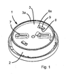
Figure 1 is an isometric view of a smoke alarm according to the present invention; -
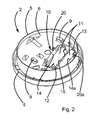
Figure 2 is an isometric view of a smoke alarm without a fastening cover and showing a protection mechanism in its position when batteries are inside, according to the present invention; -
Figure 3 is an isometric, partly cut out, view of the smoke alarm ofFigure 1 with a fastening cover, according to the present invention; -
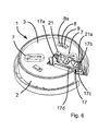
Figure 4 is a partly sectioned side view of the smoke alarm ofFigure 3 showing a protection mechanism in its position when batteries are inside, according to the present invention. -
Figure 5 is an isometric view of the smoke alarm ofFigure 1 without a fastening cover and showing a protection mechanism being in its position when batteries are removed, according to the present invention; -
Figure 6 is an isometric, partly cut out, view of the smoke alarm ofFigure 1 with a fastening cover and showing a protection mechanism being in its position when batteries are removed, according to the present invention; -
Figure 7 is a side view of a partly sectioned smoke alarm ofFigure 6 showing a protection mechanism being in its position when batteries are removed, according to the present invention. -
Figure 8 is an isometric view of the smoke alarm with a second embodiment of a protection mechanism being in its position when batteries are removed, according to the present invention; -
Figure 9 is an isometric view of the smoke alarm with a third embodiment of a protection mechanism being in its position when batteries are removed, according to the present invention. - Referring to the
Figures 1- 9 , wherein identical reference numbers denote the same members throughout the various views, asmoke alarm 1 for detecting and alarming that there is smoke in case of fire is shown. Thesmoke alarm 1 comprises ahousing 2, that is circular in the shown embodiment, and afastening cover 3 adapted to be located on the top of thehousing 2. Thehousing 2 has a bottom part 4 andannular sidewall 5 extended upwards above the bottom part 4. Thehousing 2 determines a cavity, in which all detecting smoke means are located (not shown). Thetop surface 6 of thehousing 2 is lower in relation to the peripheral top edge of theannular sidewall 5 of thehousing 2. Thefastening cover 3 has an uprightperipheral wall 3a and it is placed on thetop surface 6 with uprightperipheral wall 3a being flush with theannular sidewall 5 of thehousing 2. - Referring to
Fig. 1 ,3 and6 , thefastening cover 3 is provided withopenings 7 for fixing thefastening cover 3 to a support, e.g. a ceiling, by a screws (not shown) before thehousing 2 is attached to it. Thefastening cover 3 has also a pair ofrectangular apertures 8 withsloped snapping surfaces 8a, and thetop surface 6 of thehousing 2 is provided with twocatches 9 extending upward and each bending to opposite direction for cooperating with thesnapping surfaces 8a of theapertures 8 to connect thehousing 2 to thefastening cover 3 by pressing and rotation movement of thehousing 2 in relation to thefastening cover 3. - The
catches 9 extend from thehousing top surface 6 for such distance that they protrude throughapertures 8 in thefastening cover 3, when thehousing 2 is attached to thefastening cover 3, but being still lower than the height of the fastening coverperipheral wall 3a. Shapes of thesnapping surfaces 8a of theapertures 8 of thefastening cover 3 and thecatches 7 of thehousing 2 are such that they engage each other after rotation movement of thehousing 2 in relation to thefastening cover 3 and fasten thehousing 2 to thefastening cover 3 when the later has been fixed to the ceiling. - The
housing 2 has abattery compartment 10 for placing a set ofbatteries 11 necessary for proper function of thesmoke alarm 1. Thebattery compartment 10 is provided withclamps 12 for fastening thebatteries 11 andconnectors 13 located at the both ends of thebattery compartment 10 for connecting thebatteries 11 with detecting/alarming means for supplying electric power. - Referring to
Figures 2- 9 thebattery compartment 10 has a rectangular shape having twoopposite sidewalls bottom 15. Thebattery compartment 10, theclamps 12 and theconnectors 13 are designed to receive twocylindrical batteries 11, which are placed parallel to each other. A number ofbatteries 11 may be other than two. When thefastening cover 3 is fixed to a support, for example by a screw placed in theopenings 7 and mounted in the support, and when thebatteries 11 required for proper function of thesmoke alarm 1 are already in place in thebattery compartment 10, thehousing 2 is attached to thefastening cover 3 by pushing thehousing 2 against thefastening cover 3 in such way that thecatches 9 are received in theapertures 8 and next by performing a rotation movement of thehousing 2 in relation to the fixedfastening cover 3 which results in clamping thecatches 9 on the snapping surfaces 8a of theapertures 8. - To avoid the possibility of attaching the
housing 2 to thefastening cover 3 whenbatteries 11 have not been placed in thebattery compartment 10 and to reduce the risk of installation of anon-operational smoke alarm 1, a protection mechanism is provided in thebattery compartment 10 of thesmoke alarm 1 according to the invention. It is better seen inFig. 2 ,3 and5,6 the protection mechanism according to the invention comprises aspring member 17, which is seated in the bottom 15 of thebattery compartment 10 and movable between the two positions in relation of the bottom 15 in vertical direction. - In the embodiment of the invention shown in
Fig. 2-7 thespring member 17 is in a C-formed flat sheet-metal spring having first andsecond side arms lower arm 17c between them located laterally in thebattery compartment 10. Preferably, thelower arm 17c is bended downwards at its center to form aprotrusion 17d and the bottom 15 of thebattery compartment 10 has arecess 18, which receives theprotrusion 17d to fix the position of thespring member 17 in relation to thebattery compartment 10. As it is seen inFig. 7 , thelower arm 17c of thespring member 17 is inclined upwards from the point, in which thelower arm 17c is seated in the bottom 15 of thebattery compartment 10 to each of its outer ends, where thelower arm 17c connects with theside arms connection regions 17e. The first andsecond side arms lower arm 17c, approximately at right angle. - According to the invention, the
spring member 17 is placed extending between thebattery compartment 10 to thetop surface 6 of thehousing 2. As it is seen inFigures 2- 9 thespring member 17 may be located in an open-endedchannel comprising slots sidewalls battery compartment 10, respectively, andopenings top surface 6 of thehousing 2 and theslots openings side arms spring member 17 in them and allow theside arms lower arm 17c of thespring member 17 extends to and passes through theslots side arms openings - When there is no
battery 11 in thebattery compartment 10 thelower arm 17c of thespring member 17 is in its first position, in which at least one of theconnection regions 17e of thelower arm 17c and theside arms battery compartment 10 causing that the at least one of theside arms openings top surface 6 of thehousing 2 and prevent attachment of thehousing 2 to thefastening cover 3. (seeFigures 4 ,5 ,6 ) - Referring to
Figures 3 ,4 and6,7 thefastening cover 3 comprisesholes spring member 17 seated in thebattery compartment 10,when thehousing 2 is placed against thefastening cover 3 and thecatches 9 of thehousing 2 protrude through theapertures 8 of thefastening cover 3. Theholes openings top surface 6 of thehousing 2 when there is insufficient number ofbatteries 11 in thebattery compartment 10. The size ofholes holes housing 2 in relation to thefastening cover 3 that clamping thecatches 9 of thehousing 2 on the snapping surfaces 8a of theapertures 8 of thefastening cover 3 is prevented.. This protects the attachment of thehousing 2 to thefastening cover 3 and installation of thesmoke alarm 1 when the requiredbatteries 11 are not in the place. As it is shown inFig. 1 ,3 ,4 ,7 theholes fastening cover 3. - For proper work of the
smoke alarm 1 the predetermined number ofbatteries 11 must be put into thebattery compartment 10, fastened by theclamps 12 and pressed against theconnectors 13. - At the same time, the
batteries 11 press down thelower arm 17c of thespring member 17 towards the battery compartment bottom 15 causing that thelower arm 17c is being moved to its second position, in which theconnection region 17e of thelower arm 17c and the at least oneside arm battery compartment 10 andside arms top surface 6 of thehousing 2 to allow thehousing 2 to be attached to thefastening cover 3. Theside arms openings holes housing 2 in relation to thefastening cover 3 is no longer prevented. This allows thecatches 9 of thehousing 2 to be clamped on the snapping surfaces 8a of theapertures 8 of thefastening cover 3 and thesmoke alarm 1 to be installed to a support. (Figures 2 ,3 and4 ) - It should be noted that generally lack of at least one
battery 11 in thebattery compartment 10 does not allow thehousing 2 to be attached to thefastening cover 3, i.e. does not allow thesmoke alarm 1 to be mounted on a support. - Placing only one
battery 11 into thebattery compartment 10, when two batteries are required, will cause that still one of theside arms opening - It is obvious for a skilled person in the art that different modifications of the invention can be envisaged.
- Referring to
Fig. 8 the second embodiment of asmoke alarm 1 is shown. The smoke alarm ofFig. 8 differs from the smoke alarm described with reference toFig. 2-7 in that its protection mechanism comprises the spring member 17', which is in form of a wire spring instead of sheet-metal spring. Side arms 17'a,17'b of the spring member 17' act in the same way as theside arms spring member 17 ofFigures 2-7 . - Referring to
Fig. 9 the further embodiment of the protection mechanism ofsmoke alarm 1 is shown. The protection mechanism ofFig. 9 differs from the protection mechanism described with reference toFig. 2-7 in that it comprises anangular spring member 17". Theangular spring member 17" is placed with itsside arm 17"a at one of theside walls battery compartment 10 and soldered with itslower arm 17"c to the bottom 15 of thebattery compartment 10, instead of being seated in a recess in the bottom 15. While only onespring member 17" for one battery is shown inFig. 9 , it is understandable that also two or moresuch spring members 17" may be placed at theopposite side walls battery compartment 10 and in such case they are offset in relation to each other along thesidewalls battery compartment 10 and soldered to the bottom 15 of thebattery compartment 10 in different places. - The
lower arm 17"c of each of theangular spring members 17" may be seated in different places in the bottom 15 and side arms of each of them may be placed alternately at the opposite sidewall of thebattery compartment 10. - A battery compartment may be of different shape and/or it can house batteries of different shapes than the presented above.
-
1 smoke alarm urzadzenie alarmowe dymu 2 housing obudowa 3 fastening cover pokrywa mocujaca 3a peripheral wall ściana obwodowa 4 bottom part (of housing) dolna (obudowy)
5 annular wall(of housing) pierścieniowa ściana 6 top surface (of housing) górna powierzchnia 7 opening otwór 8 aperture wyci ecie
8a snapping surface powierzchnia zatrzaskowa 9 catch zatrzask 10 battery compartment komora baterii 11 battery bacteria 12 clamps zaczep 13 connector l cznik
14,14a sidewalls (of the battery compartment) ściana boczna 15 bottom (of the battery compartment) ściana dolna 17,17',17" spring member czton spr zysty
17a,17b 17'a,17'b 17"a,17"b side arms ramiona boczne 17c,17"c lower arm rami dolne
17d protrusion wyst p
17e connection region obszar polc zenia
18 recess wgl bienie
19, 19a slot szczelina 20,20a opening otwór przelotowy 21,21a hole okno
Claims (12)
- A smoke alarm (1) comprising:a housing (2) having a top surface (6) and delimiting a battery compartment (10) having sidewalls (14,14a) and a bottom (15), in which at least one battery (11) is placed;a fastening cover (3) adapted to be mounted to a support and to be connected with the housing (2); andprotection mechanism for preventing installation of the alarm (1) without a battery (11)characterized in thatsaid protection mechanism comprises at least one spring member (17,17',17") having at least one side arm (17a,17b;17'a,17'b;17"a,17"b) and a lower arm (17c), which is connected with the at least one side arm (17a,17b; 17'a,17'b;17"a,17"b) and located along and seated in the bottom (15) of the battery compartment (10); wherein the lower arm (17c;17"c) is movable between the first position, when at least one battery (11) is missing in the battery compartment (10), in which the connection region (17e) of the lower arm (17c; 17"c) and the at least one side arm (17a,17b;17'a,17'b;17"a,17"b) is located at distance from the bottom (15) of the battery compartment (10) and in which the at least one side arm (17a,17b;17'a,17'b;17"a,17"b) protrudes above the top surface (6) of the housing (2) and prevents attachment of the housing (2) to the fastening cover (3) and the second position, when all batteries (11) are located in the battery compartment (10), in which the connection region (17e) of the lower arm (17c; 17"c) and the at least one side arm (17a,17b;17'a,17'b;17"a,17"b) is located adjacent to the bottom (15) of the battery compartment (10) and in which the side arms (17a,17b;17'a,17'b;17"a,17"b) are retracted below the top surface (6) of the housing (2) to allow attachment of the housing (2) to the fastening cover (3).
- A smoke alarm (1) according to claim 1, characterized in that the side arm (17a,17b;17'a,17'b;17"a,17"b) is placed extending between the battery compartment (10) and the top surface (6) of the housing (2), in which the side arm (17a,17b;17'a,17'b;17"a,17"b) of the spring member (17,17',17") can freely moved between the protruding and retracted positions.
- A smoke alarm (1) according to claim 2, characterized in that the side arm (17a,17b;17'a,17'b;17"a,17"b) is placed in an open-ended path, which comprises slots (19,19a) formed between sidewalls (14,14a) and the bottom (15) of the battery compartment (10), respectively, and openings (20, 20a) extending between the slots (19,19a) and the top surface (6) of the housing (2), respectively.
- A smoke alarm (1) according to any of claims 1-3 characterized in that the lower arm (17c;17"c) of the spring member (17,17',17") is inclined upwards from the point, in which the lower arm (17c;17"c) is seated in the bottom (15) of the battery compartment (10) to its outer end, where the lower arm (17c; 17"c) connects with the at least one side arm (17a,17b;17'a,17'b;17"a,17"b).
- A smoke alarm (1) according to any of claims 1-4 characterized in that the side arm (17a, 17b; 17'a,17'b; 17"a,17"b) is bended upwards from the lower arm (17c; 17"c) approximately at right angle.
- A smoke alarm (1) according to any of claims 1-5 characterized in that the spring member (17,17') is C-shaped and its lower arm (17c) extends laterally in the battery compartment (10) being bending downwards at its center to form a protrusion (17d) and the bottom (15) of the battery compartment (10) has a recess (18), which receives the protrusion (17d) to seat the spring member (17,17') in the battery compartment (10).
- A smoke alarm (1) according to any of claims 1-5 characterized in that the spring member (17") is angular and it is placed with its side arm (17"a) at one of the side walls (14a,14b) of the battery compartment (10) and soldered with its lower arm (17"c) to the bottom (15) of the battery compartment (10).
- A smoke alarm (1) according to claim 7 characterized in that at least two angular spring members (17") are placed in the battery compartment (10) being offset in relation to each other along the sidewalls (14,14a) the lower arm (17"c) of each of them being soldered to the bottom (15) in different points.
- A smoke alarm (1) according to claims 6-8, characterized in that the spring member (17,17',17") is a sheet-metal spring or a wire spring.
- A smoke alarm (1) according to any of claims 1-7 characterized in that the top surface (6) of the housing (2) is provided with two catches (9) extending upward and bending to opposite directions and the fastening cover (3) is provided with apertures (8) for receiving the catches (9) and clamping them to the fasten cover (3) by rotation movement of the housing (2) in relation to the fastening cover (3).
- A smoke alarm (1) according to any of claims 1-8 characterized in that the fastening cover (3) comprises holes (21, 21a), which are aligned with the openings (20,20a) when the housing (2) is placed against the fastening cover (3) and the catches (9) of the housing (2) protrude through the apertures (8) of the fastening cover (3); wherein the holes (21,21a) house portions of the side arms (17a,17b) protruding through the openings (20,20a) to prevent rotation movement of the housing (2) in relation to the fastening cover (3).
- A smoke alarm (1) according to claims 8-9 characterized in that the catches (9) and the projections (21,21 a) are lower than the upright peripheral wall (3a) of the fastening cover (3).
Applications Claiming Priority (1)
| Application Number | Priority Date | Filing Date | Title |
|---|---|---|---|
| PL392067A PL392067A1 (en) | 2010-08-05 | 2010-08-05 | Smoke alarm with safety mechanism |
Publications (2)
| Publication Number | Publication Date |
|---|---|
| EP2416299A2 true EP2416299A2 (en) | 2012-02-08 |
| EP2416299A3 EP2416299A3 (en) | 2012-10-03 |
Family
ID=45044816
Family Applications (1)
| Application Number | Title | Priority Date | Filing Date |
|---|---|---|---|
| EP11006385A Withdrawn EP2416299A3 (en) | 2010-08-05 | 2011-08-03 | A smoke alarm with protection mechanism |
Country Status (2)
| Country | Link |
|---|---|
| EP (1) | EP2416299A3 (en) |
| PL (1) | PL392067A1 (en) |
Cited By (4)
| Publication number | Priority date | Publication date | Assignee | Title |
|---|---|---|---|---|
| CN108673028A (en) * | 2018-07-27 | 2018-10-19 | 昆山特朗普新能源汽车零部件有限公司 | A kind of welding fixture |
| CN109713186A (en) * | 2019-01-08 | 2019-05-03 | 广州博冠智能科技有限公司 | A kind of compartment cover of intelligent remote controller battery cover |
| CN111463379A (en) * | 2020-04-09 | 2020-07-28 | 深圳麦乐克传感技术有限公司 | Smoke alarm for preventing battery from being neglected to be installed |
| CN111463380A (en) * | 2020-04-09 | 2020-07-28 | 深圳麦乐克传感技术有限公司 | Battery leak-proof structure and smoke alarm |
Family Cites Families (7)
| Publication number | Priority date | Publication date | Assignee | Title |
|---|---|---|---|---|
| US4870395A (en) * | 1988-03-10 | 1989-09-26 | Seatt Corporation | Battery powered smoke alarm safety lockout system |
| US5103216A (en) * | 1989-06-12 | 1992-04-07 | Pittway Corporation | Improperly inserted battery detector |
| US5966079A (en) * | 1997-02-19 | 1999-10-12 | Ranco Inc. Of Delaware | Visual indicator for identifying which of a plurality of dangerous condition warning devices has issued an audible low battery warning signal |
| AU2002953417A0 (en) * | 2002-12-18 | 2003-01-09 | Gerard Industries Pty Ltd | Detector assembly suited to smoke alarms |
| US7504960B2 (en) * | 2005-11-10 | 2009-03-17 | Patrick McGrath | Remotely located battery for a smoke detector |
| JP4676524B2 (en) * | 2008-10-22 | 2011-04-27 | 能美防災株式会社 | Fire alarm |
| DE102010027944A1 (en) * | 2010-04-20 | 2011-10-20 | Robert Bosch Gmbh | Housing for fire alarm i.e. smoke warning alarm unit, utilized in e.g. ceiling of public building, for detecting fire in private living area, has check unit converted as actuator portion from locking position into releasing position |
-
2010
- 2010-08-05 PL PL392067A patent/PL392067A1/en not_active Application Discontinuation
-
2011
- 2011-08-03 EP EP11006385A patent/EP2416299A3/en not_active Withdrawn
Non-Patent Citations (1)
| Title |
|---|
| None |
Cited By (5)
| Publication number | Priority date | Publication date | Assignee | Title |
|---|---|---|---|---|
| CN108673028A (en) * | 2018-07-27 | 2018-10-19 | 昆山特朗普新能源汽车零部件有限公司 | A kind of welding fixture |
| CN108673028B (en) * | 2018-07-27 | 2023-12-22 | 昆山特朗普新能源汽车零部件有限公司 | Welding fixture |
| CN109713186A (en) * | 2019-01-08 | 2019-05-03 | 广州博冠智能科技有限公司 | A kind of compartment cover of intelligent remote controller battery cover |
| CN111463379A (en) * | 2020-04-09 | 2020-07-28 | 深圳麦乐克传感技术有限公司 | Smoke alarm for preventing battery from being neglected to be installed |
| CN111463380A (en) * | 2020-04-09 | 2020-07-28 | 深圳麦乐克传感技术有限公司 | Battery leak-proof structure and smoke alarm |
Also Published As
| Publication number | Publication date |
|---|---|
| EP2416299A3 (en) | 2012-10-03 |
| PL392067A1 (en) | 2012-02-13 |
Similar Documents
| Publication | Publication Date | Title |
|---|---|---|
| JPH081572Y2 (en) | Printed circuit board connector | |
| US7686622B2 (en) | Plug connector with mating protection | |
| US10164327B2 (en) | Antenna device | |
| US7252549B2 (en) | Connector, receptacle for connector and plug for connector | |
| US7140890B1 (en) | Electrical connector assembly capable of being moved by vacuum-suction device | |
| EP2416299A2 (en) | A smoke alarm with protection mechanism | |
| US20160322720A1 (en) | Connector | |
| EP2432091B1 (en) | Bracket structure of electrical connection box | |
| EP3149809B1 (en) | Electrical connector for use with printed circuit boards | |
| US7001212B1 (en) | Surface mountable retention bracket for electrical connector | |
| EP3205808B1 (en) | Screening arrangement with mounting brackets | |
| US6554655B2 (en) | Modular lug block assembly | |
| US7182641B2 (en) | Electrical connector with shield case | |
| US7312761B2 (en) | Antenna device mounted on vehicle | |
| ES2922234T3 (en) | Connector Arrangement | |
| CN220368159U (en) | Electronic connection assembly | |
| JP2002507844A (en) | Mounting casing fixed to the wall | |
| JP3393993B2 (en) | Electrical connector | |
| US7641497B2 (en) | Socket with bolt | |
| US20070267284A1 (en) | Micro switch | |
| US7040913B2 (en) | Controller module positioning and alignment frame | |
| CN215909393U (en) | Panel assembly and air conditioner | |
| CN216120930U (en) | Embeddable multi-type USB power socket module | |
| CN215682837U (en) | Terminal fixing assembly and frequency converter | |
| CN108286698B (en) | Multipurpose combined connecting piece |
Legal Events
| Date | Code | Title | Description |
|---|---|---|---|
| AK | Designated contracting states |
Kind code of ref document: A2 Designated state(s): AL AT BE BG CH CY CZ DE DK EE ES FI FR GB GR HR HU IE IS IT LI LT LU LV MC MK MT NL NO PL PT RO RS SE SI SK SM TR |
|
| AX | Request for extension of the european patent |
Extension state: BA ME |
|
| PUAI | Public reference made under article 153(3) epc to a published international application that has entered the european phase |
Free format text: ORIGINAL CODE: 0009012 |
|
| PUAL | Search report despatched |
Free format text: ORIGINAL CODE: 0009013 |
|
| AK | Designated contracting states |
Kind code of ref document: A3 Designated state(s): AL AT BE BG CH CY CZ DE DK EE ES FI FR GB GR HR HU IE IS IT LI LT LU LV MC MK MT NL NO PL PT RO RS SE SI SK SM TR |
|
| AX | Request for extension of the european patent |
Extension state: BA ME |
|
| RIC1 | Information provided on ipc code assigned before grant |
Ipc: H01M 2/10 20060101ALI20120827BHEP Ipc: G08B 17/10 20060101AFI20120827BHEP Ipc: G08B 29/18 20060101ALI20120827BHEP |
|
| STAA | Information on the status of an ep patent application or granted ep patent |
Free format text: STATUS: THE APPLICATION IS DEEMED TO BE WITHDRAWN |
|
| 18D | Application deemed to be withdrawn |
Effective date: 20130404 |