EP2415974A2 - Sealed rotator shaft for borescopic inspection - Google Patents
Sealed rotator shaft for borescopic inspection Download PDFInfo
- Publication number
- EP2415974A2 EP2415974A2 EP11176282A EP11176282A EP2415974A2 EP 2415974 A2 EP2415974 A2 EP 2415974A2 EP 11176282 A EP11176282 A EP 11176282A EP 11176282 A EP11176282 A EP 11176282A EP 2415974 A2 EP2415974 A2 EP 2415974A2
- Authority
- EP
- European Patent Office
- Prior art keywords
- drive
- drive connection
- shaft
- rotator
- biased
- Prior art date
- Legal status (The legal status is an assumption and is not a legal conclusion. Google has not performed a legal analysis and makes no representation as to the accuracy of the status listed.)
- Granted
Links
Images


Classifications
-
- F—MECHANICAL ENGINEERING; LIGHTING; HEATING; WEAPONS; BLASTING
- F01—MACHINES OR ENGINES IN GENERAL; ENGINE PLANTS IN GENERAL; STEAM ENGINES
- F01D—NON-POSITIVE DISPLACEMENT MACHINES OR ENGINES, e.g. STEAM TURBINES
- F01D21/00—Shutting-down of machines or engines, e.g. in emergency; Regulating, controlling, or safety means not otherwise provided for
- F01D21/003—Arrangements for testing or measuring
-
- F—MECHANICAL ENGINEERING; LIGHTING; HEATING; WEAPONS; BLASTING
- F01—MACHINES OR ENGINES IN GENERAL; ENGINE PLANTS IN GENERAL; STEAM ENGINES
- F01D—NON-POSITIVE DISPLACEMENT MACHINES OR ENGINES, e.g. STEAM TURBINES
- F01D25/00—Component parts, details, or accessories, not provided for in, or of interest apart from, other groups
- F01D25/34—Turning or inching gear
-
- F—MECHANICAL ENGINEERING; LIGHTING; HEATING; WEAPONS; BLASTING
- F02—COMBUSTION ENGINES; HOT-GAS OR COMBUSTION-PRODUCT ENGINE PLANTS
- F02C—GAS-TURBINE PLANTS; AIR INTAKES FOR JET-PROPULSION PLANTS; CONTROLLING FUEL SUPPLY IN AIR-BREATHING JET-PROPULSION PLANTS
- F02C7/00—Features, components parts, details or accessories, not provided for in, or of interest apart form groups F02C1/00 - F02C6/00; Air intakes for jet-propulsion plants
- F02C7/32—Arrangement, mounting, or driving, of auxiliaries
-
- Y—GENERAL TAGGING OF NEW TECHNOLOGICAL DEVELOPMENTS; GENERAL TAGGING OF CROSS-SECTIONAL TECHNOLOGIES SPANNING OVER SEVERAL SECTIONS OF THE IPC; TECHNICAL SUBJECTS COVERED BY FORMER USPC CROSS-REFERENCE ART COLLECTIONS [XRACs] AND DIGESTS
- Y10—TECHNICAL SUBJECTS COVERED BY FORMER USPC
- Y10T—TECHNICAL SUBJECTS COVERED BY FORMER US CLASSIFICATION
- Y10T403/00—Joints and connections
- Y10T403/10—Selectively engageable hub to shaft connection
-
- Y—GENERAL TAGGING OF NEW TECHNOLOGICAL DEVELOPMENTS; GENERAL TAGGING OF CROSS-SECTIONAL TECHNOLOGIES SPANNING OVER SEVERAL SECTIONS OF THE IPC; TECHNICAL SUBJECTS COVERED BY FORMER USPC CROSS-REFERENCE ART COLLECTIONS [XRACs] AND DIGESTS
- Y10—TECHNICAL SUBJECTS COVERED BY FORMER USPC
- Y10T—TECHNICAL SUBJECTS COVERED BY FORMER US CLASSIFICATION
- Y10T74/00—Machine element or mechanism
- Y10T74/19—Gearing
- Y10T74/19023—Plural power paths to and/or from gearing
- Y10T74/19074—Single drive plural driven
- Y10T74/19079—Parallel
Definitions
- This application relates to a sealed rotator shaft for use in borescopic inspection.
- Gas turbine engines typically include a compressor section compressing air and delivering the compressed air into a combustion section.
- the compressed air is mixed with fuel and combusted, and products of this combustion pass downstream over turbine rotors.
- the turbine rotors are driven to rotate, and in turn rotate rotors in the compressor section.
- borescopic inspection One method of inspecting a gas turbine engine is called borescopic inspection. With borescopic inspection, probes are inserted through holes in the sections in a gas turbine engine. For certain aspects of the inspection, the turbine and compressor rotors must be rotated. Thus, it is known to have a rotator shaft associated with a gas turbine engine.
- the rotator shaft has typically been part of an accessory drive gearbox.
- a sealed cover is aligned with an accessory shaft.
- the accessory shaft is connected through a gear train back to a main engine shaft connecting the turbine rotors and the compressor rotors.
- borescopic inspection is to occur, the cover is removed, and a technician will insert a tool that engages the accessory shaft to rotate the turbine rotors.
- inspectors have sometimes neglected to replace the cover after the inspection is complete. This is undesirable, as the oil may drain out of an accessory gear case once the engine is returned to operation.
- a rotator drive connection for a gas turbine engine accessory box has a shaft connected to and driven by a main shaft in a gas turbine engine through a gear train.
- a first drive connection allows selective drive of the shaft.
- a biased drive member includes a second drive connection selectively brought into contact with the first drive connection to allow rotation of the main shaft. The biased drive member biases the second drive connection out of contact with the first drive connection.
- Figure 1 shows a gas turbine engine 20 incorporating borescopic probes 22.
- the probes 22 extend through inspection openings in a housing or casing for the engine 20.
- the probes are shown schematically in this Figure.
- a compressor rotor section 24 is connected to a turbine rotor section 26 by a shaft 28.
- the turbine rotors 26 are driven to rotate, and rotate the compressor rotors 24 through the shaft 28.
- a gear interface 32 drives an accessory drive gear train shaft 30.
- the gear train shaft 30 is connected through another gear interface 34 to drive a shaft 36.
- Shaft 36 drives a plurality of accessory drive shafts 38.
- Each of the accessory drive shafts 38 is connected to drive an accessory 40.
- One of the accessory drive shafts 38 which is operable to drive an accessory 42, is provided with a borescopic rotator drive connection 46.
- a cover 44 selectively encloses an accessory gear box 51, such that oil can be maintained within the gear box 51 during operation of the engine. However, cover 44 must be removed for rotator tool 48 to be brought into the gear connection 46 during borescopic inspection. Tool 48 is then utilized to slowly rotate the drive shaft 28, and hence the rotors 26 and 24. As mentioned above, with this embodiment, it has sometimes been the case that the cover 44 was not returned after completion of inspection.
- Figure 2 shows an embodiment 19 according to aspects of the invention.
- the engine is almost identical to Figure 1 .
- the drive connection 46 on the accessory shaft 38 is provided with a unique rotator drive 90.
- a biased drive member 54 and first drive connection 52 form rotator drive 90.
- the biased drive member 54 is biased to a position removed from the first drive connection 52, and is sealed within the housing 51.
- the rotator tool 48 can be brought into contact with the biased drive member 54 which is then forced against a bias force into engagement with the first drive connection 52. At that time, rotation of the drive shaft 28 and rotors 24 and 26 can occur.
- Figure 3 shows another embodiment 220, which is similar to the Figure 2 embodiment, other than the fact that the rotator drive 90 has a biased drive member 62 and first drive connection 66 associated with a lower housing 151. Utilizing this location allows removal of the biased drive member 62, for disassembly of the gear train shaft 30.
- the gear train shaft 30 is an "accessory shaft” in that it is part of the gear drive for driving the accessories. For purposes of the claims in this application, the shaft 30 is thus "an accessory shaft.”
- FIG. 4 shows the biased drive member 54 having a main shaft 55.
- Main shaft 55 is movable within a housing 70.
- a second drive connection 74 in the form of gear teeth at an inner end selectively engage with the first drive connection 52.
- Seals 72 are received in grooves in an outer periphery of the housing 70. Intermediate lube passages 73 and 59 can supply lubrication to the shaft 55. A plug surface 76 can selectively receive a drive portion of the rotator tool 48. A clip 78 provides a stop for a spring washer 80, which biases the shaft 55 outwardly of the housing 70. The second drive connection 74 may hit an inner surface of the housing 70 to provide a stop surface. Thus, when the borescopic inspection is not ongoing, the shaft 55 is in a position like that shown in Figure 4 , and the seals 72 prevent leakage of lubricant.
- Figure 5 shows the engagement of the rotator tool 48.
- the rotator tool 48 is brought into engagement and the shaft 55 is forced inwardly against the force of the spring 80.
- the second drive connection 74 is brought into engagement with a first drive connection 52 on the accessory shaft 38.
- the teeth may be provided with a bow front cross-section.
- FIG. 6 shows other features which can optionally be incorporated into any one of the embodiments in this application.
- a dust guard 85 can be positioned over the shaft 55 when borescopic operation is not ongoing.
- the dust guard 85 is optional, and the removal of the dust guard 85 will not result in any oil leaking outwardly of the interior of the gear box 51, or lower housing 151. Rather, the main purpose of dust guard 85 is to keep the area of the spring 80, and the outer face of the shaft 55 relatively clean.
- Threads 87 can be provided for use of a pull or retractor tool 89. Should the second drive connection 74 lock into the first drive connection 52, it may sometimes be helpful to thread the retractor tool 89 onto the threads 87, and then pull the shaft 55 outwardly.
- FIG 7 shows another embodiment 191.
- a plurality of bolt holes 100 are provided in the housing 70. This provides a mounting surface for the use of an automated rotator 94, shown schematically.
- the bolt holes 100 provide mounting holes to receive bolts 98 securing a rotator housing 96 to housing 70.
- Automated rotator 94 has a drive 92 that extends inwardly into the plug surface 76.
- Automated rotator tools are known, and have been utilized with arrangements such as shown in Figure 1 . However, the embodiments of this application would also extend to the use of such an automated tool.
- FIG. 8A shows another embodiment 190.
- Embodiment 190 is particularly useful when housing space is at a premium.
- Embodiment 190 has the shaft 114, lube passages 111 and 113, and seals 72.
- the gear teeth 112 function as the second drive connection.
- the housing 118 has a bore 116, and there is a spring connection 122 as in the earlier embodiment.
- the 8A position is the engaged position. However, due to the size of forward boss 120 on the housing 118, even in the retracted position, the shaft 114 does not extend outwardly of the housing 118.
- Figure 8B This is generally shown in Figure 8B , which does show another embodiment 130.
- the embodiment 130 is similar to the Figure 8A embodiment, but does not include the lube passages.
- second drive connections or gear teeth, which essentially are spline drive connections with the first drive connection on the accessory shaft.
- the spline drive connections have the same number of teeth as the first drive connection.
- Figure 9 shows yet another embodiment 131, wherein the spline drive of the earlier embodiments is replaced by an internal gear drive 134.
- the internal gear drive 134 has fewer teeth than the first drive connection 136.
- the centerline of the drive shaft connected to the drive gear 134 has been offset relative to the shaft 38 to bring the smaller drive gear into engagement.
- the housing 132 mounts the biased drive member for selectively moving the gear 134 into engagement.
- Figure 10 shows an embodiment 140, where an external gear drive 144 is provided with housing 142. Again, there are fewer gear teeth on the external gear drive 144, and they are engaged with gear teeth 146 on the outer surface of an accessory drive shaft 38.
Abstract
Description
- This application relates to a sealed rotator shaft for use in borescopic inspection.
- Gas turbine engines are known, and typically include a compressor section compressing air and delivering the compressed air into a combustion section. The compressed air is mixed with fuel and combusted, and products of this combustion pass downstream over turbine rotors. The turbine rotors are driven to rotate, and in turn rotate rotors in the compressor section.
- One method of inspecting a gas turbine engine is called borescopic inspection. With borescopic inspection, probes are inserted through holes in the sections in a gas turbine engine. For certain aspects of the inspection, the turbine and compressor rotors must be rotated. Thus, it is known to have a rotator shaft associated with a gas turbine engine.
- In the existing art, the rotator shaft has typically been part of an accessory drive gearbox. A sealed cover is aligned with an accessory shaft. The accessory shaft is connected through a gear train back to a main engine shaft connecting the turbine rotors and the compressor rotors. When borescopic inspection is to occur, the cover is removed, and a technician will insert a tool that engages the accessory shaft to rotate the turbine rotors. In the past, inspectors have sometimes neglected to replace the cover after the inspection is complete. This is undesirable, as the oil may drain out of an accessory gear case once the engine is returned to operation.
- A rotator drive connection for a gas turbine engine accessory box has a shaft connected to and driven by a main shaft in a gas turbine engine through a gear train. A first drive connection allows selective drive of the shaft. A biased drive member includes a second drive connection selectively brought into contact with the first drive connection to allow rotation of the main shaft. The biased drive member biases the second drive connection out of contact with the first drive connection. A gas turbine engine accessory box and a method of borescopic inspection are also disclosed and claimed.
- These and other features of the present invention can be best understood from the following specification and drawings, the following of which is a brief description.
-
-
Figure 1 schematically shows a prior art engine. -
Figure 2 shows a first inventive schematic. -
Figure 3 shows a second embodiment inventive schematic. -
Figure 4 shows a first embodiment rotator shaft. -
Figure 5 shows the first embodiment rotator shaft engaged to drive the engine shaft. -
Figure 6 shows some optional features. -
Figure 7 shows other optional features. -
Figure 8A shows a second embodiment in a first position. -
Figure 8B shows yet another embodiment. -
Figure 9 shows yet another embodiment. -
Figure 10 shows yet another embodiment. -
Figure 1 shows agas turbine engine 20 incorporatingborescopic probes 22. As known, theprobes 22 extend through inspection openings in a housing or casing for theengine 20. The probes are shown schematically in this Figure. Acompressor rotor section 24 is connected to aturbine rotor section 26 by ashaft 28. During operation of thegas turbine engine 20, theturbine rotors 26 are driven to rotate, and rotate thecompressor rotors 24 through theshaft 28. - As shown, a
gear interface 32 drives an accessory drivegear train shaft 30. Thegear train shaft 30 is connected through anothergear interface 34 to drive ashaft 36. Shaft 36 drives a plurality ofaccessory drive shafts 38. Each of theaccessory drive shafts 38 is connected to drive anaccessory 40. One of theaccessory drive shafts 38, which is operable to drive anaccessory 42, is provided with a borescopicrotator drive connection 46. Acover 44 selectively encloses anaccessory gear box 51, such that oil can be maintained within thegear box 51 during operation of the engine. However,cover 44 must be removed forrotator tool 48 to be brought into thegear connection 46 during borescopic inspection.Tool 48 is then utilized to slowly rotate thedrive shaft 28, and hence therotors cover 44 was not returned after completion of inspection. -
Figure 2 shows anembodiment 19 according to aspects of the invention. Inembodiment 19, the engine is almost identical toFigure 1 . However, thedrive connection 46 on theaccessory shaft 38 is provided with aunique rotator drive 90. Together, abiased drive member 54 andfirst drive connection 52form rotator drive 90. As will be explained below, thebiased drive member 54 is biased to a position removed from thefirst drive connection 52, and is sealed within thehousing 51. - The
rotator tool 48 can be brought into contact with thebiased drive member 54 which is then forced against a bias force into engagement with thefirst drive connection 52. At that time, rotation of thedrive shaft 28 androtors -
Figure 3 shows anotherembodiment 220, which is similar to theFigure 2 embodiment, other than the fact that therotator drive 90 has abiased drive member 62 andfirst drive connection 66 associated with alower housing 151. Utilizing this location allows removal of thebiased drive member 62, for disassembly of thegear train shaft 30. Thegear train shaft 30 is an "accessory shaft" in that it is part of the gear drive for driving the accessories. For purposes of the claims in this application, theshaft 30 is thus "an accessory shaft." - There will be several embodiments disclosed below for the
biased drive members Figure 2 orFigure 3 application, as well as any number of other locations. For example, althoughFigures 5 ,9, and 10 depictaccessory shaft 38 andfirst drive connection 52, these elements can be substituted bygear train shaft 30 andfirst drive connection 66 in accordance withembodiment 220 ofFigure 3 .
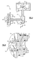
Figure 4 shows thebiased drive member 54 having amain shaft 55.Main shaft 55 is movable within ahousing 70. Asecond drive connection 74 in the form of gear teeth at an inner end selectively engage with thefirst drive connection 52. -
Seals 72 are received in grooves in an outer periphery of thehousing 70.Intermediate lube passages shaft 55. Aplug surface 76 can selectively receive a drive portion of therotator tool 48. Aclip 78 provides a stop for aspring washer 80, which biases theshaft 55 outwardly of thehousing 70. Thesecond drive connection 74 may hit an inner surface of thehousing 70 to provide a stop surface. Thus, when the borescopic inspection is not ongoing, theshaft 55 is in a position like that shown inFigure 4 , and theseals 72 prevent leakage of lubricant. -
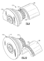
Figure 5 shows the engagement of therotator tool 48. Therotator tool 48 is brought into engagement and theshaft 55 is forced inwardly against the force of thespring 80. In this manner, thesecond drive connection 74 is brought into engagement with afirst drive connection 52 on theaccessory shaft 38. To facilitate this connection, the teeth may be provided with a bow front cross-section. -
Figure 6 shows other features which can optionally be incorporated into any one of the embodiments in this application. First, adust guard 85 can be positioned over theshaft 55 when borescopic operation is not ongoing. Thedust guard 85 is optional, and the removal of thedust guard 85 will not result in any oil leaking outwardly of the interior of thegear box 51, orlower housing 151. Rather, the main purpose ofdust guard 85 is to keep the area of thespring 80, and the outer face of theshaft 55 relatively clean. - A second feature is shown forward of the
plug surface 76.Threads 87 can be provided for use of a pull orretractor tool 89. Should thesecond drive connection 74 lock into thefirst drive connection 52, it may sometimes be helpful to thread theretractor tool 89 onto thethreads 87, and then pull theshaft 55 outwardly. -
Figure 7 shows anotherembodiment 191. Inembodiment 191, a plurality of bolt holes 100 are provided in thehousing 70. This provides a mounting surface for the use of anautomated rotator 94, shown schematically. The bolt holes 100 provide mounting holes to receivebolts 98 securing arotator housing 96 tohousing 70. Automatedrotator 94 has a drive 92 that extends inwardly into theplug surface 76. Automated rotator tools are known, and have been utilized with arrangements such as shown inFigure 1 . However, the embodiments of this application would also extend to the use of such an automated tool. -
Figure 8A shows anotherembodiment 190.Embodiment 190 is particularly useful when housing space is at a premium.Embodiment 190 has theshaft 114,lube passages gear teeth 112 function as the second drive connection. Thehousing 118 has abore 116, and there is aspring connection 122 as in the earlier embodiment. The 8A position is the engaged position. However, due to the size offorward boss 120 on thehousing 118, even in the retracted position, theshaft 114 does not extend outwardly of thehousing 118. - This is generally shown in
Figure 8B , which does show anotherembodiment 130. Theembodiment 130 is similar to theFigure 8A embodiment, but does not include the lube passages. - The embodiments to this point have included second drive connections, or gear teeth, which essentially are spline drive connections with the first drive connection on the accessory shaft. The spline drive connections have the same number of teeth as the first drive connection.
-
Figure 9 shows yet anotherembodiment 131, wherein the spline drive of the earlier embodiments is replaced by aninternal gear drive 134. Theinternal gear drive 134 has fewer teeth than thefirst drive connection 136. The centerline of the drive shaft connected to thedrive gear 134 has been offset relative to theshaft 38 to bring the smaller drive gear into engagement. Again, thehousing 132 mounts the biased drive member for selectively moving thegear 134 into engagement. -
Figure 10 shows anembodiment 140, where anexternal gear drive 144 is provided withhousing 142. Again, there are fewer gear teeth on theexternal gear drive 144, and they are engaged withgear teeth 146 on the outer surface of anaccessory drive shaft 38. - Although embodiments of this invention have been disclosed, a worker of ordinary skill in this art would recognize that certain modifications would come within the scope of this invention. For that reason, the following claims should be studied to determine the true scope and content of this invention.
Claims (15)
- A rotator drive connection (90) for a gas turbine engine accessory box comprising:an accessory shaft (30;38) to be connected to be driven by a main shaft (28) in a gas turbine engine through a gear train (32,34);a first drive connection (52;66) for driving said accessory shaft; anda biased drive member (54;62) including a second drive connection (74;134;144) to be selectively brought into contact with said first drive connection (52;66) to allow rotation of the main shaft (28), said biased drive member (54;62) biasing said second drive connection (74;134;144) out of contact with said first drive connection (52;66).
- The rotator drive connection (90) as set forth in claim 1, wherein said second drive connection (74;134;144) includes gear teeth (112) that are selectively brought into engagement with gear teeth (136;146) on said first drive connection (52;66).
- The rotator drive connection (90) as set forth in claim 2, wherein said gear teeth (112) on said second drive connection (74) include a spline drive having the same number of teeth as are on an internal surface of said first drive connection (52;66).
- The rotator drive connection (90) as set forth in claim 2, wherein said second drive connection (74) has fewer teeth than the gear teeth (136) in said first drive connection (52;66), and said second drive connection is an internal drive gear (134) movable into a bore of said first drive connection (52;66), or wherein said second drive connection (74) has fewer teeth than the gear teeth (146) in said first drive connection (52;66), and said second drive connection is positioned to be an external drive gear (144) outwardly of said first drive connection (52;66).
- The rotator drive connection (90) as set forth in any preceding claim, said biased drive member (54;62) having a drive shaft (55;114) that includes a bias member (80;122) at an outer end, said bias member biasing said shaft and said second drive connection (74;134;144) outwardly and away from said first drive connection (52;66), preferably wherein said bias member includes a spring washer (80;122).
- The rotator drive connection (90) as set forth in any preceding claim, wherein a dust cover (85) is positioned outwardly of said biased drive member (54;62).
- The rotator drive connection (90) as set forth in any preceding claim, wherein a biased shaft (55;114) carrying said second drive connection (74;134;144) is provided with threads to allow the attachment of a retractor tool (89) if said biased shaft becomes stuck in said first drive connection (52;66).
- The rotator drive connection (90) as set forth in any of claims 1 to 6, wherein a housing (51;70;118;132;142;151) for said biased drive member (54;62) includes a plurality of mounting holes (100) such that an automated rotator (94) can be mounted to said housing, with said automated rotator driving said first drive connection (52;66) by biasing said second drive connection (74;134;144) into contact, and then rotating said second drive connection.
- The rotator drive connection (90) as set forth in any of claims 1 to 6, wherein said biased drive member (54;62) includes a movable shaft (55;114) which carries said second drive connection (74;134;144) and which is sealed within a housing (51;70;118;132;142;151) for the rotator drive connection when said biased drive member has biased said shaft and said second drive connection out of contact with said first drive connection (52;66).
- The rotator drive connection (90) as set forth in any of claims 1 to 6, wherein a plug drive surface (76) is provided for receiving a rotator drive (48;94) to drive said biased drive member (54;62) to rotate said second drive connection (74;134;144), and hence said first drive connection (52;66).
- A gas turbine engine accessory box comprising:a rotator drive connection (90) as claimed in any preceding claim,
wherein said accessory drive shaft (30;38) is configured to drive a plurality of accessory shafts, with at least one of said accessory shafts being provided with said rotator drive connection which is a borescopic rotator connection, wherein said first drive connection is for driving said at least one accessory shaft. - The gas turbine engine accessory box as set forth in claim 11, wherein an accessory gear train (32,34) is driven by the main drive shaft (28) of the gas turbine engine, and extends away from the main drive to in turn drive said accessory drive shaft (30;38), and a housing receives said biased drive member (54;62) such that said biased drive member can be removed from said housing to allow removal of said accessory gear train (32,34).
- A method of borescopic inspection of a gas turbine engine comprising the steps of:(a) inserting probes (22) through openings in a gas turbine engine housing;(b) moving a biased drive member (54;62), which is biased out of engagement with a shaft (36) associated with a main drive shaft (28) for the gas turbine engine, into engagement; and(c) rotating said biased drive member such that an accessory drive shaft (30;38) is rotated to in turn rotate said main drive shaft, while said borescopic probes (20) inspect components within said gas turbine engine housing.
- The method as set forth in claim 13, wherein a biased shaft (55;114) carrying a second drive connection (74;134;144) is provided with an internal surface with threads to allow the attachment of a retractor tool (89) if said biased shaft becomes stuck in a first drive connection.
- The method as set forth in claim 13, wherein a housing for said shaft includes a plurality of mounting holes (100) such that an automated rotator (94) can be mounted to said housing, with said automated rotator driving said first drive connection (52;66) by biasing said second drive connection (74;134;144) into contact, and then rotating said second drive connection.
Applications Claiming Priority (1)
| Application Number | Priority Date | Filing Date | Title |
|---|---|---|---|
| US12/848,243 US8438949B2 (en) | 2010-08-02 | 2010-08-02 | Sealed rotator shaft for borescopic inspection |
Publications (3)
| Publication Number | Publication Date |
|---|---|
| EP2415974A2 true EP2415974A2 (en) | 2012-02-08 |
| EP2415974A3 EP2415974A3 (en) | 2012-06-06 |
| EP2415974B1 EP2415974B1 (en) | 2015-12-16 |
Family
ID=44653992
Family Applications (1)
| Application Number | Title | Priority Date | Filing Date |
|---|---|---|---|
| EP11176282.9A Not-in-force EP2415974B1 (en) | 2010-08-02 | 2011-08-02 | Sealed rotator shaft for borescopic inspection |
Country Status (2)
| Country | Link |
|---|---|
| US (1) | US8438949B2 (en) |
| EP (1) | EP2415974B1 (en) |
Cited By (1)
| Publication number | Priority date | Publication date | Assignee | Title |
|---|---|---|---|---|
| EP4015803A1 (en) * | 2020-12-17 | 2022-06-22 | Hamilton Sundstrand Corporation | Quick access engine rotator pad |
Families Citing this family (3)
| Publication number | Priority date | Publication date | Assignee | Title |
|---|---|---|---|---|
| FR2952121B1 (en) * | 2009-10-29 | 2011-12-23 | Snecma | DEVICE FOR THE MECHANICAL DRIVE OF THE HIGH PRESSURE BODY OF AN AIRCRAFT ENGINE |
| US20160363055A1 (en) * | 2015-06-09 | 2016-12-15 | Rolls-Royce North American Technologies, Inc. | Off-set geared turbofan engine |
| CN105736077B (en) * | 2015-06-30 | 2018-11-13 | 国网新疆电力公司阿克苏供电公司 | A kind of steam turbine Special hand turning tool |
Family Cites Families (15)
| Publication number | Priority date | Publication date | Assignee | Title |
|---|---|---|---|---|
| US3992991A (en) * | 1975-06-19 | 1976-11-23 | Addressograph Multigraph Corporation | Non-rotating handwheel |
| US4078864A (en) | 1976-07-08 | 1978-03-14 | United Technologies Corporation | Method and apparatus for viewing and measuring damage in an inaccessible area |
| US5653581A (en) | 1994-11-29 | 1997-08-05 | United Technologies Corporation | Case-tied joint for compressor stators |
| FR2736092B1 (en) * | 1995-06-28 | 1997-08-01 | Snecma | MANUAL RELEASE CONTROL FOR THE ROTOR DRIVE OF A TURBOMACHINE |
| US5709530A (en) | 1996-09-04 | 1998-01-20 | United Technologies Corporation | Gas turbine vane seal |
| US5839878A (en) | 1996-09-30 | 1998-11-24 | United Technologies Corporation | Gas turbine stator vane |
| US6164904A (en) | 1998-08-07 | 2000-12-26 | United Technologies Corporation | Assembly for brazing a stator component of a gas turbine engine and method brazing articles such as an abradable material to a stator of a gas turbine engine |
| US6382909B1 (en) | 1999-05-14 | 2002-05-07 | Dresser-Rand Company | Rotary turning apparatus |
| US6683641B1 (en) | 1999-09-01 | 2004-01-27 | United Technologies Corporation | Apparatus for inspecting the interior of hollow articles |
| US6585479B2 (en) | 2001-08-14 | 2003-07-01 | United Technologies Corporation | Casing treatment for compressors |
| US6607355B2 (en) | 2001-10-09 | 2003-08-19 | United Technologies Corporation | Turbine airfoil with enhanced heat transfer |
| US7061607B2 (en) | 2003-05-02 | 2006-06-13 | United Technologies Corporation | Engine spectrometer probe and method of use |
| US7458768B2 (en) | 2005-06-28 | 2008-12-02 | United Technologies Corporation | Borescope inspection port device for gas turbine engine and gas turbine engine using same |
| US7685826B2 (en) * | 2005-12-12 | 2010-03-30 | General Electric Company | Methods and apparatus for performing engine maintenance |
| GB0901059D0 (en) | 2009-01-23 | 2009-03-11 | Rolls Royce Plc | Rotation arrangement |
-
2010
- 2010-08-02 US US12/848,243 patent/US8438949B2/en active Active
-
2011
- 2011-08-02 EP EP11176282.9A patent/EP2415974B1/en not_active Not-in-force
Non-Patent Citations (1)
| Title |
|---|
| None |
Cited By (2)
| Publication number | Priority date | Publication date | Assignee | Title |
|---|---|---|---|---|
| EP4015803A1 (en) * | 2020-12-17 | 2022-06-22 | Hamilton Sundstrand Corporation | Quick access engine rotator pad |
| US11629648B2 (en) | 2020-12-17 | 2023-04-18 | Hamilton Sundstrand Corporation | Quick access engine rotator pad |
Also Published As
| Publication number | Publication date |
|---|---|
| US20120026491A1 (en) | 2012-02-02 |
| US8438949B2 (en) | 2013-05-14 |
| EP2415974A3 (en) | 2012-06-06 |
| EP2415974B1 (en) | 2015-12-16 |
Similar Documents
| Publication | Publication Date | Title |
|---|---|---|
| US10184404B2 (en) | Geared gas turbine engine accessory gearbox | |
| US9249676B2 (en) | Turbine rotor cover plate lock | |
| EP2415974B1 (en) | Sealed rotator shaft for borescopic inspection | |
| EP3029358A1 (en) | Lightweight and compliant journal pin | |
| US7685826B2 (en) | Methods and apparatus for performing engine maintenance | |
| RU2468213C2 (en) | Installation of shaft into bearing with self-removable nut | |
| US9097186B2 (en) | Bevel gear arrangement for axial accessory gearbox | |
| US10077715B2 (en) | Accessory gearbox | |
| RU2594058C2 (en) | Non-lubricated structure for turbo shaft engine | |
| US8419351B2 (en) | Rotation arrangement | |
| EP3034807A1 (en) | Gas turbine engine mid-turbine frame tie rod arrangement | |
| EP2538057A2 (en) | Gearbox comprising a fail-safe manual rotator cover | |
| JP6360058B2 (en) | Device for sealing an opening in a housing wall to access a rotating shaft | |
| JP2007519848A (en) | Compact structure for attaching fuel pumps and other accessories to the accessory gearbox | |
| CN102410316B (en) | There is the clutch locks plate of oil propeller | |
| US8959743B2 (en) | Retaining ring removal tool | |
| US20070177935A1 (en) | Attachment unit of driving shaft with tensioner nut | |
| US20120121373A1 (en) | Cranking Pad Interlock | |
| US20210164350A1 (en) | Shaft assembly for an aircraft turbomachine | |
| EP4163475A1 (en) | Rotor assembly for a gas turbine engine and method for assembling same | |
| EP2009451A2 (en) | Synchronous signal generator for trim balancing of jet engine | |
| US11149640B2 (en) | Circular seal outer diameter seal effectiveness testing tool | |
| JP2001317377A (en) | Auxiliary machine driving unit for gas turbine engine | |
| Close et al. | A: SPECIFICATION | |
| EP2602442A1 (en) | Cranking pad interlock |
Legal Events
| Date | Code | Title | Description |
|---|---|---|---|
| AK | Designated contracting states |
Kind code of ref document: A2 Designated state(s): AL AT BE BG CH CY CZ DE DK EE ES FI FR GB GR HR HU IE IS IT LI LT LU LV MC MK MT NL NO PL PT RO RS SE SI SK SM TR |
|
| AX | Request for extension of the european patent |
Extension state: BA ME |
|
| PUAI | Public reference made under article 153(3) epc to a published international application that has entered the european phase |
Free format text: ORIGINAL CODE: 0009012 |
|
| REG | Reference to a national code |
Ref country code: DE Ref legal event code: R079 Ref document number: 602011021985 Country of ref document: DE Free format text: PREVIOUS MAIN CLASS: F01D0021000000 Ipc: F01D0025340000 |
|
| PUAL | Search report despatched |
Free format text: ORIGINAL CODE: 0009013 |
|
| AK | Designated contracting states |
Kind code of ref document: A3 Designated state(s): AL AT BE BG CH CY CZ DE DK EE ES FI FR GB GR HR HU IE IS IT LI LT LU LV MC MK MT NL NO PL PT RO RS SE SI SK SM TR |
|
| AX | Request for extension of the european patent |
Extension state: BA ME |
|
| RIC1 | Information provided on ipc code assigned before grant |
Ipc: F01D 25/34 20060101AFI20120501BHEP Ipc: F01D 21/00 20060101ALI20120501BHEP Ipc: F02C 7/32 20060101ALI20120501BHEP Ipc: F16D 11/14 20060101ALI20120501BHEP |
|
| 17P | Request for examination filed |
Effective date: 20121206 |
|
| 17Q | First examination report despatched |
Effective date: 20130130 |
|
| GRAP | Despatch of communication of intention to grant a patent |
Free format text: ORIGINAL CODE: EPIDOSNIGR1 |
|
| INTG | Intention to grant announced |
Effective date: 20150826 |
|
| GRAS | Grant fee paid |
Free format text: ORIGINAL CODE: EPIDOSNIGR3 |
|
| GRAA | (expected) grant |
Free format text: ORIGINAL CODE: 0009210 |
|
| AK | Designated contracting states |
Kind code of ref document: B1 Designated state(s): AL AT BE BG CH CY CZ DE DK EE ES FI FR GB GR HR HU IE IS IT LI LT LU LV MC MK MT NL NO PL PT RO RS SE SI SK SM TR |
|
| REG | Reference to a national code |
Ref country code: GB Ref legal event code: FG4D |
|
| REG | Reference to a national code |
Ref country code: CH Ref legal event code: EP |
|
| REG | Reference to a national code |
Ref country code: IE Ref legal event code: FG4D |
|
| REG | Reference to a national code |
Ref country code: AT Ref legal event code: REF Ref document number: 765661 Country of ref document: AT Kind code of ref document: T Effective date: 20160115 |
|
| REG | Reference to a national code |
Ref country code: DE Ref legal event code: R096 Ref document number: 602011021985 Country of ref document: DE |
|
| REG | Reference to a national code |
Ref country code: NL Ref legal event code: MP Effective date: 20151216 |
|
| REG | Reference to a national code |
Ref country code: LT Ref legal event code: MG4D |
|
| PG25 | Lapsed in a contracting state [announced via postgrant information from national office to epo] |
Ref country code: LT Free format text: LAPSE BECAUSE OF FAILURE TO SUBMIT A TRANSLATION OF THE DESCRIPTION OR TO PAY THE FEE WITHIN THE PRESCRIBED TIME-LIMIT Effective date: 20151216 Ref country code: HR Free format text: LAPSE BECAUSE OF FAILURE TO SUBMIT A TRANSLATION OF THE DESCRIPTION OR TO PAY THE FEE WITHIN THE PRESCRIBED TIME-LIMIT Effective date: 20151216 Ref country code: NO Free format text: LAPSE BECAUSE OF FAILURE TO SUBMIT A TRANSLATION OF THE DESCRIPTION OR TO PAY THE FEE WITHIN THE PRESCRIBED TIME-LIMIT Effective date: 20160316 |
|
| REG | Reference to a national code |
Ref country code: AT Ref legal event code: MK05 Ref document number: 765661 Country of ref document: AT Kind code of ref document: T Effective date: 20151216 |
|
| PG25 | Lapsed in a contracting state [announced via postgrant information from national office to epo] |
Ref country code: SE Free format text: LAPSE BECAUSE OF FAILURE TO SUBMIT A TRANSLATION OF THE DESCRIPTION OR TO PAY THE FEE WITHIN THE PRESCRIBED TIME-LIMIT Effective date: 20151216 Ref country code: GR Free format text: LAPSE BECAUSE OF FAILURE TO SUBMIT A TRANSLATION OF THE DESCRIPTION OR TO PAY THE FEE WITHIN THE PRESCRIBED TIME-LIMIT Effective date: 20160317 Ref country code: FI Free format text: LAPSE BECAUSE OF FAILURE TO SUBMIT A TRANSLATION OF THE DESCRIPTION OR TO PAY THE FEE WITHIN THE PRESCRIBED TIME-LIMIT Effective date: 20151216 Ref country code: RS Free format text: LAPSE BECAUSE OF FAILURE TO SUBMIT A TRANSLATION OF THE DESCRIPTION OR TO PAY THE FEE WITHIN THE PRESCRIBED TIME-LIMIT Effective date: 20151216 Ref country code: LV Free format text: LAPSE BECAUSE OF FAILURE TO SUBMIT A TRANSLATION OF THE DESCRIPTION OR TO PAY THE FEE WITHIN THE PRESCRIBED TIME-LIMIT Effective date: 20151216 Ref country code: NL Free format text: LAPSE BECAUSE OF FAILURE TO SUBMIT A TRANSLATION OF THE DESCRIPTION OR TO PAY THE FEE WITHIN THE PRESCRIBED TIME-LIMIT Effective date: 20151216 |
|
| REG | Reference to a national code |
Ref country code: FR Ref legal event code: PLFP Year of fee payment: 6 |
|
| PG25 | Lapsed in a contracting state [announced via postgrant information from national office to epo] |
Ref country code: ES Free format text: LAPSE BECAUSE OF FAILURE TO SUBMIT A TRANSLATION OF THE DESCRIPTION OR TO PAY THE FEE WITHIN THE PRESCRIBED TIME-LIMIT Effective date: 20151216 Ref country code: CZ Free format text: LAPSE BECAUSE OF FAILURE TO SUBMIT A TRANSLATION OF THE DESCRIPTION OR TO PAY THE FEE WITHIN THE PRESCRIBED TIME-LIMIT Effective date: 20151216 |
|
| PG25 | Lapsed in a contracting state [announced via postgrant information from national office to epo] |
Ref country code: SK Free format text: LAPSE BECAUSE OF FAILURE TO SUBMIT A TRANSLATION OF THE DESCRIPTION OR TO PAY THE FEE WITHIN THE PRESCRIBED TIME-LIMIT Effective date: 20151216 Ref country code: IS Free format text: LAPSE BECAUSE OF FAILURE TO SUBMIT A TRANSLATION OF THE DESCRIPTION OR TO PAY THE FEE WITHIN THE PRESCRIBED TIME-LIMIT Effective date: 20160416 Ref country code: SM Free format text: LAPSE BECAUSE OF FAILURE TO SUBMIT A TRANSLATION OF THE DESCRIPTION OR TO PAY THE FEE WITHIN THE PRESCRIBED TIME-LIMIT Effective date: 20151216 Ref country code: AT Free format text: LAPSE BECAUSE OF FAILURE TO SUBMIT A TRANSLATION OF THE DESCRIPTION OR TO PAY THE FEE WITHIN THE PRESCRIBED TIME-LIMIT Effective date: 20151216 Ref country code: PT Free format text: LAPSE BECAUSE OF FAILURE TO SUBMIT A TRANSLATION OF THE DESCRIPTION OR TO PAY THE FEE WITHIN THE PRESCRIBED TIME-LIMIT Effective date: 20160418 Ref country code: EE Free format text: LAPSE BECAUSE OF FAILURE TO SUBMIT A TRANSLATION OF THE DESCRIPTION OR TO PAY THE FEE WITHIN THE PRESCRIBED TIME-LIMIT Effective date: 20151216 Ref country code: RO Free format text: LAPSE BECAUSE OF FAILURE TO SUBMIT A TRANSLATION OF THE DESCRIPTION OR TO PAY THE FEE WITHIN THE PRESCRIBED TIME-LIMIT Effective date: 20151216 |
|
| REG | Reference to a national code |
Ref country code: DE Ref legal event code: R097 Ref document number: 602011021985 Country of ref document: DE |
|
| PLBE | No opposition filed within time limit |
Free format text: ORIGINAL CODE: 0009261 |
|
| STAA | Information on the status of an ep patent application or granted ep patent |
Free format text: STATUS: NO OPPOSITION FILED WITHIN TIME LIMIT |
|
| PG25 | Lapsed in a contracting state [announced via postgrant information from national office to epo] |
Ref country code: PL Free format text: LAPSE BECAUSE OF FAILURE TO SUBMIT A TRANSLATION OF THE DESCRIPTION OR TO PAY THE FEE WITHIN THE PRESCRIBED TIME-LIMIT Effective date: 20151216 Ref country code: DK Free format text: LAPSE BECAUSE OF FAILURE TO SUBMIT A TRANSLATION OF THE DESCRIPTION OR TO PAY THE FEE WITHIN THE PRESCRIBED TIME-LIMIT Effective date: 20151216 |
|
| 26N | No opposition filed |
Effective date: 20160919 |
|
| PG25 | Lapsed in a contracting state [announced via postgrant information from national office to epo] |
Ref country code: BE Free format text: LAPSE BECAUSE OF FAILURE TO SUBMIT A TRANSLATION OF THE DESCRIPTION OR TO PAY THE FEE WITHIN THE PRESCRIBED TIME-LIMIT Effective date: 20151216 |
|
| PG25 | Lapsed in a contracting state [announced via postgrant information from national office to epo] |
Ref country code: SI Free format text: LAPSE BECAUSE OF FAILURE TO SUBMIT A TRANSLATION OF THE DESCRIPTION OR TO PAY THE FEE WITHIN THE PRESCRIBED TIME-LIMIT Effective date: 20151216 |
|
| PG25 | Lapsed in a contracting state [announced via postgrant information from national office to epo] |
Ref country code: MC Free format text: LAPSE BECAUSE OF FAILURE TO SUBMIT A TRANSLATION OF THE DESCRIPTION OR TO PAY THE FEE WITHIN THE PRESCRIBED TIME-LIMIT Effective date: 20151216 |
|
| REG | Reference to a national code |
Ref country code: CH Ref legal event code: PL |
|
| PG25 | Lapsed in a contracting state [announced via postgrant information from national office to epo] |
Ref country code: CH Free format text: LAPSE BECAUSE OF NON-PAYMENT OF DUE FEES Effective date: 20160831 Ref country code: LI Free format text: LAPSE BECAUSE OF NON-PAYMENT OF DUE FEES Effective date: 20160831 |
|
| REG | Reference to a national code |
Ref country code: IE Ref legal event code: MM4A |
|
| REG | Reference to a national code |
Ref country code: FR Ref legal event code: PLFP Year of fee payment: 7 |
|
| PG25 | Lapsed in a contracting state [announced via postgrant information from national office to epo] |
Ref country code: IE Free format text: LAPSE BECAUSE OF NON-PAYMENT OF DUE FEES Effective date: 20160802 |
|
| PG25 | Lapsed in a contracting state [announced via postgrant information from national office to epo] |
Ref country code: LU Free format text: LAPSE BECAUSE OF NON-PAYMENT OF DUE FEES Effective date: 20160802 |
|
| PG25 | Lapsed in a contracting state [announced via postgrant information from national office to epo] |
Ref country code: HU Free format text: LAPSE BECAUSE OF FAILURE TO SUBMIT A TRANSLATION OF THE DESCRIPTION OR TO PAY THE FEE WITHIN THE PRESCRIBED TIME-LIMIT; INVALID AB INITIO Effective date: 20110802 Ref country code: CY Free format text: LAPSE BECAUSE OF FAILURE TO SUBMIT A TRANSLATION OF THE DESCRIPTION OR TO PAY THE FEE WITHIN THE PRESCRIBED TIME-LIMIT Effective date: 20151216 |
|
| PG25 | Lapsed in a contracting state [announced via postgrant information from national office to epo] |
Ref country code: MK Free format text: LAPSE BECAUSE OF FAILURE TO SUBMIT A TRANSLATION OF THE DESCRIPTION OR TO PAY THE FEE WITHIN THE PRESCRIBED TIME-LIMIT Effective date: 20151216 Ref country code: MT Free format text: LAPSE BECAUSE OF NON-PAYMENT OF DUE FEES Effective date: 20160831 Ref country code: TR Free format text: LAPSE BECAUSE OF FAILURE TO SUBMIT A TRANSLATION OF THE DESCRIPTION OR TO PAY THE FEE WITHIN THE PRESCRIBED TIME-LIMIT Effective date: 20151216 |
|
| REG | Reference to a national code |
Ref country code: FR Ref legal event code: PLFP Year of fee payment: 8 |
|
| PG25 | Lapsed in a contracting state [announced via postgrant information from national office to epo] |
Ref country code: BG Free format text: LAPSE BECAUSE OF FAILURE TO SUBMIT A TRANSLATION OF THE DESCRIPTION OR TO PAY THE FEE WITHIN THE PRESCRIBED TIME-LIMIT Effective date: 20151216 |
|
| PG25 | Lapsed in a contracting state [announced via postgrant information from national office to epo] |
Ref country code: AL Free format text: LAPSE BECAUSE OF FAILURE TO SUBMIT A TRANSLATION OF THE DESCRIPTION OR TO PAY THE FEE WITHIN THE PRESCRIBED TIME-LIMIT Effective date: 20151216 |
|
| REG | Reference to a national code |
Ref country code: DE Ref legal event code: R082 Ref document number: 602011021985 Country of ref document: DE |
|
| PGFP | Annual fee paid to national office [announced via postgrant information from national office to epo] |
Ref country code: FR Payment date: 20210722 Year of fee payment: 11 Ref country code: IT Payment date: 20210720 Year of fee payment: 11 |
|
| PGFP | Annual fee paid to national office [announced via postgrant information from national office to epo] |
Ref country code: GB Payment date: 20210720 Year of fee payment: 11 Ref country code: DE Payment date: 20210720 Year of fee payment: 11 |
|
| REG | Reference to a national code |
Ref country code: DE Ref legal event code: R119 Ref document number: 602011021985 Country of ref document: DE |
|
| GBPC | Gb: european patent ceased through non-payment of renewal fee |
Effective date: 20220802 |
|
| PG25 | Lapsed in a contracting state [announced via postgrant information from national office to epo] |
Ref country code: IT Free format text: LAPSE BECAUSE OF NON-PAYMENT OF DUE FEES Effective date: 20220802 Ref country code: FR Free format text: LAPSE BECAUSE OF NON-PAYMENT OF DUE FEES Effective date: 20220831 Ref country code: DE Free format text: LAPSE BECAUSE OF NON-PAYMENT OF DUE FEES Effective date: 20230301 |
|
| PG25 | Lapsed in a contracting state [announced via postgrant information from national office to epo] |
Ref country code: GB Free format text: LAPSE BECAUSE OF NON-PAYMENT OF DUE FEES Effective date: 20220802 |