EP2415623A1 - Method and apparatus for determining temperature and relative humidity for use in a vehicle HVAC system - Google Patents
Method and apparatus for determining temperature and relative humidity for use in a vehicle HVAC system Download PDFInfo
- Publication number
- EP2415623A1 EP2415623A1 EP11006395A EP11006395A EP2415623A1 EP 2415623 A1 EP2415623 A1 EP 2415623A1 EP 11006395 A EP11006395 A EP 11006395A EP 11006395 A EP11006395 A EP 11006395A EP 2415623 A1 EP2415623 A1 EP 2415623A1
- Authority
- EP
- European Patent Office
- Prior art keywords
- temperature
- windscreen
- sensor
- sensor module
- housing
- Prior art date
- Legal status (The legal status is an assumption and is not a legal conclusion. Google has not performed a legal analysis and makes no representation as to the accuracy of the status listed.)
- Granted
Links
Images


Classifications
-
- B—PERFORMING OPERATIONS; TRANSPORTING
- B60—VEHICLES IN GENERAL
- B60H—ARRANGEMENTS OF HEATING, COOLING, VENTILATING OR OTHER AIR-TREATING DEVICES SPECIALLY ADAPTED FOR PASSENGER OR GOODS SPACES OF VEHICLES
- B60H1/00—Heating, cooling or ventilating devices
- B60H1/00642—Control systems or circuits; Control members or indication devices for heating, cooling or ventilating devices
- B60H1/00735—Control systems or circuits characterised by their input, i.e. by the detection, measurement or calculation of particular conditions, e.g. signal treatment, dynamic models
- B60H1/00785—Control systems or circuits characterised by their input, i.e. by the detection, measurement or calculation of particular conditions, e.g. signal treatment, dynamic models by the detection of humidity or frost
-
- G—PHYSICS
- G01—MEASURING; TESTING
- G01K—MEASURING TEMPERATURE; MEASURING QUANTITY OF HEAT; THERMALLY-SENSITIVE ELEMENTS NOT OTHERWISE PROVIDED FOR
- G01K1/00—Details of thermometers not specially adapted for particular types of thermometer
- G01K1/16—Special arrangements for conducting heat from the object to the sensitive element
Definitions
- HVAC vehicle heating ventilation air conditioning
- a vehicle HVAC system is used to control the comfort level, e.g., temperature and humidity, within the vehicle cabin for the vehicle occupants.
- HVAC systems may allow the operator to manually set various operating parameters such as the ON/OFF state of the air conditioner, a desired temperature setting, a blower speed, airflow direction, the amount of air flow at the feet, the window, etc.
- Other vehicle HVAC systems use minimal operator input information, e.g., an operator desired temperature setting, and the remainder of the system parameters are automatically controlled.
- a vehicle HVAC system One of the functions of a vehicle HVAC system is to prevent fogging of the vehicle windscreen (windshield) during vehicle operation.
- the prevention of windscreen fogging requires an accurate determination of the relative humidity in the vehicle adjacent to the windscreen and the temperature of the windscreen itself.
- a vehicle rain sensor for windscreen wiper control may be mounted in a module that is mounted against the inside of the windscreen in front of the rearview mirror.
- a humidity sensor and an ambient air temperature sensor in the rain sensor module.
- mount other types of sensors in the rain sensor module such as a forward looking camera. Certain sensors, such as the camera sensor, may have an associated processor circuit that generates a significant amount of heat.
- Heat generated from any heat source can affect sensed condition of other sensors within the module such as temperature and humidity sensors. This heating effect can result in an improper determination of relative humidity thereby resulting in improper control of the vehicle's HVAC system and fogging of the windscreen.
- the present invention is directed to a method and apparatus for determining relative humidity for a vehicle HVAC system by measuring temperature at a plurality of locations within the sensor module including at any heat source within the module and determining relative humidity using a temperature triangulation scheme. The vehicle's HVAC system is then controlled in response to the determined temperature and relative humidity in accordance with the present invention.
- a sensor module having a housing.
- a heat source is located within the housing of the sensor module and a plurality of temperature sensors are mounted in housing of said sensor module. At least one temperature sensors is located adjacent to the heat source and at least one other temperature sensor is spaced from the heat source.
- a humidity sensor is located within the housing of the sensor module.
- a controller is connected to the plurality of temperature sensors and to the humidity sensor for determining relative humidity and temperature at the windscreen using a regression analysis and for providing a control signal indicative thereof.
- an apparatus for aiding in prevention of vehicle windscreen fogging comprising a sensor module having a housing mountable to the inside of the windscreen and a heat source located within said housing of the sensor module. At least three temperature sensors are mounted in said housing of said sensor module, at least one of said temperature sensors being located adjacent to the heat source, at least another one of said temperature sensors being in thermal contact with the windscreen, and at least yet another one of said temperature sensor being spaced from said heat source and said windscreen.
- a humidity sensor is located within said housing of the sensor module and a controller is connected to said plurality of temperature sensors and to said humidity sensor for determining the relative humidity and temperature at the windscreen using a regression analysis and providing a control signal.
- a heating, ventilation, air conditioning system is operative with the windscreen of the vehicle and responsive to said control signal for controlling air flow and temperature and humidity of in-flowing air so as to aid in preventing windscreen fogging.
- a method for aiding in prevention of vehicle windscreen fogging comprising the steps of mounting a sensor module having a housing to the inside of the windscreen, locating a heat source within said housing of the sensor module, locating at least three temperature sensors in said housing of said sensor module, at least one of said temperature sensors being located adjacent to the heat source, at least another one of said temperature sensors being in thermal contact with the windscreen, and at least yet another one of said temperature sensor being spaced from said heat source and said windscreen, locating a humidity sensor within said housing of the sensor module, determining the relative humidity and temperature at the windscreen in response to signals from said temperature sensors and said humidity sensor using a regression analysis and providing a control signal in response thereto, and controlling a heating, ventilation, air conditioning system operative with the windscreen of the vehicle in response to said control signal for controlling air flow and temperature and humidity of in-flowing air so as to aid in preventing windscreen fogging.
- a vehicle 20 has a sensor module 22 mounted to the inside of the vehicle's windscreen 24 using, for example, a translucent bonding material.
- the sensor module 22 includes a two part housing 30 having a base portion 32 and a cover 34.
- the housing 30 may be made from any of a variety of materials such as metal and specifically magnesium.
- the housing 30 encloses a plurality of operational sensors such as a rain sensor 40, a forward looking camera 42, and an ambient light sensor 44 ( Fig. 4 ).
- Each of the operational sensors 40, 42, 44 provides sensor signals that are used to control associated vehicle functions.
- the rain sensor 40 can be used to control vehicle wipers.
- the ambient light sensor 44 can be used to control the vehicle headlights.
- the forward looking camera 42 can be used as part of a lane departure warning system, a pedestrian detection system, or as part of a vehicle collision detection system.
- Structural details of the sensor module 22 are described in co-pending patent application to Blake et al., Serial No. 12/836,125, filed July 14, 2010 and entitled APPARATUS FOR USE IN ASSOCIATION WITH A VEHICLE, and is hereby incorporated herein by reference.
- the sensors within the sensor module 22 may include associated signal processing circuitry.
- the outputs from the sensor signals, whether direct signals or processed signals, are connected to an electronic control unit ("ECU") 50 via a connector assembly 51.
- the ECU 50 monitors the sensor signals and controls associated vehicle systems 52, such as vehicle wiper, vehicle lights, lane departure warning system, actuatable restraints, pedestrian collision device, etc.
- vehicle systems 52 such as vehicle wiper, vehicle lights, lane departure warning system, actuatable restraints, pedestrian collision device, etc.
- a plurality of temperature sensors and a humidity sensor are located within the sensor module 22.
- the ECU 50 in accordance with the present invention, monitors the temperature sensors and humidity sensor and determines temperature, dew point, and relative humidity and controls the vehicle's HVAC system 54 to prevent fogging of the windscreen 24.
- Certain operational elements within the sensor module 22, such as processing circuitry associated with the sensor(s), may generate a significant amount of heat within the sensor module 22.
- the forward looking camera 42 has an associated signal processing circuit 60 mounted on a printed circuit board ("PCB") 62 that processes the camera signal and outputs associated signals to the ECU 50 for subsequent use, such as pedestrian detection, lane change warning system, etc.
- the processing circuit 60 may generate a significant amount of heat and, thereby, acts as a heat source that can heat the interior of the sensor module 22. Any such device that generates heat within the sensor module 22 is referred to in this application as a heat source.
- the presence of such a heat source within the sensor module 22 can inhibit the ability of the humidity sensor and temperature sensors from providing true readings that would allow an accurate determination of the temperature, relative humidity, and dew point necessary for prevention of windscreen fogging.
- the sensor module 22 includes three temperature sensors and a humidity sensor located at appropriate locations within the sensor module 22 to enable determination of the true temperatures and relative humidity needed to predict/detect a fogging condition of the windscreen 24.
- a windscreen temperature sensor 64 is in thermal contact with the windscreen 24.
- the windscreen temperature sensor 64 is embedded in a thermally conductive compound material 66 that is in contract with the windscreen 24 and transfers the windscreen temperature to the sensor 64.
- the windscreen temperature sensor 64 provides a signal indicative of the windscreen temperature to the ECU 50.
- the sensor module 22 further includes a second temperature sensor 70 mounted adjacent to the processing circuit (heat source) 60 on the PCB 62 opposite the processing circuit.
- This second temperature sensor 70 is referred to as the heat source temperature sensor and it provides a signal indicative of the heat source temperature to the ECU 50.
- the sensor module 22 further includes a humidity/temperature sensor 74 mounted in an opening 76 of the sensor module 22 so as to be exposed to ambient air.
- the humidity/temperature sensor 74 senses the humidity level of the air within the vehicle cabin 78 and provides a humidity signal indicative thereof to the ECU 50. Also, the humidity/temperature sensor 74 senses the cabin temperature and provides a temperature signal indicative thereof to the ECU 50. If the heat source 60 is operating, i.e., energized, and affecting the temperature within the sensor module 22, the temperature signal from the humidity/temperature sensor 74 will have an error value attributable to the heat source 60.
- the graphs of Figs. 7 and 8 show a test set up that monitors the temperature within the sensor module and at the output of the defroster vent of the vehicle for illustration purposes and a graphical representation of the measured relative humidity of the module, at the defroster vent and within the vehicle cabin for illustration purposes.
- the graph of Fig. 7 shows the sensed temperature of the sensor module when the heat source 60 is not active. Note that the module temperature is the same as the sensed temperature at the defroster vent in this test set up.
- the relative humidity value based on the sensed temperature at the defrost vent, the module 22, and within the vehicle cabin shows a small delta when the heat source is not on.
- the module temperature is shown when the heat source 60 is active. Note that the module temperature is greater than the temperature at the defroster vent due to the heating of the module from the heat source.
- the relative humidity values with the heat source on shows a large delta in the measured temperature readings and the determined relative humidity. The self-heating effect of the integrated module results in an increase in temperature at the point of measurement and a reduction in the amount of relative humidity.
- a triangulation technique along with regression analysis is used on the sensor signals from the three temperature sensor signals and the humidity sensor signal so as to accurately predict/detect a fogging condition of the windscreen.
- a linear equation can be utilized to calculate actual temperature at the windscreen by triangulating three available temperatures. The coefficients of this linear equation can be obtained via a regression analysis over the sensor module 22 operating range.
- the sensed temperatures are used to predict the windscreen temperature.
- the ECU 50 does the determinations and makes humidity corrections and adjustments based on water vapor pressure relationships to prevent windscreen fogging. These several equations are used to convert the manual psychrometric chart of Fig. 9 into a more useful format.
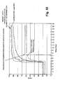
- a graph is depicted to show a comparison in a test set up of the relative humidity determination with and without the triangulation technique of the present invention.
- a goal of the present invention is to be able to accurately determine the relative humidity within 63% of the actual value within 30 seconds of data analysis.
- Fig. 10 shows that the present invention achieves this result. It should be appreciated that the present invention permits a determination of the actual temperature and humidity in the air space adjacent to the windscreen by taking measurements in an artificially heated location using discrete sensors integrated into a signal, high density module.
Landscapes
- Physics & Mathematics (AREA)
- Thermal Sciences (AREA)
- Engineering & Computer Science (AREA)
- Mechanical Engineering (AREA)
- General Physics & Mathematics (AREA)
- Air-Conditioning For Vehicles (AREA)
Abstract
Description
- The present invention is directed to a vehicle heating ventilation air conditioning ("HVAC") system and is particularly directed to a method and apparatus for determining temperature and relative humidity for use in a vehicle HVAC system.
- A vehicle HVAC system is used to control the comfort level, e.g., temperature and humidity, within the vehicle cabin for the vehicle occupants. HVAC systems may allow the operator to manually set various operating parameters such as the ON/OFF state of the air conditioner, a desired temperature setting, a blower speed, airflow direction, the amount of air flow at the feet, the window, etc. Other vehicle HVAC systems use minimal operator input information, e.g., an operator desired temperature setting, and the remainder of the system parameters are automatically controlled.
- One of the functions of a vehicle HVAC system is to prevent fogging of the vehicle windscreen (windshield) during vehicle operation. The prevention of windscreen fogging requires an accurate determination of the relative humidity in the vehicle adjacent to the windscreen and the temperature of the windscreen itself. It is known to combine (integrate) several vehicle sensing systems into one module. For example, a vehicle rain sensor for windscreen wiper control may be mounted in a module that is mounted against the inside of the windscreen in front of the rearview mirror. It is also known to mount a humidity sensor and an ambient air temperature sensor in the rain sensor module. Also, it is known to mount other types of sensors in the rain sensor module such as a forward looking camera. Certain sensors, such as the camera sensor, may have an associated processor circuit that generates a significant amount of heat. Heat generated from any heat source, e.g., a camera processor or any other type of heat source, can affect sensed condition of other sensors within the module such as temperature and humidity sensors. This heating effect can result in an improper determination of relative humidity thereby resulting in improper control of the vehicle's HVAC system and fogging of the windscreen.
- The present invention is directed to a method and apparatus for determining relative humidity for a vehicle HVAC system by measuring temperature at a plurality of locations within the sensor module including at any heat source within the module and determining relative humidity using a temperature triangulation scheme. The vehicle's HVAC system is then controlled in response to the determined temperature and relative humidity in accordance with the present invention.
- In accordance with one example embodiment of the present invention, a sensor module is provided having a housing. A heat source is located within the housing of the sensor module and a plurality of temperature sensors are mounted in housing of said sensor module. At least one temperature sensors is located adjacent to the heat source and at least one other temperature sensor is spaced from the heat source. A humidity sensor is located within the housing of the sensor module. A controller is connected to the plurality of temperature sensors and to the humidity sensor for determining relative humidity and temperature at the windscreen using a regression analysis and for providing a control signal indicative thereof.
- In accordance with another aspect of the present invention, an apparatus is provided for aiding in prevention of vehicle windscreen fogging comprising a sensor module having a housing mountable to the inside of the windscreen and a heat source located within said housing of the sensor module. At least three temperature sensors are mounted in said housing of said sensor module, at least one of said temperature sensors being located adjacent to the heat source, at least another one of said temperature sensors being in thermal contact with the windscreen, and at least yet another one of said temperature sensor being spaced from said heat source and said windscreen. A humidity sensor is located within said housing of the sensor module and a controller is connected to said plurality of temperature sensors and to said humidity sensor for determining the relative humidity and temperature at the windscreen using a regression analysis and providing a control signal. A heating, ventilation, air conditioning system is operative with the windscreen of the vehicle and responsive to said control signal for controlling air flow and temperature and humidity of in-flowing air so as to aid in preventing windscreen fogging.
- In accordance with another example embodiment of the present invention, a method is provided for aiding in prevention of vehicle windscreen fogging comprising the steps of mounting a sensor module having a housing to the inside of the windscreen, locating a heat source within said housing of the sensor module, locating at least three temperature sensors in said housing of said sensor module, at least one of said temperature sensors being located adjacent to the heat source, at least another one of said temperature sensors being in thermal contact with the windscreen, and at least yet another one of said temperature sensor being spaced from said heat source and said windscreen, locating a humidity sensor within said housing of the sensor module, determining the relative humidity and temperature at the windscreen in response to signals from said temperature sensors and said humidity sensor using a regression analysis and providing a control signal in response thereto, and controlling a heating, ventilation, air conditioning system operative with the windscreen of the vehicle in response to said control signal for controlling air flow and temperature and humidity of in-flowing air so as to aid in preventing windscreen fogging.
- The foregoing and other features and advantages of the present invention will become apparent to those skilled in the art to which the present invention relates upon reading the following description with reference to the accompanying drawings, in which:
-
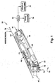
Fig. 1 is a schematic block diagram of a sensing arrangement made in accordance with one example embodiment of the present invention for determining temperature and relative humidity in a vehicle HVAC system; -
Fig. 2 is a larger schematic view of the sensor module ofFig. 1 ; -
Fig. 3 is a bottom perspective view of the sensor module ofFig. 1 ; -
Fig. 4 is a top perspective view of the sensor module ofFig. 1 ; -
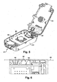
Fig. 5 is a perspective view of the sensor module ofFig. 1 with the cover in an open position; -
Fig. 6 is an enlarged side cross sectional view of a portion of the sensor module ofFig. 1 showing a windscreen temperature sensor; -
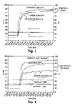
Fig. 7 is a graphical representation of the output signals from three temperature sensors when no heat source is active within the sensor module ofFig. 1 ; -
Fig. 8 is a graphical representation of the output signals from the three temperature sensors when a heat source is active within the sensor module ofFig. 1 without the temperature and humidity determinations of the present invention; -
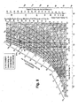
Fig. 9 is a graphical representation of a psychrometric chart used to determine certain values for use with the present invention; and -
Fig. 10 is a graphical representation of humidity output signals from three temperature and humidity sensors when a heat source is active within the sensor module ofFig. 1 with the temperature and humidity determinations in accordance with the present invention. - Referring to
Figs. 1-6 , avehicle 20 has asensor module 22 mounted to the inside of the vehicle'swindscreen 24 using, for example, a translucent bonding material. Thesensor module 22 includes a twopart housing 30 having abase portion 32 and acover 34. Thehousing 30 may be made from any of a variety of materials such as metal and specifically magnesium. Thehousing 30 encloses a plurality of operational sensors such as arain sensor 40, a forward lookingcamera 42, and an ambient light sensor 44 (Fig. 4 ). Each of theoperational sensors rain sensor 40 can be used to control vehicle wipers. Theambient light sensor 44 can be used to control the vehicle headlights. The forward lookingcamera 42 can be used as part of a lane departure warning system, a pedestrian detection system, or as part of a vehicle collision detection system. Structural details of thesensor module 22 are described in co-pending patent application toBlake et al., Serial No. 12/836,125, filed July 14, 2010 - The sensors within the
sensor module 22 may include associated signal processing circuitry. The outputs from the sensor signals, whether direct signals or processed signals, are connected to an electronic control unit ("ECU") 50 via aconnector assembly 51. The ECU 50 monitors the sensor signals and controls associatedvehicle systems 52, such as vehicle wiper, vehicle lights, lane departure warning system, actuatable restraints, pedestrian collision device, etc. In accordance with the present invention, a plurality of temperature sensors and a humidity sensor are located within thesensor module 22. The ECU 50, in accordance with the present invention, monitors the temperature sensors and humidity sensor and determines temperature, dew point, and relative humidity and controls the vehicle'sHVAC system 54 to prevent fogging of thewindscreen 24. - Certain operational elements within the
sensor module 22, such as processing circuitry associated with the sensor(s), may generate a significant amount of heat within thesensor module 22. For example, the forward lookingcamera 42 has an associatedsignal processing circuit 60 mounted on a printed circuit board ("PCB") 62 that processes the camera signal and outputs associated signals to theECU 50 for subsequent use, such as pedestrian detection, lane change warning system, etc. Theprocessing circuit 60 may generate a significant amount of heat and, thereby, acts as a heat source that can heat the interior of thesensor module 22. Any such device that generates heat within thesensor module 22 is referred to in this application as a heat source. The presence of such a heat source within thesensor module 22 can inhibit the ability of the humidity sensor and temperature sensors from providing true readings that would allow an accurate determination of the temperature, relative humidity, and dew point necessary for prevention of windscreen fogging. - The
sensor module 22, in accordance with the present invention, includes three temperature sensors and a humidity sensor located at appropriate locations within thesensor module 22 to enable determination of the true temperatures and relative humidity needed to predict/detect a fogging condition of thewindscreen 24. Specifically, awindscreen temperature sensor 64 is in thermal contact with thewindscreen 24. As can be seen inFig. 6 , thewindscreen temperature sensor 64 is embedded in a thermallyconductive compound material 66 that is in contract with thewindscreen 24 and transfers the windscreen temperature to thesensor 64. Thewindscreen temperature sensor 64 provides a signal indicative of the windscreen temperature to theECU 50. Thesensor module 22 further includes asecond temperature sensor 70 mounted adjacent to the processing circuit (heat source) 60 on thePCB 62 opposite the processing circuit. Thissecond temperature sensor 70 is referred to as the heat source temperature sensor and it provides a signal indicative of the heat source temperature to theECU 50. Thesensor module 22 further includes a humidity/temperature sensor 74 mounted in anopening 76 of thesensor module 22 so as to be exposed to ambient air. The humidity/temperature sensor 74 senses the humidity level of the air within thevehicle cabin 78 and provides a humidity signal indicative thereof to theECU 50. Also, the humidity/temperature sensor 74 senses the cabin temperature and provides a temperature signal indicative thereof to theECU 50. If theheat source 60 is operating, i.e., energized, and affecting the temperature within thesensor module 22, the temperature signal from the humidity/temperature sensor 74 will have an error value attributable to theheat source 60. - Referring to
Figs. 7 and 8 , the temperature and relative humidity measurement and determination problem resulting from the presence of theheat source 60 in thesensor module 22 will be appreciated. The graphs ofFigs. 7 and 8 show a test set up that monitors the temperature within the sensor module and at the output of the defroster vent of the vehicle for illustration purposes and a graphical representation of the measured relative humidity of the module, at the defroster vent and within the vehicle cabin for illustration purposes. The graph ofFig. 7 shows the sensed temperature of the sensor module when theheat source 60 is not active. Note that the module temperature is the same as the sensed temperature at the defroster vent in this test set up. The relative humidity value based on the sensed temperature at the defrost vent, themodule 22, and within the vehicle cabin shows a small delta when the heat source is not on. Referring toFig. 8 , the module temperature is shown when theheat source 60 is active. Note that the module temperature is greater than the temperature at the defroster vent due to the heating of the module from the heat source. The relative humidity values with the heat source on shows a large delta in the measured temperature readings and the determined relative humidity. The self-heating effect of the integrated module results in an increase in temperature at the point of measurement and a reduction in the amount of relative humidity. - In accordance with the present invention, a triangulation technique along with regression analysis is used on the sensor signals from the three temperature sensor signals and the humidity sensor signal so as to accurately predict/detect a fogging condition of the windscreen. A linear equation can be utilized to calculate actual temperature at the windscreen by triangulating three available temperatures. The coefficients of this linear equation can be obtained via a regression analysis over the
sensor module 22 operating range. - A linear triangulation,, in accordance with one example embodiment of the present invention, to determine windscreen temperature is:

assuming all temperatures are measured in degrees C. For a measuredhumidity sensor 74 temperature Ts and a triangulated windscreen temperature Tw, the relative humidity at windscreen φw can be calculated from the measured relative humidity atsensor 74 φs through the following relation:
where Pg (Ts) and Pg (Tw) are the water vapor saturation pressure at Ts and Tw respectively. Using the psychrometric chart ofFig. 9 or using any of the following equations:


the water vapor saturation can be calculated for a given temperature. In accordance with the present invention, the sensed temperatures are used to predict the windscreen temperature. TheECU 50 does the determinations and makes humidity corrections and adjustments based on water vapor pressure relationships to prevent windscreen fogging. These several equations are used to convert the manual psychrometric chart ofFig. 9 into a more useful format. - Referring to
Fig. 10 , a graph is depicted to show a comparison in a test set up of the relative humidity determination with and without the triangulation technique of the present invention. A goal of the present invention is to be able to accurately determine the relative humidity within 63% of the actual value within 30 seconds of data analysis.Fig. 10 shows that the present invention achieves this result. It should be appreciated that the present invention permits a determination of the actual temperature and humidity in the air space adjacent to the windscreen by taking measurements in an artificially heated location using discrete sensors integrated into a signal, high density module. - From the above description of the invention, those skilled in the art will perceive improvements, changes and modifications. Such improvements, changes and modifications within the skill of the art are intended to be covered by the appended claims.
Claims (6)
- A sensor module comprising:a housing;a heat source located within the housing of the sensor module;a plurality of temperature sensors mounted in housing of said sensor module, at least one temperature sensor located adjacent to said heat source and at least one other temperature sensor spaced from said heat source;a humidity sensor located within said housing of said module; anda controller connected to said plurality of temperature sensors and to said humidity sensor for determining relative humidity and temperature at the windscreen using a regression analysis and for providing a control signal indicative thereof.
- The sensor module of claim 1 wherein said plurality of temperature sensors includes at least three temperature sensors and said regression analysis includes temperature triangulation.
- The sensor module of claim 2 wherein said sensor module is mounted against a glass surface and wherein at least one of said temperature sensors measures the temperature of said glass.
- The sensor module of claim 3 wherein said controller is connected to a heating ventilation and air conditioning unit and control said unit in response to determined relative humidity and temperature so as to aid in preventing fogging of said glass surface.
- An apparatus for aiding in prevention of vehicle windscreen fogging comprising:a sensor module having a housing mountable to the inside of the windscreen;a heat source located within said housing of the sensor module;at least three temperature sensors mounted in said housing of said sensor module, at least one of said temperature sensors located adjacent to said heat source, at least another one of said temperature sensors being in thermal contact with the windscreen, and at least yet another one of said temperature sensor spaced from said heat source and said windscreen;a humidity sensor located within said housing of the sensor module;a controller connected to said plurality of temperature sensors and to said humidity sensor for determining the relative humidity and temperature at the windscreen using a regression analysis and providing a control signal; anda heating, ventilation, air conditioning system operative with the windscreen of the vehicle and responsive to said control signal for controlling air flow and temperature and humidity of in-flowing air so as to aid in preventing windscreen fogging.
- A method for aiding in prevention of vehicle windscreen fogging comprising the steps of:mounting a sensor module having a housing to the inside of the windscreen;locating a heat source within said housing of the sensor module;locating at least three temperature sensors in said housing of said sensor module, at least one of said temperature sensors being located adjacent to said heat source, at least another one of said temperature sensors being in thermal contact with the windscreen, and at least yet another one of said temperature sensor being spaced from said heat source and said windscreen;locating a humidity sensor within said housing of the sensor module;determining the relative humidity and temperature at the windscreen in response to signals from said temperature sensors and said humidity sensor using a regression analysis and providing a control signal in response thereto; andcontrolling a heating, ventilation, air conditioning system operative with the windscreen of the vehicle in response to said control signal for controlling air flow and temperature and humidity of in-flowing air so as to aid in preventing windscreen fogging.
Applications Claiming Priority (1)
| Application Number | Priority Date | Filing Date | Title |
|---|---|---|---|
| US12/851,578 US9415662B2 (en) | 2010-08-06 | 2010-08-06 | Method and apparatus for determining temperature and relative humidity for use in a vehicle HVAC system |
Publications (2)
| Publication Number | Publication Date |
|---|---|
| EP2415623A1 true EP2415623A1 (en) | 2012-02-08 |
| EP2415623B1 EP2415623B1 (en) | 2013-03-20 |
Family
ID=44851712
Family Applications (1)
| Application Number | Title | Priority Date | Filing Date |
|---|---|---|---|
| EP11006395A Not-in-force EP2415623B1 (en) | 2010-08-06 | 2011-08-03 | Method and apparatus for determining temperature and relative humidity for use in a vehicle HVAC system |
Country Status (3)
| Country | Link |
|---|---|
| US (1) | US9415662B2 (en) |
| EP (1) | EP2415623B1 (en) |
| ES (1) | ES2405755T3 (en) |
Cited By (1)
| Publication number | Priority date | Publication date | Assignee | Title |
|---|---|---|---|---|
| EP3249590A1 (en) * | 2016-05-26 | 2017-11-29 | The Boeing Company | Health evaluation and prognostic method for non-monotonic dependent parameters |
Families Citing this family (12)
| Publication number | Priority date | Publication date | Assignee | Title |
|---|---|---|---|---|
| DE102013019305B4 (en) | 2013-11-16 | 2024-10-02 | HELLA GmbH & Co. KGaA | Method and device for determining at least one control signal for controlling an air conditioning device and vehicle therewith |
| KR101962700B1 (en) * | 2013-12-24 | 2019-03-28 | 주식회사 만도 | System and method for lane recognition using defog sensor |
| JP6575248B2 (en) | 2014-10-16 | 2019-09-18 | 株式会社デンソー | Anti-fog device |
| FR3035177B1 (en) * | 2015-04-16 | 2022-10-07 | Valeo Vision | CONTROL DEVICE FOR A VEHICLE LIGHTING AND/OR SIGNALING SYSTEM |
| JP6390512B2 (en) * | 2015-05-21 | 2018-09-19 | 株式会社デンソー | In-vehicle camera device |
| US10288986B2 (en) | 2017-02-22 | 2019-05-14 | Trw Automotive U.S. Llc | Moderation of a driver assist camera enhancement via a vehicle windshield |
| DE112018005175T5 (en) * | 2017-11-03 | 2020-07-02 | ZF Active Safety and Electronices U.S. LLC | Driving support system |
| DE102018113230A1 (en) * | 2018-06-04 | 2019-12-05 | Bcs Automotive Interface Solutions Gmbh | sensor module |
| JP7546382B2 (en) * | 2020-06-02 | 2024-09-06 | 株式会社Subaru | Vehicle-mounted camera device |
| JP7415877B2 (en) * | 2020-11-06 | 2024-01-17 | 株式会社デンソー | Raindrop detection device |
| DE102023131230A1 (en) * | 2023-11-10 | 2025-05-15 | Valeo Schalter Und Sensoren Gmbh | DEVICE FOR A VEHICLE |
| KR20250109317A (en) * | 2024-01-10 | 2025-07-17 | 현대자동차주식회사 | Sensor defog sensor |
Citations (4)
| Publication number | Priority date | Publication date | Assignee | Title |
|---|---|---|---|---|
| US6422062B1 (en) * | 2000-08-29 | 2002-07-23 | Delphi Technologies, Inc. | Integrated glass fog sensor unit |
| WO2006029901A1 (en) * | 2004-09-15 | 2006-03-23 | Magna Donnelly Electronics Naas Limited | An environmental control system for a vehicle |
| US20060289458A1 (en) * | 2005-05-17 | 2006-12-28 | Halla Climate Control Corporation | Fogging detecting system for an automotive vehicle and method for controlling the system |
| US20080066477A1 (en) * | 2006-09-15 | 2008-03-20 | Denso Corporation | Humidity detecting apparatus and vehicular air conditioner having the same |
Family Cites Families (12)
| Publication number | Priority date | Publication date | Assignee | Title |
|---|---|---|---|---|
| ITTO20020457A1 (en) | 2002-05-29 | 2003-12-01 | C R F Societa Con Sortile Per | DEVICE AND METHOD FOR AUTOMATICALLY PREVENTING THE FOGING OF A VEHICLE WINDSHIELD. |
| US6108084A (en) * | 1995-08-17 | 2000-08-22 | Robert Bosch Gmbh | Combined sensor device for measuring both rain-covered area on and visual range through a windshield of a motor vehicle |
| DE60005474T2 (en) | 1999-12-23 | 2004-07-22 | Visteon Global Technologies, Inc., Dearborn | Procedure for avoiding fogging of the windshield by determining the limit moisture required for this |
| US6660360B2 (en) * | 2000-01-04 | 2003-12-09 | Cooper Technology Services, Llc | Laminate of a substrate and an extruded high density polyethylene |
| FR2806037B1 (en) | 2000-03-07 | 2002-11-15 | Valeo Electronique | DEVICE FOR DETECTING A RISK OF FOGTING A MOTOR VEHICLE WINDOW, AND INSTALLATION COMPRISING SUCH A DEVICE |
| US6824281B2 (en) * | 2002-01-31 | 2004-11-30 | Donnelly Corporation | Vehicle accessory module |
| US7313503B2 (en) * | 2002-02-19 | 2007-12-25 | Hewlett-Packard Development Company, L.P. | Designing layout for internet datacenter cooling |
| JP2004142492A (en) | 2002-10-22 | 2004-05-20 | Denso Corp | Vehicle air conditioner |
| US7446427B2 (en) * | 2003-05-20 | 2008-11-04 | Gentex Corporation | Rearview mirror system for accommodating a rain sensor |
| US7197927B2 (en) | 2004-02-16 | 2007-04-03 | Sitronic Gesellschaft für Elektrotechnische Ausrustüng mbH & Co. KG | Sensor for determining the interior humidity and fogging up tendency and fastening device of the sensor |
| US7392838B2 (en) | 2004-06-30 | 2008-07-01 | Honda Motor Co., Ltd. | System and method for vehicle defogging condition calculation and control |
| US8256821B2 (en) | 2004-12-15 | 2012-09-04 | Magna Donnelly Engineering Gmbh | Accessory module system for a vehicle window |
-
2010
- 2010-08-06 US US12/851,578 patent/US9415662B2/en not_active Expired - Fee Related
-
2011
- 2011-08-03 ES ES11006395T patent/ES2405755T3/en active Active
- 2011-08-03 EP EP11006395A patent/EP2415623B1/en not_active Not-in-force
Patent Citations (4)
| Publication number | Priority date | Publication date | Assignee | Title |
|---|---|---|---|---|
| US6422062B1 (en) * | 2000-08-29 | 2002-07-23 | Delphi Technologies, Inc. | Integrated glass fog sensor unit |
| WO2006029901A1 (en) * | 2004-09-15 | 2006-03-23 | Magna Donnelly Electronics Naas Limited | An environmental control system for a vehicle |
| US20060289458A1 (en) * | 2005-05-17 | 2006-12-28 | Halla Climate Control Corporation | Fogging detecting system for an automotive vehicle and method for controlling the system |
| US20080066477A1 (en) * | 2006-09-15 | 2008-03-20 | Denso Corporation | Humidity detecting apparatus and vehicular air conditioner having the same |
Cited By (2)
| Publication number | Priority date | Publication date | Assignee | Title |
|---|---|---|---|---|
| EP3249590A1 (en) * | 2016-05-26 | 2017-11-29 | The Boeing Company | Health evaluation and prognostic method for non-monotonic dependent parameters |
| US10124752B2 (en) | 2016-05-26 | 2018-11-13 | The Boeing Company | Health evaluation and prognostic method for non-monotonic dependent parameters |
Also Published As
| Publication number | Publication date |
|---|---|
| US9415662B2 (en) | 2016-08-16 |
| US20120034857A1 (en) | 2012-02-09 |
| EP2415623B1 (en) | 2013-03-20 |
| ES2405755T3 (en) | 2013-06-03 |
Similar Documents
| Publication | Publication Date | Title |
|---|---|---|
| EP2415623B1 (en) | Method and apparatus for determining temperature and relative humidity for use in a vehicle HVAC system | |
| US7197927B2 (en) | Sensor for determining the interior humidity and fogging up tendency and fastening device of the sensor | |
| US7690421B2 (en) | Low humidity detection system and method thereof | |
| CN100570297C (en) | Glass temperature detecting system, window fog detecting system and method and vehicle air conditioner | |
| US7866169B2 (en) | System and method for vehicle defogging condition calculation and control | |
| CN103057380B (en) | Avoid being formed the method and device of fog on the glass pane of vehicle | |
| US8733428B2 (en) | Air conditioning system for vehicle | |
| US6809530B2 (en) | Sensor for detecting condensation and use in a sensor module | |
| US7845182B2 (en) | Fan control limitation logic in auto defog system | |
| US20180117988A1 (en) | Automatic vehicular defogging system | |
| US7102501B2 (en) | Device and method for automatically preventing misting of the windscreen of a vehicle | |
| US20060063120A1 (en) | Sensor unit device and method for avoiding condensation on a surface | |
| US7416331B2 (en) | Condensation sensor | |
| JP2005531776A5 (en) | ||
| EP1564044B1 (en) | Mounting means with a sensor for determining the humidity and incipient fogging in a compartment | |
| JP3975200B2 (en) | Method for preventing fogging of automobile wind glass | |
| KR20070004659A (en) | Temperature sensors and devices for in-vehicle climate control | |
| KR20050114014A (en) | Apparatus for detecting a window fogging status | |
| JP3743544B2 (en) | Gas detector | |
| CN120287789A (en) | Automatic defogging sensor | |
| JPS6162852A (en) | Humidity detector for automobile | |
| KR20040073218A (en) | Apparatus removing dampness on the car window and the operating method | |
| KR20030025736A (en) | Humidity sensing module for an automobile using dew point | |
| KR20000039346A (en) | Apparatus for automatically controlling interior humidity of vehicle | |
| KR970061658A (en) | Automotive air conditioning system with windshield protection |
Legal Events
| Date | Code | Title | Description |
|---|---|---|---|
| 17P | Request for examination filed |
Effective date: 20110803 |
|
| AK | Designated contracting states |
Kind code of ref document: A1 Designated state(s): AL AT BE BG CH CY CZ DE DK EE ES FI FR GB GR HR HU IE IS IT LI LT LU LV MC MK MT NL NO PL PT RO RS SE SI SK SM TR |
|
| AX | Request for extension of the european patent |
Extension state: BA ME |
|
| PUAI | Public reference made under article 153(3) epc to a published international application that has entered the european phase |
Free format text: ORIGINAL CODE: 0009012 |
|
| RIC1 | Information provided on ipc code assigned before grant |
Ipc: B60H 1/00 20060101AFI20120807BHEP |
|
| GRAP | Despatch of communication of intention to grant a patent |
Free format text: ORIGINAL CODE: EPIDOSNIGR1 |
|
| GRAS | Grant fee paid |
Free format text: ORIGINAL CODE: EPIDOSNIGR3 |
|
| GRAA | (expected) grant |
Free format text: ORIGINAL CODE: 0009210 |
|
| AK | Designated contracting states |
Kind code of ref document: B1 Designated state(s): AL AT BE BG CH CY CZ DE DK EE ES FI FR GB GR HR HU IE IS IT LI LT LU LV MC MK MT NL NO PL PT RO RS SE SI SK SM TR |
|
| REG | Reference to a national code |
Ref country code: GB Ref legal event code: FG4D |
|
| REG | Reference to a national code |
Ref country code: CH Ref legal event code: EP |
|
| REG | Reference to a national code |
Ref country code: IE Ref legal event code: FG4D |
|
| REG | Reference to a national code |
Ref country code: AT Ref legal event code: REF Ref document number: 601844 Country of ref document: AT Kind code of ref document: T Effective date: 20130415 |
|
| REG | Reference to a national code |
Ref country code: DE Ref legal event code: R096 Ref document number: 602011001069 Country of ref document: DE Effective date: 20130516 |
|
| REG | Reference to a national code |
Ref country code: ES Ref legal event code: FG2A Ref document number: 2405755 Country of ref document: ES Kind code of ref document: T3 Effective date: 20130603 |
|
| PG25 | Lapsed in a contracting state [announced via postgrant information from national office to epo] |
Ref country code: NO Free format text: LAPSE BECAUSE OF FAILURE TO SUBMIT A TRANSLATION OF THE DESCRIPTION OR TO PAY THE FEE WITHIN THE PRESCRIBED TIME-LIMIT Effective date: 20130620 Ref country code: BG Free format text: LAPSE BECAUSE OF FAILURE TO SUBMIT A TRANSLATION OF THE DESCRIPTION OR TO PAY THE FEE WITHIN THE PRESCRIBED TIME-LIMIT Effective date: 20130620 Ref country code: LT Free format text: LAPSE BECAUSE OF FAILURE TO SUBMIT A TRANSLATION OF THE DESCRIPTION OR TO PAY THE FEE WITHIN THE PRESCRIBED TIME-LIMIT Effective date: 20130320 Ref country code: SE Free format text: LAPSE BECAUSE OF FAILURE TO SUBMIT A TRANSLATION OF THE DESCRIPTION OR TO PAY THE FEE WITHIN THE PRESCRIBED TIME-LIMIT Effective date: 20130320 |
|
| REG | Reference to a national code |
Ref country code: AT Ref legal event code: MK05 Ref document number: 601844 Country of ref document: AT Kind code of ref document: T Effective date: 20130320 |
|
| REG | Reference to a national code |
Ref country code: LT Ref legal event code: MG4D |
|
| PG25 | Lapsed in a contracting state [announced via postgrant information from national office to epo] |
Ref country code: SI Free format text: LAPSE BECAUSE OF FAILURE TO SUBMIT A TRANSLATION OF THE DESCRIPTION OR TO PAY THE FEE WITHIN THE PRESCRIBED TIME-LIMIT Effective date: 20130320 Ref country code: FI Free format text: LAPSE BECAUSE OF FAILURE TO SUBMIT A TRANSLATION OF THE DESCRIPTION OR TO PAY THE FEE WITHIN THE PRESCRIBED TIME-LIMIT Effective date: 20130320 Ref country code: GR Free format text: LAPSE BECAUSE OF FAILURE TO SUBMIT A TRANSLATION OF THE DESCRIPTION OR TO PAY THE FEE WITHIN THE PRESCRIBED TIME-LIMIT Effective date: 20130621 Ref country code: LV Free format text: LAPSE BECAUSE OF FAILURE TO SUBMIT A TRANSLATION OF THE DESCRIPTION OR TO PAY THE FEE WITHIN THE PRESCRIBED TIME-LIMIT Effective date: 20130320 |
|
| REG | Reference to a national code |
Ref country code: NL Ref legal event code: VDEP Effective date: 20130320 |
|
| PG25 | Lapsed in a contracting state [announced via postgrant information from national office to epo] |
Ref country code: RS Free format text: LAPSE BECAUSE OF FAILURE TO SUBMIT A TRANSLATION OF THE DESCRIPTION OR TO PAY THE FEE WITHIN THE PRESCRIBED TIME-LIMIT Effective date: 20130320 Ref country code: BE Free format text: LAPSE BECAUSE OF FAILURE TO SUBMIT A TRANSLATION OF THE DESCRIPTION OR TO PAY THE FEE WITHIN THE PRESCRIBED TIME-LIMIT Effective date: 20130320 Ref country code: HR Free format text: LAPSE BECAUSE OF FAILURE TO SUBMIT A TRANSLATION OF THE DESCRIPTION OR TO PAY THE FEE WITHIN THE PRESCRIBED TIME-LIMIT Effective date: 20130320 |
|
| PG25 | Lapsed in a contracting state [announced via postgrant information from national office to epo] |
Ref country code: SK Free format text: LAPSE BECAUSE OF FAILURE TO SUBMIT A TRANSLATION OF THE DESCRIPTION OR TO PAY THE FEE WITHIN THE PRESCRIBED TIME-LIMIT Effective date: 20130320 Ref country code: CZ Free format text: LAPSE BECAUSE OF FAILURE TO SUBMIT A TRANSLATION OF THE DESCRIPTION OR TO PAY THE FEE WITHIN THE PRESCRIBED TIME-LIMIT Effective date: 20130320 Ref country code: PT Free format text: LAPSE BECAUSE OF FAILURE TO SUBMIT A TRANSLATION OF THE DESCRIPTION OR TO PAY THE FEE WITHIN THE PRESCRIBED TIME-LIMIT Effective date: 20130722 Ref country code: NL Free format text: LAPSE BECAUSE OF FAILURE TO SUBMIT A TRANSLATION OF THE DESCRIPTION OR TO PAY THE FEE WITHIN THE PRESCRIBED TIME-LIMIT Effective date: 20130320 Ref country code: AT Free format text: LAPSE BECAUSE OF FAILURE TO SUBMIT A TRANSLATION OF THE DESCRIPTION OR TO PAY THE FEE WITHIN THE PRESCRIBED TIME-LIMIT Effective date: 20130320 Ref country code: IS Free format text: LAPSE BECAUSE OF FAILURE TO SUBMIT A TRANSLATION OF THE DESCRIPTION OR TO PAY THE FEE WITHIN THE PRESCRIBED TIME-LIMIT Effective date: 20130720 Ref country code: EE Free format text: LAPSE BECAUSE OF FAILURE TO SUBMIT A TRANSLATION OF THE DESCRIPTION OR TO PAY THE FEE WITHIN THE PRESCRIBED TIME-LIMIT Effective date: 20130320 Ref country code: RO Free format text: LAPSE BECAUSE OF FAILURE TO SUBMIT A TRANSLATION OF THE DESCRIPTION OR TO PAY THE FEE WITHIN THE PRESCRIBED TIME-LIMIT Effective date: 20130320 |
|
| PG25 | Lapsed in a contracting state [announced via postgrant information from national office to epo] |
Ref country code: PL Free format text: LAPSE BECAUSE OF FAILURE TO SUBMIT A TRANSLATION OF THE DESCRIPTION OR TO PAY THE FEE WITHIN THE PRESCRIBED TIME-LIMIT Effective date: 20130320 Ref country code: CY Free format text: LAPSE BECAUSE OF FAILURE TO SUBMIT A TRANSLATION OF THE DESCRIPTION OR TO PAY THE FEE WITHIN THE PRESCRIBED TIME-LIMIT Effective date: 20130320 |
|
| PLBE | No opposition filed within time limit |
Free format text: ORIGINAL CODE: 0009261 |
|
| STAA | Information on the status of an ep patent application or granted ep patent |
Free format text: STATUS: NO OPPOSITION FILED WITHIN TIME LIMIT |
|
| PG25 | Lapsed in a contracting state [announced via postgrant information from national office to epo] |
Ref country code: DK Free format text: LAPSE BECAUSE OF FAILURE TO SUBMIT A TRANSLATION OF THE DESCRIPTION OR TO PAY THE FEE WITHIN THE PRESCRIBED TIME-LIMIT Effective date: 20130320 |
|
| 26N | No opposition filed |
Effective date: 20140102 |
|
| REG | Reference to a national code |
Ref country code: DE Ref legal event code: R097 Ref document number: 602011001069 Country of ref document: DE Effective date: 20140102 |
|
| PG25 | Lapsed in a contracting state [announced via postgrant information from national office to epo] |
Ref country code: MC Free format text: LAPSE BECAUSE OF FAILURE TO SUBMIT A TRANSLATION OF THE DESCRIPTION OR TO PAY THE FEE WITHIN THE PRESCRIBED TIME-LIMIT Effective date: 20130320 |
|
| REG | Reference to a national code |
Ref country code: IE Ref legal event code: MM4A |
|
| PG25 | Lapsed in a contracting state [announced via postgrant information from national office to epo] |
Ref country code: IE Free format text: LAPSE BECAUSE OF NON-PAYMENT OF DUE FEES Effective date: 20130803 |
|
| REG | Reference to a national code |
Ref country code: CH Ref legal event code: PL |
|
| PG25 | Lapsed in a contracting state [announced via postgrant information from national office to epo] |
Ref country code: LI Free format text: LAPSE BECAUSE OF NON-PAYMENT OF DUE FEES Effective date: 20140831 Ref country code: CH Free format text: LAPSE BECAUSE OF NON-PAYMENT OF DUE FEES Effective date: 20140831 |
|
| PG25 | Lapsed in a contracting state [announced via postgrant information from national office to epo] |
Ref country code: SM Free format text: LAPSE BECAUSE OF FAILURE TO SUBMIT A TRANSLATION OF THE DESCRIPTION OR TO PAY THE FEE WITHIN THE PRESCRIBED TIME-LIMIT Effective date: 20130320 |
|
| PG25 | Lapsed in a contracting state [announced via postgrant information from national office to epo] |
Ref country code: MT Free format text: LAPSE BECAUSE OF FAILURE TO SUBMIT A TRANSLATION OF THE DESCRIPTION OR TO PAY THE FEE WITHIN THE PRESCRIBED TIME-LIMIT Effective date: 20130320 Ref country code: TR Free format text: LAPSE BECAUSE OF FAILURE TO SUBMIT A TRANSLATION OF THE DESCRIPTION OR TO PAY THE FEE WITHIN THE PRESCRIBED TIME-LIMIT Effective date: 20130320 |
|
| PG25 | Lapsed in a contracting state [announced via postgrant information from national office to epo] |
Ref country code: MK Free format text: LAPSE BECAUSE OF FAILURE TO SUBMIT A TRANSLATION OF THE DESCRIPTION OR TO PAY THE FEE WITHIN THE PRESCRIBED TIME-LIMIT Effective date: 20130320 Ref country code: HU Free format text: LAPSE BECAUSE OF FAILURE TO SUBMIT A TRANSLATION OF THE DESCRIPTION OR TO PAY THE FEE WITHIN THE PRESCRIBED TIME-LIMIT; INVALID AB INITIO Effective date: 20110803 Ref country code: LU Free format text: LAPSE BECAUSE OF NON-PAYMENT OF DUE FEES Effective date: 20130803 |
|
| REG | Reference to a national code |
Ref country code: FR Ref legal event code: PLFP Year of fee payment: 6 |
|
| REG | Reference to a national code |
Ref country code: FR Ref legal event code: PLFP Year of fee payment: 7 |
|
| REG | Reference to a national code |
Ref country code: DE Ref legal event code: R082 Ref document number: 602011001069 Country of ref document: DE Representative=s name: PRINZ & PARTNER MBB PATENTANWAELTE RECHTSANWAE, DE |
|
| REG | Reference to a national code |
Ref country code: FR Ref legal event code: PLFP Year of fee payment: 8 |
|
| PG25 | Lapsed in a contracting state [announced via postgrant information from national office to epo] |
Ref country code: AL Free format text: LAPSE BECAUSE OF FAILURE TO SUBMIT A TRANSLATION OF THE DESCRIPTION OR TO PAY THE FEE WITHIN THE PRESCRIBED TIME-LIMIT Effective date: 20130320 |
|
| PGFP | Annual fee paid to national office [announced via postgrant information from national office to epo] |
Ref country code: ES Payment date: 20180801 Year of fee payment: 8 |
|
| PGFP | Annual fee paid to national office [announced via postgrant information from national office to epo] |
Ref country code: GB Payment date: 20180822 Year of fee payment: 8 |
|
| REG | Reference to a national code |
Ref country code: DE Ref legal event code: R082 Ref document number: 602011001069 Country of ref document: DE Representative=s name: PRINZ & PARTNER MBB PATENTANWAELTE RECHTSANWAE, DE Ref country code: DE Ref legal event code: R081 Ref document number: 602011001069 Country of ref document: DE Owner name: BCS AUTOMOTIVE INTERFACE SOLUTIONS US LLC, WIL, US Free format text: FORMER OWNER: TRW AUTOMOTIVE U.S. LLC, LIVONIA, MICH., US |
|
| PGFP | Annual fee paid to national office [announced via postgrant information from national office to epo] |
Ref country code: IT Payment date: 20190829 Year of fee payment: 9 Ref country code: FR Payment date: 20190822 Year of fee payment: 9 Ref country code: DE Payment date: 20190816 Year of fee payment: 9 |
|
| GBPC | Gb: european patent ceased through non-payment of renewal fee |
Effective date: 20190803 |
|
| PG25 | Lapsed in a contracting state [announced via postgrant information from national office to epo] |
Ref country code: GB Free format text: LAPSE BECAUSE OF NON-PAYMENT OF DUE FEES Effective date: 20190803 |
|
| REG | Reference to a national code |
Ref country code: ES Ref legal event code: FD2A Effective date: 20210105 |
|
| PG25 | Lapsed in a contracting state [announced via postgrant information from national office to epo] |
Ref country code: ES Free format text: LAPSE BECAUSE OF NON-PAYMENT OF DUE FEES Effective date: 20190804 |
|
| REG | Reference to a national code |
Ref country code: DE Ref legal event code: R119 Ref document number: 602011001069 Country of ref document: DE |
|
| PG25 | Lapsed in a contracting state [announced via postgrant information from national office to epo] |
Ref country code: DE Free format text: LAPSE BECAUSE OF NON-PAYMENT OF DUE FEES Effective date: 20210302 Ref country code: IT Free format text: LAPSE BECAUSE OF NON-PAYMENT OF DUE FEES Effective date: 20200803 Ref country code: FR Free format text: LAPSE BECAUSE OF NON-PAYMENT OF DUE FEES Effective date: 20200831 |