EP2415419A1 - Stopper housing case - Google Patents
Stopper housing case Download PDFInfo
- Publication number
- EP2415419A1 EP2415419A1 EP11006236A EP11006236A EP2415419A1 EP 2415419 A1 EP2415419 A1 EP 2415419A1 EP 11006236 A EP11006236 A EP 11006236A EP 11006236 A EP11006236 A EP 11006236A EP 2415419 A1 EP2415419 A1 EP 2415419A1
- Authority
- EP
- European Patent Office
- Prior art keywords
- stopper
- drill
- blade
- concave
- housing case
- Prior art date
- Legal status (The legal status is an assumption and is not a legal conclusion. Google has not performed a legal analysis and makes no representation as to the accuracy of the status listed.)
- Withdrawn
Links
- 238000003780 insertion Methods 0.000 claims abstract description 57
- 230000037431 insertion Effects 0.000 claims abstract description 57
- 239000004053 dental implant Substances 0.000 claims abstract description 26
- 238000011282 treatment Methods 0.000 claims abstract description 13
- 239000000463 material Substances 0.000 claims abstract description 5
- 230000002093 peripheral effect Effects 0.000 claims description 7
- 230000000149 penetrating effect Effects 0.000 description 2
- 229910001069 Ti alloy Inorganic materials 0.000 description 1
- RTAQQCXQSZGOHL-UHFFFAOYSA-N Titanium Chemical compound [Ti] RTAQQCXQSZGOHL-UHFFFAOYSA-N 0.000 description 1
- 210000000988 bone and bone Anatomy 0.000 description 1
- 229910052751 metal Inorganic materials 0.000 description 1
- 239000002184 metal Substances 0.000 description 1
- 238000000034 method Methods 0.000 description 1
- 238000010883 osseointegration Methods 0.000 description 1
- 239000010936 titanium Substances 0.000 description 1
- 229910052719 titanium Inorganic materials 0.000 description 1
Images
Classifications
-
- A—HUMAN NECESSITIES
- A61—MEDICAL OR VETERINARY SCIENCE; HYGIENE
- A61B—DIAGNOSIS; SURGERY; IDENTIFICATION
- A61B90/00—Instruments, implements or accessories specially adapted for surgery or diagnosis and not covered by any of the groups A61B1/00 - A61B50/00, e.g. for luxation treatment or for protecting wound edges
- A61B90/03—Automatic limiting or abutting means, e.g. for safety
-
- A—HUMAN NECESSITIES
- A61—MEDICAL OR VETERINARY SCIENCE; HYGIENE
- A61C—DENTISTRY; APPARATUS OR METHODS FOR ORAL OR DENTAL HYGIENE
- A61C19/00—Dental auxiliary appliances
- A61C19/02—Protective casings, e.g. boxes for instruments; Bags
-
- A—HUMAN NECESSITIES
- A61—MEDICAL OR VETERINARY SCIENCE; HYGIENE
- A61B—DIAGNOSIS; SURGERY; IDENTIFICATION
- A61B50/00—Containers, covers, furniture or holders specially adapted for surgical or diagnostic appliances or instruments, e.g. sterile covers
- A61B50/30—Containers specially adapted for packaging, protecting, dispensing, collecting or disposing of surgical or diagnostic appliances or instruments
-
- A—HUMAN NECESSITIES
- A61—MEDICAL OR VETERINARY SCIENCE; HYGIENE
- A61C—DENTISTRY; APPARATUS OR METHODS FOR ORAL OR DENTAL HYGIENE
- A61C1/00—Dental machines for boring or cutting ; General features of dental machines or apparatus, e.g. hand-piece design
- A61C1/08—Machine parts specially adapted for dentistry
- A61C1/082—Positioning or guiding, e.g. of drills
- A61C1/084—Positioning or guiding, e.g. of drills of implanting tools
-
- A—HUMAN NECESSITIES
- A61—MEDICAL OR VETERINARY SCIENCE; HYGIENE
- A61C—DENTISTRY; APPARATUS OR METHODS FOR ORAL OR DENTAL HYGIENE
- A61C3/00—Dental tools or instruments
- A61C3/02—Tooth drilling or cutting instruments; Instruments acting like a sandblast machine
-
- A—HUMAN NECESSITIES
- A61—MEDICAL OR VETERINARY SCIENCE; HYGIENE
- A61C—DENTISTRY; APPARATUS OR METHODS FOR ORAL OR DENTAL HYGIENE
- A61C3/00—Dental tools or instruments
- A61C3/04—Supports for holding tooth drills in order of use
-
- A—HUMAN NECESSITIES
- A61—MEDICAL OR VETERINARY SCIENCE; HYGIENE
- A61C—DENTISTRY; APPARATUS OR METHODS FOR ORAL OR DENTAL HYGIENE
- A61C5/00—Filling or capping teeth
- A61C5/40—Implements for surgical treatment of the roots or nerves of the teeth; Nerve needles; Methods or instruments for medication of the roots
- A61C5/44—Means for controlling working depth, e.g. supports or boxes with depth-gauging means, stop positioners or files with adjustably-mounted handles
-
- A—HUMAN NECESSITIES
- A61—MEDICAL OR VETERINARY SCIENCE; HYGIENE
- A61C—DENTISTRY; APPARATUS OR METHODS FOR ORAL OR DENTAL HYGIENE
- A61C8/00—Means to be fixed to the jaw-bone for consolidating natural teeth or for fixing dental prostheses thereon; Dental implants; Implanting tools
- A61C8/0089—Implanting tools or instruments
-
- A—HUMAN NECESSITIES
- A61—MEDICAL OR VETERINARY SCIENCE; HYGIENE
- A61B—DIAGNOSIS; SURGERY; IDENTIFICATION
- A61B17/00—Surgical instruments, devices or methods
- A61B17/16—Instruments for performing osteoclasis; Drills or chisels for bones; Trepans
- A61B17/1662—Instruments for performing osteoclasis; Drills or chisels for bones; Trepans for particular parts of the body
- A61B17/1673—Instruments for performing osteoclasis; Drills or chisels for bones; Trepans for particular parts of the body for the jaw
-
- A—HUMAN NECESSITIES
- A61—MEDICAL OR VETERINARY SCIENCE; HYGIENE
- A61B—DIAGNOSIS; SURGERY; IDENTIFICATION
- A61B17/00—Surgical instruments, devices or methods
- A61B17/16—Instruments for performing osteoclasis; Drills or chisels for bones; Trepans
- A61B17/17—Guides or aligning means for drills, mills, pins or wires
- A61B17/1739—Guides or aligning means for drills, mills, pins or wires specially adapted for particular parts of the body
- A61B17/176—Guides or aligning means for drills, mills, pins or wires specially adapted for particular parts of the body for the jaw
-
- A—HUMAN NECESSITIES
- A61—MEDICAL OR VETERINARY SCIENCE; HYGIENE
- A61B—DIAGNOSIS; SURGERY; IDENTIFICATION
- A61B50/00—Containers, covers, furniture or holders specially adapted for surgical or diagnostic appliances or instruments, e.g. sterile covers
- A61B2050/005—Containers, covers, furniture or holders specially adapted for surgical or diagnostic appliances or instruments, e.g. sterile covers with a lid or cover
- A61B2050/0058—Containers, covers, furniture or holders specially adapted for surgical or diagnostic appliances or instruments, e.g. sterile covers with a lid or cover closable by translation
- A61B2050/0059—Containers, covers, furniture or holders specially adapted for surgical or diagnostic appliances or instruments, e.g. sterile covers with a lid or cover closable by translation parallel to the lid plane
-
- A—HUMAN NECESSITIES
- A61—MEDICAL OR VETERINARY SCIENCE; HYGIENE
- A61B—DIAGNOSIS; SURGERY; IDENTIFICATION
- A61B50/00—Containers, covers, furniture or holders specially adapted for surgical or diagnostic appliances or instruments, e.g. sterile covers
- A61B50/30—Containers specially adapted for packaging, protecting, dispensing, collecting or disposing of surgical or diagnostic appliances or instruments
- A61B2050/3008—Containers specially adapted for packaging, protecting, dispensing, collecting or disposing of surgical or diagnostic appliances or instruments having multiple compartments
-
- A—HUMAN NECESSITIES
- A61—MEDICAL OR VETERINARY SCIENCE; HYGIENE
- A61B—DIAGNOSIS; SURGERY; IDENTIFICATION
- A61B90/00—Instruments, implements or accessories specially adapted for surgery or diagnosis and not covered by any of the groups A61B1/00 - A61B50/00, e.g. for luxation treatment or for protecting wound edges
- A61B90/03—Automatic limiting or abutting means, e.g. for safety
- A61B2090/033—Abutting means, stops, e.g. abutting on tissue or skin
- A61B2090/034—Abutting means, stops, e.g. abutting on tissue or skin abutting on parts of the device itself
Definitions
- the present invention relates to a stopper housing case capable of housing a plurality of stoppers for defining a drill blade entering depth.
- the stopper has a cylindrical shape to be fitted on a drill from the blade edge side of a blade part, where the drill is to bore a dental implant fixture embedding hole having a predetermined depth at a jawbone when performing a dental implant treatment.
- the stopper further has a spring-like locking part to be locked with a flange part projected from a shank part of the drill.
- the stopper housing case is capable of easily attaching and detaching the stopper to and from the drill attached to a dental handpiece.
- a dental implant treatment has been broadly used as one of dental prosthesis treatments.
- a dental implant fixture made of titanium or a titanium alloy having excellent biocompatibility is embedded in a jawbone of a lost toothpart, and is substituted through direct bone bonding (osseointegration) instead of a natural tooth root.
- the dental implant fixture used in the dental implant treatment is configured separately from an abutment for fixing a dental prosthesis, or is configured integrally with the abutment.
- a stopper for defining the boring depth is attached to the drill for boring the dental implant fixture embedding hole at the jawbone .
- a method to attach the stopper at a predetermined position of a blade part of the drill with a screw or the like has been used (e. g. , refer to Japanese Translation of PCT Application Laid-Open No. 2003-501135 ).
- the attachment position must be adjusted at an every attachment operation, it is troublesome. Further, there is a problem that an accident that the stopper is moved could occur if the stopper is not fixed certainly with the screw.
- a flange part is provided to project from a shank part of a drill for boring a dental implant fixture embedding hole having a predetermined depth at a jawbone when performing a dental implant fixture treatment.
- a spring-like locking part provided at a stopper for defining a drill blade entering depth is locked with the flange part.
- the stopper has a cylindrical shape to be fitted on the drill from the blade edge side of a blade part, and has a spring-like locking part to be locked with the flange part projected from the shank part of the drill.
- the spring-like locking part of the stopper when the spring-like locking part of the stopper is locked with the flange part projected from the shank part of the drill, the spring-like locking part must be locked with the flange part so as not to be easily detached from the flange part projected from the shank part of the drill.
- strong force is necessary for locking the spring-like locking part of the stopper with the flange part projected from the shank part.
- An obj ective of the present invention is to provide a stopper housing case capable of housing a plurality of prepared stoppers and easily attaching and detaching the stoppers to and from a drill attached to a dental handpiece.
- the stopper housing case for housing a plurality of stoppers for defining a drill blade entering depth is formed with a hard material.
- the stopper has a cylindrical shape to be fitted on a drill from the blade edge side of a blade part, where the drill is to bore a dental implant fixture embedding hole having a predetermined depth at a jawbone when performing a dental implant treatment.
- the stopper has a spring-like locking part to be locked with a flange part projected from a shank part of the drill.
- the stopper housing case has the following configuration.
- Concave parts capable of respectively housing the stopper are arranged in parallel.
- Each of the concave parts includes, at one side, a flange part insertion path having a size preventing the spring-like locking part of the stopper from falling out and capable of inserting the flange part projected from the shank part of the drill.
- each of the concave parts includes, at another side opposite to the one side, a drill blade part insertion path capable of inserting the blade part of the drill.
- a stopper housing case is formed with a hard material to house a plurality of stoppers for defining a drill blade entering depth.
- the stopper has a cylindrical shape to be fitted on a drill from the blade edge side of a blade part, where the drill is to bore a dental implant fixture embedding hole having a predetermined depth at a jawbone when performing a dental implant treatment.
- the stopper has a spring-like locking part to be locked with a flange part projected from a shank part of the drill.
- each of the concave parts capable of respectively housing the stoppers are arranged in parallel.
- Each of the concave parts includes, at one side, a flange part insertion path having a size preventing the spring-like locking part of the stopper from falling out and capable of inserting the flange part projected from the shank part of the drill.
- each of the concave parts includes, at another side opposite to the one side, a drill blade part insertion path capable of inserting the blade part of the drill.
- the stopper housing case having the aforementioned configuration when end parts at the drill blade part insertion path side of the concave parts are provided so as to align together, the flange part insertion path side of the stopper housing case comes to be in a projecting state corresponding to the lengths of the stoppers. Since the stopper can be thus selected easily, it is preferable.
- projections to be engaged with a concave groove formed on an outer peripheral face of the stopper are provided on an inner face of the flange part insertion path in the concave part, the stopper can be housed stably in the stopper housing case.
- the stopper housing case further includes slide guide parts and a cap
- the stoppers can be stably stored in the stopper housing case without falling out of the stopper housing case at a time of not using the stoppers, so that it is preferable.
- the slide guide parts are provided on both side faces in parallel with the drill blade part insertion paths in the stopper housing case.
- the cap includes guide parts provided on both side parts of an inner face of the cap along the slide guide parts to slide-engage with the slide guide parts. With this configuration, the cap prevent the stoppers housed in the concave parts from falling out of the concave part.
- a stopper housing case is formed with a hard material for housing a plurality of stoppers for defining a drill blade entering depth.
- the stopper has a cylindrical shape to be fitted on a drill from the blade edge side of a blade part, where the drill is to bore a dental implant fixture embedding hole having a predetermined depth at a jawbone when performing a dental implant treatment.
- the stopper has the spring-like locking part to be locked with a flange part projected from a shank part of the drill.
- the concave parts capable of respectively housing the stoppers are arranged in parallel.
- Each of the concave parts includes, at one side, a flange part insertion path having a size preventing the spring-like locking part of the stopper from falling out and capable of inserting the flange part projected from the shank part of the drill. Further, each of the concave parts includes, at another side opposite to the one side, the drill blade part insertion path capable of inserting the blade part of the drill. According to this configuration, when the stopper is mounted on the drill attached to the dental handpiece, the drill attached to the dental handpiece is moved toward the stopper, which is housed in the concave part so as to position the spring-like locking part at the flange part insertion path side.
- the blade part of the drill is inserted into a through hole penetrating the stopper so as to pass through, and a top end of the blade part of the drill is positioned in the drill blade part insertion path. While keeping this state, the flange part projected from the shank part of the drill is made to pass through the flange part insertion path, and pushed into and locked with the spring-like locking part of the stopper. Then, the drill is pulled out upward from the concave part, the drill blade part insertion path, and the flange part insertion path.
- the drill is inserted from upside so as to respectively position the blade part of the drill in the drill blade part insertion path, the spring-like locking part of the stopper in the concave part so as to position it at the flange part insertion path side, and the shank part of the drill in the flange part insertion path. Then, the dental handpiece is moved in the direction of separating from the flange part insertion path. At this time, the spring-like locking part of the stopper cannot move, because the spring-like locking part of the stopper contacts to the opposite side to the drill blade part insertion path of the flange part insertion path.
- the flange part projected from the shank part of the drill comes out from the inside of the spring-like locking part of the stopper, and passes through the flange part insertion path, so that only the stopper remains in the concave part and can be taken out of the drill attached to the dental handpiece.
- the stopper can be attached and detached in the stopper housing case, the stopper is not lost, and the stopper for defining a desired drill blade entering depth can be found easily.
- the stopper can be thus selected easily, it is preferable.
- projections to be engaged with a concave groove formed on an outer peripheral face of the stopper are provided on an inner face of the flange part insertion path of the concave part, the stopper can be housed stably in the stopper housing case.
- the stopper housing case further includes slide guide parts and a cap
- the stoppers can be stably housed in the stopper housing case without falling out of the stopper housing case at a time of not using the stoppers, so that it is preferable.
- the slide guide parts are provided on both side faces in parallel with the drill blade part insertion path in the stopper housing case.
- the cap includes guide parts provided on both side parts of an inner face of the cap along the slide guide parts to slide-engage with the slide guide parts. With this configuration, the cap can prevent the stoppers housed in the concave parts from falling out of the concave part.
- a drill X includes a blade part Xa for boring a dental implant fixture embedding hole at a jawbone when performing a dental implant treatment.
- a flange part Xc is projected from a shank part Xb.
- a stopper Y for defining a drill blade entering depth has a cylindrical shape having a through hole Ya into which the drill X is inserted from the blade edge side of the blade part Xa.
- the stopper Y has a spring-like locking part Yb to be locked with the flange part Xc projected from the shank part Xb.
- the spring-like locking part Yb needs to expand once and then return to an original state by its spring action.
- concave grooves Yc are peripherally provided for every predetermined length on an outer periphery of the cylindrical part following the spring-like locking part Yb.
- a stopper housing case 1 is formed with a hardmaterial such as a metal, hard plastic, or the like.
- concave parts 2 capable of respectively housing the stoppers Y are provided in parallel.
- the concave part 2 includes a flange part insertion path 3 formed at one side.
- the flange part insertion path 3 has a size preventing the spring-like locking part Yb of the stopper Y from falling out, and capable of inserting the flange part Xc projected from the shank part Xb of the drill X.
- the concave part 2 includes a drill blade part insertion path 4 formed at another side opposite to the one side.
- the drill blade part insertion path 4 is capable of inserting the blade part Xa of the drill X.
- a cap 5 is preferably provided on the stopper housing case 1 according to the present invention.
- the cap 5 functions for preventing the stoppers Y housed in the concave parts 2 from falling out of the concave parts 2 by slide-engaging of guide parts 5a with slide guide parts 1a.
- the slide guide parts 1a are provided on both side faces in parallel with the drill blade part insertion path 4 of the stopper housing case 1.
- the guide parts 5a are provided on side parts of an inner face of the cap along the slide guide parts 1a.
- the stopper housing case 1 further includes slide guide parts 1a and the cap 5, the stoppers Y can be stably housed in the stopper housing case 1 without falling out of the stopper housing case 1 at a time of not using the stoppers Y, so that it is preferable.
- the slide guide parts 1a are provided on both side faces in parallel with the drill blade part insertion path 4 in the stopper housing case 1 .
- the guide parts 5a provided in the cap 5 along the slide guide parts 1a slide-engage with the slide guide part 1a. With this configuration, the cap 5 can prevent the stoppers Y housed in the concave parts 2 from falling out of the concave part 2.
- the drill X attached to the dental handpiece is moved toward the stopper Y, which is housed in the concave part 2 so as to position the spring-like locking part Yb at the flange part insertion path 3 side.
- the blade part Xa of the drill X is inserted into the through hole Ya penetrating the stopper Y so as to pass through, and a top end of the blade part Xa of the drill X is positioned in the drill blade part insertion path 4.
- the flange part Xc projected from the shank part Xb of the drill X is made to pass through the flange part insertion path 3, and pushed into and locked with the spring-like locking part Yb of the stopper Y. Then, the drill X is pulled out upward from the concave part 2, the drill blade part insertion path 4, and the flange part insertion path 3.
- the drill X is inserted from upside so as to respectively position the blade part Xa of the drill X in the drill blade insertion path 4, the spring-like locking part Yb of the stopper Y in the concave part 2 so as to position it at the flange part insertion path 3 side, and the shank part Xb of the drill X in the flange part insertion path 3. Then, the dental handpiece is moved in the direction of separating from the flange part insertion path 3.
- the spring-like locking part Yb of the stopper Y cannot move because the spring-like locking part Yb of the stopper Y contacts to the opposite side to the drill blade part insertion path 4 of the flange part insertion path 3.
- the flange part Xc projected from the shank part Xb of the drill X comes out from the inside of the spring-like locking part Yb of the stopper Y, and passes through the flange part insertion path 3.
- the stopper Y remains in the concave part 2, so that the stopper Y can be taken out of the drill X attached to the dental handpiece.
- the stoppers Y are housed in the concave part 2 in the stopper housing case 1 according to the present invention so as to position the spring-like locking parts Yb at the flange part insertion path 3 side.
- the stopper housing case 1 further includes slide guide parts 1a and a cap 5, the stoppers Y can be stably housed in the stopper housing case 1 without falling out of the stopper housing case 1 at a time of not using the stoppers Y, so that it is preferable.
- the slide guide parts 1a are provided on both side faces in parallel with the drill blade part insertion paths 4 in the stopper housing case 1.
- the guide parts 5a provided on both side parts of an inner face of the cap 5 along the slide guide parts 1a to slide-engage with the slide guide parts 1a.
- the cap 5 can prevent the stoppers Y housed in the concave parts 2 from falling out of the concave parts 2.
Landscapes
- Health & Medical Sciences (AREA)
- Life Sciences & Earth Sciences (AREA)
- Public Health (AREA)
- Oral & Maxillofacial Surgery (AREA)
- Veterinary Medicine (AREA)
- Animal Behavior & Ethology (AREA)
- General Health & Medical Sciences (AREA)
- Surgery (AREA)
- Epidemiology (AREA)
- Dentistry (AREA)
- Nuclear Medicine, Radiotherapy & Molecular Imaging (AREA)
- Biomedical Technology (AREA)
- Engineering & Computer Science (AREA)
- Heart & Thoracic Surgery (AREA)
- Medical Informatics (AREA)
- Molecular Biology (AREA)
- Neurology (AREA)
- Neurosurgery (AREA)
- Orthopedic Medicine & Surgery (AREA)
- Pathology (AREA)
- Dental Tools And Instruments Or Auxiliary Dental Instruments (AREA)
Abstract
The objective is to provide a stopper housing case formed with a hard material to house a plurality of stoppers for defining a drill blade entering depth. The stopper has a cylindrical shape to be fitted on a drill from the blade edge side of a blade part. The drill is to bore a dental implant fixture embedding hole at a jawbone when performing a dental implant treatment. The stopper has a spring-like locking part to be locked with a flange part projected from a shank part of the drill. The stopper housing case 1 is configured with concave parts 2 which are provided in parallel and capable of respectively housing the stopper Y. Each of the concave parts 2 includes a flange part insertion path 3 formed at one side. The flange part insertion path 3 has a size which prevents the spring-like locking part of the stopper Y from falling out and is capable of inserting a flange part projected from a shank part of the drill X. Each of the concave part 2 is further includes a drill blade part insertion path 4 at another side opposite to the one side. The drill blade part insertion path 4 is capable of inserting the blade part of the drill X.
Description
- The present invention relates to a stopper housing case capable of housing a plurality of stoppers for defining a drill blade entering depth. The stopper has a cylindrical shape to be fitted on a drill from the blade edge side of a blade part, where the drill is to bore a dental implant fixture embedding hole having a predetermined depth at a jawbone when performing a dental implant treatment. The stopper further has a spring-like locking part to be locked with a flange part projected from a shank part of the drill. In addition, the stopper housing case is capable of easily attaching and detaching the stopper to and from the drill attached to a dental handpiece.
- In recent years, a dental implant treatment has been broadly used as one of dental prosthesis treatments. In the dental implant treatment, a dental implant fixture made of titanium or a titanium alloy having excellent biocompatibility is embedded in a jawbone of a lost toothpart, and is substituted through direct bone bonding (osseointegration) instead of a natural tooth root. Further, the dental implant fixture used in the dental implant treatment is configured separately from an abutment for fixing a dental prosthesis, or is configured integrally with the abutment.
- It is necessary for such a dental implant fixture to be embedded into the jawbone to a predetermined depth. Thus, in order to embed the dental implant fixture, conventionally, a stopper for defining the boring depth is attached to the drill for boring the dental implant fixture embedding hole at the jawbone . For attaching the stopper, a method to attach the stopper at a predetermined position of a blade part of the drill with a screw or the like has been used (e. g. , refer to Japanese Translation of PCT Application Laid-Open No.
2003-501135 - Accordingly, present inventors found out the following. A flange part is provided to project from a shank part of a drill for boring a dental implant fixture embedding hole having a predetermined depth at a jawbone when performing a dental implant fixture treatment. A spring-like locking part provided at a stopper for defining a drill blade entering depth is locked with the flange part. With this configuration, since the flange part is integrated with the shank part of the drill, a problem that an attachment position is moved does not occur unlike the attachment with a screw. So, it is preferable. A drill blade entering depth can be defined easily by providing the flange part integrally with the shank part of the drill, and preparing aplurality of stoppers for defining the drill blade entering depth. The stopper has a cylindrical shape to be fitted on the drill from the blade edge side of a blade part, and has a spring-like locking part to be locked with the flange part projected from the shank part of the drill. However, when the spring-like locking part of the stopper is locked with the flange part projected from the shank part of the drill, the spring-like locking part must be locked with the flange part so as not to be easily detached from the flange part projected from the shank part of the drill. Thus, strong force is necessary for locking the spring-like locking part of the stopper with the flange part projected from the shank part.
- An obj ective of the present invention is to provide a stopper housing case capable of housing a plurality of prepared stoppers and easily attaching and detaching the stoppers to and from a drill attached to a dental handpiece.
- Present inventors carried out earnest works to solve the aforementioned problems and, as a result, they found out the following stopper housing case to complete the present invention. The stopper housing case for housing a plurality of stoppers for defining a drill blade entering depth is formed with a hard material. The stopper has a cylindrical shape to be fitted on a drill from the blade edge side of a blade part, where the drill is to bore a dental implant fixture embedding hole having a predetermined depth at a jawbone when performing a dental implant treatment. The stopper has a spring-like locking part to be locked with a flange part projected from a shank part of the drill.
- The stopper housing case has the following configuration. Concave parts capable of respectively housing the stopper are arranged in parallel. Each of the concave parts includes, at one side, a flange part insertion path having a size preventing the spring-like locking part of the stopper from falling out and capable of inserting the flange part projected from the shank part of the drill. Further, each of the concave parts includes, at another side opposite to the one side, a drill blade part insertion path capable of inserting the blade part of the drill. According to this configuration, since the stoppers can be attached and detached in the stopper housing case, the stoppers are not lost. In addition, the stoppers for defining a desireddrill blade entering depth can be found easily.
- More specifically, according to an aspect of the present invention, a stopper housing case is formed with a hard material to house a plurality of stoppers for defining a drill blade entering depth. The stopper has a cylindrical shape to be fitted on a drill from the blade edge side of a blade part, where the drill is to bore a dental implant fixture embedding hole having a predetermined depth at a jawbone when performing a dental implant treatment. The stopper has a spring-like locking part to be locked with a flange part projected from a shank part of the drill.
- In the stopper housing case, concave parts capable of respectively housing the stoppers are arranged in parallel. Each of the concave parts includes, at one side, a flange part insertion path having a size preventing the spring-like locking part of the stopper from falling out and capable of inserting the flange part projected from the shank part of the drill. Further, each of the concave parts includes, at another side opposite to the one side, a drill blade part insertion path capable of inserting the blade part of the drill.
- Furthermore, in the stopper housing case having the aforementioned configuration, when end parts at the drill blade part insertion path side of the concave parts are provided so as to align together, the flange part insertion path side of the stopper housing case comes to be in a projecting state corresponding to the lengths of the stoppers. Since the stopper can be thus selected easily, it is preferable. When projections to be engaged with a concave groove formed on an outer peripheral face of the stopper are provided on an inner face of the flange part insertion path in the concave part, the stopper can be housed stably in the stopper housing case. In addition, at a time of attaching and detaching the stopper, the projections are engaged with the concave groove formed on the outer peripheral face of the stopper, the stopper is not loosened, and it is preferable. Furthermore, when the stopper housing case further includes slide guide parts and a cap, the stoppers can be stably stored in the stopper housing case without falling out of the stopper housing case at a time of not using the stoppers, so that it is preferable. The slide guide parts are provided on both side faces in parallel with the drill blade part insertion paths in the stopper housing case. The cap includes guide parts provided on both side parts of an inner face of the cap along the slide guide parts to slide-engage with the slide guide parts. With this configuration, the cap prevent the stoppers housed in the concave parts from falling out of the concave part.
- A stopper housing case according to the present invention is formed with a hard material for housing a plurality of stoppers for defining a drill blade entering depth. The stopper has a cylindrical shape to be fitted on a drill from the blade edge side of a blade part, where the drill is to bore a dental implant fixture embedding hole having a predetermined depth at a jawbone when performing a dental implant treatment. The stopper has the spring-like locking part to be locked with a flange part projected from a shank part of the drill. The concave parts capable of respectively housing the stoppers are arranged in parallel. Each of the concave parts includes, at one side, a flange part insertion path having a size preventing the spring-like locking part of the stopper from falling out and capable of inserting the flange part projected from the shank part of the drill. Further, each of the concave parts includes, at another side opposite to the one side, the drill blade part insertion path capable of inserting the blade part of the drill. According to this configuration, when the stopper is mounted on the drill attached to the dental handpiece, the drill attached to the dental handpiece is moved toward the stopper, which is housed in the concave part so as to position the spring-like locking part at the flange part insertion path side. The blade part of the drill is inserted into a through hole penetrating the stopper so as to pass through, and a top end of the blade part of the drill is positioned in the drill blade part insertion path. While keeping this state, the flange part projected from the shank part of the drill is made to pass through the flange part insertion path, and pushed into and locked with the spring-like locking part of the stopper. Then, the drill is pulled out upward from the concave part, the drill blade part insertion path, and the flange part insertion path. On the other hand, when the stopper is taken out from the drill attached to the dental handpiece, the drill is inserted from upside so as to respectively position the blade part of the drill in the drill blade part insertion path, the spring-like locking part of the stopper in the concave part so as to position it at the flange part insertion path side, and the shank part of the drill in the flange part insertion path. Then, the dental handpiece is moved in the direction of separating from the flange part insertion path. At this time, the spring-like locking part of the stopper cannot move, because the spring-like locking part of the stopper contacts to the opposite side to the drill blade part insertion path of the flange part insertion path. Thus, the flange part projected from the shank part of the drill comes out from the inside of the spring-like locking part of the stopper, and passes through the flange part insertion path, so that only the stopper remains in the concave part and can be taken out of the drill attached to the dental handpiece.
- Accordingly, since the stopper can be attached and detached in the stopper housing case, the stopper is not lost, and the stopper for defining a desired drill blade entering depth can be found easily.
- Furthermore, when end parts at the drill blade part insertion path side of the concave parts are provided so as to align together, the flange part insertion path side of the stopper housing case comes to be in a projecting state corresponding to the lengths of the stoppers. Since the stopper can be thus selected easily, it is preferable. When projections to be engaged with a concave groove formed on an outer peripheral face of the stopper are provided on an inner face of the flange part insertion path of the concave part, the stopper can be housed stably in the stopper housing case. In addition, at a time of attaching and detaching the stopper, the projections are engaged with the concave groove formed on the outer peripheral face of the stopper, the stopper is not loosened, and it is preferable. Furthermore, when the stopper housing case further includes slide guide parts and a cap, the stoppers can be stably housed in the stopper housing case without falling out of the stopper housing case at a time of not using the stoppers, so that it is preferable. The slide guide parts are provided on both side faces in parallel with the drill blade part insertion path in the stopper housing case. The cap includes guide parts provided on both side parts of an inner face of the cap along the slide guide parts to slide-engage with the slide guide parts. With this configuration, the cap can prevent the stoppers housed in the concave parts from falling out of the concave part.
-
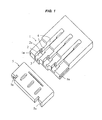
Fig. 1 is a perspective view illustrating an exemplary embodiment of a stopper housing case according to the present invention. -
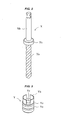
Fig. 2 is a perspective explanatory view illustrating an example of a drill having a flange part, which is projected from a shank part, to bore a dental implant fixture embedding hole at a jawbone when performing a dental implant treatment. -
Fig. 3 is a perspective view illustrating an example of a stopper for defining a drill blade entering depth, where the stopper is fitted on the drill illustrated inFig. 2 from the blade edge side of a blade part, and has a spring-like locking part to be locked with the flange part projected from the shank part of the drill. -
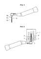
Fig. 4 is a perspective view illustrating a state that the drill illustrated inFig. 2 on which the stopper illustrated inFig. 3 is mounted is attached to a dental handpiece. -
Fig. 5 is a perspective view illustrating a state that the dental handpiece illustrated inFig. 4 to which the drill mounted with the stopper is attached is positioned at a predetermined position of a stopper housing case according to the present invention. - In the drawings, a drill X includes a blade part Xa for boring a dental implant fixture embedding hole at a jawbone when performing a dental implant treatment. A flange part Xc is projected from a shank part Xb.
- A stopper Y for defining a drill blade entering depth has a cylindrical shape having a through hole Ya into which the drill X is inserted from the blade edge side of the blade part Xa. The stopper Y has a spring-like locking part Yb to be locked with the flange part Xc projected from the shank part Xb. When the spring-like locking part Xb is locked with the flange part Xc of the drill X, the spring-like locking part Yb needs to expand once and then return to an original state by its spring action. Thus, a few slits are provided in parallel with the through hole Ya. Furthermore, it is preferable that concave grooves Yc are peripherally provided for every predetermined length on an outer periphery of the cylindrical part following the spring-like locking part Yb.
- A stopper housing case 1 according to the present invention is formed with a hardmaterial such as a metal, hard plastic, or the like. In the stopper housing case 1,
concave parts 2 capable of respectively housing the stoppers Y are provided in parallel. Theconcave part 2 includes a flangepart insertion path 3 formed at one side. The flangepart insertion path 3 has a size preventing the spring-like locking part Yb of the stopper Y from falling out, and capable of inserting the flange part Xc projected from the shank part Xb of the drill X. Further, theconcave part 2 includes a drill bladepart insertion path 4 formed at another side opposite to the one side. The drill bladepart insertion path 4 is capable of inserting the blade part Xa of the drill X. - A
cap 5 is preferably provided on the stopper housing case 1 according to the present invention. Thecap 5 functions for preventing the stoppers Y housed in theconcave parts 2 from falling out of theconcave parts 2 by slide-engaging ofguide parts 5a with slide guide parts 1a. The slide guide parts 1a are provided on both side faces in parallel with the drill bladepart insertion path 4 of the stopper housing case 1. Theguide parts 5a are provided on side parts of an inner face of the cap along the slide guide parts 1a. - In the configuration mentioned above, when end parts at the drill blade
part insertion path 4 side of theconcave parts 2 are provided so as to align together, the flangepart insertion path 3 side of the stopper housing case 1 comes to be in a proj ecting state corresponding to the lengths of the stoppers Y. Since the stopper Y can be thus selected easily, it is preferable. Whenprojection 2a to be engaged with a concave groove Yc formed on an outer peripheral face of the stopper Y are provided on an inner face of the flange part insertion path of theconcave part 2, the stoppers Y can be housed stably in the stopper housing case 1. In addition, at a time of attaching and detaching the stopper Y, the projections are engaged with concave groove Yc formed on the outer peripheral face of the stopper Y, and the stopper Y is not loosened, so it is preferable. When the stopper housing case 1 further includes slide guide parts 1a and thecap 5, the stoppers Y can be stably housed in the stopper housing case 1 without falling out of the stopper housing case 1 at a time of not using the stoppers Y, so that it is preferable. The slide guide parts 1a are provided on both side faces in parallel with the drill bladepart insertion path 4 in the stopper housing case 1 . Theguide parts 5a provided in thecap 5 along the slide guide parts 1a slide-engage with the slide guide part 1a. With this configuration, thecap 5 can prevent the stoppers Y housed in theconcave parts 2 from falling out of theconcave part 2. - When the stopper Y is mounted on the drill X attached to a dental handpiece by using the stopper housing case 1 according to the present invention, the drill X attached to the dental handpiece is moved toward the stopper Y, which is housed in the
concave part 2 so as to position the spring-like locking part Yb at the flangepart insertion path 3 side. The blade part Xa of the drill X is inserted into the through hole Ya penetrating the stopper Y so as to pass through, and a top end of the blade part Xa of the drill X is positioned in the drill bladepart insertion path 4. While keeping this state, the flange part Xc projected from the shank part Xb of the drill X is made to pass through the flangepart insertion path 3, and pushed into and locked with the spring-like locking part Yb of the stopper Y. Then, the drill X is pulled out upward from theconcave part 2, the drill bladepart insertion path 4, and the flangepart insertion path 3. - On the other hand, when the stopper Y is taken out from the drill X attached to the dental handpiece by using the stopper housing case 1 according to the present invention, the drill X is inserted from upside so as to respectively position the blade part Xa of the drill X in the drill
blade insertion path 4, the spring-like locking part Yb of the stopper Y in theconcave part 2 so as to position it at the flangepart insertion path 3 side, and the shank part Xb of the drill X in the flangepart insertion path 3. Then, the dental handpiece is moved in the direction of separating from the flangepart insertion path 3. At this time, the spring-like locking part Yb of the stopper Y cannot move because the spring-like locking part Yb of the stopper Y contacts to the opposite side to the drill bladepart insertion path 4 of the flangepart insertion path 3. Thus, the flange part Xc projected from the shank part Xb of the drill X comes out from the inside of the spring-like locking part Yb of the stopper Y, and passes through the flangepart insertion path 3. Thus, only the stopper Y remains in theconcave part 2, so that the stopper Y can be taken out of the drill X attached to the dental handpiece. - Furthermore, when the stoppers Y are not used, the stoppers Y are housed in the
concave part 2 in the stopper housing case 1 according to the present invention so as to position the spring-like locking parts Yb at the flangepart insertion path 3 side. However, when the stopper housing case 1 further includes slide guide parts 1a and acap 5, the stoppers Y can be stably housed in the stopper housing case 1 without falling out of the stopper housing case 1 at a time of not using the stoppers Y, so that it is preferable. The slide guide parts 1a are provided on both side faces in parallel with the drill bladepart insertion paths 4 in the stopper housing case 1. Theguide parts 5a provided on both side parts of an inner face of thecap 5 along the slide guide parts 1a to slide-engage with the slide guide parts 1a. With this configuration, thecap 5 can prevent the stoppers Y housed in theconcave parts 2 from falling out of theconcave parts 2.
Claims (4)
- A stopper housing case (1) formed with a hard material to house a plurality of stoppers (Y) for defining a drill blade entering depth,
wherein the stopper (Y) has a cylindrical shape to be fitted on a drill (X) from the blade edge side of a blade part (Xa) , and the drill (X) is to bore a dental implant fixture embedding hole at a jawbone when performing a dental implant treatment,
wherein the stopper (Y) comprises a spring-like locking part (Yb) to be locked with a flange part (Xc) projected from a shank part (Xb) of the drill (X),
wherein concave parts (2) capable of respectively housing the stopper (Y) are provided in parallel, wherein each of the concave parts (2) includes, at one side, a flange part insertion path (3) having a size preventing the spring-like locking part (Yb) of the stopper (Y) from falling out and capable of inserting the flange part (Xc) projected from the shank part (Xb) of the drill (X), and
wherein each of the concave parts (2) includes, at another side opposite to the one side, a drill blade part insertion path (4) capable of inserting the blade part (Xa) of the drill (X) . - The stopper housing case (1) as claimed in claim 1, wherein end parts at the drill blade part insertion path (4) side of the concave parts (2) are provided so as to align together.
- The stopper housing case (1) as claimed in claim 1 or 2, wherein projections (2a) to be engaged with a concave groove (Yc) formed on an outer peripheral face of the stopper (Y) are provided on an inner face of the concave part (2).
- The stopper housing case (1) as claimed in any one of claims 1 to 3, wherein the case (1) further comprises a slide guide parts (1a) and a cap (5) , the slide guide parts (1a) are provided on both side faces in parallel with the drill blade part insertion paths (4) in the stopper housing case (1), and the cap (5) including guide parts (5a) provided on side parts of an inner face along the slide guide parts (1a) to slide-engage with the slide guide parts (1a) , so that the cap (5) prevents the stoppers (Y) housed in the concave parts (2) from falling out of the concave part (2).
Applications Claiming Priority (1)
| Application Number | Priority Date | Filing Date | Title |
|---|---|---|---|
| JP2010173593A JP2012029977A (en) | 2010-08-02 | 2010-08-02 | Stopper housing case |
Publications (1)
| Publication Number | Publication Date |
|---|---|
| EP2415419A1 true EP2415419A1 (en) | 2012-02-08 |
Family
ID=44645433
Family Applications (1)
| Application Number | Title | Priority Date | Filing Date |
|---|---|---|---|
| EP11006236A Withdrawn EP2415419A1 (en) | 2010-08-02 | 2011-07-28 | Stopper housing case |
Country Status (4)
| Country | Link |
|---|---|
| US (1) | US8684177B2 (en) |
| EP (1) | EP2415419A1 (en) |
| JP (1) | JP2012029977A (en) |
| KR (1) | KR20120012768A (en) |
Cited By (1)
| Publication number | Priority date | Publication date | Assignee | Title |
|---|---|---|---|---|
| EP2572671A1 (en) * | 2011-09-26 | 2013-03-27 | GC Corporation | Stopper ring for a bone drill |
Families Citing this family (8)
| Publication number | Priority date | Publication date | Assignee | Title |
|---|---|---|---|---|
| DK3299463T3 (en) | 2002-10-30 | 2020-12-07 | Nuevolution As | ENZYMATIC CODING |
| DE102015102658A1 (en) * | 2015-02-25 | 2016-08-25 | B. Braun Avitum Ag | Housing front integrated blood pump |
| US11478320B2 (en) * | 2015-08-06 | 2022-10-25 | Jacobs Emerging Technologies, Llc | Medical device holder |
| USD838240S1 (en) | 2017-01-05 | 2019-01-15 | Advanced Wireless Innovations, Llc | Portable power supply |
| KR101964966B1 (en) * | 2017-07-25 | 2019-04-02 | 이지원 | Parts case for dental crown removing |
| US10478262B2 (en) * | 2017-12-04 | 2019-11-19 | Depuy Ireland Unlimited Company | Orthopaedic instrument system including an instrument caddy and method for assembling a surgical instrument |
| CN114246694A (en) * | 2020-09-25 | 2022-03-29 | 湖南芽正美科技有限公司 | Special appliance convenient to operate for tooth removal |
| US11953318B1 (en) * | 2023-02-24 | 2024-04-09 | King Saud University | Endodontic file measuring device |
Citations (7)
| Publication number | Priority date | Publication date | Assignee | Title |
|---|---|---|---|---|
| US5788488A (en) * | 1996-09-23 | 1998-08-04 | Precision Dental International, Inc. | Dental reamer stop dispenser |
| DE29720294U1 (en) * | 1997-11-10 | 1998-12-10 | Nowak, Marcus, Dr., 14195 Berlin | Device for forming depth marks on implant bed drills |
| US6358049B1 (en) * | 2000-02-08 | 2002-03-19 | Leon A. Cerniway | Endodontic tool length gauge |
| US6405864B1 (en) * | 1998-08-14 | 2002-06-18 | Black & Decker Inc. | Tool container |
| JP2003501135A (en) | 1999-06-03 | 2003-01-14 | アルスリン エス アー | Safety device with stopper for drilling instrument used in oral surgery and device for pre-calibrating and storing drilling depth |
| FR2880534A1 (en) * | 2005-01-11 | 2006-07-14 | Micro Mega Int Mfg Sa | Stop device for e.g. endodontics contra-angle handpiece, has shell with inner cavity of shape similar to handpiece head, and extension terminated by ring having stop function, where extension`s length determines length of work of instrument |
| US20060188840A1 (en) * | 2005-02-24 | 2006-08-24 | Verban Emil M Jr | Dental drill system and stop collar for preparing implant bed for implants |
Family Cites Families (11)
| Publication number | Priority date | Publication date | Assignee | Title |
|---|---|---|---|---|
| US2568089A (en) * | 1947-02-14 | 1951-09-18 | Walter A Pendleton | Holder for drills or the like |
| US4413731A (en) * | 1982-07-07 | 1983-11-08 | Tulon, Inc. | Packaging arrangement for cutting tools such as drills |
| US4619364A (en) * | 1982-09-13 | 1986-10-28 | The Stanley Works | Display package for drill bits and the like |
| FR2605512B3 (en) * | 1986-06-12 | 1988-12-02 | Micro Mega Sa | PACKAGING PACKAGING FOR DENTAL CHANNEL INSTRUMENTS |
| US4811843A (en) * | 1988-02-16 | 1989-03-14 | Precision Carbide Tool Co., Inc. | Protective deployment apparatus for rotary cutting tools |
| US5150788A (en) * | 1991-04-01 | 1992-09-29 | Bernard Weissman | Reamer/wrench/post kit |
| US5692609A (en) * | 1996-12-03 | 1997-12-02 | Lin; Jyh-Sheng | Store box for dental equipment |
| DE19730696B4 (en) * | 1997-07-17 | 2011-06-01 | Rösler, Peter | Device for receiving elongated objects |
| US7165674B2 (en) * | 2004-02-18 | 2007-01-23 | Black & Decker Inc. | Storage container |
| US7066329B2 (en) * | 2003-07-21 | 2006-06-27 | Riley Medical, Inc. | Medical instrument holding and presentation system |
| ES2303978T3 (en) * | 2005-09-05 | 2008-09-01 | Straumann Holding Ag | DENTAL DRILLING DEVICE WITH A BUMPER ELEMENT. |
-
2010
- 2010-08-02 JP JP2010173593A patent/JP2012029977A/en active Pending
-
2011
- 2011-07-28 EP EP11006236A patent/EP2415419A1/en not_active Withdrawn
- 2011-08-01 US US13/195,432 patent/US8684177B2/en not_active Expired - Fee Related
- 2011-08-02 KR KR1020110076889A patent/KR20120012768A/en not_active Ceased
Patent Citations (7)
| Publication number | Priority date | Publication date | Assignee | Title |
|---|---|---|---|---|
| US5788488A (en) * | 1996-09-23 | 1998-08-04 | Precision Dental International, Inc. | Dental reamer stop dispenser |
| DE29720294U1 (en) * | 1997-11-10 | 1998-12-10 | Nowak, Marcus, Dr., 14195 Berlin | Device for forming depth marks on implant bed drills |
| US6405864B1 (en) * | 1998-08-14 | 2002-06-18 | Black & Decker Inc. | Tool container |
| JP2003501135A (en) | 1999-06-03 | 2003-01-14 | アルスリン エス アー | Safety device with stopper for drilling instrument used in oral surgery and device for pre-calibrating and storing drilling depth |
| US6358049B1 (en) * | 2000-02-08 | 2002-03-19 | Leon A. Cerniway | Endodontic tool length gauge |
| FR2880534A1 (en) * | 2005-01-11 | 2006-07-14 | Micro Mega Int Mfg Sa | Stop device for e.g. endodontics contra-angle handpiece, has shell with inner cavity of shape similar to handpiece head, and extension terminated by ring having stop function, where extension`s length determines length of work of instrument |
| US20060188840A1 (en) * | 2005-02-24 | 2006-08-24 | Verban Emil M Jr | Dental drill system and stop collar for preparing implant bed for implants |
Cited By (1)
| Publication number | Priority date | Publication date | Assignee | Title |
|---|---|---|---|---|
| EP2572671A1 (en) * | 2011-09-26 | 2013-03-27 | GC Corporation | Stopper ring for a bone drill |
Also Published As
| Publication number | Publication date |
|---|---|
| US20120028212A1 (en) | 2012-02-02 |
| JP2012029977A (en) | 2012-02-16 |
| US8684177B2 (en) | 2014-04-01 |
| KR20120012768A (en) | 2012-02-10 |
Similar Documents
| Publication | Publication Date | Title |
|---|---|---|
| US8684177B2 (en) | Stopper housing case | |
| EP3421004B1 (en) | Detachable dental implant-coupling prosthesis | |
| EP2377489A1 (en) | Housing container for implant fixture | |
| ES2905117T3 (en) | dental implant replica | |
| US8057229B2 (en) | Dental implant, abutment structure and method for implanting a dental implant | |
| CN104546163B (en) | Including dental implant and the dental prosthesis component through fixed dental prosthesis | |
| EP2572671A1 (en) | Stopper ring for a bone drill | |
| US9700389B2 (en) | Abutment, fixture, dental implant set, dental tap, dental guide, dental tap set and dental drill | |
| CN207084863U (en) | Drilling machine for dental implant and the drilling machine device for dental implanting therewith | |
| KR101419832B1 (en) | Material holder for implant and manufacturing apparatus having the same | |
| JP2011528927A (en) | Dental implant embedding method and system | |
| HK1225264B (en) | Denture fixing attachment | |
| TW201511739A (en) | Implant driver, implant | |
| KR20180136718A (en) | Healing abutment | |
| KR102470652B1 (en) | Implant impression coping with improved connecting structure | |
| KR102250959B1 (en) | Customized abutment for fixing crown | |
| KR20170026911A (en) | Drilling driver for placing dental implant | |
| KR200493997Y1 (en) | Surgical connector for dental fixture | |
| EP2433587A2 (en) | Case for storing stoppers for dental drill bits | |
| KR102068684B1 (en) | Fixture driver for dental surgery | |
| EP2436337B1 (en) | Dental implants | |
| JP4818598B2 (en) | Screw-type implant fixture | |
| KR101486702B1 (en) | Apparatus for procedure of dental implant | |
| KR101535255B1 (en) | Implant fixture removal device | |
| KR20230029744A (en) | connector for implant |
Legal Events
| Date | Code | Title | Description |
|---|---|---|---|
| AK | Designated contracting states |
Kind code of ref document: A1 Designated state(s): AL AT BE BG CH CY CZ DE DK EE ES FI FR GB GR HR HU IE IS IT LI LT LU LV MC MK MT NL NO PL PT RO RS SE SI SK SM TR |
|
| AX | Request for extension of the european patent |
Extension state: BA ME |
|
| PUAI | Public reference made under article 153(3) epc to a published international application that has entered the european phase |
Free format text: ORIGINAL CODE: 0009012 |
|
| 17P | Request for examination filed |
Effective date: 20120419 |
|
| STAA | Information on the status of an ep patent application or granted ep patent |
Free format text: STATUS: THE APPLICATION HAS BEEN WITHDRAWN |
|
| 18W | Application withdrawn |
Effective date: 20140527 |