EP2414235B1 - Deployment apparatuses - Google Patents
Deployment apparatuses Download PDFInfo
- Publication number
- EP2414235B1 EP2414235B1 EP10722846.2A EP10722846A EP2414235B1 EP 2414235 B1 EP2414235 B1 EP 2414235B1 EP 10722846 A EP10722846 A EP 10722846A EP 2414235 B1 EP2414235 B1 EP 2414235B1
- Authority
- EP
- European Patent Office
- Prior art keywords
- deployment
- arm
- coupled
- link
- angle
- Prior art date
- Legal status (The legal status is an assumption and is not a legal conclusion. Google has not performed a legal analysis and makes no representation as to the accuracy of the status listed.)
- Active
Links
Images



Classifications
-
- B—PERFORMING OPERATIONS; TRANSPORTING
- B64—AIRCRAFT; AVIATION; COSMONAUTICS
- B64D—EQUIPMENT FOR FITTING IN OR TO AIRCRAFT; FLIGHT SUITS; PARACHUTES; ARRANGEMENT OR MOUNTING OF POWER PLANTS OR PROPULSION TRANSMISSIONS IN AIRCRAFT
- B64D11/00—Passenger or crew accommodation; Flight-deck installations not otherwise provided for
- B64D11/0015—Arrangements for entertainment or communications, e.g. radio, television
- B64D11/00153—Monitors mounted on or in the seat other than the seat back
-
- B—PERFORMING OPERATIONS; TRANSPORTING
- B64—AIRCRAFT; AVIATION; COSMONAUTICS
- B64D—EQUIPMENT FOR FITTING IN OR TO AIRCRAFT; FLIGHT SUITS; PARACHUTES; ARRANGEMENT OR MOUNTING OF POWER PLANTS OR PROPULSION TRANSMISSIONS IN AIRCRAFT
- B64D11/00—Passenger or crew accommodation; Flight-deck installations not otherwise provided for
- B64D11/0015—Arrangements for entertainment or communications, e.g. radio, television
-
- B—PERFORMING OPERATIONS; TRANSPORTING
- B60—VEHICLES IN GENERAL
- B60N—SEATS SPECIALLY ADAPTED FOR VEHICLES; VEHICLE PASSENGER ACCOMMODATION NOT OTHERWISE PROVIDED FOR
- B60N3/00—Arrangements or adaptations of other passenger fittings, not otherwise provided for
- B60N3/001—Arrangements or adaptations of other passenger fittings, not otherwise provided for of tables or trays
-
- B—PERFORMING OPERATIONS; TRANSPORTING
- B64—AIRCRAFT; AVIATION; COSMONAUTICS
- B64D—EQUIPMENT FOR FITTING IN OR TO AIRCRAFT; FLIGHT SUITS; PARACHUTES; ARRANGEMENT OR MOUNTING OF POWER PLANTS OR PROPULSION TRANSMISSIONS IN AIRCRAFT
- B64D11/00—Passenger or crew accommodation; Flight-deck installations not otherwise provided for
- B64D11/06—Arrangements of seats, or adaptations or details specially adapted for aircraft seats
- B64D11/0638—Arrangements of seats, or adaptations or details specially adapted for aircraft seats with foldable tables, trays or cup holders
Definitions
- the field of the invention relates to deployment apparatuses for passenger seats or the like.
- a deployment apparatus and a method of deploying a deployment apparatus in accordance with the present invention are set forth in the appended claims.
- Embodiments of the present invention include a deployment apparatus comprising a deployment object, a deployment arm, a deployment link, a pivot housing, at least two linear guides, and a gas spring.
- Deployment objects may include but are not limited to a display monitor, a tray table, and a cocktail table.
- the deployment object may be coupled to the deployment arm via a deployment connector that is pivotally coupled to the deployment object and rotationally coupled to an end of the deployment arm.
- the deployment link includes a mating surface that confronts a mating surface of the deployment arm and an opposing end that is coupled in a fixed location to a deployment arm mount.
- the pivot housing is adjacent the mating surfaces of the deployment link and the deployment arm.
- the at least two linear guides are coupled to the deployment arm mount and comprise at least two tracks that are slidingly engaged with a plurality of linear bearings on the surface of the pivot housing.
- the gas spring is coupled at one end to the pivot housing and coupled at an opposing end to the deployment arm mount.
- the deployment apparatus includes a locking arm that releasably engages a latch pin that is positioned on the deployment arm.
- Other embodiments of the deployment apparatus may include a spring coupled to an end of the locking arm and a projection on the pivot housing.
- a rotation limitation pin is coupled to the mating surface of the deployment arm and contacts the deployment link when the deployment arm is positioned between a stowed angle and a released angle.
- the deployment apparatus may be deployed by releasing the latch pin from the locking arm.
- the gas spring is then released, which raises the pivot housing to an upper end of the at least two linear guides.
- the deployment arm rotates from a stowed angle to a released angle due to contact between the deployment link and the rotation limiting pin.
- the deployment apparatus may have a released angle of at least 10 degrees and a displaced vertical distance of at least 0.5 inches.
- Embodiments of the invention provide deployment mechanisms for use with a vehicle seat. While the deployment mechanisms are discussed for use with aircraft seats, they are by no means so limited. Rather, embodiments of the deployment mechanisms may be used in vehicle seats of any type or otherwise as desired.
- FIGS 1-8 illustrate one embodiment of a deployment apparatus 10.
- the deployment apparatus 10 comprises a deployment object 12, a deployment connector 14, a deployment arm 16, a vertical slide 18, and a deployment arm mount 20.
- the deployment object 12 is a three-dimensional object having a length X, a height Y, and a depth Z, where the X and Y sides define a surface area 13.
- the deployment object 12 may be any object including but not limited to any type of screen that displays visual images corresponding to electrical signals that it receives from an appropriate source, a food tray, a cocktail tray, or other similar objects.
- the deployment object 12 is pivotally coupled to the deployment connector 14.
- the deployment connector 14 has any appropriate shape that allows the deployment object 12 to pivot relative to its coupling to the deployment connector 14.
- the deployment connector 14 includes a rounded seat that is pivotally coupled to at least a portion of the lower length X of the deployment object 12.
- Figures 1 and 2 illustrate one embodiment of the coupling between the deployment connector 14 and the deployment arm 16.
- the deployment connector 14 is coupled to an end 22 of the deployment arm 16 in a manner that allows the deployment connector 14 to rotate relative to the deployment arm 16 along the longitudinal axes of both the deployment connector 14 and the deployment arm 16.
- Both the deployment connector 14 and the deployment arm 16 may be formed of any suitable material including but not limited to aluminum, stainless steel, other metallic material, composite material, or other similar material.
- the deployment arm 16 may have any appropriate cross-sectional shape including but not limited to rectilinear, oval, circular, triangular, or any other similar shape.
- the longitudinal shape of the deployment arm 16 may have a straight, curved, or any other suitable profile.
- an opposing end 24 of the deployment arm 16 includes a pivot 26.
- the deployment arm 16 is pivotally coupled to the vertical slide 18 via the pivot 26, where the pivot 26 is shaped to allow the deployment arm 16 to pivot relative to the vertical slide 18.
- the pivot 26 may have a cylindrical, oval, spherical, or other similar shape that allows the pivot 26 to rotate in a suitable manner.
- Figures 3-8 illustrate one embodiment of the vertical slide 18.
- the vertical slide 18 comprises a deployment link 28, a pivot housing 30, a cable cover 32, a gas spring 34, and at least two linear guides 36.
- a mating surface of the deployment link 28 confronts a mating surface on the pivot 26.
- the pivot 26 is coupled to the deployment link 28 by a fastener 38 that passes through an aperture 40 in the pivot 26 and a co-centrically aligned aperture 42 in one end of the deployment link 28.
- the pivot 26 and the deployment link 28 may be coupled by any appropriate manner that allows the pivot 26 and the deployment link 28 to rotate relative to one another.
- the pivot housing 30 is positioned adjacent one side of the coupled pivot 26 and the deployment link 28, and the cable cover 32 is positioned adjacent the opposing side of the pivot 26 and the deployment link 28.
- the pivot housing 30 and the cable cover 32 are coupled to one another to form an enclosure 44 surrounding the junction between the pivot 26 and the deployment link 28.
- the pivot housing 30 and the cable cover 32 may be formed of any suitable material including but not limited to aluminum, stainless steel, other metallic material, composite material, or other similar material.
- the pivot 26 also includes a rotation limiting pin 46.
- the rotation limiting pin 46 is located on the mating surface of the pivot 26 that confronts the deployment link 28. When the deployment arm 16 is placed in certain orientations relative to the deployment link, the rotation limiting pin 46 is rotated into a position where the rotation limiting pin 46 contacts the deployment link 28.
- the rotation limiting pin 46 contacts the deployment link 28 over a range of angles from a stowed angle to a released angle.
- the stowed angle position may be defined as any appropriate angle formed between the deployment arm 16 and a vertical axis. In one embodiment, as shown in Figures 4 and 8 , the stowed angle position is an angle of approximately 0 degrees between the deployment arm 16 and the vertical axis. However, one of skill in the relevant art will understand that any appropriate angle may be used that results in a stowed position of the deployment apparatus 10.
- the released angle may range from 10 degrees to 60 degrees from the stowed angle position, and may preferably be approximately 30 degrees from the stowed angle position.
- the deployment link 28 prevents further travel of the deployment arm 16 along its rotational arc in that direction.
- an external rear surface 48 of the pivot housing 30 include a plurality of linear bearings 50.
- the linear bearings 50 provide a sliding surface between the pivot housing 30 and the at least two linear guides 36.
- the linear bearings 50 include but are not limited to inserted bearings or bushings.
- the at least two linear guides 36 are in turn coupled to the deployment arm mount 20.
- the linear guides 36 are integrated into the deployment arm mount 20.
- the linear bearings 50 and the linear guides 36 may be formed of any suitable material that does not impede the ability of the pivot housing 30 to travel along the at least two linear guides 36.
- the linear bearing 50 materials include but are not limited to nylon, delrin, Teflon, or other similar coating materials.
- the linear guide 36 materials include but are not limited to aluminum, to stainless steel, other metallic material, composite material, or other similar material.
- the deployment arm mount 20 may be formed of any suitable material including but not limited to aluminum, stainless steel, other metallic material, composite material, or other similar material.
- the deployment arm mount 20 and the at least two linear guides 36 have a length that accommodates the vertical travel distance required by the pivot housing 30 to achieve the desired reduction in swing trajectory of the deployment object 12.
- the pivot housing 30 also includes a projection 52.
- An upper end 54 of the gas spring 34 is coupled to the projection 52 and the lower end 56 of the gas spring 34 is coupled to a projection 58 extending from the deployment arm mount 20.
- the gas spring 34 is coupled to a link, which in turn is coupled to the pivot housing 30.
- the gas spring 34 may be coupled to the pivot housing 30 and the deployment arm mount 20 in any suitable manner including but not limited to pins, screws, or other types of mechanical fasteners.
- the pivot housing 30 includes a locking arm 60.
- the locking arm 60 includes a hook 62 that is configured to engage a latch pin 61 on the deployment arm 16.
- the locking arm 60 is also coupled at its opposing end to one end of a spring 64.
- the spring 64 is coupled at its opposing end to a projection 66 extending from the pivot housing 30.
- the locking arm 60 releases the latch pin 61 when a passenger pulls a lever or pushes a button that lifts the locking arm 60 that is attached to the spring 64.
- any suitable releasable mechanical fasteners may be used to releasably engage the latch pin 61.
- Figures 4-5 and 7-8 illustrate one embodiment in which an opposing end 68 of the deployment link 28 is pivotally coupled to a projection 70 extending from the deployment arm mount 20.
- the end 68 creates a fixed point about which the deployment link 28 pivots.
- the opposing end 68 may be coupled to any appropriate structure that restricts the movement of the opposing end 68.
- one embodiment of the deployment apparatus 10 includes the vertical slide 18 to deploy the deployment arm 16 in an upward direction while the deployment arm 16 also rotates outward along its rotational arc.
- the pivot housing 30 is located at the lower end of the at least two linear guides 36, the latch pin 61 is engaged by the locking arm 60, the deployment arm 16 is oriented in the stowed angle position, and the deployment object 12 is oriented so that the plane of the surface area 13 is substantially parallel with the plane of travel of the deployment arm 16.
- a passenger releases the locking arm 60 to deploy the deployment object 12 from its stowed angle position.
- Releasing the locking arm 60 disengages the latch pin 61.
- This disengagement releases the gas spring 34, which causes the pivot housing 30 to travel to the upper end of the at least two linear guides 36.
- the upward movement of the pivot housing 30 simultaneously causes the deployment link 28 to press against the rotation limiting pin 46, which in turn causes the deployment arm 16 to rotate outwardly from its stowed angle position.
- the simultaneous upward and outward movement of the deployment arm 16 places the deployment arm 16 into the released angle position, which is illustrated in Figure 5 .
- the slide and link mechanism creates a displaced vertical distance that may be used to create passenger seats with a lower seat cross beam or to accommodate a larger deployment object within an existing storage location.
- Figure 6 illustrates that the displaced vertical distance is calculated by measuring the difference between the lowest point on a hypothetical rotational arc created by the deployment object relative to the actual lowest point along the rotational arc created by the deployment object.
- the displaced vertical distance is at least 0.5 inches and may range up to 3 inches, and may preferably be approximately 1.5 inches.
- a passenger may then manually pull the deployment arm 16 into a desired deployment angle, where the deployment angle may range from the released angle to 150 degrees, with the released angle setting controlled by the vertical slide 18. As illustrated in Figure 7 , the passenger then rotates the deployment object 12 into a deployed position for viewing.
- the passenger When the passenger is ready to stow the deployment object 12, the passenger rotates the deployment object 12 back to its stowed orientation. In a stowed orientation, the plane of the surface area 13 is substantially parallel with the plane of travel of the deployment arm 16. The passenger then manually rotates the deployment arm 16 back to the stowed angle position, which causes the deployment arm 16 to simultaneously travel downward and inward while compressing the gas spring 34. The downward pressure exerted by the passenger causes the latch pin 61 to slide over the hook 62 where the latch pin 61 is then engaged by the locking arm 60.
Landscapes
- Engineering & Computer Science (AREA)
- Aviation & Aerospace Engineering (AREA)
- Transportation (AREA)
- Mechanical Engineering (AREA)
- Vehicle Step Arrangements And Article Storage (AREA)
- Superstructure Of Vehicle (AREA)
Description
- The field of the invention relates to deployment apparatuses for passenger seats or the like.
- Many vehicle seats such as those on passenger aircraft, buses, trains and the like require stowage of objects when not in use. For example, many seat designs utilize the space below the seat cross beams to stow video devices, tray tables, cocktail tables, and the like. In many instances, the swing trajectory of these objects requires additional storage length or the size of the object must be limited to properly stow within the existing storage available.
- In certain situations, however, it may be desirable to reduce the size of the storage compartment or to increase the size of the deployment object. In these circumstances, there exists a need to limit the swing trajectory arc required to stow these objects.
- Document
US 5 732 919 A (ROSEN JOHN B [US] ET AL) 31 March 1998 discloses a deployment apparatus for a stowable vehicle monitor (Abstract,Fig. 1 ) comprising a gas spring (32) and a locking mechanism (Fig. 5A and 5B ) which is to be activated when raising the deployment apparatus housing. However, this document does not disclose a deployment apparatus with a deployment link. - In
document DE 20 2007 015886 U1 (HESSE DETLEF [DE]) 17 January 2008 a teaching is included, that a locking mechanism with a gas spring or a locking hinge is to be used ([0021]) for deployment, but there is no indication to use them in combination. - A deployment apparatus and a method of deploying a deployment apparatus in accordance with the present invention are set forth in the appended claims.
- Embodiments of the present invention include a deployment apparatus comprising a deployment object, a deployment arm, a deployment link, a pivot housing, at least two linear guides, and a gas spring. Deployment objects may include but are not limited to a display monitor, a tray table, and a cocktail table. The deployment object may be coupled to the deployment arm via a deployment connector that is pivotally coupled to the deployment object and rotationally coupled to an end of the deployment arm. The deployment link includes a mating surface that confronts a mating surface of the deployment arm and an opposing end that is coupled in a fixed location to a deployment arm mount. The pivot housing is adjacent the mating surfaces of the deployment link and the deployment arm. The at least two linear guides are coupled to the deployment arm mount and comprise at least two tracks that are slidingly engaged with a plurality of linear bearings on the surface of the pivot housing. Finally, the gas spring is coupled at one end to the pivot housing and coupled at an opposing end to the deployment arm mount.
- In some embodiments, the deployment apparatus includes a locking arm that releasably engages a latch pin that is positioned on the deployment arm. Other embodiments of the deployment apparatus may include a spring coupled to an end of the locking arm and a projection on the pivot housing. In yet other embodiments, a rotation limitation pin is coupled to the mating surface of the deployment arm and contacts the deployment link when the deployment arm is positioned between a stowed angle and a released angle.
- The deployment apparatus may be deployed by releasing the latch pin from the locking arm. The gas spring is then released, which raises the pivot housing to an upper end of the at least two linear guides. In some embodiments, the deployment arm rotates from a stowed angle to a released angle due to contact between the deployment link and the rotation limiting pin. The deployment apparatus may have a released angle of at least 10 degrees and a displaced vertical distance of at least 0.5 inches.
-
-
Figure 1 is an exploded perspective view of a deployment apparatus according to one embodiment of the present invention. -
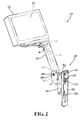
Figure 2 is an assembled perspective view of the deployment apparatus ofFigure 1 . -
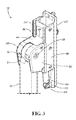
Figure 3 is a perspective view of the vertical slide mechanism of the deployment apparatus ofFigure 1 . -
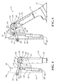
Figure 4 is a side view of the deployment apparatus ofFigure 1 in a stowed position. -
Figure 5 is a side view of the deployment apparatus ofFigure 1 in a released position. -
Figure 6 is a side view showing the change in the swing trajectory of the deployment object created by the deployment apparatus ofFigure 1 . -
Figure 7 is a side view of the deployment apparatus ofFigure 1 in a deployed position. -
Figure 8 is another side view of the deployment apparatus ofFigure 1 in a stowed position. - Embodiments of the invention provide deployment mechanisms for use with a vehicle seat. While the deployment mechanisms are discussed for use with aircraft seats, they are by no means so limited. Rather, embodiments of the deployment mechanisms may be used in vehicle seats of any type or otherwise as desired.
-
Figures 1-8 illustrate one embodiment of adeployment apparatus 10. In this embodiment, thedeployment apparatus 10 comprises adeployment object 12, adeployment connector 14, adeployment arm 16, avertical slide 18, and adeployment arm mount 20. - In some embodiments, as shown in
Figures 1 and2 , thedeployment object 12 is a three-dimensional object having a length X, a height Y, and a depth Z, where the X and Y sides define asurface area 13. Thedeployment object 12 may be any object including but not limited to any type of screen that displays visual images corresponding to electrical signals that it receives from an appropriate source, a food tray, a cocktail tray, or other similar objects. - The
deployment object 12 is pivotally coupled to thedeployment connector 14. Thedeployment connector 14 has any appropriate shape that allows thedeployment object 12 to pivot relative to its coupling to thedeployment connector 14. In one embodiment, as shown inFigures 1-2 , thedeployment connector 14 includes a rounded seat that is pivotally coupled to at least a portion of the lower length X of thedeployment object 12. -
Figures 1 and2 illustrate one embodiment of the coupling between thedeployment connector 14 and thedeployment arm 16. In this embodiment, thedeployment connector 14 is coupled to anend 22 of thedeployment arm 16 in a manner that allows thedeployment connector 14 to rotate relative to thedeployment arm 16 along the longitudinal axes of both thedeployment connector 14 and thedeployment arm 16. Both thedeployment connector 14 and thedeployment arm 16 may be formed of any suitable material including but not limited to aluminum, stainless steel, other metallic material, composite material, or other similar material. Thedeployment arm 16 may have any appropriate cross-sectional shape including but not limited to rectilinear, oval, circular, triangular, or any other similar shape. The longitudinal shape of thedeployment arm 16 may have a straight, curved, or any other suitable profile. - In some embodiments, an
opposing end 24 of thedeployment arm 16 includes apivot 26. Thedeployment arm 16 is pivotally coupled to thevertical slide 18 via thepivot 26, where thepivot 26 is shaped to allow thedeployment arm 16 to pivot relative to thevertical slide 18. Thepivot 26 may have a cylindrical, oval, spherical, or other similar shape that allows thepivot 26 to rotate in a suitable manner. -
Figures 3-8 illustrate one embodiment of thevertical slide 18. In this embodiment, thevertical slide 18 comprises adeployment link 28, apivot housing 30, acable cover 32, agas spring 34, and at least twolinear guides 36. In some embodiments, a mating surface of thedeployment link 28 confronts a mating surface on thepivot 26. Thepivot 26 is coupled to thedeployment link 28 by afastener 38 that passes through anaperture 40 in thepivot 26 and a co-centrically alignedaperture 42 in one end of thedeployment link 28. However, thepivot 26 and thedeployment link 28 may be coupled by any appropriate manner that allows thepivot 26 and thedeployment link 28 to rotate relative to one another. - In some embodiments, as shown in
Figure 3 , thepivot housing 30 is positioned adjacent one side of the coupledpivot 26 and thedeployment link 28, and thecable cover 32 is positioned adjacent the opposing side of thepivot 26 and thedeployment link 28. The pivot housing 30 and thecable cover 32 are coupled to one another to form anenclosure 44 surrounding the junction between thepivot 26 and thedeployment link 28. Thepivot housing 30 and thecable cover 32 may be formed of any suitable material including but not limited to aluminum, stainless steel, other metallic material, composite material, or other similar material. - In one embodiment shown in
Figures 4-8 , thepivot 26 also includes arotation limiting pin 46. Therotation limiting pin 46 is located on the mating surface of thepivot 26 that confronts thedeployment link 28. When thedeployment arm 16 is placed in certain orientations relative to the deployment link, therotation limiting pin 46 is rotated into a position where therotation limiting pin 46 contacts thedeployment link 28. - The
rotation limiting pin 46 contacts thedeployment link 28 over a range of angles from a stowed angle to a released angle. The stowed angle position may be defined as any appropriate angle formed between thedeployment arm 16 and a vertical axis. In one embodiment, as shown inFigures 4 and8 , the stowed angle position is an angle of approximately 0 degrees between thedeployment arm 16 and the vertical axis. However, one of skill in the relevant art will understand that any appropriate angle may be used that results in a stowed position of thedeployment apparatus 10. - The released angle may range from 10 degrees to 60 degrees from the stowed angle position, and may preferably be approximately 30 degrees from the stowed angle position. When the
deployment arm 16 is positioned at the stowed angle, thedeployment link 28 prevents further travel of thedeployment arm 16 along its rotational arc in that direction. - As shown in
Figure 3 , some embodiments of an externalrear surface 48 of thepivot housing 30 include a plurality oflinear bearings 50. Thelinear bearings 50 provide a sliding surface between thepivot housing 30 and the at least twolinear guides 36. In some embodiments, thelinear bearings 50 include but are not limited to inserted bearings or bushings. The at least twolinear guides 36 are in turn coupled to thedeployment arm mount 20. In some embodiments, thelinear guides 36 are integrated into thedeployment arm mount 20. Thelinear bearings 50 and thelinear guides 36 may be formed of any suitable material that does not impede the ability of thepivot housing 30 to travel along the at least twolinear guides 36. For example, thelinear bearing 50 materials include but are not limited to nylon, delrin, Teflon, or other similar coating materials. Thelinear guide 36 materials include but are not limited to aluminum, to stainless steel, other metallic material, composite material, or other similar material. - The
deployment arm mount 20 may be formed of any suitable material including but not limited to aluminum, stainless steel, other metallic material, composite material, or other similar material. Thedeployment arm mount 20 and the at least twolinear guides 36 have a length that accommodates the vertical travel distance required by thepivot housing 30 to achieve the desired reduction in swing trajectory of thedeployment object 12. - The
pivot housing 30 also includes aprojection 52. Anupper end 54 of thegas spring 34 is coupled to theprojection 52 and thelower end 56 of thegas spring 34 is coupled to aprojection 58 extending from thedeployment arm mount 20. In other embodiments, thegas spring 34 is coupled to a link, which in turn is coupled to thepivot housing 30. One of skill in the relevant art will understand that thegas spring 34 may be coupled to thepivot housing 30 and thedeployment arm mount 20 in any suitable manner including but not limited to pins, screws, or other types of mechanical fasteners. - In some embodiments, as shown in
Figures 7 and8 , thepivot housing 30 includes a lockingarm 60. The lockingarm 60 includes ahook 62 that is configured to engage alatch pin 61 on thedeployment arm 16. The lockingarm 60 is also coupled at its opposing end to one end of aspring 64. Thespring 64 is coupled at its opposing end to a projection 66 extending from thepivot housing 30. The lockingarm 60 releases thelatch pin 61 when a passenger pulls a lever or pushes a button that lifts thelocking arm 60 that is attached to thespring 64. In other embodiments, any suitable releasable mechanical fasteners may be used to releasably engage thelatch pin 61. -
Figures 4-5 and7-8 illustrate one embodiment in which an opposingend 68 of thedeployment link 28 is pivotally coupled to aprojection 70 extending from thedeployment arm mount 20. As a result, theend 68 creates a fixed point about which thedeployment link 28 pivots. In other embodiments, the opposingend 68 may be coupled to any appropriate structure that restricts the movement of the opposingend 68. - As illustrated in
Figure 6 , one embodiment of thedeployment apparatus 10 includes thevertical slide 18 to deploy thedeployment arm 16 in an upward direction while thedeployment arm 16 also rotates outward along its rotational arc. When thedeployment object 12 is in a stowed position, as shown inFigures 4 and8 , thepivot housing 30 is located at the lower end of the at least twolinear guides 36, thelatch pin 61 is engaged by the lockingarm 60, thedeployment arm 16 is oriented in the stowed angle position, and thedeployment object 12 is oriented so that the plane of thesurface area 13 is substantially parallel with the plane of travel of thedeployment arm 16. - In the embodiments illustrated in
Figures 1-8 , a passenger releases the lockingarm 60 to deploy thedeployment object 12 from its stowed angle position. Releasing the lockingarm 60 disengages thelatch pin 61. This disengagement releases thegas spring 34, which causes thepivot housing 30 to travel to the upper end of the at least twolinear guides 36. The upward movement of thepivot housing 30 simultaneously causes thedeployment link 28 to press against therotation limiting pin 46, which in turn causes thedeployment arm 16 to rotate outwardly from its stowed angle position. The simultaneous upward and outward movement of thedeployment arm 16 places thedeployment arm 16 into the released angle position, which is illustrated inFigure 5 . - In some embodiments, as shown in
Figure 6 , the slide and link mechanism creates a displaced vertical distance that may be used to create passenger seats with a lower seat cross beam or to accommodate a larger deployment object within an existing storage location.Figure 6 illustrates that the displaced vertical distance is calculated by measuring the difference between the lowest point on a hypothetical rotational arc created by the deployment object relative to the actual lowest point along the rotational arc created by the deployment object. The displaced vertical distance is at least 0.5 inches and may range up to 3 inches, and may preferably be approximately 1.5 inches. - Once the
deployment arm 16 is in the released angle position, a passenger may then manually pull thedeployment arm 16 into a desired deployment angle, where the deployment angle may range from the released angle to 150 degrees, with the released angle setting controlled by thevertical slide 18. As illustrated inFigure 7 , the passenger then rotates thedeployment object 12 into a deployed position for viewing. - When the passenger is ready to stow the
deployment object 12, the passenger rotates thedeployment object 12 back to its stowed orientation. In a stowed orientation, the plane of thesurface area 13 is substantially parallel with the plane of travel of thedeployment arm 16. The passenger then manually rotates thedeployment arm 16 back to the stowed angle position, which causes thedeployment arm 16 to simultaneously travel downward and inward while compressing thegas spring 34. The downward pressure exerted by the passenger causes thelatch pin 61 to slide over thehook 62 where thelatch pin 61 is then engaged by the lockingarm 60. - The foregoing is provided for purposes of illustrating, explaining, and describing embodiments of the present invention. Further modifications and adaptations to these embodiments will be apparent to those skilled in the art and may be made without departing from the scope of the appended claims.
Claims (14)
- A deployment apparatus comprising:i) a deployment object (12);ii) a deployment arm (16) coupled to the deployment object;iii) a deployment link (28), an end (42) of the deployment link comprising a mating surface that confronts a mating surface of the deployment arm and an opposing end (68) of the deployment link is coupled to a deployment arm mount (20);iv) a pivot housing (30) adjacent the mating surfaces of the deployment link and the deployment arm;v) at least two linear guides (36), coupled to the deployment arm mount and comprising at least two tracks that are slidingly engaged with a plurality of linear bearings (50) on the surface of the pivot housing (30); and;vi) a gas spring (34) coupled at one end to the pivot housing and coupled at an opposing end to the deployment arm mount;
characterized in that:vii) the opposing end (68) of the deployment link (28) is directly coupled in a fixed location (70) to the deployment arm mount (20); - The deployment apparatus of claim 1, wherein the deployment object (12) is a member of the group consisting of a display monitor, a tray table, and a cocktail table.
- The deployment apparatus of claim 1 or claim 2, further comprising a deployment connector (14) pivotally coupled to the deployment object (12) and rotationally coupled to an end (22) of the deployment arm (16).
- The deployment apparatus of any of claims 1 to 3, wherein the at least two linear guides (36) are integrated into the deployment arm mount (20).
- The deployment apparatus of any of claims 1 to 4, further comprising a rotation limiting pin (46) coupled to the mating surface of the deployment arm (16) configured to contact the deployment link (28) when the deployment arm is positioned between a stowed angle and a released wherein:i) the stowed angle is an angle formed between the longitudinal axis of the deployment arm and a vertical axis, andii) the released angle is an angle formed between the deployment arm and the stowed angle.
- The deployment apparatus of claim 5, wherein the:i) stowed angle has a range of 0 to 90 degrees;
and/or,ii) released angle is at least 10 degrees from the stowed angle. - The deployment apparatus of claim 5 or 6, wherein the deployment arm (16) is pivotally coupled to a vertical slide via a pivot (26), said vertical slide comprises the deployment link (28), the pivot housing (30), the gas spring (34), at least two linear guides (36) and a cable cover (32).
- The deployment apparatus of claim 7, wherein the pivot (26) comprises the rotation limiting pin (46) coupled to the mating surface of the deployment arm.
- The deployment apparatus of claim 7 or 8, wherein the vertical slide is configured to deploy the deployment arm in an upward direction such that upward movement of the pivot housing (30) simultaneously causes the deployment link (28) to press against the rotation limiting pin (46), which in turn causes the deployment arm (16) to rotate outwardly from the stowed angle position into the released angle position.
- The deployment apparatus of any of claims 7 to 9, wherein the vertical slide and the deployment link allow the deployment apparatus to be displaceable through a vertical distance so as to permit the deployment object to rotate along a rotational arc having a displaced vertical distance of at least 1.27cm (0.5 inches) or 3.81cm (1.5 inches) measured from the lowest point on a hypothetical rotational arc created by the deployment object relative to an actual lowest point along the rotational arc created by the deployment object.
- A deployment apparatus as claimed in any of the preceding claims, wherein the deployment apparatus (10) has a deployable angle of at least 10 degrees from a vertical axis and/or is displaceable through a vertical distance of at least 1.27 cm (0.5 inches).
- The deployment apparatus of any of claims 1 to 11, further comprising a locking arm (60) configured to releasably engage a latch pin (61) that is positioned on the deployment arm (16).
- The deployment apparatus of claim 12, further comprising a spring (64) coupled to an end of the locking arm (60) and a projection (66) on the pivot housing (30).
- A method of deploying a deployment apparatus of claim 12 or 13 comprising the steps of:i) releasing the latch pin (61) from the locking arm (60);ii) releasing the gas spring (34); andiii) raising the pivot housing (30) to an upper end of the at least two linear guides (36).
Applications Claiming Priority (2)
| Application Number | Priority Date | Filing Date | Title |
|---|---|---|---|
| US16453009P | 2009-03-30 | 2009-03-30 | |
| PCT/US2010/029147 WO2010117758A2 (en) | 2009-03-30 | 2010-03-30 | Deployment apparatuses |
Publications (2)
| Publication Number | Publication Date |
|---|---|
| EP2414235A2 EP2414235A2 (en) | 2012-02-08 |
| EP2414235B1 true EP2414235B1 (en) | 2015-08-26 |
Family
ID=42782901
Family Applications (1)
| Application Number | Title | Priority Date | Filing Date |
|---|---|---|---|
| EP10722846.2A Active EP2414235B1 (en) | 2009-03-30 | 2010-03-30 | Deployment apparatuses |
Country Status (4)
| Country | Link |
|---|---|
| US (2) | US8322670B2 (en) |
| EP (1) | EP2414235B1 (en) |
| CA (1) | CA2756978A1 (en) |
| WO (1) | WO2010117758A2 (en) |
Cited By (1)
| Publication number | Priority date | Publication date | Assignee | Title |
|---|---|---|---|---|
| US10322805B2 (en) | 2013-01-07 | 2019-06-18 | Safran Seats Usa Llc | Video arm deployment method |
Families Citing this family (27)
| Publication number | Priority date | Publication date | Assignee | Title |
|---|---|---|---|---|
| CA2756978A1 (en) | 2009-03-30 | 2010-10-14 | Weber Aircraft Llc | Deployment apparatuses |
| WO2013141869A1 (en) * | 2012-03-22 | 2013-09-26 | Satterfield Johnny A | Video arm assembly |
| DE102012204736A1 (en) * | 2012-03-23 | 2013-09-26 | Lufthansa Technik Ag | Bracket for a control console in an aircraft seat |
| US8931734B2 (en) * | 2012-09-13 | 2015-01-13 | Hamilton Sundstrand Corporation | Ram air turbine release cable assembly |
| US9527456B2 (en) * | 2012-11-05 | 2016-12-27 | Kinetix Ag | Device for retaining flat, approximately rectangular appliances such as tablet computers or mobile telephones in the interior of a motor vehicle |
| US9164537B2 (en) * | 2013-03-15 | 2015-10-20 | Toshiba Global Commerce Solutions Holding Corporation | Display screen assembly having a selectively engageable mount assembly |
| EP3019371B1 (en) * | 2013-07-09 | 2018-08-22 | Zodiac Seats US LLC | Friction stop device |
| USD740243S1 (en) * | 2013-08-07 | 2015-10-06 | Virgin America Inc. | In-flight entertainment system |
| AU2014326732A1 (en) * | 2013-09-26 | 2016-03-24 | Gojo Industries, Inc. | Modular point of care dispenser system |
| WO2015054796A1 (en) * | 2013-10-18 | 2015-04-23 | Ingenio Aerospace | Infrastructure for mobile devices and electronic loose equipment |
| CN103538532B (en) * | 2013-11-06 | 2016-04-13 | 杭州杭正电子科技有限公司 | A kind of vehicle mounted electric turnover telltale |
| DE202014101544U1 (en) * | 2014-04-01 | 2014-05-19 | Zim Flugsitz Gmbh | Holding device for a display and / or operating unit for attachment in an aircraft and display and operating device with a holding device |
| DE102015222952A1 (en) * | 2015-11-20 | 2017-05-24 | Airbus Operations Gmbh | A display device mounting system for mounting in an aircraft passenger cabin and aircraft passenger cabin comprising a display device mounting system |
| US10734773B2 (en) | 2016-04-18 | 2020-08-04 | Ingenio Aerospace Inc. | Infrastructure for mobile devices and electronic loose equipment |
| WO2018022033A1 (en) * | 2016-07-27 | 2018-02-01 | Zodiac Seats Us Llc | Pivoting video arm mechanism and assembly |
| GB2563211B (en) * | 2017-06-05 | 2019-09-04 | Ford Global Tech Llc | A portable electronic device support assembly |
| US11072261B2 (en) * | 2019-01-07 | 2021-07-27 | Adient Engineering and IP GmbH | Tray table device for a seat of a vehicle and vehicle seat |
| US10864991B2 (en) * | 2019-03-20 | 2020-12-15 | B/E Aerospace, Inc. | Adjustable cantilevered table assembly |
| US11904812B2 (en) | 2019-12-12 | 2024-02-20 | Reinhold Industries, Inc. | Passenger vehicle personal electronic device holders |
| US11897615B2 (en) | 2020-03-19 | 2024-02-13 | Reinhold Industries, Inc. | Tablet holder |
| KR102869257B1 (en) * | 2020-10-06 | 2025-10-10 | 현대자동차주식회사 | Device for automatically adjusting angle of monitor mounted on seat back of vehicle |
| JP7123102B2 (en) * | 2020-10-07 | 2022-08-22 | 本田技研工業株式会社 | seat table |
| JP7112465B2 (en) * | 2020-10-07 | 2022-08-03 | 本田技研工業株式会社 | seat table |
| US11660994B2 (en) * | 2021-09-03 | 2023-05-30 | Safran Seats Usa Llc | Table assembly with leveling assembly for passenger seat |
| US11634059B2 (en) | 2021-09-03 | 2023-04-25 | Safran Seats Usa Llc | Tray table tuning mechanism for passenger seat |
| US12280700B2 (en) | 2022-11-29 | 2025-04-22 | Safran Seats Usa Llc | Tray table tuning mechanism with curved mating surface for passenger seat |
| DE102023103333A1 (en) * | 2023-02-10 | 2024-08-14 | Recaro Aircraft Seating Gmbh & Co. Kg | Aircraft seat device |
Family Cites Families (26)
| Publication number | Priority date | Publication date | Assignee | Title |
|---|---|---|---|---|
| US4534278A (en) * | 1983-06-09 | 1985-08-13 | Spilde Rodney L | Livestock confinement building wall-vent controller |
| US5076524A (en) * | 1990-12-27 | 1991-12-31 | Sony Trans Com, Inc. | TV/LCD pop-up stowage retraction means |
| US5179447A (en) | 1991-04-16 | 1993-01-12 | Hughes-Avicom International, Inc. | Personal video player and monitor assembly for airline passenger seat console |
| US5398991A (en) | 1993-02-09 | 1995-03-21 | Sony Trans Com Incorporated | Seat arm display monitor deployment mechanism |
| US5842672A (en) * | 1996-06-07 | 1998-12-01 | Ergotron, Inc. | Mounting system for flat panel display, keyboard and stand |
| US6288891B1 (en) * | 1996-11-21 | 2001-09-11 | Canon Kabushiki Kaisha | Movable display apparatus |
| US5732919A (en) * | 1997-01-13 | 1998-03-31 | Advanced Multimedia Products Corporation | Stowable monitor lift apparatus |
| US5695417A (en) * | 1997-02-12 | 1997-12-09 | Winter; David C. | Power lift basketball adjustment system |
| US6007036A (en) * | 1997-09-23 | 1999-12-28 | Rosen Products Llc | Stowable support apparatus |
| US5996954A (en) * | 1997-10-14 | 1999-12-07 | Rosen Products Llc | Stowable support apparatus |
| JP3862937B2 (en) * | 2000-07-05 | 2006-12-27 | 本田技研工業株式会社 | Hinge structure of automotive opening / closing body |
| TW540981U (en) * | 2001-12-20 | 2003-07-01 | Mitac Int Corp | Display disposition device |
| US6863344B2 (en) * | 2002-09-20 | 2005-03-08 | Inflight Canada Inc. | Support for passenger entertainment and personal electronic devices mounted in aircraft seat tracks |
| US7047600B2 (en) * | 2003-07-14 | 2006-05-23 | Advantage Manufacturing Corporation | Egress 4-bar hinge assembly |
| KR20060057603A (en) * | 2003-08-06 | 2006-05-26 | 인테스트 코포레이션 | Test Head Positioning System |
| US7040699B2 (en) * | 2003-12-11 | 2006-05-09 | Daimlerchrysler Corporation | Stowable seat mounted display screen |
| US7258382B2 (en) * | 2004-02-20 | 2007-08-21 | Actuant Corporation | Vehicle slide-out operating mechanism |
| US7320652B2 (en) * | 2004-12-01 | 2008-01-22 | Argent Enterprises | Basketball goal systems |
| US7261266B2 (en) | 2005-03-31 | 2007-08-28 | Satterfield Johnny A | Deployable video arm |
| US7335119B2 (en) * | 2005-09-29 | 2008-02-26 | Russell Corporation | Ratchet elevator system |
| DE102005049874A1 (en) * | 2005-10-17 | 2007-04-26 | Rittal Gmbh & Co. Kg | Adjusting device e.g. for fastening operating to wall, has linear guide arrangement formed by sliding element and fastening element with sliding element has attachment point for operating device and display device |
| US8062152B2 (en) * | 2007-08-14 | 2011-11-22 | Lifetime Products, Inc. | Height adjustment mechanism for a basketball system |
| US8032989B2 (en) * | 2007-09-24 | 2011-10-11 | Vision Industries Group, Inc. | Casement window hinge |
| DE202007015886U1 (en) | 2007-11-14 | 2008-01-17 | Hesse, Detlef | Sliding swivel fitting |
| CA2756978A1 (en) | 2009-03-30 | 2010-10-14 | Weber Aircraft Llc | Deployment apparatuses |
| CN201639867U (en) * | 2009-12-31 | 2010-11-17 | 深圳富泰宏精密工业有限公司 | Portable electronic device |
-
2010
- 2010-03-30 CA CA2756978A patent/CA2756978A1/en not_active Abandoned
- 2010-03-30 EP EP10722846.2A patent/EP2414235B1/en active Active
- 2010-03-30 US US12/750,205 patent/US8322670B2/en active Active
- 2010-03-30 WO PCT/US2010/029147 patent/WO2010117758A2/en not_active Ceased
-
2012
- 2012-09-12 US US13/611,051 patent/US8523130B2/en active Active
Cited By (1)
| Publication number | Priority date | Publication date | Assignee | Title |
|---|---|---|---|---|
| US10322805B2 (en) | 2013-01-07 | 2019-06-18 | Safran Seats Usa Llc | Video arm deployment method |
Also Published As
| Publication number | Publication date |
|---|---|
| US8322670B2 (en) | 2012-12-04 |
| EP2414235A2 (en) | 2012-02-08 |
| CA2756978A1 (en) | 2010-10-14 |
| US20130001389A1 (en) | 2013-01-03 |
| WO2010117758A2 (en) | 2010-10-14 |
| US20100243839A1 (en) | 2010-09-30 |
| US8523130B2 (en) | 2013-09-03 |
| WO2010117758A3 (en) | 2011-03-24 |
Similar Documents
| Publication | Publication Date | Title |
|---|---|---|
| US8322670B2 (en) | Deployment apparatuses | |
| EP3019371B1 (en) | Friction stop device | |
| EP2825452B1 (en) | In-flight entertainment arrangement | |
| US10543921B2 (en) | Lightweight seat | |
| CN103687752B (en) | Pallet assembly | |
| JP4976374B2 (en) | Deployable video arm | |
| EP2726374B1 (en) | Retractable armrest | |
| EP3538809B1 (en) | Concentric video arm pivot mechanism | |
| EP2760743A1 (en) | Aircraft cockpit, in particular the front portion of an aircraft cockpit | |
| US20120261520A1 (en) | Articulating yoke mount | |
| US20130181490A1 (en) | Self-leveling apparatus | |
| EP2578494B1 (en) | Video display monitor and deployment system | |
| EP3491285B1 (en) | Pivoting video arm mechanism and assembly | |
| EP3814670B1 (en) | Spring clutch arm assembly | |
| EP4488562B1 (en) | Portable electronic device holder with socket and rotating partial-cylinder | |
| US11047521B2 (en) | Adjustable torque hinge assembly for headrests |
Legal Events
| Date | Code | Title | Description |
|---|---|---|---|
| PUAI | Public reference made under article 153(3) epc to a published international application that has entered the european phase |
Free format text: ORIGINAL CODE: 0009012 |
|
| 17P | Request for examination filed |
Effective date: 20111017 |
|
| AK | Designated contracting states |
Kind code of ref document: A2 Designated state(s): AT BE BG CH CY CZ DE DK EE ES FI FR GB GR HR HU IE IS IT LI LT LU LV MC MK MT NL NO PL PT RO SE SI SK SM TR |
|
| DAX | Request for extension of the european patent (deleted) | ||
| 17Q | First examination report despatched |
Effective date: 20120816 |
|
| REG | Reference to a national code |
Ref country code: DE Ref legal event code: R079 Ref document number: 602010026981 Country of ref document: DE Free format text: PREVIOUS MAIN CLASS: B64D0011060000 Ipc: B64D0011000000 |
|
| GRAP | Despatch of communication of intention to grant a patent |
Free format text: ORIGINAL CODE: EPIDOSNIGR1 |
|
| RIC1 | Information provided on ipc code assigned before grant |
Ipc: B64D 11/00 20060101AFI20150203BHEP |
|
| INTG | Intention to grant announced |
Effective date: 20150311 |
|
| GRAS | Grant fee paid |
Free format text: ORIGINAL CODE: EPIDOSNIGR3 |
|
| GRAA | (expected) grant |
Free format text: ORIGINAL CODE: 0009210 |
|
| AK | Designated contracting states |
Kind code of ref document: B1 Designated state(s): AT BE BG CH CY CZ DE DK EE ES FI FR GB GR HR HU IE IS IT LI LT LU LV MC MK MT NL NO PL PT RO SE SI SK SM TR |
|
| RAP1 | Party data changed (applicant data changed or rights of an application transferred) |
Owner name: ZODIAC SEATS US LLC |
|
| REG | Reference to a national code |
Ref country code: GB Ref legal event code: FG4D |
|
| REG | Reference to a national code |
Ref country code: CH Ref legal event code: EP |
|
| REG | Reference to a national code |
Ref country code: AT Ref legal event code: REF Ref document number: 745019 Country of ref document: AT Kind code of ref document: T Effective date: 20150915 |
|
| REG | Reference to a national code |
Ref country code: IE Ref legal event code: FG4D |
|
| REG | Reference to a national code |
Ref country code: DE Ref legal event code: R096 Ref document number: 602010026981 Country of ref document: DE |
|
| REG | Reference to a national code |
Ref country code: AT Ref legal event code: MK05 Ref document number: 745019 Country of ref document: AT Kind code of ref document: T Effective date: 20150826 |
|
| REG | Reference to a national code |
Ref country code: LT Ref legal event code: MG4D |
|
| PG25 | Lapsed in a contracting state [announced via postgrant information from national office to epo] |
Ref country code: GR Free format text: LAPSE BECAUSE OF FAILURE TO SUBMIT A TRANSLATION OF THE DESCRIPTION OR TO PAY THE FEE WITHIN THE PRESCRIBED TIME-LIMIT Effective date: 20151127 Ref country code: LV Free format text: LAPSE BECAUSE OF FAILURE TO SUBMIT A TRANSLATION OF THE DESCRIPTION OR TO PAY THE FEE WITHIN THE PRESCRIBED TIME-LIMIT Effective date: 20150826 Ref country code: LT Free format text: LAPSE BECAUSE OF FAILURE TO SUBMIT A TRANSLATION OF THE DESCRIPTION OR TO PAY THE FEE WITHIN THE PRESCRIBED TIME-LIMIT Effective date: 20150826 Ref country code: FI Free format text: LAPSE BECAUSE OF FAILURE TO SUBMIT A TRANSLATION OF THE DESCRIPTION OR TO PAY THE FEE WITHIN THE PRESCRIBED TIME-LIMIT Effective date: 20150826 Ref country code: NO Free format text: LAPSE BECAUSE OF FAILURE TO SUBMIT A TRANSLATION OF THE DESCRIPTION OR TO PAY THE FEE WITHIN THE PRESCRIBED TIME-LIMIT Effective date: 20151126 |
|
| REG | Reference to a national code |
Ref country code: NL Ref legal event code: MP Effective date: 20150826 |
|
| REG | Reference to a national code |
Ref country code: FR Ref legal event code: PLFP Year of fee payment: 7 |
|
| PG25 | Lapsed in a contracting state [announced via postgrant information from national office to epo] |
Ref country code: PT Free format text: LAPSE BECAUSE OF FAILURE TO SUBMIT A TRANSLATION OF THE DESCRIPTION OR TO PAY THE FEE WITHIN THE PRESCRIBED TIME-LIMIT Effective date: 20151228 Ref country code: IS Free format text: LAPSE BECAUSE OF FAILURE TO SUBMIT A TRANSLATION OF THE DESCRIPTION OR TO PAY THE FEE WITHIN THE PRESCRIBED TIME-LIMIT Effective date: 20151226 Ref country code: AT Free format text: LAPSE BECAUSE OF FAILURE TO SUBMIT A TRANSLATION OF THE DESCRIPTION OR TO PAY THE FEE WITHIN THE PRESCRIBED TIME-LIMIT Effective date: 20150826 Ref country code: SE Free format text: LAPSE BECAUSE OF FAILURE TO SUBMIT A TRANSLATION OF THE DESCRIPTION OR TO PAY THE FEE WITHIN THE PRESCRIBED TIME-LIMIT Effective date: 20150826 Ref country code: PL Free format text: LAPSE BECAUSE OF FAILURE TO SUBMIT A TRANSLATION OF THE DESCRIPTION OR TO PAY THE FEE WITHIN THE PRESCRIBED TIME-LIMIT Effective date: 20150826 Ref country code: HR Free format text: LAPSE BECAUSE OF FAILURE TO SUBMIT A TRANSLATION OF THE DESCRIPTION OR TO PAY THE FEE WITHIN THE PRESCRIBED TIME-LIMIT Effective date: 20150826 Ref country code: ES Free format text: LAPSE BECAUSE OF FAILURE TO SUBMIT A TRANSLATION OF THE DESCRIPTION OR TO PAY THE FEE WITHIN THE PRESCRIBED TIME-LIMIT Effective date: 20150826 |
|
| PG25 | Lapsed in a contracting state [announced via postgrant information from national office to epo] |
Ref country code: NL Free format text: LAPSE BECAUSE OF FAILURE TO SUBMIT A TRANSLATION OF THE DESCRIPTION OR TO PAY THE FEE WITHIN THE PRESCRIBED TIME-LIMIT Effective date: 20150826 |
|
| PG25 | Lapsed in a contracting state [announced via postgrant information from national office to epo] |
Ref country code: DK Free format text: LAPSE BECAUSE OF FAILURE TO SUBMIT A TRANSLATION OF THE DESCRIPTION OR TO PAY THE FEE WITHIN THE PRESCRIBED TIME-LIMIT Effective date: 20150826 Ref country code: EE Free format text: LAPSE BECAUSE OF FAILURE TO SUBMIT A TRANSLATION OF THE DESCRIPTION OR TO PAY THE FEE WITHIN THE PRESCRIBED TIME-LIMIT Effective date: 20150826 Ref country code: CZ Free format text: LAPSE BECAUSE OF FAILURE TO SUBMIT A TRANSLATION OF THE DESCRIPTION OR TO PAY THE FEE WITHIN THE PRESCRIBED TIME-LIMIT Effective date: 20150826 Ref country code: SK Free format text: LAPSE BECAUSE OF FAILURE TO SUBMIT A TRANSLATION OF THE DESCRIPTION OR TO PAY THE FEE WITHIN THE PRESCRIBED TIME-LIMIT Effective date: 20150826 |
|
| REG | Reference to a national code |
Ref country code: DE Ref legal event code: R097 Ref document number: 602010026981 Country of ref document: DE |
|
| PG25 | Lapsed in a contracting state [announced via postgrant information from national office to epo] |
Ref country code: RO Free format text: LAPSE BECAUSE OF FAILURE TO SUBMIT A TRANSLATION OF THE DESCRIPTION OR TO PAY THE FEE WITHIN THE PRESCRIBED TIME-LIMIT Effective date: 20150826 |
|
| PLBE | No opposition filed within time limit |
Free format text: ORIGINAL CODE: 0009261 |
|
| STAA | Information on the status of an ep patent application or granted ep patent |
Free format text: STATUS: NO OPPOSITION FILED WITHIN TIME LIMIT |
|
| 26N | No opposition filed |
Effective date: 20160530 |
|
| PG25 | Lapsed in a contracting state [announced via postgrant information from national office to epo] |
Ref country code: SI Free format text: LAPSE BECAUSE OF FAILURE TO SUBMIT A TRANSLATION OF THE DESCRIPTION OR TO PAY THE FEE WITHIN THE PRESCRIBED TIME-LIMIT Effective date: 20150826 Ref country code: BE Free format text: LAPSE BECAUSE OF NON-PAYMENT OF DUE FEES Effective date: 20160331 |
|
| PG25 | Lapsed in a contracting state [announced via postgrant information from national office to epo] |
Ref country code: MC Free format text: LAPSE BECAUSE OF FAILURE TO SUBMIT A TRANSLATION OF THE DESCRIPTION OR TO PAY THE FEE WITHIN THE PRESCRIBED TIME-LIMIT Effective date: 20150826 Ref country code: LU Free format text: LAPSE BECAUSE OF FAILURE TO SUBMIT A TRANSLATION OF THE DESCRIPTION OR TO PAY THE FEE WITHIN THE PRESCRIBED TIME-LIMIT Effective date: 20160330 |
|
| REG | Reference to a national code |
Ref country code: CH Ref legal event code: PL |
|
| REG | Reference to a national code |
Ref country code: IE Ref legal event code: MM4A |
|
| PG25 | Lapsed in a contracting state [announced via postgrant information from national office to epo] |
Ref country code: BE Free format text: LAPSE BECAUSE OF FAILURE TO SUBMIT A TRANSLATION OF THE DESCRIPTION OR TO PAY THE FEE WITHIN THE PRESCRIBED TIME-LIMIT Effective date: 20150826 |
|
| PG25 | Lapsed in a contracting state [announced via postgrant information from national office to epo] |
Ref country code: LI Free format text: LAPSE BECAUSE OF NON-PAYMENT OF DUE FEES Effective date: 20160331 Ref country code: IE Free format text: LAPSE BECAUSE OF NON-PAYMENT OF DUE FEES Effective date: 20160330 Ref country code: CH Free format text: LAPSE BECAUSE OF NON-PAYMENT OF DUE FEES Effective date: 20160331 |
|
| REG | Reference to a national code |
Ref country code: FR Ref legal event code: PLFP Year of fee payment: 8 |
|
| PG25 | Lapsed in a contracting state [announced via postgrant information from national office to epo] |
Ref country code: MT Free format text: LAPSE BECAUSE OF FAILURE TO SUBMIT A TRANSLATION OF THE DESCRIPTION OR TO PAY THE FEE WITHIN THE PRESCRIBED TIME-LIMIT Effective date: 20150826 |
|
| REG | Reference to a national code |
Ref country code: FR Ref legal event code: PLFP Year of fee payment: 9 |
|
| PG25 | Lapsed in a contracting state [announced via postgrant information from national office to epo] |
Ref country code: SM Free format text: LAPSE BECAUSE OF FAILURE TO SUBMIT A TRANSLATION OF THE DESCRIPTION OR TO PAY THE FEE WITHIN THE PRESCRIBED TIME-LIMIT Effective date: 20150826 Ref country code: HU Free format text: LAPSE BECAUSE OF FAILURE TO SUBMIT A TRANSLATION OF THE DESCRIPTION OR TO PAY THE FEE WITHIN THE PRESCRIBED TIME-LIMIT; INVALID AB INITIO Effective date: 20100330 Ref country code: CY Free format text: LAPSE BECAUSE OF FAILURE TO SUBMIT A TRANSLATION OF THE DESCRIPTION OR TO PAY THE FEE WITHIN THE PRESCRIBED TIME-LIMIT Effective date: 20150826 |
|
| PG25 | Lapsed in a contracting state [announced via postgrant information from national office to epo] |
Ref country code: MT Free format text: LAPSE BECAUSE OF FAILURE TO SUBMIT A TRANSLATION OF THE DESCRIPTION OR TO PAY THE FEE WITHIN THE PRESCRIBED TIME-LIMIT Effective date: 20160331 Ref country code: MK Free format text: LAPSE BECAUSE OF FAILURE TO SUBMIT A TRANSLATION OF THE DESCRIPTION OR TO PAY THE FEE WITHIN THE PRESCRIBED TIME-LIMIT Effective date: 20150826 Ref country code: TR Free format text: LAPSE BECAUSE OF FAILURE TO SUBMIT A TRANSLATION OF THE DESCRIPTION OR TO PAY THE FEE WITHIN THE PRESCRIBED TIME-LIMIT Effective date: 20150826 |
|
| PG25 | Lapsed in a contracting state [announced via postgrant information from national office to epo] |
Ref country code: BG Free format text: LAPSE BECAUSE OF FAILURE TO SUBMIT A TRANSLATION OF THE DESCRIPTION OR TO PAY THE FEE WITHIN THE PRESCRIBED TIME-LIMIT Effective date: 20150826 |
|
| REG | Reference to a national code |
Ref country code: DE Ref legal event code: R082 Ref document number: 602010026981 Country of ref document: DE Representative=s name: GODEMEYER BLUM LENZE PATENTANWAELTE, PARTNERSC, DE Ref country code: DE Ref legal event code: R081 Ref document number: 602010026981 Country of ref document: DE Owner name: SAFRAN SEATS USA LLC, GAINESVILLE, US Free format text: FORMER OWNER: ZODIAC SEATS US LLC, GAINESVILLE, TEX., US |
|
| PGFP | Annual fee paid to national office [announced via postgrant information from national office to epo] |
Ref country code: DE Payment date: 20250218 Year of fee payment: 16 |
|
| PGFP | Annual fee paid to national office [announced via postgrant information from national office to epo] |
Ref country code: FR Payment date: 20250218 Year of fee payment: 16 |
|
| PGFP | Annual fee paid to national office [announced via postgrant information from national office to epo] |
Ref country code: IT Payment date: 20250218 Year of fee payment: 16 |
|
| PGFP | Annual fee paid to national office [announced via postgrant information from national office to epo] |
Ref country code: GB Payment date: 20260324 Year of fee payment: 17 |