EP2413576A1 - Handheld electronic device - Google Patents
Handheld electronic device Download PDFInfo
- Publication number
- EP2413576A1 EP2413576A1 EP11006232A EP11006232A EP2413576A1 EP 2413576 A1 EP2413576 A1 EP 2413576A1 EP 11006232 A EP11006232 A EP 11006232A EP 11006232 A EP11006232 A EP 11006232A EP 2413576 A1 EP2413576 A1 EP 2413576A1
- Authority
- EP
- European Patent Office
- Prior art keywords
- electronic device
- rod
- handheld electronic
- elevating
- elastic member
- Prior art date
- Legal status (The legal status is an assumption and is not a legal conclusion. Google has not performed a legal analysis and makes no representation as to the accuracy of the status listed.)
- Granted
Links
Images






Classifications
-
- H—ELECTRICITY
- H04—ELECTRIC COMMUNICATION TECHNIQUE
- H04M—TELEPHONIC COMMUNICATION
- H04M1/00—Substation equipment, e.g. for use by subscribers
- H04M1/02—Constructional features of telephone sets
- H04M1/0202—Portable telephone sets, e.g. cordless phones, mobile phones or bar type handsets
- H04M1/0206—Portable telephones comprising a plurality of mechanically joined movable body parts, e.g. hinged housings
- H04M1/0247—Portable telephones comprising a plurality of mechanically joined movable body parts, e.g. hinged housings comprising more than two body parts
-
- G—PHYSICS
- G06—COMPUTING OR CALCULATING; COUNTING
- G06F—ELECTRIC DIGITAL DATA PROCESSING
- G06F1/00—Details not covered by groups G06F3/00 - G06F13/00 and G06F21/00
- G06F1/16—Constructional details or arrangements
- G06F1/1613—Constructional details or arrangements for portable computers
- G06F1/1615—Constructional details or arrangements for portable computers with several enclosures having relative motions, each enclosure supporting at least one I/O or computing function
- G06F1/1624—Constructional details or arrangements for portable computers with several enclosures having relative motions, each enclosure supporting at least one I/O or computing function with sliding enclosures, e.g. sliding keyboard or display
-
- H—ELECTRICITY
- H04—ELECTRIC COMMUNICATION TECHNIQUE
- H04M—TELEPHONIC COMMUNICATION
- H04M1/00—Substation equipment, e.g. for use by subscribers
- H04M1/02—Constructional features of telephone sets
- H04M1/0202—Portable telephone sets, e.g. cordless phones, mobile phones or bar type handsets
- H04M1/0206—Portable telephones comprising a plurality of mechanically joined movable body parts, e.g. hinged housings
- H04M1/0208—Portable telephones comprising a plurality of mechanically joined movable body parts, e.g. hinged housings characterized by the relative motions of the body parts
- H04M1/0214—Foldable telephones, i.e. with body parts pivoting to an open position around an axis parallel to the plane they define in closed position
- H04M1/0216—Foldable in one direction, i.e. using a one degree of freedom hinge
-
- H—ELECTRICITY
- H04—ELECTRIC COMMUNICATION TECHNIQUE
- H04M—TELEPHONIC COMMUNICATION
- H04M1/00—Substation equipment, e.g. for use by subscribers
- H04M1/02—Constructional features of telephone sets
- H04M1/0202—Portable telephone sets, e.g. cordless phones, mobile phones or bar type handsets
- H04M1/0206—Portable telephones comprising a plurality of mechanically joined movable body parts, e.g. hinged housings
- H04M1/0208—Portable telephones comprising a plurality of mechanically joined movable body parts, e.g. hinged housings characterized by the relative motions of the body parts
- H04M1/0235—Slidable or telescopic telephones, i.e. with a relative translation movement of the body parts; Telephones using a combination of translation and other relative motions of the body parts
- H04M1/0237—Sliding mechanism with one degree of freedom
Definitions
- the present invention relates to an electronic device, and more particularly, to a handheld electronic device.
- the slide-type mobile phone in order for the mobile phone to be easily carried and satisfy various preferences and needs, there have been flip-type, rotation-type and slide-type mobile phones in addition to the traditional bar-type mobile phone.
- the slide-type mobile phone consists of stacked upper and lower bodies that can slide relative to each other between spread and retracted states. Stacking the upper and lower bodies can help reduce the overall size, and the upper and lower bodies can be slid to the spread state in a particular operation mode.
- touch-control display technology the touch control display function of the mobile phone is being used to gradually replace the traditional key pad function. Therefore, it would be desirable to provide a mobile phone body having limited space with a larger available display area.
- the present invention is directed to a handheld electronic device which has a larger available display area and has a greater flexibility in configuring various components of the handheld electronic device.
- the present invention provides a handheld electronic device, which includes a first body, a first rod, a second body, an elevating mechanism, and a third body.
- the first rod has a first end, a second end, and a pivot portion.
- the pivot portion is positioned between the first end and the second end and is pivotably mounted to the first body.
- the second body is slidably disposed on the first body and is coupled to the first end.
- the elevating mechanism is disposed on the first body.
- the third body is slidably disposed on the elevating mechanism and is coupled to the first rod.
- the second body is stacked between the first body and the third body when the handheld electronic device is in a retracted state.
- the second body When the third body moves relative to the first body in a first operation direction to drive the first rod to pivot, the second body is driven by the first rod to move relative to the first body in a second operation direction opposite to the first operation direction, such that the second body is exposed out of the third body.
- the third body When the second body is exposed out of the third body, the third body is descended by the elevating mechanism to move toward the first body, such that the handheld electronic device turns into a spread state.
- the second body is stacked between the first body and the third body, and the third body can drive the second body to move by using a linkage mechanism such that the third body and the second body can move in opposite directions to expose the second body out of the third body.
- the third body then can descend to move toward the first body by using an elevating mechanism, such that the third body and the second body are connected to provide the handheld electronic device with a larger available display area.
- magnetic elements may be disposed on the first and second bodies, respectively, to provide a magnetic force to position the third body.
- Elastic members may further be disposed between the base and link rods of the linkage mechanism to provide an elastic force to drive the linkage mechanism to operate thus facilitating the operation of the handheld electronic device.
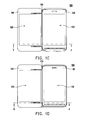
- Fig. 1A to Fig. 1F are operational views of a handheld electronic device according to one embodiment of the present invention.
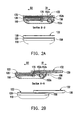
- Fig. 2A illustrates a cross sectional view of the handheld electric device of Fig. 1A taken along line B-B thereof and a side view of Fig. 1A .
- Fig. 2B illustrates a cross sectional view of the handheld electric device of Fig. 1B taken along line A-A thereof and a side view of Fig. 1B .
- Fig. 2C illustrates a cross sectional view of the handheld electric device of Fig. 1C taken along line C-C thereof and a side view of Fig. 1C .
- Fig. 2D illustrates a cross sectional view of the handheld electric device of Fig. 1D taken along line D-D thereof and a side view of Fig. 1D .
- Fig. 2E illustrates a cross sectional view of the handheld electric device of Fig. 1E taken along line E-E thereof and a side view of Fig. 1E .
- Fig. 2F illustrates a cross sectional view of the handheld electric device of Fig. 1F taken along line G-G thereof and a side view of Fig. 1F .
- Fig. 3A to Fig. 3F are partial, perspective views of the handheld electronic device of Fig. 1A to Fig. 1F , respectively.
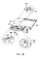
- Fig. 4 is an exploded view of the handheld electronic device of Fig. 1 .
- Fig. 1A to Fig. 1F are operational views of a handheld electronic device according to one embodiment of the present invention.
- Fig. 2A illustrates a cross sectional view of the handheld electric device of Fig. 1A taken along line B-B thereof and a side view of Fig. 1A .
- Fig. 2B illustrates a cross sectional view of the handheld electric device of Fig. 1B taken along line A-A thereof and a side view of Fig. 1B .
- Fig. 2C illustrates a cross sectional view of the handheld electric device of Fig. 1C taken along line C-C thereof and a side view of Fig. 1C .
- Fig. 2D illustrates a cross sectional view of the handheld electric device of Fig.
- Fig. 1D taken along line D-D thereof and a side view of Fig. 1D .
- Fig. 2E illustrates a cross sectional view of the handheld electric device of Fig. 1E taken along line E-E thereof and a side view of Fig. 1E .
- Fig. 2F illustrates a cross sectional view of the handheld electric device of Fig. 1F taken along line G-G thereof and a side view of Fig. 1F .
- Fig. 3A to Fig. 3F are partial, perspective views of the handheld electronic device of Fig. 1A to Fig. 1F , respectively.
- Fig. 4 is an exploded view of the handheld electronic device of Fig. 1 .
- the handheld electronic device 100 of the present embodiment includes a first body 110, a second body 120, a third body 130, a first rod 140 (two first rods 140 are illustrated in Fig. 4 as well as in Fig. 3B and Fig. 3F ), and an elevating mechanism 150.
- the first rod 140 includes a first end 142, a second end 144, and a pivot portion 146 (labeled in Fig. 4 ).
- the pivot portion 146 is located between the first end 142 and the second end 144 and is pivotably connected to the first body 110.
- the second body 120 is slidably disposed on the first body 110 and is coupled to the first end 142 of the first rod 140.
- the elevating mechanism 150 is disposed on the first body 110.
- the third body 130 is slidably disposed on a top of the elevating mechanism 150 and is coupled to the first rod 140.
- the second body 120 is stacked between the first body 110 and the third body 130 when the handheld electronic device 100 is in a retracted state (as shown in Fig. 2A ).
- the user may push the third body 130 to move relative to the first body 110 in a first operation direction D1, causing the electronic device to change from the states shown in Fig. 1A , Fig. 2A and Fig. 3A to the states shown in Fig. 1B , Fig. 2B and Fig. 3B , such that the second body 120 is partially exposed out of the third body 130.
- the user may then continue pushing the third body 130 to move relative to the first body 110 in the first operation direction D1 so as to drive the first rod 140 to pivot.
- the second body 120 is driven by the first rod 140 to move relative to the first body 110 in a second operation direction D2 opposite to the first operation direction D1, causing the electronic device to change from the states shown in Fig. 1B , Fig. 2B and Fig. 3B to the states shown in Fig. 1C , Fig. 2C and Fig. 3C , such that the second body 120 is completely exposed out of the third body 130.
- the third body 130 may be descended by the elevating mechanism 150, causing the electronic device to change from the states shown in Fig. 1C , Fig. 2C and Fig. 3C to the states shown in Fig. 1D , Fig. 2D and Fig. 3D , such that the third body 130 is moved toward the first body 110 and the handheld electronic device 100 is in a spread state.
- a display surface 132 of the third body 130 and a display surface 122 of the second body 120 can be joined to provide a larger display operation interface.
- the third body 130 is moved toward the first body 110 as shown in Fig.
- a top surface of the third body 130 is, for example, substantially coplanar with a top surface of the second body 120, such that the display surface 132 and the display surface 122 are adapted to respectively display two interactive images, each display one same image, or jointly display a complete image.
- the handheld electronic device 100 further includes a second rod 160 (two second rods 160 are illustrated).
- the second rod 160 is slidably disposed on the first body 110 and is coupled to the second end 144 of the first rod 140.
- the first rod 140 forms a slot 140a at the first end 142 thereof.
- the second body 120 includes a protruding post 124.
- the protruding post 24 is received in the slot 140a such that the second body 120 is coupled to the first rod 140.
- the handheld electronic device 100 further includes an elevating member 170 (two elevating members 170 are illustrated) and an elastic member 180 (two elastic members are illustrated).
- the elevating member 170 is elevatably disposed on the second rod 160.
- the elastic member 180 is, for example, a compression spring and is connected between the second rod 160 and the elevating member 170.
- the third body 130 moves relative to the first body 110 in the first direction D1 to the position shown in Fig. 2B , the third body 130 contacts one side of the elevating member 170.
- the third body 130 pushes the elevating member 170 so as to drive the second rod 160 to move from the position shown in Fig. 3B to the position shown in Fig. 3C , which in turn drives the first rod 140 to pivot from the state shown in Fig. 3B to the state shown in Fig. 3C , such that the second body 120 is driven to move from the position shown in Fig. 3B to the position shown in Fig. 3C .
- the third body 130 presses the elevating member 170 downward against the elastic force of the elastic member 180.
- the elevating member 170 can be moved between the position shown in Fig. 2C and the position shown in Fig. 2D thus allowing the third body 130 to successfully descend.
- the elevating mechanism 150 of the present embodiment includes a linkage mechanism 152 (labeled in Fig. 4 ).
- the linkage mechanism 152 is connected between the first body 110 and the third body 130 to drive the third body 130 to elevate relative to the first body 110.
- the linkage mechanism 152 includes a base 152a, a first link rod 152b (two first link rods are illustrated), a second link rod 152c (two second link rods are illustrated), and an elevating board 152d.
- the base 152a is fixed to the first body 110.
- the first link rod 152b and the second link rod 152c are pivotably mounted to the base 152a.
- the elevating board 152d is pivotably mounted to the first link rod 152b and pivotably mounted to the second link rod 152c.
- the third body 130 is slidably disposed on the elevating board 152d and is therefore adapted to move relative to the first body 110 in the first operation direction D1.
- the first link rod 152b and the second link rod 152c are adapted to pivot relative to the base 152a to drive the elevating board 152d and the third body 130 to descend to the position shown in Fig. 2D and move toward the first body 110.
- the elevating mechanism 150 of the present embodiment further includes an elastic member 154 and an elastic member 156.
- the elastic member 154 and elastic member 156 are, for example, torsion springs.
- the elastic member 154 is connected between the base 152a and the first link rod 152b, and the elastic member 156 is connected between the base 152a and the second link rod 152c.
- the user may press the third body 130 downward against the elastic force of the elastic member 154 and the elastic member 156 to drive the first link rod 152b and the second link rod 152c to pivot relative to the base 152a, thus causing the third body 130 to descend and move toward the first body 110 (as shown in Fig. 2D ).
- the handheld electronic device 100 of the present embodiment further includes a magnetic element 190a and a magnetic element 190b.
- the magnetic element 190a and magnetic element 190b are, for example, magnets and are mounted to the first body 110 and the third body 130, respectively.
- the magnetic element 190a is aligned with the magnetic element 190b such that the third body 130 is further positioned by the magnetic force between the magnetic element 190a and the magnetic element 190b.
- the third body 130 may be pushed from the position shown in Fig. 2D to the position shown in Fig. 2E in the first operation direction D1, such that the third body 130 no longer engages against the second body 12 and the magnetic element 190 moves away from the magnetic element 190b.
- the first link rod 152b and the second link rod 152c pivot relative to the base 152a under the influence of the resilient force of the elastic member 154 and the elastic member 156 to drive the third body 130 to elevate, thus facilitating the user pushing the third body 130 to the position shown in Fig. 2F in the second operation direction D2.
- the elevating member 170 is moved upward under the influence of the elastic force of the elastic member 180.
- the third body 130 contacts the side of the elevating member 170.
- the user may continue to push the third body 130 to the position shown in Fig. 3A in the second operation direction D2, causing the elevating member 170 to drive the second link rod 160 and the first link rod 140 to operate, which in turn drive the second body 120 to move from the position shown in Fig. 3F to the position shown in Fig. 3A to complete the closing operation of the handheld electronic device 100.
- the handheld electronic device 100 further includes a decorative plate 158.
- the decorative plate 158 is mounted to the first link rod 152b and positioned at one edge of the first body 110 and between the first body 110 and the third body 130 to cover the elevating mechanism 150 so as to maintain the beautiful appearance of the handheld electronic device 100.
- the second body is stacked between the first body and the third body.
- the third body can drive the second body to move by using a linkage mechanism such that the third body and the second body can move in opposite directions to expose the second body out of the third body.
- the third body then can descend to move toward the first body by using an elevating mechanism, such that the third body and the second body are connected to provide the handheld electronic device with a larger available display area.
- magnetic elements may be disposed on the first and second bodies, respectively, to provide a magnetic force to position the third body.
- Elastic members may further be disposed between the base and link rods of the linkage mechanism to provide an elastic force to drive the linkage mechanism to operate thus facilitating the operation of the handheld electronic device.
- the term "the invention”, “the present invention” or the like does not necessarily limit the claim scope to a specific embodiment, and the reference to particularly preferred exemplary embodiments of the invention does not imply a limitation on the invention, and no such limitation is to be inferred.
- the invention is limited only by the spirit and scope of the appended claims.
- the abstract of the disclosure is provided to comply with the rules requiring an abstract, which will allow a searcher to quickly ascertain the subject matter of the technical disclosure of any patent issued from this disclosure. It is submitted with the understanding that it will not be used to interpret or limit the scope or meaning of the claims. Any advantages and benefits described may not apply to all embodiments of the invention.
Landscapes
- Engineering & Computer Science (AREA)
- Physics & Mathematics (AREA)
- Theoretical Computer Science (AREA)
- Signal Processing (AREA)
- Mathematical Physics (AREA)
- Computer Hardware Design (AREA)
- Human Computer Interaction (AREA)
- General Engineering & Computer Science (AREA)
- General Physics & Mathematics (AREA)
- Telephone Set Structure (AREA)
- Casings For Electric Apparatus (AREA)
Abstract
Description
- The present invention relates to an electronic device, and more particularly, to a handheld electronic device.
- Following the development of information technology, desired information is easier and easier to acquire from electronic devices in daily life. On the other hand, various types of handheld electronic devices trend toward being light, thin, short and small. Due to the characteristic and advantage of being easy to carry, the electronic devices have been widely accepted and used in daily life.
- Taking the mobile phone as an example, in order for the mobile phone to be easily carried and satisfy various preferences and needs, there have been flip-type, rotation-type and slide-type mobile phones in addition to the traditional bar-type mobile phone. As far as the slide-type mobile phone is concerned, it consists of stacked upper and lower bodies that can slide relative to each other between spread and retracted states. Stacking the upper and lower bodies can help reduce the overall size, and the upper and lower bodies can be slid to the spread state in a particular operation mode. Following the development of touch-control display technology, the touch control display function of the mobile phone is being used to gradually replace the traditional key pad function. Therefore, it would be desirable to provide a mobile phone body having limited space with a larger available display area.
- Accordingly, the present invention is directed to a handheld electronic device which has a larger available display area and has a greater flexibility in configuring various components of the handheld electronic device.
- The present invention provides a handheld electronic device, which includes a first body, a first rod, a second body, an elevating mechanism, and a third body. The first rod has a first end, a second end, and a pivot portion. The pivot portion is positioned between the first end and the second end and is pivotably mounted to the first body. The second body is slidably disposed on the first body and is coupled to the first end. The elevating mechanism is disposed on the first body. The third body is slidably disposed on the elevating mechanism and is coupled to the first rod. The second body is stacked between the first body and the third body when the handheld electronic device is in a retracted state. When the third body moves relative to the first body in a first operation direction to drive the first rod to pivot, the second body is driven by the first rod to move relative to the first body in a second operation direction opposite to the first operation direction, such that the second body is exposed out of the third body. When the second body is exposed out of the third body, the third body is descended by the elevating mechanism to move toward the first body, such that the handheld electronic device turns into a spread state.
- In view of the foregoing, in embodiments of the present invention, the second body is stacked between the first body and the third body, and the third body can drive the second body to move by using a linkage mechanism such that the third body and the second body can move in opposite directions to expose the second body out of the third body. The third body then can descend to move toward the first body by using an elevating mechanism, such that the third body and the second body are connected to provide the handheld electronic device with a larger available display area. In addition, magnetic elements may be disposed on the first and second bodies, respectively, to provide a magnetic force to position the third body. Elastic members may further be disposed between the base and link rods of the linkage mechanism to provide an elastic force to drive the linkage mechanism to operate thus facilitating the operation of the handheld electronic device.
- Other objectives, features and advantages of the present invention will be further understood from the further technological features disclosed by the embodiments of the present invention wherein there are shown and described preferred embodiments of this invention, simply by way of illustration of modes best suited to carry out the invention.
-
Fig. 1A to Fig. 1F are operational views of a handheld electronic device according to one embodiment of the present invention. -
Fig. 2A illustrates a cross sectional view of the handheld electric device ofFig. 1A taken along line B-B thereof and a side view ofFig. 1A . -
Fig. 2B illustrates a cross sectional view of the handheld electric device ofFig. 1B taken along line A-A thereof and a side view ofFig. 1B . -
Fig. 2C illustrates a cross sectional view of the handheld electric device ofFig. 1C taken along line C-C thereof and a side view ofFig. 1C . -
Fig. 2D illustrates a cross sectional view of the handheld electric device ofFig. 1D taken along line D-D thereof and a side view ofFig. 1D . -
Fig. 2E illustrates a cross sectional view of the handheld electric device ofFig. 1E taken along line E-E thereof and a side view ofFig. 1E . -
Fig. 2F illustrates a cross sectional view of the handheld electric device ofFig. 1F taken along line G-G thereof and a side view ofFig. 1F . -
Fig. 3A to Fig. 3F are partial, perspective views of the handheld electronic device ofFig. 1A to Fig. 1F , respectively. -
Fig. 4 is an exploded view of the handheld electronic device ofFig. 1 . - In the following detailed description of the preferred embodiments, reference is made to the accompanying drawings which form a part hereof, and in which are shown by way of illustration specific embodiments in which the invention may be practiced. In this regard, directional terminology, such as "top," "bottom," "front," "back," etc., is used with reference to the orientation of the Figure(s) being described. The components of the present invention can be positioned in a number of different orientations. As such, the directional terminology is used for purposes of illustration and is in no way limiting. On the other hand, the drawings are only schematic and the sizes of components may be exaggerated for clarity. It is to be understood that other embodiments may be utilized and structural changes may be made without departing from the scope of the present invention. Also, it is to be understood that the phraseology and terminology used herein are for the purposes of description and should not be regarded as limiting. The use of "including," "comprising," or "having" and variations thereof herein is meant to encompass the items listed thereafter and equivalents thereof as well as additional items. Unless limited otherwise, the terms "connected," "coupled," and "mounted" and variations thereof herein are used broadly and encompass direct and indirect connections, couplings, and mountings. Similarly, the terms "facing," "faces" and variations thereof herein are used broadly and encompass direct and indirect facing, and "adjacent to" and variations thereof herein are used broadly and encompass directly and indirectly "adjacent to". Therefore, the description of "A" component facing "B" component herein may contain the situations that "A" component directly faces "B" component or one or more additional components are between "A" component and "B" component. Also, the description of "A" component "adjacent to" "B" component herein may contain the situations that "A" component is directly "adjacent to" "B" component or one or more additional components are between "A" component and "B" component. Accordingly, the drawings and descriptions will be regarded as illustrative in nature and not as restrictive.
-
Fig. 1A to Fig. 1F are operational views of a handheld electronic device according to one embodiment of the present invention.Fig. 2A illustrates a cross sectional view of the handheld electric device ofFig. 1A taken along line B-B thereof and a side view ofFig. 1A .Fig. 2B illustrates a cross sectional view of the handheld electric device ofFig. 1B taken along line A-A thereof and a side view ofFig. 1B .Fig. 2C illustrates a cross sectional view of the handheld electric device ofFig. 1C taken along line C-C thereof and a side view ofFig. 1C .Fig. 2D illustrates a cross sectional view of the handheld electric device ofFig. 1D taken along line D-D thereof and a side view ofFig. 1D .Fig. 2E illustrates a cross sectional view of the handheld electric device ofFig. 1E taken along line E-E thereof and a side view ofFig. 1E .Fig. 2F illustrates a cross sectional view of the handheld electric device ofFig. 1F taken along line G-G thereof and a side view ofFig. 1F .Fig. 3A to Fig. 3F are partial, perspective views of the handheld electronic device ofFig. 1A to Fig. 1F , respectively.Fig. 4 is an exploded view of the handheld electronic device ofFig. 1 . - Referring to
Fig. 1A ,Fig. 2A ,Fig. 3A andFig. 4 , the handheldelectronic device 100 of the present embodiment includes afirst body 110, asecond body 120, athird body 130, a first rod 140 (twofirst rods 140 are illustrated inFig. 4 as well as inFig. 3B andFig. 3F ), and an elevatingmechanism 150. Thefirst rod 140 includes afirst end 142, asecond end 144, and a pivot portion 146 (labeled inFig. 4 ). Thepivot portion 146 is located between thefirst end 142 and thesecond end 144 and is pivotably connected to thefirst body 110. Thesecond body 120 is slidably disposed on thefirst body 110 and is coupled to thefirst end 142 of thefirst rod 140. The elevatingmechanism 150 is disposed on thefirst body 110. Thethird body 130 is slidably disposed on a top of the elevatingmechanism 150 and is coupled to thefirst rod 140. Thesecond body 120 is stacked between thefirst body 110 and thethird body 130 when the handheldelectronic device 100 is in a retracted state (as shown inFig. 2A ). - The user may push the
third body 130 to move relative to thefirst body 110 in a first operation direction D1, causing the electronic device to change from the states shown inFig. 1A ,Fig. 2A andFig. 3A to the states shown inFig. 1B ,Fig. 2B andFig. 3B , such that thesecond body 120 is partially exposed out of thethird body 130. The user may then continue pushing thethird body 130 to move relative to thefirst body 110 in the first operation direction D1 so as to drive thefirst rod 140 to pivot. At this time, thesecond body 120 is driven by thefirst rod 140 to move relative to thefirst body 110 in a second operation direction D2 opposite to the first operation direction D1, causing the electronic device to change from the states shown inFig. 1B ,Fig. 2B andFig. 3B to the states shown inFig. 1C ,Fig. 2C andFig. 3C , such that thesecond body 120 is completely exposed out of thethird body 130. - When the
second body 120 is completely exposed out of thethird body 130, thethird body 130 may be descended by the elevatingmechanism 150, causing the electronic device to change from the states shown inFig. 1C ,Fig. 2C andFig. 3C to the states shown inFig. 1D ,Fig. 2D andFig. 3D , such that thethird body 130 is moved toward thefirst body 110 and the handheldelectronic device 100 is in a spread state. As a result, adisplay surface 132 of thethird body 130 and adisplay surface 122 of thesecond body 120 can be joined to provide a larger display operation interface. Specifically, when thethird body 130 is moved toward thefirst body 110 as shown inFig. 2D , a top surface of thethird body 130 is, for example, substantially coplanar with a top surface of thesecond body 120, such that thedisplay surface 132 and thedisplay surface 122 are adapted to respectively display two interactive images, each display one same image, or jointly display a complete image. - Referring to
Fig. 3B andFig. 4 , in the present embodiment, the handheldelectronic device 100 further includes a second rod 160 (twosecond rods 160 are illustrated). Thesecond rod 160 is slidably disposed on thefirst body 110 and is coupled to thesecond end 144 of thefirst rod 140. Thefirst rod 140 forms a slot 140a at thefirst end 142 thereof. Thesecond body 120 includes a protrudingpost 124. The protruding post 24 is received in the slot 140a such that thesecond body 120 is coupled to thefirst rod 140. In addition, the handheldelectronic device 100 further includes an elevating member 170 (two elevatingmembers 170 are illustrated) and an elastic member 180 (two elastic members are illustrated). The elevatingmember 170 is elevatably disposed on thesecond rod 160. Theelastic member 180 is, for example, a compression spring and is connected between thesecond rod 160 and the elevatingmember 170. - When the
third body 130 moves relative to thefirst body 110 in the first direction D1 to the position shown inFig. 2B , thethird body 130 contacts one side of the elevatingmember 170. During the course of continuing movement of thethird body 130 relative to thefirst body 110 in the first direction D1 to the position shown inFig. 2C , thethird body 130 pushes the elevatingmember 170 so as to drive thesecond rod 160 to move from the position shown inFig. 3B to the position shown inFig. 3C , which in turn drives thefirst rod 140 to pivot from the state shown inFig. 3B to the state shown inFig. 3C , such that thesecond body 120 is driven to move from the position shown inFig. 3B to the position shown inFig. 3C . In addition, during the course of the third body's descending and moving toward thefirst body 110 by means of the elevatingmechanism 150, thethird body 130 presses the elevatingmember 170 downward against the elastic force of theelastic member 180. In other words, by means of the elastic deformation characteristics of theelastic member 170, the elevatingmember 170 can be moved between the position shown inFig. 2C and the position shown inFig. 2D thus allowing thethird body 130 to successfully descend. - The elevating
mechanism 150 of the present embodiment includes a linkage mechanism 152 (labeled inFig. 4 ). The linkage mechanism 152 is connected between thefirst body 110 and thethird body 130 to drive thethird body 130 to elevate relative to thefirst body 110. Specifically, the linkage mechanism 152 includes abase 152a, afirst link rod 152b (two first link rods are illustrated), asecond link rod 152c (two second link rods are illustrated), and an elevatingboard 152d. Thebase 152a is fixed to thefirst body 110. Thefirst link rod 152b and thesecond link rod 152c are pivotably mounted to thebase 152a. The elevatingboard 152d is pivotably mounted to thefirst link rod 152b and pivotably mounted to thesecond link rod 152c. Thethird body 130 is slidably disposed on the elevatingboard 152d and is therefore adapted to move relative to thefirst body 110 in the first operation direction D1. When thesecond body 120 is exposed out of thethird body 130 as shown inFig. 2C , thefirst link rod 152b and thesecond link rod 152c are adapted to pivot relative to thebase 152a to drive the elevatingboard 152d and thethird body 130 to descend to the position shown inFig. 2D and move toward thefirst body 110. - Referring to
Fig. 4 , the elevatingmechanism 150 of the present embodiment further includes anelastic member 154 and anelastic member 156. Theelastic member 154 andelastic member 156 are, for example, torsion springs. Theelastic member 154 is connected between thebase 152a and thefirst link rod 152b, and theelastic member 156 is connected between thebase 152a and thesecond link rod 152c. When thesecond body 120 is exposed out of thethird body 130 as shown inFig. 2C , the user may press thethird body 130 downward against the elastic force of theelastic member 154 and theelastic member 156 to drive thefirst link rod 152b and thesecond link rod 152c to pivot relative to thebase 152a, thus causing thethird body 130 to descend and move toward the first body 110 (as shown inFig. 2D ). - When the handheld
electronic device 100 is in the spread state shown inFig. 2D , the side of thethird body 130 engages against the side of thesecond body 120 to resist the elastic force of theelastic member 154 and theelastic member 156 and is therefore positioned at the position shown inFig. 2D . In addition, referring toFig. 3B andFig. 4 , the handheldelectronic device 100 of the present embodiment further includes amagnetic element 190a and amagnetic element 190b. Themagnetic element 190a andmagnetic element 190b are, for example, magnets and are mounted to thefirst body 110 and thethird body 130, respectively. When thethird body 130 is at the position shown inFig. 2D , themagnetic element 190a is aligned with themagnetic element 190b such that thethird body 130 is further positioned by the magnetic force between themagnetic element 190a and themagnetic element 190b. - To close the handheld
electronic device 100 after operation, thethird body 130 may be pushed from the position shown inFig. 2D to the position shown inFig. 2E in the first operation direction D1, such that thethird body 130 no longer engages against the second body 12 and the magnetic element 190 moves away from themagnetic element 190b. At this time, thefirst link rod 152b and thesecond link rod 152c pivot relative to thebase 152a under the influence of the resilient force of theelastic member 154 and theelastic member 156 to drive thethird body 130 to elevate, thus facilitating the user pushing thethird body 130 to the position shown inFig. 2F in the second operation direction D2. During the course of elevating of thethird body 130, the elevatingmember 170 is moved upward under the influence of the elastic force of theelastic member 180. When thethird body 130 is at the position shown inFig. 2F , thethird body 130 contacts the side of the elevatingmember 170. At this time, the user may continue to push thethird body 130 to the position shown inFig. 3A in the second operation direction D2, causing the elevatingmember 170 to drive thesecond link rod 160 and thefirst link rod 140 to operate, which in turn drive thesecond body 120 to move from the position shown inFig. 3F to the position shown inFig. 3A to complete the closing operation of the handheldelectronic device 100. - In the present embodiment, the handheld
electronic device 100 further includes adecorative plate 158. Thedecorative plate 158 is mounted to thefirst link rod 152b and positioned at one edge of thefirst body 110 and between thefirst body 110 and thethird body 130 to cover the elevatingmechanism 150 so as to maintain the beautiful appearance of the handheldelectronic device 100. - In summary, in embodiments of the present invention, the second body is stacked between the first body and the third body. The third body can drive the second body to move by using a linkage mechanism such that the third body and the second body can move in opposite directions to expose the second body out of the third body. The third body then can descend to move toward the first body by using an elevating mechanism, such that the third body and the second body are connected to provide the handheld electronic device with a larger available display area. In addition, magnetic elements may be disposed on the first and second bodies, respectively, to provide a magnetic force to position the third body. Elastic members may further be disposed between the base and link rods of the linkage mechanism to provide an elastic force to drive the linkage mechanism to operate thus facilitating the operation of the handheld electronic device.
- The foregoing description of the preferred embodiments of the invention has been presented for purposes of illustration and description. It is not intended to be exhaustive or to limit the invention to the precise form or to exemplary embodiments disclosed. Accordingly, the foregoing description should be regarded as illustrative rather than restrictive. Obviously, many modifications and variations will be apparent to practitioners skilled in this art. The embodiments are chosen and described in order to best explain the principles of the invention and its best mode practical application, thereby to enable persons skilled in the art to understand the invention for various embodiments and with various modifications as are suited to the particular use or implementation contemplated. It is intended that the scope of the invention be defined by the claims appended hereto and their equivalents in which all terms are meant in their broadest reasonable sense unless otherwise indicated. Therefore, the term "the invention", "the present invention" or the like does not necessarily limit the claim scope to a specific embodiment, and the reference to particularly preferred exemplary embodiments of the invention does not imply a limitation on the invention, and no such limitation is to be inferred. The invention is limited only by the spirit and scope of the appended claims. The abstract of the disclosure is provided to comply with the rules requiring an abstract, which will allow a searcher to quickly ascertain the subject matter of the technical disclosure of any patent issued from this disclosure. It is submitted with the understanding that it will not be used to interpret or limit the scope or meaning of the claims. Any advantages and benefits described may not apply to all embodiments of the invention. It should be appreciated that variations may be made in the embodiments described by persons skilled in the art without departing from the scope of the present invention as defined by the following claims. Moreover, no element and component in the present disclosure is intended to be dedicated to the public regardless of whether the element or component is explicitly recited in the following claims.
Claims (14)
- A handheld electronic device comprising:a first body;a first rod having a first end, a second end, and a pivot portion, wherein the pivot portion is positioned between the first end and the second end and is pivotably mounted to the first body;a second body slidably disposed on the first body and coupled to the first end;an elevating mechanism disposed on the first body; anda third body slidably disposed on the elevating mechanism and is coupled to the first rod, wherein the second body is stacked between the first body and the third body when the handheld electronic device is in a retracted state, when the third body moves relative to the first body in a first operation direction to drive the first rod to pivot, the second body is driven by the first rod to move relative to the first body in a second operation direction opposite to the first operation direction such that the second body is exposed out of the third body, when the second body is exposed out of the third body, the third body is descended by the elevating mechanism to move toward the first body such that the handheld electronic device turns into a spread state.
- The handheld electronic device according to claim 1, wherein when the handheld electronic device is in the spread state, a top surface of the third body and a top surface of the second body are substantially coplanar.
- The handheld electronic device according to claim 2, wherein the second body has a first display surface, the third body has a second display surface, when the handheld electronic device is in the spread state, the first display surface and the second display surface are adapted to respectively display two interactive images, each display one same image, or jointly display a complete image.
- The handheld electronic device according to claim 1, wherein the first rod has a slot at the first end, the second body has a protruding post, and the protruding post is received in the slot.
- The handheld electronic device according to claim 1, further comprising a second rod slidably disposed on the first body and coupled to the second end, wherein when the third body moves relative to the first body in the first operation direction, the third body pushes the second rod to drive the first rod to pivot.
- The handheld electronic device according to claim 5, further comprising:an elevating member elevatably disposed on the second rod; andan elastic member connected between the second rod and the elevating member, wherein when the third body moves relative to the first body in the first operation direction, the third body pushes the elevating member to drive the second rod, when the third body is descended by the elevating mechanism to move toward the first body, the third body presses the elevating member downward against the elastic force of the elastic member.
- The handheld electronic device according to claim 6, wherein the elastic member is a compression spring.
- The handheld electronic device according to claim 5, wherein the first rod has a slot at the second end, the second rod includes a protruding post, and the protruding post is received in the slot.
- The handheld electronic device according to claim 1, wherein the elevating mechanism includes a linkage mechanism connected between the first body and the third body.
- The handheld electronic device according to claim 9, wherein the linkage mechanism comprises:a base fixed to the first body;a first link rod pivotably mounted to the base;a second link rod pivotably mounted to the base; andan elevating board pivotably mounted to the first link rod and the second link rod, wherein the third body is slidably disposed on the elevating board, and when the second body is exposed out of the third body, the first link rod and the second link rod pivot relative to the base to drive the elevating board and the third body to descend to move toward the first body.
- The handheld electronic device according to claim 10, wherein the elevating mechanism further comprises:a first elastic member connected between the base and the first link rod; anda second elastic member connected between the base and the second link rod, wherein when the second body is exposed out of the third body, the first link rod and the second link rod pivot relative to the base against the elastic force of the first elastic member and the second elastic member, respectively, to drive the elevating board and the third body to descend to move toward the first body.
- The handheld electronic device according to claim 11, wherein the first elastic member and the second elastic member are torsion springs.
- The handheld electronic device according to claim 10, further comprising a decorative plate disposed at an edge of the first body and between the first body and the second body to cover the elevating mechanism.
- The handheld electronic device according to claim 13, wherein the decorative plate is mounted to the first link rod.
Applications Claiming Priority (1)
| Application Number | Priority Date | Filing Date | Title |
|---|---|---|---|
| TW099125135A TWI376928B (en) | 2010-07-29 | 2010-07-29 | Handheld electronic device |
Publications (2)
| Publication Number | Publication Date |
|---|---|
| EP2413576A1 true EP2413576A1 (en) | 2012-02-01 |
| EP2413576B1 EP2413576B1 (en) | 2013-02-20 |
Family
ID=44650805
Family Applications (1)
| Application Number | Title | Priority Date | Filing Date |
|---|---|---|---|
| EP11006232A Active EP2413576B1 (en) | 2010-07-29 | 2011-07-28 | Handheld electronic device |
Country Status (3)
| Country | Link |
|---|---|
| US (1) | US8306586B2 (en) |
| EP (1) | EP2413576B1 (en) |
| TW (1) | TWI376928B (en) |
Families Citing this family (5)
| Publication number | Priority date | Publication date | Assignee | Title |
|---|---|---|---|---|
| USD664130S1 (en) * | 2010-12-13 | 2012-07-24 | Samsung Electronics Co., Ltd. | LTE terminal |
| US8724316B2 (en) * | 2011-11-24 | 2014-05-13 | Htc Corporation | Handheld electronic device |
| US8549708B1 (en) * | 2012-07-05 | 2013-10-08 | Khvatec Co., Ltd. | Long stroke tilting hinge module for portable terminal |
| CN113395845B (en) * | 2021-06-11 | 2022-07-12 | 维沃移动通信有限公司 | Electronic device |
| CN119920175B (en) * | 2025-03-17 | 2025-11-21 | 惠科股份有限公司 | Display devices |
Citations (5)
| Publication number | Priority date | Publication date | Assignee | Title |
|---|---|---|---|---|
| WO2009034907A1 (en) * | 2007-09-13 | 2009-03-19 | Kyocera Corporation | Portable communication terminal |
| WO2010023354A1 (en) * | 2008-08-29 | 2010-03-04 | Nokia Corporation | User interfaces and associated apparatus and methods |
| EP2175619A1 (en) * | 2008-10-08 | 2010-04-14 | HTC Corporation | Portable electronic device having two slidable bodies |
| EP2194693A1 (en) * | 2008-12-05 | 2010-06-09 | HTC Corporation | Handheld electronic device |
| US20100259463A1 (en) * | 2009-04-10 | 2010-10-14 | Hong Fu Jin Precision Industry (Shenzhen) Co., Ltd. | Electronic device with extensible screen |
Family Cites Families (8)
| Publication number | Priority date | Publication date | Assignee | Title |
|---|---|---|---|---|
| JP4193411B2 (en) * | 2002-04-26 | 2008-12-10 | 日本電気株式会社 | Mobile phone |
| EP1867143B1 (en) * | 2005-04-06 | 2011-11-02 | Nokia Corporation | Extensible mobile electronic device |
| US7539526B2 (en) * | 2005-08-17 | 2009-05-26 | Nokia Corporation | Foldable keyboard for an electronic device |
| KR100744295B1 (en) * | 2005-09-27 | 2007-07-30 | 삼성전자주식회사 | Handheld terminal |
| US7627337B2 (en) | 2006-04-17 | 2009-12-01 | Nokia Corporation | Dual lever slide mechanism for extendible device housings |
| TWM335100U (en) * | 2007-12-19 | 2008-06-21 | Mobinnova Hong Kong Ltd | Portable electronic device |
| US8860632B2 (en) * | 2008-09-08 | 2014-10-14 | Qualcomm Incorporated | Multi-panel device with configurable interface |
| US9154592B2 (en) * | 2010-02-05 | 2015-10-06 | Microsoft Technology Licensing, Llc | Moveable housing of a mobile communications device |
-
2010
- 2010-07-29 TW TW099125135A patent/TWI376928B/en active
-
2011
- 2011-01-26 US US13/013,838 patent/US8306586B2/en active Active
- 2011-07-28 EP EP11006232A patent/EP2413576B1/en active Active
Patent Citations (5)
| Publication number | Priority date | Publication date | Assignee | Title |
|---|---|---|---|---|
| WO2009034907A1 (en) * | 2007-09-13 | 2009-03-19 | Kyocera Corporation | Portable communication terminal |
| WO2010023354A1 (en) * | 2008-08-29 | 2010-03-04 | Nokia Corporation | User interfaces and associated apparatus and methods |
| EP2175619A1 (en) * | 2008-10-08 | 2010-04-14 | HTC Corporation | Portable electronic device having two slidable bodies |
| EP2194693A1 (en) * | 2008-12-05 | 2010-06-09 | HTC Corporation | Handheld electronic device |
| US20100259463A1 (en) * | 2009-04-10 | 2010-10-14 | Hong Fu Jin Precision Industry (Shenzhen) Co., Ltd. | Electronic device with extensible screen |
Also Published As
| Publication number | Publication date |
|---|---|
| US8306586B2 (en) | 2012-11-06 |
| EP2413576B1 (en) | 2013-02-20 |
| TWI376928B (en) | 2012-11-11 |
| TW201206142A (en) | 2012-02-01 |
| US20120028693A1 (en) | 2012-02-02 |
Similar Documents
| Publication | Publication Date | Title |
|---|---|---|
| TWI255682B (en) | Sliding-type electronic device with a semi-automatic opening mechanism | |
| US8140135B2 (en) | Handheld electronic device | |
| US9001500B2 (en) | Sliding mechanism and electronic device using same | |
| US20090321609A1 (en) | Portable Electronics | |
| US8306586B2 (en) | Handheld electronic device | |
| EP2267986A1 (en) | Electronic device and moving mechanism thereof | |
| CN101061693A (en) | Slidable and foldable electronic device and corresponding method | |
| US8254093B2 (en) | Sliding mechanism and electronic device having the same | |
| US7957779B2 (en) | Slidable mobile phone | |
| US8183459B2 (en) | Handheld electronic device and rising mechanism | |
| EP2410718B1 (en) | Handheld electronic device | |
| US20070254691A1 (en) | Sliding mechanism for use with an electronic device | |
| US8289705B2 (en) | Electronic device | |
| US8280464B2 (en) | Handheld electronic device | |
| TW202008414A (en) | Keyswitch | |
| CN101754619B (en) | handheld electronic device | |
| TW200850110A (en) | Communication device with stickup structure | |
| EP2290917A1 (en) | Handheld electronic device | |
| CN101242436A (en) | Sliding cover type mobile phone | |
| CN101730423B (en) | Portable electronic device | |
| CN101227806A (en) | Hand-held electronic device | |
| CN102340951B (en) | handheld electronic device | |
| CN102347996B (en) | handheld electronic device | |
| CN2645355Y (en) | push-button hinge | |
| CN102256465A (en) | Hand-held electronic device |
Legal Events
| Date | Code | Title | Description |
|---|---|---|---|
| 17P | Request for examination filed |
Effective date: 20110728 |
|
| AK | Designated contracting states |
Kind code of ref document: A1 Designated state(s): AL AT BE BG CH CY CZ DE DK EE ES FI FR GB GR HR HU IE IS IT LI LT LU LV MC MK MT NL NO PL PT RO RS SE SI SK SM TR |
|
| AX | Request for extension of the european patent |
Extension state: BA ME |
|
| PUAI | Public reference made under article 153(3) epc to a published international application that has entered the european phase |
Free format text: ORIGINAL CODE: 0009012 |
|
| 17Q | First examination report despatched |
Effective date: 20120116 |
|
| RIC1 | Information provided on ipc code assigned before grant |
Ipc: H04M 1/02 20060101AFI20120806BHEP Ipc: G06F 1/16 20060101ALI20120806BHEP |
|
| GRAP | Despatch of communication of intention to grant a patent |
Free format text: ORIGINAL CODE: EPIDOSNIGR1 |
|
| GRAS | Grant fee paid |
Free format text: ORIGINAL CODE: EPIDOSNIGR3 |
|
| GRAA | (expected) grant |
Free format text: ORIGINAL CODE: 0009210 |
|
| AK | Designated contracting states |
Kind code of ref document: B1 Designated state(s): AL AT BE BG CH CY CZ DE DK EE ES FI FR GB GR HR HU IE IS IT LI LT LU LV MC MK MT NL NO PL PT RO RS SE SI SK SM TR |
|
| REG | Reference to a national code |
Ref country code: GB Ref legal event code: FG4D |
|
| REG | Reference to a national code |
Ref country code: CH Ref legal event code: EP |
|
| REG | Reference to a national code |
Ref country code: AT Ref legal event code: REF Ref document number: 597967 Country of ref document: AT Kind code of ref document: T Effective date: 20130315 |
|
| REG | Reference to a national code |
Ref country code: IE Ref legal event code: FG4D |
|
| REG | Reference to a national code |
Ref country code: DE Ref legal event code: R096 Ref document number: 602011000903 Country of ref document: DE Effective date: 20130418 |
|
| REG | Reference to a national code |
Ref country code: NL Ref legal event code: T3 |
|
| REG | Reference to a national code |
Ref country code: AT Ref legal event code: MK05 Ref document number: 597967 Country of ref document: AT Kind code of ref document: T Effective date: 20130220 |
|
| REG | Reference to a national code |
Ref country code: LT Ref legal event code: MG4D |
|
| PG25 | Lapsed in a contracting state [announced via postgrant information from national office to epo] |
Ref country code: AT Free format text: LAPSE BECAUSE OF FAILURE TO SUBMIT A TRANSLATION OF THE DESCRIPTION OR TO PAY THE FEE WITHIN THE PRESCRIBED TIME-LIMIT Effective date: 20130220 Ref country code: LT Free format text: LAPSE BECAUSE OF FAILURE TO SUBMIT A TRANSLATION OF THE DESCRIPTION OR TO PAY THE FEE WITHIN THE PRESCRIBED TIME-LIMIT Effective date: 20130220 Ref country code: SE Free format text: LAPSE BECAUSE OF FAILURE TO SUBMIT A TRANSLATION OF THE DESCRIPTION OR TO PAY THE FEE WITHIN THE PRESCRIBED TIME-LIMIT Effective date: 20130220 Ref country code: IS Free format text: LAPSE BECAUSE OF FAILURE TO SUBMIT A TRANSLATION OF THE DESCRIPTION OR TO PAY THE FEE WITHIN THE PRESCRIBED TIME-LIMIT Effective date: 20130620 Ref country code: ES Free format text: LAPSE BECAUSE OF FAILURE TO SUBMIT A TRANSLATION OF THE DESCRIPTION OR TO PAY THE FEE WITHIN THE PRESCRIBED TIME-LIMIT Effective date: 20130531 Ref country code: NO Free format text: LAPSE BECAUSE OF FAILURE TO SUBMIT A TRANSLATION OF THE DESCRIPTION OR TO PAY THE FEE WITHIN THE PRESCRIBED TIME-LIMIT Effective date: 20130520 Ref country code: BG Free format text: LAPSE BECAUSE OF FAILURE TO SUBMIT A TRANSLATION OF THE DESCRIPTION OR TO PAY THE FEE WITHIN THE PRESCRIBED TIME-LIMIT Effective date: 20130520 |
|
| PG25 | Lapsed in a contracting state [announced via postgrant information from national office to epo] |
Ref country code: LV Free format text: LAPSE BECAUSE OF FAILURE TO SUBMIT A TRANSLATION OF THE DESCRIPTION OR TO PAY THE FEE WITHIN THE PRESCRIBED TIME-LIMIT Effective date: 20130220 Ref country code: GR Free format text: LAPSE BECAUSE OF FAILURE TO SUBMIT A TRANSLATION OF THE DESCRIPTION OR TO PAY THE FEE WITHIN THE PRESCRIBED TIME-LIMIT Effective date: 20130521 Ref country code: PL Free format text: LAPSE BECAUSE OF FAILURE TO SUBMIT A TRANSLATION OF THE DESCRIPTION OR TO PAY THE FEE WITHIN THE PRESCRIBED TIME-LIMIT Effective date: 20130220 Ref country code: FI Free format text: LAPSE BECAUSE OF FAILURE TO SUBMIT A TRANSLATION OF THE DESCRIPTION OR TO PAY THE FEE WITHIN THE PRESCRIBED TIME-LIMIT Effective date: 20130220 Ref country code: PT Free format text: LAPSE BECAUSE OF FAILURE TO SUBMIT A TRANSLATION OF THE DESCRIPTION OR TO PAY THE FEE WITHIN THE PRESCRIBED TIME-LIMIT Effective date: 20130620 Ref country code: SI Free format text: LAPSE BECAUSE OF FAILURE TO SUBMIT A TRANSLATION OF THE DESCRIPTION OR TO PAY THE FEE WITHIN THE PRESCRIBED TIME-LIMIT Effective date: 20130220 Ref country code: BE Free format text: LAPSE BECAUSE OF FAILURE TO SUBMIT A TRANSLATION OF THE DESCRIPTION OR TO PAY THE FEE WITHIN THE PRESCRIBED TIME-LIMIT Effective date: 20130220 |
|
| PG25 | Lapsed in a contracting state [announced via postgrant information from national office to epo] |
Ref country code: RS Free format text: LAPSE BECAUSE OF FAILURE TO SUBMIT A TRANSLATION OF THE DESCRIPTION OR TO PAY THE FEE WITHIN THE PRESCRIBED TIME-LIMIT Effective date: 20130220 Ref country code: HR Free format text: LAPSE BECAUSE OF FAILURE TO SUBMIT A TRANSLATION OF THE DESCRIPTION OR TO PAY THE FEE WITHIN THE PRESCRIBED TIME-LIMIT Effective date: 20130220 |
|
| PG25 | Lapsed in a contracting state [announced via postgrant information from national office to epo] |
Ref country code: CZ Free format text: LAPSE BECAUSE OF FAILURE TO SUBMIT A TRANSLATION OF THE DESCRIPTION OR TO PAY THE FEE WITHIN THE PRESCRIBED TIME-LIMIT Effective date: 20130220 Ref country code: RO Free format text: LAPSE BECAUSE OF FAILURE TO SUBMIT A TRANSLATION OF THE DESCRIPTION OR TO PAY THE FEE WITHIN THE PRESCRIBED TIME-LIMIT Effective date: 20130220 Ref country code: SK Free format text: LAPSE BECAUSE OF FAILURE TO SUBMIT A TRANSLATION OF THE DESCRIPTION OR TO PAY THE FEE WITHIN THE PRESCRIBED TIME-LIMIT Effective date: 20130220 Ref country code: EE Free format text: LAPSE BECAUSE OF FAILURE TO SUBMIT A TRANSLATION OF THE DESCRIPTION OR TO PAY THE FEE WITHIN THE PRESCRIBED TIME-LIMIT Effective date: 20130220 Ref country code: DK Free format text: LAPSE BECAUSE OF FAILURE TO SUBMIT A TRANSLATION OF THE DESCRIPTION OR TO PAY THE FEE WITHIN THE PRESCRIBED TIME-LIMIT Effective date: 20130220 |
|
| PLBE | No opposition filed within time limit |
Free format text: ORIGINAL CODE: 0009261 |
|
| STAA | Information on the status of an ep patent application or granted ep patent |
Free format text: STATUS: NO OPPOSITION FILED WITHIN TIME LIMIT |
|
| PG25 | Lapsed in a contracting state [announced via postgrant information from national office to epo] |
Ref country code: IT Free format text: LAPSE BECAUSE OF FAILURE TO SUBMIT A TRANSLATION OF THE DESCRIPTION OR TO PAY THE FEE WITHIN THE PRESCRIBED TIME-LIMIT Effective date: 20130220 |
|
| 26N | No opposition filed |
Effective date: 20131121 |
|
| PG25 | Lapsed in a contracting state [announced via postgrant information from national office to epo] |
Ref country code: MC Free format text: LAPSE BECAUSE OF FAILURE TO SUBMIT A TRANSLATION OF THE DESCRIPTION OR TO PAY THE FEE WITHIN THE PRESCRIBED TIME-LIMIT Effective date: 20130220 |
|
| REG | Reference to a national code |
Ref country code: DE Ref legal event code: R097 Ref document number: 602011000903 Country of ref document: DE Effective date: 20131121 |
|
| REG | Reference to a national code |
Ref country code: IE Ref legal event code: MM4A |
|
| PG25 | Lapsed in a contracting state [announced via postgrant information from national office to epo] |
Ref country code: IE Free format text: LAPSE BECAUSE OF NON-PAYMENT OF DUE FEES Effective date: 20130728 |
|
| REG | Reference to a national code |
Ref country code: CH Ref legal event code: PL |
|
| PG25 | Lapsed in a contracting state [announced via postgrant information from national office to epo] |
Ref country code: CH Free format text: LAPSE BECAUSE OF NON-PAYMENT OF DUE FEES Effective date: 20140731 Ref country code: LI Free format text: LAPSE BECAUSE OF NON-PAYMENT OF DUE FEES Effective date: 20140731 |
|
| PG25 | Lapsed in a contracting state [announced via postgrant information from national office to epo] |
Ref country code: SM Free format text: LAPSE BECAUSE OF FAILURE TO SUBMIT A TRANSLATION OF THE DESCRIPTION OR TO PAY THE FEE WITHIN THE PRESCRIBED TIME-LIMIT Effective date: 20130220 |
|
| PG25 | Lapsed in a contracting state [announced via postgrant information from national office to epo] |
Ref country code: MT Free format text: LAPSE BECAUSE OF FAILURE TO SUBMIT A TRANSLATION OF THE DESCRIPTION OR TO PAY THE FEE WITHIN THE PRESCRIBED TIME-LIMIT Effective date: 20130220 Ref country code: TR Free format text: LAPSE BECAUSE OF FAILURE TO SUBMIT A TRANSLATION OF THE DESCRIPTION OR TO PAY THE FEE WITHIN THE PRESCRIBED TIME-LIMIT Effective date: 20130220 Ref country code: CY Free format text: LAPSE BECAUSE OF FAILURE TO SUBMIT A TRANSLATION OF THE DESCRIPTION OR TO PAY THE FEE WITHIN THE PRESCRIBED TIME-LIMIT Effective date: 20130220 |
|
| PG25 | Lapsed in a contracting state [announced via postgrant information from national office to epo] |
Ref country code: MK Free format text: LAPSE BECAUSE OF FAILURE TO SUBMIT A TRANSLATION OF THE DESCRIPTION OR TO PAY THE FEE WITHIN THE PRESCRIBED TIME-LIMIT Effective date: 20130220 Ref country code: LU Free format text: LAPSE BECAUSE OF NON-PAYMENT OF DUE FEES Effective date: 20130728 Ref country code: HU Free format text: LAPSE BECAUSE OF FAILURE TO SUBMIT A TRANSLATION OF THE DESCRIPTION OR TO PAY THE FEE WITHIN THE PRESCRIBED TIME-LIMIT; INVALID AB INITIO Effective date: 20110728 |
|
| REG | Reference to a national code |
Ref country code: FR Ref legal event code: PLFP Year of fee payment: 6 |
|
| REG | Reference to a national code |
Ref country code: FR Ref legal event code: PLFP Year of fee payment: 7 |
|
| REG | Reference to a national code |
Ref country code: FR Ref legal event code: PLFP Year of fee payment: 8 |
|
| PG25 | Lapsed in a contracting state [announced via postgrant information from national office to epo] |
Ref country code: AL Free format text: LAPSE BECAUSE OF FAILURE TO SUBMIT A TRANSLATION OF THE DESCRIPTION OR TO PAY THE FEE WITHIN THE PRESCRIBED TIME-LIMIT Effective date: 20130220 |
|
| P01 | Opt-out of the competence of the unified patent court (upc) registered |
Effective date: 20230602 |
|
| PGFP | Annual fee paid to national office [announced via postgrant information from national office to epo] |
Ref country code: GB Payment date: 20250605 Year of fee payment: 15 |
|
| PGFP | Annual fee paid to national office [announced via postgrant information from national office to epo] |
Ref country code: NL Payment date: 20250613 Year of fee payment: 15 |
|
| PGFP | Annual fee paid to national office [announced via postgrant information from national office to epo] |
Ref country code: FR Payment date: 20250610 Year of fee payment: 15 |
|
| PGFP | Annual fee paid to national office [announced via postgrant information from national office to epo] |
Ref country code: DE Payment date: 20250604 Year of fee payment: 15 |