EP2413091A1 - Device for measuring distance between headrest and head, method for measuring distance between headrest and head, headrest position adjusting device, and headrest position adjusting method - Google Patents
Device for measuring distance between headrest and head, method for measuring distance between headrest and head, headrest position adjusting device, and headrest position adjusting method Download PDFInfo
- Publication number
- EP2413091A1 EP2413091A1 EP10756102A EP10756102A EP2413091A1 EP 2413091 A1 EP2413091 A1 EP 2413091A1 EP 10756102 A EP10756102 A EP 10756102A EP 10756102 A EP10756102 A EP 10756102A EP 2413091 A1 EP2413091 A1 EP 2413091A1
- Authority
- EP
- European Patent Office
- Prior art keywords
- headrest
- distance
- sensing
- head
- capacitance value
- Prior art date
- Legal status (The legal status is an assumption and is not a legal conclusion. Google has not performed a legal analysis and makes no representation as to the accuracy of the status listed.)
- Withdrawn
Links
- 238000000034 method Methods 0.000 title claims description 85
- 238000005259 measurement Methods 0.000 claims abstract description 38
- 238000001514 detection method Methods 0.000 claims description 13
- 238000012545 processing Methods 0.000 abstract description 9
- 238000010586 diagram Methods 0.000 description 18
- 239000000758 substrate Substances 0.000 description 7
- 239000004952 Polyamide Substances 0.000 description 2
- 239000004642 Polyimide Substances 0.000 description 2
- 230000001154 acute effect Effects 0.000 description 2
- 230000005684 electric field Effects 0.000 description 2
- 239000000284 extract Substances 0.000 description 2
- 229920002647 polyamide Polymers 0.000 description 2
- 229920000139 polyethylene terephthalate Polymers 0.000 description 2
- 239000005020 polyethylene terephthalate Substances 0.000 description 2
- 229920001721 polyimide Polymers 0.000 description 2
- NBICCSSCIXHCPF-UHFFFAOYSA-N BCCO Chemical compound BCCO NBICCSSCIXHCPF-UHFFFAOYSA-N 0.000 description 1
- RYGMFSIKBFXOCR-UHFFFAOYSA-N Copper Chemical compound [Cu] RYGMFSIKBFXOCR-UHFFFAOYSA-N 0.000 description 1
- 229910000881 Cu alloy Inorganic materials 0.000 description 1
- 208000027418 Wounds and injury Diseases 0.000 description 1
- XAGFODPZIPBFFR-UHFFFAOYSA-N aluminium Chemical compound [Al] XAGFODPZIPBFFR-UHFFFAOYSA-N 0.000 description 1
- 229910052782 aluminium Inorganic materials 0.000 description 1
- 239000004020 conductor Substances 0.000 description 1
- 238000007796 conventional method Methods 0.000 description 1
- 229910052802 copper Inorganic materials 0.000 description 1
- 239000010949 copper Substances 0.000 description 1
- 230000006378 damage Effects 0.000 description 1
- 230000000694 effects Effects 0.000 description 1
- 239000003822 epoxy resin Substances 0.000 description 1
- 238000009499 grossing Methods 0.000 description 1
- 208000014674 injury Diseases 0.000 description 1
- 239000011810 insulating material Substances 0.000 description 1
- 238000013507 mapping Methods 0.000 description 1
- 239000000463 material Substances 0.000 description 1
- 229920000647 polyepoxide Polymers 0.000 description 1
- 239000011112 polyethylene naphthalate Substances 0.000 description 1
- -1 polyethylene terephthalate Polymers 0.000 description 1
- 230000001360 synchronised effect Effects 0.000 description 1
- 230000001960 triggered effect Effects 0.000 description 1
Images




Classifications
-
- G—PHYSICS
- G01—MEASURING; TESTING
- G01B—MEASURING LENGTH, THICKNESS OR SIMILAR LINEAR DIMENSIONS; MEASURING ANGLES; MEASURING AREAS; MEASURING IRREGULARITIES OF SURFACES OR CONTOURS
- G01B7/00—Measuring arrangements characterised by the use of electric or magnetic techniques
-
- G—PHYSICS
- G01—MEASURING; TESTING
- G01B—MEASURING LENGTH, THICKNESS OR SIMILAR LINEAR DIMENSIONS; MEASURING ANGLES; MEASURING AREAS; MEASURING IRREGULARITIES OF SURFACES OR CONTOURS
- G01B7/00—Measuring arrangements characterised by the use of electric or magnetic techniques
- G01B7/02—Measuring arrangements characterised by the use of electric or magnetic techniques for measuring length, width or thickness
- G01B7/023—Measuring arrangements characterised by the use of electric or magnetic techniques for measuring length, width or thickness for measuring distance between sensor and object
-
- B—PERFORMING OPERATIONS; TRANSPORTING
- B60—VEHICLES IN GENERAL
- B60N—SEATS SPECIALLY ADAPTED FOR VEHICLES; VEHICLE PASSENGER ACCOMMODATION NOT OTHERWISE PROVIDED FOR
- B60N2/00—Seats specially adapted for vehicles; Arrangement or mounting of seats in vehicles
- B60N2/002—Seats provided with an occupancy detection means mounted therein or thereon
- B60N2/0021—Seats provided with an occupancy detection means mounted therein or thereon characterised by the type of sensor or measurement
- B60N2/0024—Seats provided with an occupancy detection means mounted therein or thereon characterised by the type of sensor or measurement for identifying, categorising or investigation of the occupant or object on the seat
- B60N2/0027—Seats provided with an occupancy detection means mounted therein or thereon characterised by the type of sensor or measurement for identifying, categorising or investigation of the occupant or object on the seat for detecting the position of the occupant or of occupant's body part
- B60N2/0028—Seats provided with an occupancy detection means mounted therein or thereon characterised by the type of sensor or measurement for identifying, categorising or investigation of the occupant or object on the seat for detecting the position of the occupant or of occupant's body part of a body part, e.g. of an arm or a leg
-
- B—PERFORMING OPERATIONS; TRANSPORTING
- B60—VEHICLES IN GENERAL
- B60N—SEATS SPECIALLY ADAPTED FOR VEHICLES; VEHICLE PASSENGER ACCOMMODATION NOT OTHERWISE PROVIDED FOR
- B60N2/00—Seats specially adapted for vehicles; Arrangement or mounting of seats in vehicles
- B60N2/002—Seats provided with an occupancy detection means mounted therein or thereon
- B60N2/0021—Seats provided with an occupancy detection means mounted therein or thereon characterised by the type of sensor or measurement
- B60N2/003—Seats provided with an occupancy detection means mounted therein or thereon characterised by the type of sensor or measurement characterised by the sensor mounting location in or on the seat
-
- B—PERFORMING OPERATIONS; TRANSPORTING
- B60—VEHICLES IN GENERAL
- B60N—SEATS SPECIALLY ADAPTED FOR VEHICLES; VEHICLE PASSENGER ACCOMMODATION NOT OTHERWISE PROVIDED FOR
- B60N2/00—Seats specially adapted for vehicles; Arrangement or mounting of seats in vehicles
- B60N2/02—Seats specially adapted for vehicles; Arrangement or mounting of seats in vehicles the seat or part thereof being movable, e.g. adjustable
- B60N2/0224—Non-manual adjustments, e.g. with electrical operation
- B60N2/0244—Non-manual adjustments, e.g. with electrical operation with logic circuits
- B60N2/0268—Non-manual adjustments, e.g. with electrical operation with logic circuits using sensors or detectors for adapting the seat or seat part, e.g. to the position of an occupant
-
- B—PERFORMING OPERATIONS; TRANSPORTING
- B60—VEHICLES IN GENERAL
- B60N—SEATS SPECIALLY ADAPTED FOR VEHICLES; VEHICLE PASSENGER ACCOMMODATION NOT OTHERWISE PROVIDED FOR
- B60N2/00—Seats specially adapted for vehicles; Arrangement or mounting of seats in vehicles
- B60N2/02—Seats specially adapted for vehicles; Arrangement or mounting of seats in vehicles the seat or part thereof being movable, e.g. adjustable
- B60N2/0224—Non-manual adjustments, e.g. with electrical operation
- B60N2/0244—Non-manual adjustments, e.g. with electrical operation with logic circuits
- B60N2/0276—Non-manual adjustments, e.g. with electrical operation with logic circuits reaction to emergency situations, e.g. crash
-
- B—PERFORMING OPERATIONS; TRANSPORTING
- B60—VEHICLES IN GENERAL
- B60N—SEATS SPECIALLY ADAPTED FOR VEHICLES; VEHICLE PASSENGER ACCOMMODATION NOT OTHERWISE PROVIDED FOR
- B60N2/00—Seats specially adapted for vehicles; Arrangement or mounting of seats in vehicles
- B60N2/80—Head-rests
- B60N2/806—Head-rests movable or adjustable
-
- B—PERFORMING OPERATIONS; TRANSPORTING
- B60—VEHICLES IN GENERAL
- B60N—SEATS SPECIALLY ADAPTED FOR VEHICLES; VEHICLE PASSENGER ACCOMMODATION NOT OTHERWISE PROVIDED FOR
- B60N2/00—Seats specially adapted for vehicles; Arrangement or mounting of seats in vehicles
- B60N2/80—Head-rests
- B60N2/888—Head-rests with arrangements for protecting against abnormal g-forces, e.g. by displacement of the head-rest
-
- G—PHYSICS
- G01—MEASURING; TESTING
- G01B—MEASURING LENGTH, THICKNESS OR SIMILAR LINEAR DIMENSIONS; MEASURING ANGLES; MEASURING AREAS; MEASURING IRREGULARITIES OF SURFACES OR CONTOURS
- G01B7/00—Measuring arrangements characterised by the use of electric or magnetic techniques
- G01B7/14—Measuring arrangements characterised by the use of electric or magnetic techniques for measuring distance or clearance between spaced objects or spaced apertures
-
- G—PHYSICS
- G01—MEASURING; TESTING
- G01B—MEASURING LENGTH, THICKNESS OR SIMILAR LINEAR DIMENSIONS; MEASURING ANGLES; MEASURING AREAS; MEASURING IRREGULARITIES OF SURFACES OR CONTOURS
- G01B7/00—Measuring arrangements characterised by the use of electric or magnetic techniques
- G01B7/28—Measuring arrangements characterised by the use of electric or magnetic techniques for measuring contours or curvatures
-
- B—PERFORMING OPERATIONS; TRANSPORTING
- B60—VEHICLES IN GENERAL
- B60N—SEATS SPECIALLY ADAPTED FOR VEHICLES; VEHICLE PASSENGER ACCOMMODATION NOT OTHERWISE PROVIDED FOR
- B60N2210/00—Sensor types, e.g. for passenger detection systems or for controlling seats
- B60N2210/10—Field detection presence sensors
- B60N2210/12—Capacitive; Electric field
Definitions
- the present invention relates to a device for measuring the distance between a headrest and a head for measuring and utilizing the distance between a headrest provided on a seat of a vehicle such as an automobile and a head, a method for measuring the distance between a headrest and a head, a headrest position adjusting device, and a headrest position adjusting method.
- a vehicle headrest device for example, see Patent Document 1 (pp.6-8, and Figs. 1-4 )
- a vehicle headrest device for example, see Patent Document 1 (pp.6-8, and Figs. 1-4 )
- Patent Document 1 pp.6-8, and Figs. 1-4
- an ECU of the device judges based on a detection result of a capacitance sensor that the front portion of the headrest has come close to the head of a vehicle occupant and stops the front portion of the headrest.
- the ECU judges that the front portion of the headrest has come close to the head of the vehicle occupant based on an absolute capacitance change from a reference capacitance value of the capacitance sensor or based on an amount of change of the capacitance value.
- a vehicle occupant protecting device (for example, see Patent Document 2 (pp. 3-6, and Figs. 1-5 )) is a technique for moving a headrest, which is movable forward with respect to the vehicle, to a pre-crash phase before an object crashes into the vehicle from behind. This device controls the amount to move the headrest frontward based on how a capacitance sensed by a capacitance sensor changes.
- a vehicle occupant sensing system (for example, see Patent Document 3 (pp. 3-5, and Figs. 1-4 )) generates a weak electric field around a plurality of strip-shaped antenna electrodes which are provided in a horizontal state in a backrest (or a seat back) of a seat with a gap provided therebetween in the vertical direction.
- the system detects a current flowing through the antenna electrodes based on the weak electric field.
- the system extracts the shoulder line of the vehicle occupant sitting on the seat based on the detected current, senses the position of the head based on the shoulder line, and sends data based on the sensing result to an air bag device. In this way, the system sets the air bag of the air bag device to a deployable or non-deployable state.
- the vehicle headrest device disclosed in Patent Document 1 identified above and the vehicle occupant protecting device disclosed in Patent Document 2 identified above have to move the headrest constantly in order to determine the distance between the head of the vehicle occupant and the headrest. Moreover, if the head of the vehicle occupant moves while the headrest is operating, the device might detect a false amount of movement. This takes unnecessary power consumption, generates an error in a calculation result, and makes it difficult to move the headrest with a correct distance determination.
- the vehicle occupant sensing system disclosed in Patent Document 3 identified above is a system for sensing the physical constitution of the vehicle occupant, it cannot be applied to, for example, a system for maintaining the distance between the headrest and the head of the vehicle occupant.
- an object of the present invention is to provide a device for measuring the distance between a headrest and a head, a method for measuring the distance between a headrest and a head, a headrest position adjusting device, and a headrest position adjusting method which are, with a simple configuration, capable of measuring the distance between a headrest and a head and automatically adjusting the position of the headrest accurately by, in particular, preventing an unnecessary movement of the headrest.
- a device for measuring a distance between a headrest and a head includes: a plurality of sensing electrodes which are provided in a headrest provided on a seat of a vehicle for sensing capacitances between a head of a human body sitting on the seat and the headrest, the sensing electrodes being provided side by side along a height direction of the headrest; a detecting circuit which detects capacitance values which are based on the capacitances from the plurality of sensing electrodes; and distance measuring means which measures an electrode-head distance indicating a distance between the headrest and the head, in accordance with detection results detected by the detecting circuit, wherein when the sensing electrode located at a highest position of the headrest or the sensing electrode located at a lowest position thereof among the plurality of sensing electrodes does not show a largest capacitance, the distance measuring means measures the electrode-head distance by calculating, on a two-dimensional coordinate system representing positions of the plurality of sensing electrode
- a device for measuring a distance between a headrest and a head includes: a plurality of sensing electrodes which are provided in a headrest provided on a seat of a vehicle for sensing capacitances between a head of a human body sitting on the seat and the headrest, the sensing electrodes being provided side by side along a height direction of the headrest; a detecting circuit which detects capacitance values which are based on the capacitances from the plurality of sensing electrodes; and distance measuring means which measures an electrode-head distance indicating a distance between the headrest and the head, in accordance with detection results detected by the detecting circuit, wherein the distance measuring means measures the electrode-head distance by calculating, on a two-dimensional coordinate system representing positions of the plurality of sensing electrodes on its one axis and the capacitance values detected by the detecting circuit on its other axis, an angle of a slope of a line which connects a point representing the position and capacitance value of the sensing electrode from which
- a device for measuring a distance between a headrest and a head includes: a plurality of sensing electrodes which are provided in a headrest provided on a seat of a vehicle for sensing capacitances between a head of a human body sitting on the seat and the headrest, the sensing electrodes being provided side by side along a height direction of the headrest; a detecting circuit which detects capacitance values which are based on the capacitances from the plurality of sensing electrodes; and distance measuring means which measures an electrode-head distance indicating a distance between the headrest and the head, in accordance with detection results detected by the detecting circuit, wherein when the sensing electrode located at a highest position of the headrest or the sensing electrode located at a lowest position thereof among the plurality of sensing electrodes does not show a largest capacitance, the distance measuring means measures the electrode-head distance by calculating, on a two-dimensional coordinate system representing positions of the plurality of sensing electrodes on its one axis and the capacitance
- the distance measuring means may obtain a first distance calculation angle formed by the line which connects the point representing the sensing electrode located at the highest position and the point representing the sensing electrode from which the largest capacitance value is detected and a base line which extends to the one axis perpendicularly to the one axis from the point representing the sensing electrode from which the largest capacitance value is detected and a second distance calculation angle formed by the line which connects the point representing the sensing electrode located at the lowest position and the point representing the sensing electrode from which the largest capacitance value is detected and the base line, and may calculate the distance calculation angle based on these first and second distance calculation angles.
- the distance measuring means may measure the electrode-head distance by comparing the distance calculation angle with preset data which profiles a relationship between distance and angle.
- the plurality of sensing electrodes may be provided in the headrest at a portion closer to a front surface of the headrest and formed in a rectangular strip shape having its longer dimension extend in a width direction perpendicular to the height direction
- the detecting circuit may include a plurality of capacitance sensing circuits which are connected one-to-one to the plurality of sensing electrodes, and output the capacitance values which are based on the capacitances sensed by the sensing electrodes.
- the plurality of sensing electrodes may be provided in the headrest at a portion closer to a front surface of the headrest and formed in a rectangular strip shape having its longer dimension extend in a width direction perpendicular to the height direction
- the detecting circuit may include a switching circuit connected to the plurality of sensing electrodes, and a capacitance sensing circuit which outputs the capacitance value which is based on the capacitance sensed by any of the sensing electrodes which are to be connected to the capacitance sensing circuit intertemporally through the switching circuit.
- a headrest position adjusting device includes: the device for measuring a distance between a headrest and a head according to any of the inventions described above; and position adjusting means which adjusts a position of the headrest to an appropriate position for the head based on a measurement result from the device for measuring a distance.
- the position adjusting means may adjust the position of the headrest by moving the headrest in a frontward direction or rearward direction of the vehicle based on the distance calculation angle which is included in the measurement result, such that the distance calculation angle becomes a predetermined angle.
- the position adjusting means may compare the distance calculation angle included in the measurement result with a predetermined threshold, and when the distance calculation angle is larger than the predetermined threshold, may stop a position adjusting operation for the headrest at least in the height direction.
- the position adjusting means may again compare the distance calculation angle with the predetermined threshold.
- the position adjusting means may adjust the position of the headrest by moving the headrest in an upward direction or downward direction of the vehicle by using the capacitance values which are detected by the detecting circuit based on the capacitances from at least the sensing electrode located at the highest position and the sensing electrode located at the lowest position among the plurality of sensing electrodes.
- the position adjusting means may calculate an appropriate position of the headrest with respect to the head by using the capacitance values which are detected by the detecting circuit based on the capacitances from the plurality of sensing electrodes, and may adjust the position of the headrest to the appropriate position.
- a method for measuring a distance between a headrest and a head includes: a sensing step of sensing capacitances between a head of a human body sitting on a seat of a vehicle and a headrest provided on the seat by means of a plurality of sensing electrodes which are provided in the headrest side by side along a height direction of the headrest; a detecting step of detecting capacitance values which are based on the capacitances sensed in the sensing step; and a distance measuring step of measuring an electrode-head distance indicating a distance between the headrest and the head, in accordance with detection results detected in the detecting step, wherein when the sensing electrode located at a highest position of the headrest or the sensing electrode located at a lowest position thereof among the plurality of sensing electrodes does not show a largest capacitance, the distance measuring step measures the electrode-head distance by calculating, on a two-dimensional coordinate system representing positions of the plurality of sensing electrodes on its one axis and the capacitance
- a method for measuring a distance between a headrest and a head includes: a sensing step of sensing capacitances between a head of a human body sitting on a seat of a vehicle and a headrest provided on the seat by means of a plurality of sensing electrodes which are provided in the headrest side by side along a height direction of the headrest; a detecting step of detecting capacitance values which are based on the capacitances sensed in the sensing step; and a distance measuring step of measuring an electrode-head distance indicating a distance between the headrest and the head, in accordance with detection results detected in the detecting step, wherein the distance measuring step measures the electrode-head distance by calculating, on a two-dimensional coordinate system representing positions of the plurality of sensing electrodes on its one axis and the capacitance values detected in the detecting step on its other axis, an angle of a slope of a line which connects a point representing the position and capacitance value of the sensing electrode from which
- a method for measuring a distance between a headrest and a head includes: a sensing step of sensing capacitances between a head of a human body sitting on a seat of a vehicle and a headrest provided on the seat by means of a plurality of sensing electrodes which are provided in the headrest side by side along a height direction of the headrest; a detecting step of detecting capacitance values which are based on the capacitances sensed in the sensing step; and a distance measuring step of measuring an electrode-head distance indicating a distance between the headrest and the head, in accordance with detection results detected in the detecting step, wherein when the sensing electrode located at a highest position of the headrest or the sensing electrode located at a lowest position thereof among the plurality of sensing electrodes does not show a largest capacitance, the distance measuring step measures the electrode-head distance by calculating, on a two-dimensional coordinate system representing positions of the plurality of sensing electrodes on its one axis and the capacitance
- the distance measuring step may obtain a first distance calculation angle formed by the line which connects the point representing the sensing electrode located at the highest position and the point representing the sensing electrode from which the largest capacitance value is detected and a base line which extends to the one axis perpendicularly to the one axis from the point representing the sensing electrode from which the largest capacitance value is detected and a second distance calculation angle formed by the line which connects the point representing the sensing electrode located at the lowest position and the point representing the sensing electrode from which the largest capacitance value is detected and the base line, and may calculate the distance calculation angle based on these first and second distance calculation angles.
- the distance measuring step may measure the electrode-head distance by comparing the distance calculation angle with preset data which profiles a relationship between distance and angle.
- a headrest position adjusting method includes: the method for measuring a distance between a headrest and a head according to any of the inventions described above; and a position adjusting step of adjusting a position of the headrest to an appropriate position for the head based on a measurement result measured by the method for measuring a distance.
- the position adjusting step adjusts the position of the headrest by moving the headrest in a frontward direction or rearward direction of the vehicle based on the distance calculation angle which is included in the measurement result, such that the distance calculation angle becomes a predetermined angle.
- the position adjusting step may compare the distance calculation angle included in the measurement result with a predetermined threshold, and when the distance calculation angle is larger than the predetermined threshold, may stop a position adjusting operation for the headrest at least in the height direction.
- the position adjusting step may again compare the distance calculation angle with the predetermined threshold.
- the position adjusting step may adjust the position of the headrest by moving the headrest in an upward direction or downward direction of the vehicle by using the capacitance values which are detected in the detecting step based on the capacitances from at least the sensing electrode located at the highest position and the sensing electrode located at the lowest position among the plurality of sensing electrodes.
- the position adjusting step may calculate an appropriate position of the headrest with respect to the head by using the capacitance values which are detected in the detecting step based on the capacitances from the plurality of sensing electrodes, and may adjust the position of the headrest to the appropriate position.
- the present invention it is possible to measure the distance between a headrest and a head with a simple configuration and automatically adjust the position of the headrest accurately by preventing an unnecessary movement of the headrest.
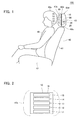
- Fig. 1 is a schematic diagram showing an example of a seat of a vehicle mounted with a headrest position adjusting device including a device for measuring the distance between a headrest and a head according to one embodiment of the present invention.
- Fig. 2 is an explanatory diagram showing an example of how the device for measuring the distance between the headrest and a head is disposed in the headrest according to one embodiment of the present invention.
- a headrest position adjusting device 100 is provided in a seat 40 of a vehicle, etc., and includes, for example, a distance measuring device 10 provided in a headrest front portion 43c constituting a part of a headrest 43 of the seat 40, and a drive motor unit 30 provided in a headrest back portion 43d constituting another part of the headrest 43.
- the distance measuring device 10 and the drive motor unit 30 are electrically connected to each other through, for example, a harness 29.
- the headrest front portion 43c is connected to the headrest back portion 43d through a support shaft 43b to be freely movable in the frontward-rearward direction of the vehicle.
- the headrest back portion 43d is connected to a backrest (a back seat) 41 of the seat 40 through a support shaft 43a to be freely movable in the upward-downward direction (the height direction of the headrest 43) and leftward-rightward direction of the vehicle.
- the distance measuring device 10 includes a plurality of sensing electrodes 11 to 15 formed on one surface (front surface) of a substrate 19, and a detecting circuit 20 formed (mounted) on the other surface (back surface) of the substrate 19.
- the distance measuring device 10 detects capacitance values based on capacitances from the sensing electrodes 11 to 15, detects a head 49a of a human body 49 sitting on a sitting portion 42 of the seat 40, and measures an electrode-head distance indicating the distance between the headrest front portion 43c and the head 49a.
- the substrate 19 is made of, for example, a flexible printed board, a rigid substrate, or a rigid flexible substrate.
- the plurality of sensing electrodes 11 to 15 are made of a conductive material such as copper, a copper alloy, aluminum, etc. which is patterned on the substrate 19 made of an insulating material such as polyethylene terephthalate (PET), polyethylene naphthalate (PEN), polyimide (PI), polyamide (PA), an epoxy resin, etc.
- PET polyethylene terephthalate
- PEN polyethylene naphthalate
- PI polyimide
- PA polyamide
- the plurality of sensing electrodes 11 to 15 may be made of a material such as an electric wire, a conductive film, etc.
- the plurality of sensing electrodes 11 to 15 are provided in the headrest front portion 43c at a portion close to the front surface thereof, formed in a rectangular strip shape having its longer dimension extend in the width direction (leftward-rightward direction) of the headrest 43 perpendicular to the height direction of the headrest 43, and arranged side by side with their widths lined up along the height direction of the headrest 43. Electrode numbers 1 to 5 (N1 to N5 or ch1 to ch5) are allocated to the plurality of sensing electrodes 11 to 15 respectively.
- the present example there are provided five electrodes, but it is only necessary to provide such a number of electrodes as are necessary for sensing a capacitance between the head 49a of the human body 49 sitting on the seat 40 and the headrest 43 while the headrest 43 is at rest. For example, it is enough if there are provided two or more electrodes.
- the distance measuring device 10 generates on a virtual calculation region, a two-dimensional coordinate system representing the positions of the plurality of sensing electrodes 11 to 15 on its one axis and detected capacitance values on its other axis, based on the capacitance values detected by the measurement. Then, on this two-dimensional coordinate system, the distance measuring device 10 generates a line AB which connects a point A (see Figs.6 ; the same applies hereinafter) representing the position and capacitance value of the sensing electrode (e.g., the sensing electrode 15) located at the highest position of the headrest front portion 43c among the plurality of sensing electrodes 11 to 15 and a point B (see Figs. 6 ; the same applies hereinafter) representing the position and capacitance value of the sensing electrode (e.g., the sensing electrode 13) having detected the largest capacitance value.
- a point A see Figs.6 ; the same applies hereinafter
- the sensing electrode e.g., the sensing
- the distance measuring device 10 generates a line CB which connects a point C (see Figs. 6 ; the same applies hereinafter) representing the position and capacitance value of the sensing electrode (e.g., the sensing electrode 11) located at the lowest position of the headrest front portion 43c and a point B representing the position and capacitance value of the sensing electrode (e.g., the sensing electrode 13) having detected the largest capacitance value.
- the distance measuring device 10 calculates an angle formed by the line AB and the line CB generated on the two-dimensional coordinate system as a distance calculation angle ⁇ (see Figs. 6 ; the same applies hereinafter), and measures the electrode-head distance based on the distance calculation angle ⁇ .
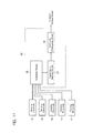
- the detecting circuit 20 of the distance measuring device 10 includes a plurality of capacitance sensing circuits 21 to 25 which are connected one-to-one to the sensing electrodes 11 to 15 and output information indicating the capacitances sensed by the sensing electrodes 11 to 15.
- the detecting circuit 20 also includes an arithmetic processing circuit 28 which is connected to the capacitance sensing circuits 21 to 15, calculates the distance calculation angle ⁇ and the electrode-head distance based on the capacitances indicated by the information output by the capacitance sensing circuits 21 to 15, calculates the height position of the head 49a by comparing the capacitances, and outputs information indicating the calculation results to a motor driving circuit (unillustrated) of the drive motor unit 30.
- the plurality of capacitance sensing circuits 21 to 15 generate pulse signals having duty ratios which change in accordance with the capacitances between the sensing electrodes 11 to 15 and the head 49a, smooth the pulse signals, and output them as sensing signals.
- the arithmetic processing circuit 28 includes, for example, a CPU, a RAM, a ROM, etc., calculates the distance calculation angle ⁇ and electrode-head distance described above by using capacitance values which are based on sensing signals from the capacitance sensing circuits 21 to 25, calculates, for example, the height position of the head 49a, and outputs a control signal, which is information based on the calculation results, to at least the drive motor unit 30 configured to change the position of the headrest front portion 43c.
- each capacitance sensing circuit 21 has a duty ratio which changes in accordance with a capacitance C, and for example, includes a trigger signal generating circuit 101 which outputs a trigger signal TG having a fixed period, a timer circuit 102 which outputs a pulse signal Po having a duty ratio which changes in accordance with the level of the capacitance C connected to an input terminal, and a low-pass filter (LPF) 103 which smoothes the pulse signal Po.
- a trigger signal generating circuit 101 which outputs a trigger signal TG having a fixed period
- a timer circuit 102 which outputs a pulse signal Po having a duty ratio which changes in accordance with the level of the capacitance C connected to an input terminal
- LPF low-pass filter
- the timer circuit 102 includes two comparators 201 and 202, an RS flip-flop circuit (hereinafter referred to as "RS-FF") 203 which receives the outputs of these comparators 201 and 202 at its reset terminal R and its set terminal S respectively, a buffer 204 which outputs an output DIS of the RS-FF 203 to the LPF 103, and a transistor 205 which is controlled between on and off according to the output DIS of the RS-FF 203.
- RS-FF RS flip-flop circuit
- the comparator 202 compares such a trigger signal TG as shown in Fig. 5 which is output from the trigger signal generating circuit 101 with a predetermined threshold Vth2 divided by resistors R1, R2, and R3, and outputs a set pulse synchronized with the trigger signal TG This set pulse sets the Q output of the RS-FF 203.
- the Q output as a discharge signal DIS turns off the transistor 205, and electrically charges between the sensing electrode 11 (12 to 15) and the ground (GND) at a speed defined by a time constant set by the to-ground capacitance C of the sensing electrode 11 (12 to 15) and a resistor R4 connected between the input terminal and a power supply line. Accordingly, the potential of an input signal Vin rises at a speed defined by the capacitance C.
- the output of the comparator 201 is inverted, thereby inverting the output of the RS-FF 203.
- the transistor 205 is turned on, and the charges accumulated in the sensing electrode 11 (12 to 15) are discharged through the transistor 205.
- the timer circuit 102 outputs a pulse signal Po which, as shown in Fig. 5 , oscillates at a duty ratio that is based on the capacitance C between the sensing electrode 11 (12 to 15) and the head 49a of the human body 49 coming close to the sensing electrode.
- the LPF 103 outputs a direct-current sensing signal Vout shown in Fig. 5 by smoothing the pulse signal Po.
- a waveform indicated by a solid line and a waveform indicated by a dotted line show that the former has a smaller capacitance than that of the latter, and, for example, the latter represents a condition that an object is coming close.
- the drive motor unit 30 includes a motor driving circuit which changes the position of the headrest 43 by controlling an unillustrated drive motor based on a control signal which is based on calculation results of the arithmetic processing circuit 28 which has performed calculations in the detecting circuit 20 of the distance measuring device 10 based on sensing signals Vout from the capacitance sensing circuits 21 to 25.
- the drive motor unit 30 also includes a drive motor which actually moves the position of the headrest 43 under the control of the motor driving circuit.
- the drive motor unit 30 adjusts at least the headrest front portion 43c by causing a movement (frontward-rearward movement) of the headrest front portion 43c in the frontward direction or rearward direction of the vehicle based on a measurement result of the distance measuring device 10. That is, by using the electrode-head distance included in the measurement result, the drive motor unit 30 causes a following movement of the headrest front portion 43c such that the headrest front portion 43c comes at a fixed distance from the head 49a.
- the drive motor is configured to drive the support shaft 43b of the headrest front portion 43c to freely move in the frontward-rearward direction and drive the support shaft 43a of the headrest back portion 43d to freely move in the upward-downward direction and the leftward-rightward direction (i.e., to make an upward-downward/leftward-rightward movement).
- the headrest position adjusting device 100 can adjust the headrest 43 to an appropriate position for the head 49a by causing not only a frontward-rearward movement of the headrest 43 described above but an upward-downward/leftward-rightward movement thereof.
- the headrest position adjusting device 100 configured as described above can perform position adjustment for the headrest 43 based on a measurement result which includes the distance (electrode-head distance) between the head 49a and the headrest 43 (headrest front portion 43c), which is obtained by the sensing electrodes 11 to 15 of the distance measuring device 10 sensing capacitances C with respect to the head 49a and the detecting circuit 20 calculating the distance calculation angle ⁇ , etc. based on the values of the capacitances.
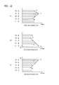
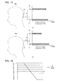
- Figs. 6 are explanatory diagrams showing examples of outputs of the sensing electrodes of the distance measuring device according to one embodiment of the present invention.
- Figs. 7 are diagrams explaining a relationship between the distance calculation angle and the electrode-head distance according to the distance measuring device.
- a value (capacitance value) to be output on a two-dimensional coordinate system D will be as follows.
- the output value of the sensing electrode 13 is the largest of the output values of the sensing electrodes 11 to 15 and the output values of the sensing electrodes 15 and 11 which are located at the highest position or the lowest position of the headrest front portion 43c are the smallest.
- the distance measuring device 10 generates on the two-dimensional coordinate system D, a line AB which connects a point A representing the position and output value of the sensing electrode 15 located at the highest position and a point B representing the position and output value of the sensing electrode 13 from which the largest output value is detected.
- the distance measuring device 10 also generates a line BC which connects a point C representing the position and output value of the sensing electrode 11 located at the lowest position and the point B representing the position and output value of the sensing electrode 13 from which the largest output value is detected.
- the distance measuring device 10 can obtain a distance calculation angle ⁇ determined by the two lines AB and CB and can derive an electrode-head distance L determined by the obtained distance calculation angle ⁇ by comparing the distance calculation angle ⁇ with such data as shown in Fig. 7 which profiles a relationship between distance and angle.
- the distance calculation angle ⁇ can also be obtained by calculating a first distance calculation angle ⁇ 1 formed by the line AB and a base line BL which extends from the point B to the axis representing the positions of the sensing electrodes perpendicularly to this axis and a second distance calculation angle ⁇ 2 formed by the base line BL and the line CB and combining these angles.
- the angles ⁇ 1 and ⁇ 2 can be calculated by the following formulae (1) and (2).
- the largest output value is the output value of the sensing electrode 11 as shown in Fig. 6(b) , given that the electrode-head distance L is equal to or less than a predetermined range and the vicinity of the sensing electrode 11 located at the lowest position and the center position P of the head 49a face each other substantially horizontally.
- a line BCCO which connects the zero point C0 of the output value of the sensing electrode 11 and the point (the point representing the largest output value) BC and a line ABC which connects this point BC and the point A representing the position and output value of the sensing electrode 15 located at the highest position form a distance calculation angle ⁇ (a first distance calculation angle ⁇ 1 or the slope of the line ABC (an acute angle) ⁇ 1).
- the largest output value is the output value of the sensing electrode 15 as shown in Fig. 6(c) , given that, for example, the electrode-head distance L is equal to or less than a predetermined range and the vicinity of the sensing electrode 15 located at the highest position and the center position P of the head 49a face each other substantially horizontally.
- a line ABA0 which connects the zero point A0 of the output value of the sensing electrode 15 and the point (the point representing the largest output value) AB and a line ABC which connects this point AB and the point C representing the position and output value of the sensing electrode 11 located at the lowest position form a distance calculation angle ⁇ (a second distance calculation angle ⁇ 2 or the slope of the line ABC (an acute angle) ⁇ 2).
- the first distance calculation angle ⁇ 1 or the second distance calculation angle ⁇ 2 which can be obtained in this way exhibits a relationship of becoming larger as the electrode-head distance L becomes larger, as represented by a correlation curve T1.
- the distance calculation angle ⁇ exhibits a relationship of becoming larger as the electrode-head distance L becomes larger, as represented by a correlation curve T2.
- the distance measuring device 10 can measure the electrode-head distance L by letting the arithmetic processing circuit 28 of the detecting circuit 20 use this distance calculation angle ⁇ (including the first and second distance calculation angles ⁇ 1 and ⁇ 2; the same applies hereinafter). Then, the headrest position adjusting device 100 including this distance measuring device 10 adjusts the position of the headrest 43 to an appropriate position for the head 49a based on the measurement result obtained by the distance measuring device 10.
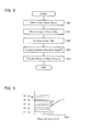
- Fig. 8 is a flowchart showing one example of the procedures of a distance measuring process by the method of measuring the distance between the headrest and the head according to one embodiment of the present invention.
- the distance measuring device 10 detects capacitance values which are based on capacitances sensed by the sensing electrodes 11 to 15 with respect to the head 49a (step S10).
- the distance measuring device 10 extracts the largest output value (peak output value) from among the detected capacitance values (step S11), and generates an output map by mapping the output values on such a two-dimensional coordinate system D as described above which represents the positions of the sensing electrodes 11 to 15 on its one axis and capacitance values on its other axis (step S12).
- the distance measuring device 10 calculates the distance calculation angle ⁇ in the way described above (step S13), and calculates the electrode-head distance L by, for example, comparing the calculated distance calculation angle ⁇ with data profiling a relationship between distance and angle (step S14) thereby to measure the actual distance between the headrest 43 and the head 49c.
- Fig. 9 is an explanatory diagram explaining a second example of outputs of the sensing electrodes of the distance measuring device according to one embodiment of the present invention.
- Figs. 10 are explanatory diagrams explaining third examples of outputs of the sensing electrode of the distance measuring device according to one embodiment of the present invention.
- the distance measuring device 10 may also obtain the distance calculation angle ⁇ in the following way, for example. That is, as shown in Fig.
- the distance measuring device 10 generates a line EF which connects a point E representing the position and output value of the sensing electrode 12 from which the smallest output value is detected among the plurality of sensing electrodes 11 to 15 and a point F representing the position and output value of the sensing electrode 14 from which the largest output value is detected.
- the distance measuring device 10 also generates a line FFO which connects the zero point F0 of the output value of the sensing electrode 14 and the point F to form a distance calculation angle ⁇ by the line EF and the line FFO, and measures the electrode-head distance L.
- the distance measuring device 10 can obtain the distance calculation angle ⁇ by calculating the angle of this slope.
- the distance measuring device 10 may generate a line JK which connects a point J representing the position and output value of the sensing electrode 14 from which the largest output value is detected and a point K representing the position and output value of the sensing electrode 15 from which the smallest output value is detected among the sensing electrodes located above the sensing electrode 14.
- the distance measuring device 10 may generate a line JM which connects the point J representing the sensing electrode 14 and a point M representing the position and output value of the sensing electrode 12 from which the smallest output value is detected among the sensing electrodes located under the sensing electrode 14 to form a distance calculation angle ⁇ by the line JK and the line JM and thereby measure the electrode-head distance L.
- the distance measuring device 10 may generate a line UV which connects a point U representing the position and output value of the sensing electrode 14 from which the smallest output value is detected and a point V representing the position and output value of the sensing electrode 11 from which the largest output value is detected.
- the distance measuring device 10 may also generate a line VV0 which connects the zero point V0 of the output value of the sensing electrode 11 and the point V to form a distance calculation angle ⁇ by the line UV and the line VVO and thereby measure the electrode-head distance L. Also in this case, since the distance calculation angle ⁇ is equal to the acute-angle slope of the line UV, the distance measuring device 10 can obtain the distance calculation angle ⁇ by calculating the angle of this slope.
- the distance measuring device 10 may generate a line RS which connects a point R representing the position and output value of the sensing electrode 12 from which the smallest output value is detected and a point S representing the position and output value of the sensing electrode 15 from which the largest output value is detected.
- the distance measuring device 10 may also generate a line SSO which connects the zero point S0 of the output value of the sensing electrode 15 and the point S to form a distance calculation angle ⁇ by the line RS and the line SSO and thereby measure the electrode-head distance L. Also in this case, since the distance calculation angle ⁇ is equal to the acute-angle slope of the line RS, the distance measuring device 10 can obtain the distance calculation angle ⁇ by calculating the angle of this slope.
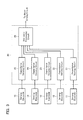
- Fig. 11 is a block diagram showing another example of the whole configuration of a device for measuring the distance between a headrest and a head according to one embodiment of the present invention.
- any portions that are the same as those already explained will be denoted by the same reference numerals and explanation thereof will not be provided.
- Fig. 11 is a block diagram showing another example of the whole configuration of a device for measuring the distance between a headrest and a head according to one embodiment of the present invention.
- the detecting circuit 20 includes a switching circuit 26 connected to the sensing electrodes 11 to 15, a capacitance sensing circuit 27 which outputs information indicating a capacitance sensed by any of the sensing electrodes 11 to 15 which are to be connected to the capacitance sensing circuit 27 intertemporally through the switching circuit 26, and an arithmetic processing circuit 28 which calculates a distance calculation angle ⁇ , an electrode-head distance L, etc. based on the information output by the capacitance sensing circuit 27 and outputs information indicating the calculation result to the motor driving circuit of the drive motor unit 30.
- This configuration of the detecting circuit 20 allows the distance measuring device 10 to be configured with a minimum number of capacitance sensing circuits, and enables the electrode-head distance L to be obtained by calculating the above-described distance calculation angle ⁇ based on a result of sequentially scanning the capacitances of the respective sensing electrodes 11 to 15 which are switched among them by the switching circuit 26.
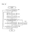
- Fig. 12 is a flowchart showing an example of the procedures of a position adjusting process by a headrest position adjusting method according to one embodiment of the present invention.
- the headrest position adjusting device 100 described above includes the distance measuring device 10 as part of its configuration
- the arithmetic processing circuit 28 of the detecting circuit 20 has a function as a control unit for controlling the entire headrest position adjusting device 100 and a function as distance measuring means and position adjusting means.
- a position adjusting process for adjusting the headrest 43 in the frontward-rearward direction will be explained.
- the headrest position adjusting device 100 judges whether or not the process is to be started as triggered by, for example, an ignition switch of the vehicle being turned to an accessory state or an ON state (step S100). When it is judged that the process is not to be started (step S100; N), the headrest position adjusting device 100 terminates the series of position adjusting process according to this flowchart.
- the headrest position adjusting device 100 When it is judged that the process is to be started (step S100; Y), the headrest position adjusting device 100 lets the distance measuring device 10 perform the distance measuring process described above (step S101), and obtains the measurement result (step S102). Then, the headrest position adjusting device 100 judges whether or not the distance calculation angle ⁇ included in the measurement result is equal to or larger than, for example, a predetermined angle shown in the above-described data profiling a relationship between distance and angle (step S103). Note that the predetermined angle may be preset to an angle which defines a distance that is the most preferable as the electrode-head distance L (i.e., the optimum distance to the head 49a).
- the headrest position adjusting device 100 calculates the difference between the electrode-head distance L defined by the distance calculation angle ⁇ and the distance defined by the predetermined angle, and controls the drive motor unit 30 to move the headrest front portion 43c frontward by an amount of the calculated difference (step S104).
- the headrest position adjusting device 100 calculates the difference likewise, and moves the headrest front portion 43c rearward by an amount of the calculated difference (step S105).
- the headrest position adjusting device 100 judges whether or not the process is to be terminated by, for example, the ignition switch of the vehicle being turned OFF (step S106), and when it is judged that the process is to be terminated (step S106; Y), terminates the series of position adjusting process according to the present flowchart.
- step S106; N the headrest position adjusting device 100 goes to step S101 described above and repeats the subsequent process.
- step S103 comparison is made between the distance calculation angle ⁇ and the predetermined angle.
- comparison may be made between the electrode-head distance L determined by the distance calculation angle ⁇ and the optimum distance described above to go on to step S104 or step S105 described above.
- Fig. 13 is a flowchart showing another example of the procedures of a position adjusting process by a headrest position adjusting method according to one embodiment of the present invention.
- a position adjusting process for adjusting the headrest 43 in the upward-downward direction will be explained.
- the process from step S110 to step S112 of the present flowchart is the same as the process from step S100 to step S102 described above, and hence explanation thereof will not be provided.
- the headrest position adjusting device 100 judges whether or not the distance calculation angle ⁇ included in the measurement result is larger than a predetermined threshold (for example, a predetermined angle shown in the above-described data profiling a relationship between distance and angle) (step S113).
- a predetermined threshold for example, a predetermined angle shown in the above-described data profiling a relationship between distance and angle
- the headrest position adjusting device 100 stops the position adjusting operation for the headrest back portion 43d in the height direction (step S114) and waits until a predetermined time passes (step S115; N).
- the headrest position adjusting device 100 calculates the height position of the head 49a by using the capacitance values included in the measurement result (step S117), and performs the position adjusting operation for the headrest back portion 43d in the height direction (step S118).
- the headrest position adjusting device 100 calculates the height position of the head 49a based on the capacitance values included in the measurement result obtained by all of the sensing electrodes 11 to 15 of the distance measuring device 10. For example, the headrest position adjusting device 100 calculates a position that is estimated to be the height-direction center of the head 49a (an estimated center position) by comparing these capacitance values, and calculates the height position of the head 49a based on this estimated center position.
- step S115; Y When the predetermined time has passed (step S115; Y) or when the position adjusting operation has been completed (step S118), the headrest position adjusting device 100 judges whether or not the process is to be terminated (step S116), and when it is judged that the process is to be terminated (step S116; Y), terminates the series of position adjusting process according to the present flowchart.
- step S116; N When it is judged that the process is not to be terminated (step S116; N), the headrest position adjusting device 100 goes to step S111 described above and repeats the subsequent process.
- the position adjusting process By performing the position adjusting process in this way, it is possible to perform position adjustment by using the measurement result obtained by the distance measuring device 10 and moving the headrest back portion 43d in the upward-downward direction.
- the position adjusting process stops the height-direction position adjusting operation for the headrest back portion 43d. This makes it possible to prevent an unnecessary movement of the headrest 43, avoid giving discomfort to the occupant (vehicle occupant) as much as possible, and suppress unnecessary power consumption.
- Fig. 14 is a flowchart showing still another example of the procedures of a position adjusting process by a headrest position adjusting method according to one embodiment of the present invention.
- the process from step S120 to step S123 of the present flowchart is the same as the process from step S110 to step S113 described above, and hence explanation thereof will not be provided.
- the headrest position adjusting device 100 can judge that the electrode-head distance L is greater than a predetermined range.
- a predetermined threshold for example, a predetermined angle shown in the above-described data profiling a relationship between distance and angle
- the headrest position adjusting device 100 compares the capacitance value of the sensing electrode located at the highest position (for example, the sensing electrode 15) and the capacitance value of the sensing electrode located at the lowest position (for example, the sensing electrode 11) based on the measurement result (step S124) to calculate the height position of the head 49a.
- the headrest position adjusting device 100 can judge that the electrode-head distance L is equal to or less than the predetermined range.
- the headrest position adjusting device 100 compares the capacitance values of all of the sensing electrodes 11 to 15 based on the measurement result to calculate the height position of the head 49a (step S125). After this, the headrest position adjusting device 100 performs a height-direction position adjusting operation for the headrest back portion 43d based on the calculation result of step S124 or step S125 (step S126).
- the headrest position adjusting device 100 judges whether or not the process is to be terminated (step S127).
- the headrest position adjusting device 100 terminates the series of position adjusting process according to the present flowchart when it is judged that the process is to be terminated (step S127; Y), or goes to step S121 described above and repeats the subsequent process when it is judged that the process is not to be terminated (step S127; N).
- An amount (mm) to move the headrest (H/R) can be calculated based on the obtained output ratio ⁇ .
- a control signal is output to the drive motor unit 30 to move the headrest back portion 43d upward (in a "+” direction) when the output ratio ⁇ is close to 0, or to move the headrest back portion 43d downward (in a "-" direction) when the output ratio ⁇ is close to 1.
- the headrest position adjusting device 100 can obtain the position of the head 49a through the step S124 described above based on the capacitance values of the sensing electrodes 15 and 11 located at the highest and lowest positions when the distance calculation angle ⁇ is larger than the predetermined threshold and hence the electrode-head distance L is greater than the predetermined range, or through step S125 described above based on the capacitance values of the sensing electrodes 11 to 15 when the distance calculation angle ⁇ is equal to or smaller than the predetermined threshold and hence the electrode-head distance L is equal to or less than the predetermined range. Therefore, the headrest position adjusting device 100 can adjust the position of the headrest 43 highly accurately with a simple configuration, and can prevent accidents due to failure to adjust the position of the headrest 43, such as cervical spine injury of the human body 49 in a car crash, etc.
- comparison is made between the distance calculation angle ⁇ and the predetermined threshold.
- comparison may be made between the electrode-head distance L determined by the distance calculation angle ⁇ and the optimum distance described above to perform the subsequent process.
- position adjustment is performed by moving the headrest front portion 43c or the headrest back portion 43d in the frontward-rearward direction or in the upward-downward direction through the position adjusting processes shown in Figs. 12 to 14 .
- position adjustment may be performed by, for example, executing these processes in parallel based on the measurement result obtained from the distance measuring device 10, such that the position of the headrest 43 may be adjusted to a position that is appropriate for the head 49a in all of the frontward-rearward, upward-downward, and leftward-rightward directions.
- the distance measuring device 10 may measure the electrode-head distance L by letting the arithmetic processing circuit 28 select a preset slope coefficient for the distance calculation angle ⁇ based on the sensing electrode from which the largest output value is measured when capacitance values are measured from the sensing electrodes 11 to 15 and make a comparison based on the slope coefficient.
- the distance measuring device 10 may include, for example, three sensing electrodes which are located at the highest position, the lowest position, and the middle position between these positions of the headrest front portion 43c, and measure the electrode-head distance L by calculating the distance calculation angle ⁇ based on the capacitance values of these sensing electrodes.
Landscapes
- Engineering & Computer Science (AREA)
- Aviation & Aerospace Engineering (AREA)
- Transportation (AREA)
- Mechanical Engineering (AREA)
- Physics & Mathematics (AREA)
- General Physics & Mathematics (AREA)
- Seats For Vehicles (AREA)
- Chair Legs, Seat Parts, And Backrests (AREA)
- Measurement Of Length, Angles, Or The Like Using Electric Or Magnetic Means (AREA)
Abstract
Description
- The present invention relates to a device for measuring the distance between a headrest and a head for measuring and utilizing the distance between a headrest provided on a seat of a vehicle such as an automobile and a head, a method for measuring the distance between a headrest and a head, a headrest position adjusting device, and a headrest position adjusting method.
- Conventionally, a vehicle headrest device (for example, see Patent Document 1 (pp.6-8, and
Figs. 1-4 )) is known as a technique for adjusting the position of a headrest provided on a seat of a vehicle such as an automobile, etc. When this vehicle headrest device moves the front portion of the headrest in a direction to be fully opened, an ECU of the device judges based on a detection result of a capacitance sensor that the front portion of the headrest has come close to the head of a vehicle occupant and stops the front portion of the headrest. - The ECU judges that the front portion of the headrest has come close to the head of the vehicle occupant based on an absolute capacitance change from a reference capacitance value of the capacitance sensor or based on an amount of change of the capacitance value.
- A vehicle occupant protecting device (for example, see Patent Document 2 (pp. 3-6, and
Figs. 1-5 )) is a technique for moving a headrest, which is movable forward with respect to the vehicle, to a pre-crash phase before an object crashes into the vehicle from behind. This device controls the amount to move the headrest frontward based on how a capacitance sensed by a capacitance sensor changes. - A vehicle occupant sensing system (for example, see Patent Document 3 (pp. 3-5, and
Figs. 1-4 )) generates a weak electric field around a plurality of strip-shaped antenna electrodes which are provided in a horizontal state in a backrest (or a seat back) of a seat with a gap provided therebetween in the vertical direction. The system detects a current flowing through the antenna electrodes based on the weak electric field. - Then, the system extracts the shoulder line of the vehicle occupant sitting on the seat based on the detected current, senses the position of the head based on the shoulder line, and sends data based on the sensing result to an air bag device. In this way, the system sets the air bag of the air bag device to a deployable or non-deployable state.
-
- Patent Document 1:
JP No. 4018112 - Patent Document 2:
JP2007-131026A - Patent Document 3:
JP No. 3347069 - However, the vehicle headrest device disclosed in
Patent Document 1 identified above and the vehicle occupant protecting device disclosed inPatent Document 2 identified above have to move the headrest constantly in order to determine the distance between the head of the vehicle occupant and the headrest. Moreover, if the head of the vehicle occupant moves while the headrest is operating, the device might detect a false amount of movement. This takes unnecessary power consumption, generates an error in a calculation result, and makes it difficult to move the headrest with a correct distance determination. - Furthermore, since the vehicle occupant sensing system disclosed in Patent Document 3 identified above is a system for sensing the physical constitution of the vehicle occupant, it cannot be applied to, for example, a system for maintaining the distance between the headrest and the head of the vehicle occupant.
- To solve the problems of the conventional techniques described above, an object of the present invention is to provide a device for measuring the distance between a headrest and a head, a method for measuring the distance between a headrest and a head, a headrest position adjusting device, and a headrest position adjusting method which are, with a simple configuration, capable of measuring the distance between a headrest and a head and automatically adjusting the position of the headrest accurately by, in particular, preventing an unnecessary movement of the headrest.
- To solve the problems described above and achieve the object, a device for measuring a distance between a headrest and a head according to the present invention includes: a plurality of sensing electrodes which are provided in a headrest provided on a seat of a vehicle for sensing capacitances between a head of a human body sitting on the seat and the headrest, the sensing electrodes being provided side by side along a height direction of the headrest; a detecting circuit which detects capacitance values which are based on the capacitances from the plurality of sensing electrodes; and distance measuring means which measures an electrode-head distance indicating a distance between the headrest and the head, in accordance with detection results detected by the detecting circuit, wherein when the sensing electrode located at a highest position of the headrest or the sensing electrode located at a lowest position thereof among the plurality of sensing electrodes does not show a largest capacitance, the distance measuring means measures the electrode-head distance by calculating, on a two-dimensional coordinate system representing positions of the plurality of sensing electrodes on its one axis and the capacitance values detected by the detecting circuit on its other axis, a distance calculation angle formed by a line which connects a point representing the position and capacitance value of the sensing electrode located at the highest position of the headrest and a point representing the position and capacitance value of the sensing electrode from which a largest capacitance value is detected and a line which connects a point representing the position and capacitance value of the sensing electrode located at the lowest position of the headrest and the point representing the position and capacitance value of the sensing electrode from which the largest capacitance value is detected, and when the sensing electrode located at the highest position of the headrest or the sensing electrode located at the lowest position thereof shows the largest capacitance, the distance measuring means measures the electrode-head distance by calculating, on the two-dimensional coordinate system, an angle of a slope of a line which connects the point representing the position and capacitance value of the sensing electrode located at the highest position of the headrest and the point representing the position and capacitance value of the sensing electrode located at the lowest position of the headrest.
- A device for measuring a distance between a headrest and a head according to the present invention includes: a plurality of sensing electrodes which are provided in a headrest provided on a seat of a vehicle for sensing capacitances between a head of a human body sitting on the seat and the headrest, the sensing electrodes being provided side by side along a height direction of the headrest; a detecting circuit which detects capacitance values which are based on the capacitances from the plurality of sensing electrodes; and distance measuring means which measures an electrode-head distance indicating a distance between the headrest and the head, in accordance with detection results detected by the detecting circuit, wherein the distance measuring means measures the electrode-head distance by calculating, on a two-dimensional coordinate system representing positions of the plurality of sensing electrodes on its one axis and the capacitance values detected by the detecting circuit on its other axis, an angle of a slope of a line which connects a point representing the position and capacitance value of the sensing electrode from which a smallest capacitance value is detected among the plurality of sensing electrodes and a point representing the position and capacitance value of the sensing electrode from which a largest capacitance value is detected among the plurality of sensing electrodes.
- A device for measuring a distance between a headrest and a head according to the present invention includes: a plurality of sensing electrodes which are provided in a headrest provided on a seat of a vehicle for sensing capacitances between a head of a human body sitting on the seat and the headrest, the sensing electrodes being provided side by side along a height direction of the headrest; a detecting circuit which detects capacitance values which are based on the capacitances from the plurality of sensing electrodes; and distance measuring means which measures an electrode-head distance indicating a distance between the headrest and the head, in accordance with detection results detected by the detecting circuit, wherein when the sensing electrode located at a highest position of the headrest or the sensing electrode located at a lowest position thereof among the plurality of sensing electrodes does not show a largest capacitance, the distance measuring means measures the electrode-head distance by calculating, on a two-dimensional coordinate system representing positions of the plurality of sensing electrodes on its one axis and the capacitance values detected by the detecting circuit on its other axis, a distance calculation angle formed by a line which connects a point representing the position and capacitance value of the sensing electrode from which a largest capacitance value is detected and a point representing the position and capacitance value of the sensing electrode from which a smallest capacitance value is detected among the sensing electrodes located above the sensing electrode from which the largest capacitance value is detected and a line which connects the point representing the position and capacitance value of the sensing electrode from which the largest capacitance value is detected and a point representing the position and capacitance value of the sensing electrode from which a smallest capacitance value is detected among the sensing electrodes located under the sensing electrode from which the largest capacitance value is detected, and when the sensing electrode located at the highest position of the headrest or the sensing electrode located at the lowest position thereof shows the largest capacitance, the distance measuring means measures the electrode-head distance by calculating, on the two-dimensional coordinate system, an angle of a slope of a line which connects a point representing the position and capacitance value of the sensing electrode from which a smallest capacitance value is detected and a point representing the position and capacitance value of the sensing electrode from which a largest capacitance value is detected.
- For example, the distance measuring means may obtain a first distance calculation angle formed by the line which connects the point representing the sensing electrode located at the highest position and the point representing the sensing electrode from which the largest capacitance value is detected and a base line which extends to the one axis perpendicularly to the one axis from the point representing the sensing electrode from which the largest capacitance value is detected and a second distance calculation angle formed by the line which connects the point representing the sensing electrode located at the lowest position and the point representing the sensing electrode from which the largest capacitance value is detected and the base line, and may calculate the distance calculation angle based on these first and second distance calculation angles.
- For example, the distance measuring means may measure the electrode-head distance by comparing the distance calculation angle with preset data which profiles a relationship between distance and angle.
- For example, the plurality of sensing electrodes may be provided in the headrest at a portion closer to a front surface of the headrest and formed in a rectangular strip shape having its longer dimension extend in a width direction perpendicular to the height direction, and the detecting circuit may include a plurality of capacitance sensing circuits which are connected one-to-one to the plurality of sensing electrodes, and output the capacitance values which are based on the capacitances sensed by the sensing electrodes.
- For example, the plurality of sensing electrodes may be provided in the headrest at a portion closer to a front surface of the headrest and formed in a rectangular strip shape having its longer dimension extend in a width direction perpendicular to the height direction, and the detecting circuit may include a switching circuit connected to the plurality of sensing electrodes, and a capacitance sensing circuit which outputs the capacitance value which is based on the capacitance sensed by any of the sensing electrodes which are to be connected to the capacitance sensing circuit intertemporally through the switching circuit.
- A headrest position adjusting device according to the present invention includes: the device for measuring a distance between a headrest and a head according to any of the inventions described above; and position adjusting means which adjusts a position of the headrest to an appropriate position for the head based on a measurement result from the device for measuring a distance.
- For example, the position adjusting means may adjust the position of the headrest by moving the headrest in a frontward direction or rearward direction of the vehicle based on the distance calculation angle which is included in the measurement result, such that the distance calculation angle becomes a predetermined angle.
- For example, the position adjusting means may compare the distance calculation angle included in the measurement result with a predetermined threshold, and when the distance calculation angle is larger than the predetermined threshold, may stop a position adjusting operation for the headrest at least in the height direction.
- For example, when the position adjusting means stops the position adjusting operation for the headrest for a predetermined time, after the predetermined time passes, the position adjusting means may again compare the distance calculation angle with the predetermined threshold.
- For example, when the distance calculation angle included in the measurement result is larger than a predetermined threshold, the position adjusting means may adjust the position of the headrest by moving the headrest in an upward direction or downward direction of the vehicle by using the capacitance values which are detected by the detecting circuit based on the capacitances from at least the sensing electrode located at the highest position and the sensing electrode located at the lowest position among the plurality of sensing electrodes.
- When the distance calculation angle included in the measurement result is equal to or smaller than a predetermined threshold, the position adjusting means may calculate an appropriate position of the headrest with respect to the head by using the capacitance values which are detected by the detecting circuit based on the capacitances from the plurality of sensing electrodes, and may adjust the position of the headrest to the appropriate position.
- A method for measuring a distance between a headrest and a head according to the present invention includes: a sensing step of sensing capacitances between a head of a human body sitting on a seat of a vehicle and a headrest provided on the seat by means of a plurality of sensing electrodes which are provided in the headrest side by side along a height direction of the headrest; a detecting step of detecting capacitance values which are based on the capacitances sensed in the sensing step; and a distance measuring step of measuring an electrode-head distance indicating a distance between the headrest and the head, in accordance with detection results detected in the detecting step, wherein when the sensing electrode located at a highest position of the headrest or the sensing electrode located at a lowest position thereof among the plurality of sensing electrodes does not show a largest capacitance, the distance measuring step measures the electrode-head distance by calculating, on a two-dimensional coordinate system representing positions of the plurality of sensing electrodes on its one axis and the capacitance values detected in the detecting step on its other axis, a distance calculation angle formed by a line which connects a point representing the position and capacitance value of the sensing electrode located at the highest position of the headrest and a point representing the position and capacitance value of the sensing electrode from which a largest capacitance value is detected and a line which connects a point representing the position and capacitance value of the sensing electrode located at the lowest position of the headrest and the point representing the position and capacitance value of the sensing electrode from which the largest capacitance value is detected, and when the sensing electrode located at the highest position of the headrest or the sensing electrode located at the lowest position thereof shows the largest capacitance, the distance measuring step measures the electrode-head distance by calculating, on the two-dimensional coordinate system, an angle of a slope of a line which connects the point representing the position and capacitance value of the sensing electrode located at the highest position of the headrest and the point representing the position and capacitance value of the sensing electrode located at the lowest position of the headrest.
- A method for measuring a distance between a headrest and a head according to the present invention includes: a sensing step of sensing capacitances between a head of a human body sitting on a seat of a vehicle and a headrest provided on the seat by means of a plurality of sensing electrodes which are provided in the headrest side by side along a height direction of the headrest; a detecting step of detecting capacitance values which are based on the capacitances sensed in the sensing step; and a distance measuring step of measuring an electrode-head distance indicating a distance between the headrest and the head, in accordance with detection results detected in the detecting step, wherein the distance measuring step measures the electrode-head distance by calculating, on a two-dimensional coordinate system representing positions of the plurality of sensing electrodes on its one axis and the capacitance values detected in the detecting step on its other axis, an angle of a slope of a line which connects a point representing the position and capacitance value of the sensing electrode from which a smallest capacitance value is detected among the plurality of sensing electrodes and a point representing the position and capacitance value of the sensing electrode from which a largest capacitance value is detected among the plurality of sensing electrodes.
- A method for measuring a distance between a headrest and a head according to the present invention includes: a sensing step of sensing capacitances between a head of a human body sitting on a seat of a vehicle and a headrest provided on the seat by means of a plurality of sensing electrodes which are provided in the headrest side by side along a height direction of the headrest; a detecting step of detecting capacitance values which are based on the capacitances sensed in the sensing step; and a distance measuring step of measuring an electrode-head distance indicating a distance between the headrest and the head, in accordance with detection results detected in the detecting step, wherein when the sensing electrode located at a highest position of the headrest or the sensing electrode located at a lowest position thereof among the plurality of sensing electrodes does not show a largest capacitance, the distance measuring step measures the electrode-head distance by calculating, on a two-dimensional coordinate system representing positions of the plurality of sensing electrodes on its one axis and the capacitance values detected in the detecting step on its other axis, a distance calculation angle formed by a line which connects a point representing the position and capacitance value of the sensing electrode from which a largest capacitance value is detected and a point representing the position and capacitance value of the sensing electrode from which a smallest capacitance value is detected among the sensing electrodes located above the sensing electrode from which the largest capacitance value is detected and a line which connects the point representing the position and capacitance value of the sensing electrode from which the largest capacitance value is detected and a point representing the position and capacitance value of the sensing electrode from which a smallest capacitance value is detected among the sensing electrodes located under the sensing electrode from which the largest capacitance value is detected, and when the sensing electrode located at the highest position of the headrest or the sensing electrode located at the lowest position thereof shows the largest capacitance, the distance measuring step measures the electrode-head distance by calculating, on the two-dimensional coordinate system, an angle of a slope of a line which connects a point representing the position and capacitance value of the sensing electrode from which a smallest capacitance value is detected and a point representing the position and capacitance value of the sensing electrode from which a largest capacitance value is detected.
- For example, the distance measuring step may obtain a first distance calculation angle formed by the line which connects the point representing the sensing electrode located at the highest position and the point representing the sensing electrode from which the largest capacitance value is detected and a base line which extends to the one axis perpendicularly to the one axis from the point representing the sensing electrode from which the largest capacitance value is detected and a second distance calculation angle formed by the line which connects the point representing the sensing electrode located at the lowest position and the point representing the sensing electrode from which the largest capacitance value is detected and the base line, and may calculate the distance calculation angle based on these first and second distance calculation angles.
- For example, the distance measuring step may measure the electrode-head distance by comparing the distance calculation angle with preset data which profiles a relationship between distance and angle.
- A headrest position adjusting method according to the present invention includes: the method for measuring a distance between a headrest and a head according to any of the inventions described above; and a position adjusting step of adjusting a position of the headrest to an appropriate position for the head based on a measurement result measured by the method for measuring a distance.
- For example, the position adjusting step adjusts the position of the headrest by moving the headrest in a frontward direction or rearward direction of the vehicle based on the distance calculation angle which is included in the measurement result, such that the distance calculation angle becomes a predetermined angle.
- For example, the position adjusting step may compare the distance calculation angle included in the measurement result with a predetermined threshold, and when the distance calculation angle is larger than the predetermined threshold, may stop a position adjusting operation for the headrest at least in the height direction.
- For example, when the position adjusting step stops the position adjusting operation for the headrest for a predetermined time, after the predetermined time passes, the position adjusting step may again compare the distance calculation angle with the predetermined threshold.
- For example, when the distance calculation angle included in the measurement result is larger than a predetermined threshold, the position adjusting step may adjust the position of the headrest by moving the headrest in an upward direction or downward direction of the vehicle by using the capacitance values which are detected in the detecting step based on the capacitances from at least the sensing electrode located at the highest position and the sensing electrode located at the lowest position among the plurality of sensing electrodes.
- For example, when the distance calculation angle included in the measurement result is equal to or smaller than a predetermined threshold, the position adjusting step may calculate an appropriate position of the headrest with respect to the head by using the capacitance values which are detected in the detecting step based on the capacitances from the plurality of sensing electrodes, and may adjust the position of the headrest to the appropriate position.
- According to the present invention, it is possible to measure the distance between a headrest and a head with a simple configuration and automatically adjust the position of the headrest accurately by preventing an unnecessary movement of the headrest.
-
- [
Fig. 1] Fig. 1 is a schematic diagram showing an example of a seat of a vehicle mounted with a headrest position adjusting device including a device for measuring the distance between a headrest and a head according to one embodiment of the present invention. - [
Fig. 2] Fig. 2 is an explanatory diagram showing an example of how the device for measuring the distance between the headrest and a head is disposed in the headrest according to one embodiment of the present invention. - [
Fig. 3] Fig. 3 is a block diagram showing an example of the whole configuration of the distance measuring device. - [
Fig. 4] Fig. 4 is a block diagram showing an example of configuration of a capacitance sensing circuit of the distance measuring device. - [
Fig. 5] Fig. 5 is an operation waveform chart showing examples of operation waveforms of a detecting circuit of the distance measuring device. - [
Figs. 6] Figs. 6 are explanatory diagrams showing examples of outputs of sensing electrodes of a distance measuring device according to one embodiment of the present invention. - [
Figs. 7] Figs. 7 are explanatory diagrams explaining a relationship between a distance calculation angle and an electrode-head distance according to the distance measuring device. - [
Fig. 8] Fig. 8 is a flowchart showing one example of the procedures of a distance measuring process by a method of measuring the distance between a headrest and a head according to one embodiment of the present invention. - [
Fig. 9] Fig. 9 is an explanatory diagram explaining a second example of outputs of sensing electrodes of a distance measuring device according to one embodiment of the present invention. - [
Figs. 10] Figs. 10 are explanatory diagrams explaining third examples of outputs of sensing electrodes of a distance measuring device according to one embodiment of the present invention. - [
Fig. 11] Fig. 11 is a block diagram showing another example of the whole configuration of a device for measuring the distance between a headrest and a head according to one embodiment of the present invention. - [
Fig. 12] Fig. 12 is a flowchart showing an example of the procedures of a position adjusting process by a headrest position adjusting method according to one embodiment of the present invention. - [
Fig. 13] Fig. 13 is a flowchart for explaining another example of the procedures of a position adjusting process by a headrest position adjusting method according to one embodiment of the present invention. - [
Fig. 14] Fig. 14 is a flowchart showing still another example of the procedures of a position adjusting process by a headrest position adjusting method according to one embodiment of the present invention. - [
Figs. 15] Figs. 15 are explanatory diagrams showing examples of outputs of sensing electrodes of a headrest position adjusting device according to one embodiment of the present invention. - [
Fig. 16] Fig. 16 is an explanatory diagram explaining a relationship between an amount to move a headrest and a ratio of an amount of change of output according to the headrest position adjusting device. - Preferred embodiments of a device for measuring the distance between a headrest and a head, a method for measuring the distance between a headrest and a head, a headrest position adjusting device, and a headrest position adjusting method according to the present invention will now be explained below with reference to the attached drawings.
-
Fig. 1 is a schematic diagram showing an example of a seat of a vehicle mounted with a headrest position adjusting device including a device for measuring the distance between a headrest and a head according to one embodiment of the present invention.Fig. 2 is an explanatory diagram showing an example of how the device for measuring the distance between the headrest and a head is disposed in the headrest according to one embodiment of the present invention. - As shown in
Fig. 1 and Fig. 2 , a headrestposition adjusting device 100 is provided in aseat 40 of a vehicle, etc., and includes, for example, adistance measuring device 10 provided in aheadrest front portion 43c constituting a part of aheadrest 43 of theseat 40, and adrive motor unit 30 provided in a headrest backportion 43d constituting another part of theheadrest 43. Thedistance measuring device 10 and thedrive motor unit 30 are electrically connected to each other through, for example, aharness 29. - The
headrest front portion 43c is connected to the headrest backportion 43d through asupport shaft 43b to be freely movable in the frontward-rearward direction of the vehicle. The headrest backportion 43d is connected to a backrest (a back seat) 41 of theseat 40 through asupport shaft 43a to be freely movable in the upward-downward direction (the height direction of the headrest 43) and leftward-rightward direction of the vehicle. - For example, the
distance measuring device 10 includes a plurality ofsensing electrodes 11 to 15 formed on one surface (front surface) of asubstrate 19, and a detectingcircuit 20 formed (mounted) on the other surface (back surface) of thesubstrate 19. Thedistance measuring device 10 detects capacitance values based on capacitances from thesensing electrodes 11 to 15, detects ahead 49a of ahuman body 49 sitting on a sittingportion 42 of theseat 40, and measures an electrode-head distance indicating the distance between theheadrest front portion 43c and thehead 49a. - The
substrate 19 is made of, for example, a flexible printed board, a rigid substrate, or a rigid flexible substrate. The plurality ofsensing electrodes 11 to 15 are made of a conductive material such as copper, a copper alloy, aluminum, etc. which is patterned on thesubstrate 19 made of an insulating material such as polyethylene terephthalate (PET), polyethylene naphthalate (PEN), polyimide (PI), polyamide (PA), an epoxy resin, etc. Other than this, the plurality ofsensing electrodes 11 to 15 may be made of a material such as an electric wire, a conductive film, etc. - The plurality of
sensing electrodes 11 to 15 are provided in theheadrest front portion 43c at a portion close to the front surface thereof, formed in a rectangular strip shape having its longer dimension extend in the width direction (leftward-rightward direction) of theheadrest 43 perpendicular to the height direction of theheadrest 43, and arranged side by side with their widths lined up along the height direction of theheadrest 43.Electrode numbers 1 to 5 (N1 to N5 or ch1 to ch5) are allocated to the plurality ofsensing electrodes 11 to 15 respectively. In the present example, there are provided five electrodes, but it is only necessary to provide such a number of electrodes as are necessary for sensing a capacitance between thehead 49a of thehuman body 49 sitting on theseat 40 and theheadrest 43 while theheadrest 43 is at rest. For example, it is enough if there are provided two or more electrodes. - As will be described in detail later, the
distance measuring device 10 generates on a virtual calculation region, a two-dimensional coordinate system representing the positions of the plurality ofsensing electrodes 11 to 15 on its one axis and detected capacitance values on its other axis, based on the capacitance values detected by the measurement. Then, on this two-dimensional coordinate system, thedistance measuring device 10 generates a line AB which connects a point A (seeFigs.6 ; the same applies hereinafter) representing the position and capacitance value of the sensing electrode (e.g., the sensing electrode 15) located at the highest position of theheadrest front portion 43c among the plurality ofsensing electrodes 11 to 15 and a point B (seeFigs. 6 ; the same applies hereinafter) representing the position and capacitance value of the sensing electrode (e.g., the sensing electrode 13) having detected the largest capacitance value. - The
distance measuring device 10 generates a line CB which connects a point C (seeFigs. 6 ; the same applies hereinafter) representing the position and capacitance value of the sensing electrode (e.g., the sensing electrode 11) located at the lowest position of theheadrest front portion 43c and a point B representing the position and capacitance value of the sensing electrode (e.g., the sensing electrode 13) having detected the largest capacitance value. Thedistance measuring device 10 calculates an angle formed by the line AB and the line CB generated on the two-dimensional coordinate system as a distance calculation angle θ (seeFigs. 6 ; the same applies hereinafter), and measures the electrode-head distance based on the distance calculation angle θ. - As shown in
Fig. 3 , the detectingcircuit 20 of thedistance measuring device 10 includes a plurality ofcapacitance sensing circuits 21 to 25 which are connected one-to-one to thesensing electrodes 11 to 15 and output information indicating the capacitances sensed by thesensing electrodes 11 to 15. The detectingcircuit 20 also includes anarithmetic processing circuit 28 which is connected to thecapacitance sensing circuits 21 to 15, calculates the distance calculation angle θ and the electrode-head distance based on the capacitances indicated by the information output by thecapacitance sensing circuits 21 to 15, calculates the height position of thehead 49a by comparing the capacitances, and outputs information indicating the calculation results to a motor driving circuit (unillustrated) of thedrive motor unit 30. - The plurality of
capacitance sensing circuits 21 to 15 generate pulse signals having duty ratios which change in accordance with the capacitances between thesensing electrodes 11 to 15 and thehead 49a, smooth the pulse signals, and output them as sensing signals. Thearithmetic processing circuit 28 includes, for example, a CPU, a RAM, a ROM, etc., calculates the distance calculation angle θ and electrode-head distance described above by using capacitance values which are based on sensing signals from thecapacitance sensing circuits 21 to 25, calculates, for example, the height position of thehead 49a, and outputs a control signal, which is information based on the calculation results, to at least thedrive motor unit 30 configured to change the position of theheadrest front portion 43c. - Here, as shown in
Fig. 4 , for example, each capacitance sensing circuit 21 (22 to 25) has a duty ratio which changes in accordance with a capacitance C, and for example, includes a triggersignal generating circuit 101 which outputs a trigger signal TG having a fixed period, atimer circuit 102 which outputs a pulse signal Po having a duty ratio which changes in accordance with the level of the capacitance C connected to an input terminal, and a low-pass filter (LPF) 103 which smoothes the pulse signal Po. - For example, the
timer circuit 102 includes twocomparators comparators buffer 204 which outputs an output DIS of the RS-FF 203 to theLPF 103, and atransistor 205 which is controlled between on and off according to the output DIS of the RS-FF 203. - The
comparator 202 compares such a trigger signal TG as shown inFig. 5 which is output from the triggersignal generating circuit 101 with a predetermined threshold Vth2 divided by resistors R1, R2, and R3, and outputs a set pulse synchronized with the trigger signal TG This set pulse sets the Q output of the RS-FF 203. - The Q output as a discharge signal DIS turns off the
transistor 205, and electrically charges between the sensing electrode 11 (12 to 15) and the ground (GND) at a speed defined by a time constant set by the to-ground capacitance C of the sensing electrode 11 (12 to 15) and a resistor R4 connected between the input terminal and a power supply line. Accordingly, the potential of an input signal Vin rises at a speed defined by the capacitance C. - When the input signal Vin exceeds a threshold Vth1 defined by the resistors R1, R2, and R3, the output of the
comparator 201 is inverted, thereby inverting the output of the RS-FF 203. As a result, thetransistor 205 is turned on, and the charges accumulated in the sensing electrode 11 (12 to 15) are discharged through thetransistor 205. - Hence, the
timer circuit 102 outputs a pulse signal Po which, as shown inFig. 5 , oscillates at a duty ratio that is based on the capacitance C between the sensing electrode 11 (12 to 15) and thehead 49a of thehuman body 49 coming close to the sensing electrode. TheLPF 103 outputs a direct-current sensing signal Vout shown inFig. 5 by smoothing the pulse signal Po. InFig. 5 , a waveform indicated by a solid line and a waveform indicated by a dotted line show that the former has a smaller capacitance than that of the latter, and, for example, the latter represents a condition that an object is coming close. - The
drive motor unit 30 includes a motor driving circuit which changes the position of theheadrest 43 by controlling an unillustrated drive motor based on a control signal which is based on calculation results of thearithmetic processing circuit 28 which has performed calculations in the detectingcircuit 20 of thedistance measuring device 10 based on sensing signals Vout from thecapacitance sensing circuits 21 to 25. Thedrive motor unit 30 also includes a drive motor which actually moves the position of theheadrest 43 under the control of the motor driving circuit. - In the present example, the
drive motor unit 30 adjusts at least theheadrest front portion 43c by causing a movement (frontward-rearward movement) of theheadrest front portion 43c in the frontward direction or rearward direction of the vehicle based on a measurement result of thedistance measuring device 10. That is, by using the electrode-head distance included in the measurement result, thedrive motor unit 30 causes a following movement of theheadrest front portion 43c such that theheadrest front portion 43c comes at a fixed distance from thehead 49a. - Specifically, the drive motor is configured to drive the
support shaft 43b of theheadrest front portion 43c to freely move in the frontward-rearward direction and drive thesupport shaft 43a of the headrest backportion 43d to freely move in the upward-downward direction and the leftward-rightward direction (i.e., to make an upward-downward/leftward-rightward movement). Hence, the headrestposition adjusting device 100 according to the present example can adjust theheadrest 43 to an appropriate position for thehead 49a by causing not only a frontward-rearward movement of theheadrest 43 described above but an upward-downward/leftward-rightward movement thereof. - The headrest
position adjusting device 100 configured as described above can perform position adjustment for theheadrest 43 based on a measurement result which includes the distance (electrode-head distance) between thehead 49a and the headrest 43 (headrest front portion 43c), which is obtained by thesensing electrodes 11 to 15 of thedistance measuring device 10 sensing capacitances C with respect to thehead 49a and the detectingcircuit 20 calculating the distance calculation angle θ, etc. based on the values of the capacitances. -
Figs. 6 are explanatory diagrams showing examples of outputs of the sensing electrodes of the distance measuring device according to one embodiment of the present invention.Figs. 7 are diagrams explaining a relationship between the distance calculation angle and the electrode-head distance according to the distance measuring device. For example, as shown inFig. 6(a) , when the height-direction center position of thehead 49a is defined as P and a to-electrode distance from this center position P, which exists within an electrode-electrode distance H, to each of thesensing electrodes 11 to 15 is defined as L, a value (capacitance value) to be output on a two-dimensional coordinate system D will be as follows. - That is, for example, when the electrode-head distance L is equal to or less than a predetermined range and the vicinity of the side-by-side arrangement direction center of the
sensing electrodes 11 to 15 (or the vicinity of the center of theheadrest front portion 43c) and the center position P of thehead 49a face each other substantially horizontally, the output value of thesensing electrode 13 is the largest of the output values of thesensing electrodes 11 to 15 and the output values of thesensing electrodes headrest front portion 43c are the smallest. - In this case, the
distance measuring device 10 generates on the two-dimensional coordinate system D, a line AB which connects a point A representing the position and output value of thesensing electrode 15 located at the highest position and a point B representing the position and output value of thesensing electrode 13 from which the largest output value is detected. Thedistance measuring device 10 also generates a line BC which connects a point C representing the position and output value of thesensing electrode 11 located at the lowest position and the point B representing the position and output value of thesensing electrode 13 from which the largest output value is detected. - Hence, the
distance measuring device 10 can obtain a distance calculation angle θ determined by the two lines AB and CB and can derive an electrode-head distance L determined by the obtained distance calculation angle θ by comparing the distance calculation angle θ with such data as shown inFig. 7 which profiles a relationship between distance and angle. The distance calculation angle θ can also be obtained by calculating a first distance calculation angle θ1 formed by the line AB and a base line BL which extends from the point B to the axis representing the positions of the sensing electrodes perpendicularly to this axis and a second distance calculation angle θ2 formed by the base line BL and the line CB and combining these angles. - That is, for example, when the largest output value of the output values of the
sensing electrodes 11 to 15 is defined as Vmax, the number allocated to the sensing electrode which corresponds to this value Vmax is extracted as Nmax, the output value of the sensing electrode 15 (N5) is defined as V5, and the output value of the sensing electrode 11 (N1) is defined as V1, the angles θ1 and θ2 can be calculated by the following formulae (1) and (2). -

-
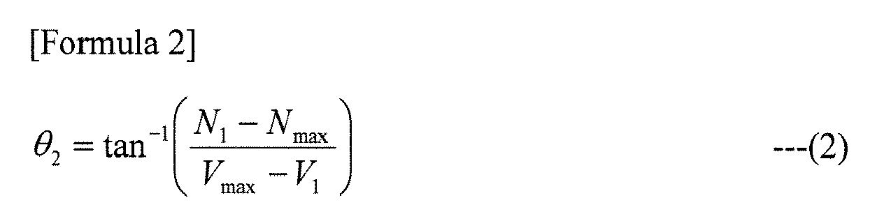
- Then, the distance calculation angle θ can be obtained by calculating θ=θ1+θ2. For example, there is a case when the largest output value is the output value of the
sensing electrode 11 as shown inFig. 6(b) , given that the electrode-head distance L is equal to or less than a predetermined range and the vicinity of thesensing electrode 11 located at the lowest position and the center position P of thehead 49a face each other substantially horizontally. - In this case, a line BCCO which connects the zero point C0 of the output value of the
sensing electrode 11 and the point (the point representing the largest output value) BC and a line ABC which connects this point BC and the point A representing the position and output value of thesensing electrode 15 located at the highest position form a distance calculation angle θ (a first distance calculation angle θ1 or the slope of the line ABC (an acute angle) θ1). - On the other hand, there is a case when the largest output value is the output value of the
sensing electrode 15 as shown inFig. 6(c) , given that, for example, the electrode-head distance L is equal to or less than a predetermined range and the vicinity of thesensing electrode 15 located at the highest position and the center position P of thehead 49a face each other substantially horizontally. In this case, a line ABA0 which connects the zero point A0 of the output value of thesensing electrode 15 and the point (the point representing the largest output value) AB and a line ABC which connects this point AB and the point C representing the position and output value of thesensing electrode 11 located at the lowest position form a distance calculation angle θ (a second distance calculation angle θ2 or the slope of the line ABC (an acute angle) θ2). - As shown in
Fig. 7(a) , the first distance calculation angle θ1 or the second distance calculation angle θ2 which can be obtained in this way exhibits a relationship of becoming larger as the electrode-head distance L becomes larger, as represented by a correlation curve T1. Likewise, as shown inFig. 7(b) , the distance calculation angle θ exhibits a relationship of becoming larger as the electrode-head distance L becomes larger, as represented by a correlation curve T2. - Accordingly, the
distance measuring device 10 according to the present example can measure the electrode-head distance L by letting thearithmetic processing circuit 28 of the detectingcircuit 20 use this distance calculation angle θ (including the first and second distance calculation angles θ1 and θ2; the same applies hereinafter). Then, the headrestposition adjusting device 100 including thisdistance measuring device 10 adjusts the position of theheadrest 43 to an appropriate position for thehead 49a based on the measurement result obtained by thedistance measuring device 10. -
Fig. 8 is a flowchart showing one example of the procedures of a distance measuring process by the method of measuring the distance between the headrest and the head according to one embodiment of the present invention. As shown inFig. 8 , first, thedistance measuring device 10 detects capacitance values which are based on capacitances sensed by thesensing electrodes 11 to 15 with respect to thehead 49a (step S10). - Next, the
distance measuring device 10 extracts the largest output value (peak output value) from among the detected capacitance values (step S11), and generates an output map by mapping the output values on such a two-dimensional coordinate system D as described above which represents the positions of thesensing electrodes 11 to 15 on its one axis and capacitance values on its other axis (step S12). - Then, the
distance measuring device 10 calculates the distance calculation angle θ in the way described above (step S13), and calculates the electrode-head distance L by, for example, comparing the calculated distance calculation angle θ with data profiling a relationship between distance and angle (step S14) thereby to measure the actual distance between theheadrest 43 and the head 49c. -
Fig. 9 is an explanatory diagram explaining a second example of outputs of the sensing electrodes of the distance measuring device according to one embodiment of the present invention.Figs. 10 are explanatory diagrams explaining third examples of outputs of the sensing electrode of the distance measuring device according to one embodiment of the present invention. Aside from the way described above with reference toFigs. 6 , thedistance measuring device 10 may also obtain the distance calculation angle θ in the following way, for example. That is, as shown inFig. 9 , thedistance measuring device 10 generates a line EF which connects a point E representing the position and output value of thesensing electrode 12 from which the smallest output value is detected among the plurality ofsensing electrodes 11 to 15 and a point F representing the position and output value of thesensing electrode 14 from which the largest output value is detected. - The
distance measuring device 10 also generates a line FFO which connects the zero point F0 of the output value of thesensing electrode 14 and the point F to form a distance calculation angle θ by the line EF and the line FFO, and measures the electrode-head distance L. In this case, since the distance calculation angle θ is equal to the acute-angle slope of the line EF, thedistance measuring device 10 can obtain the distance calculation angle θ by calculating the angle of this slope. - Alternatively, as shown in
Fig. 10(a) , when neither thesensing electrode 15 located at the highest position nor the sensingelectrode 11 located at the lowest position shows the largest output value, thedistance measuring device 10 may generate a line JK which connects a point J representing the position and output value of thesensing electrode 14 from which the largest output value is detected and a point K representing the position and output value of thesensing electrode 15 from which the smallest output value is detected among the sensing electrodes located above thesensing electrode 14. - Then, the
distance measuring device 10 may generate a line JM which connects the point J representing thesensing electrode 14 and a point M representing the position and output value of thesensing electrode 12 from which the smallest output value is detected among the sensing electrodes located under thesensing electrode 14 to form a distance calculation angle θ by the line JK and the line JM and thereby measure the electrode-head distance L. - Alternatively, as shown in
Fig. 10(b) , when either thesensing electrode 15 located at the highest position or thesensing electrode 11 located at the lowest position shows the largest output value (here, thesensing electrode 11 does), thedistance measuring device 10 may generate a line UV which connects a point U representing the position and output value of thesensing electrode 14 from which the smallest output value is detected and a point V representing the position and output value of thesensing electrode 11 from which the largest output value is detected. Thedistance measuring device 10 may also generate a line VV0 which connects the zero point V0 of the output value of thesensing electrode 11 and the point V to form a distance calculation angle θ by the line UV and the line VVO and thereby measure the electrode-head distance L. Also in this case, since the distance calculation angle θ is equal to the acute-angle slope of the line UV, thedistance measuring device 10 can obtain the distance calculation angle θ by calculating the angle of this slope. - Still alternatively, as shown in
Fig. 10(c) , when either thesensing electrode 15 located at the highest position or thesensing electrode 11 located at the lowest position shows the largest output value (here, thesensing electrode 15 does), thedistance measuring device 10 may generate a line RS which connects a point R representing the position and output value of thesensing electrode 12 from which the smallest output value is detected and a point S representing the position and output value of thesensing electrode 15 from which the largest output value is detected. Thedistance measuring device 10 may also generate a line SSO which connects the zero point S0 of the output value of thesensing electrode 15 and the point S to form a distance calculation angle θ by the line RS and the line SSO and thereby measure the electrode-head distance L. Also in this case, since the distance calculation angle θ is equal to the acute-angle slope of the line RS, thedistance measuring device 10 can obtain the distance calculation angle θ by calculating the angle of this slope. -
Fig. 11 is a block diagram showing another example of the whole configuration of a device for measuring the distance between a headrest and a head according to one embodiment of the present invention. In the following description, any portions that are the same as those already explained will be denoted by the same reference numerals and explanation thereof will not be provided. As shown inFig. 11 , the detectingcircuit 20 includes a switchingcircuit 26 connected to thesensing electrodes 11 to 15, acapacitance sensing circuit 27 which outputs information indicating a capacitance sensed by any of thesensing electrodes 11 to 15 which are to be connected to thecapacitance sensing circuit 27 intertemporally through the switchingcircuit 26, and anarithmetic processing circuit 28 which calculates a distance calculation angle θ, an electrode-head distance L, etc. based on the information output by thecapacitance sensing circuit 27 and outputs information indicating the calculation result to the motor driving circuit of thedrive motor unit 30. - This configuration of the detecting
circuit 20 allows thedistance measuring device 10 to be configured with a minimum number of capacitance sensing circuits, and enables the electrode-head distance L to be obtained by calculating the above-described distance calculation angle θ based on a result of sequentially scanning the capacitances of therespective sensing electrodes 11 to 15 which are switched among them by the switchingcircuit 26. -
Fig. 12 is a flowchart showing an example of the procedures of a position adjusting process by a headrest position adjusting method according to one embodiment of the present invention. Because the headrestposition adjusting device 100 described above includes thedistance measuring device 10 as part of its configuration, thearithmetic processing circuit 28 of the detectingcircuit 20 has a function as a control unit for controlling the entire headrestposition adjusting device 100 and a function as distance measuring means and position adjusting means. Here, a position adjusting process for adjusting theheadrest 43 in the frontward-rearward direction will be explained. - As shown in
Fig. 12 , first, the headrestposition adjusting device 100 judges whether or not the process is to be started as triggered by, for example, an ignition switch of the vehicle being turned to an accessory state or an ON state (step S100). When it is judged that the process is not to be started (step S100; N), the headrestposition adjusting device 100 terminates the series of position adjusting process according to this flowchart. - When it is judged that the process is to be started (step S100; Y), the headrest
position adjusting device 100 lets thedistance measuring device 10 perform the distance measuring process described above (step S101), and obtains the measurement result (step S102). Then, the headrestposition adjusting device 100 judges whether or not the distance calculation angle θ included in the measurement result is equal to or larger than, for example, a predetermined angle shown in the above-described data profiling a relationship between distance and angle (step S103). Note that the predetermined angle may be preset to an angle which defines a distance that is the most preferable as the electrode-head distance L (i.e., the optimum distance to thehead 49a). - When it is judged that the distance calculation angle θ is equal to or larger than the predetermined angle (step S103; Y), the headrest
position adjusting device 100 calculates the difference between the electrode-head distance L defined by the distance calculation angle θ and the distance defined by the predetermined angle, and controls thedrive motor unit 30 to move theheadrest front portion 43c frontward by an amount of the calculated difference (step S104). When it is judged that the distance calculation angle θ is smaller than the predetermined angle (step S103; N), the headrestposition adjusting device 100 calculates the difference likewise, and moves theheadrest front portion 43c rearward by an amount of the calculated difference (step S105). - After the
headrest front portion 43c is moved, the headrestposition adjusting device 100 judges whether or not the process is to be terminated by, for example, the ignition switch of the vehicle being turned OFF (step S106), and when it is judged that the process is to be terminated (step S106; Y), terminates the series of position adjusting process according to the present flowchart. When it is judged that the process is not to be terminated (step S106; N), the headrestposition adjusting device 100 goes to step S101 described above and repeats the subsequent process. - By performing the position adjusting process in this way, it is possible to perform position adjustment by using the measurement result obtained by the
distance measuring device 10 and causing a frontward/rearward following movement of theheadrest front portion 43c with respect to the position of thehead 49a. At step S103 described above, comparison is made between the distance calculation angle θ and the predetermined angle. However, for example, comparison may be made between the electrode-head distance L determined by the distance calculation angle θ and the optimum distance described above to go on to step S104 or step S105 described above. -
Fig. 13 is a flowchart showing another example of the procedures of a position adjusting process by a headrest position adjusting method according to one embodiment of the present invention. Here, a position adjusting process for adjusting theheadrest 43 in the upward-downward direction will be explained. The process from step S110 to step S112 of the present flowchart is the same as the process from step S100 to step S102 described above, and hence explanation thereof will not be provided. - As shown in
Fig. 13 , the headrestposition adjusting device 100 judges whether or not the distance calculation angle θ included in the measurement result is larger than a predetermined threshold (for example, a predetermined angle shown in the above-described data profiling a relationship between distance and angle) (step S113). When it is judged that the distance calculation angle θ is larger than the predetermined threshold (step S113; Y), which means that it is possible to judge that the electrode-head distance L is greater than a predetermined range, the headrestposition adjusting device 100 stops the position adjusting operation for the headrest backportion 43d in the height direction (step S114) and waits until a predetermined time passes (step S115; N). - On the other hand, when it is judged that the distance calculation angle θ is equal to or smaller than the predetermined threshold (step S113; N), which means that it is possible to judge that the electrode-head distance L is equal to or less than the predetermined range, the headrest
position adjusting device 100 calculates the height position of thehead 49a by using the capacitance values included in the measurement result (step S117), and performs the position adjusting operation for the headrest backportion 43d in the height direction (step S118). - Note that at step S117, the headrest
position adjusting device 100 calculates the height position of thehead 49a based on the capacitance values included in the measurement result obtained by all of thesensing electrodes 11 to 15 of thedistance measuring device 10. For example, the headrestposition adjusting device 100 calculates a position that is estimated to be the height-direction center of thehead 49a (an estimated center position) by comparing these capacitance values, and calculates the height position of thehead 49a based on this estimated center position. - When the predetermined time has passed (step S115; Y) or when the position adjusting operation has been completed (step S118), the headrest
position adjusting device 100 judges whether or not the process is to be terminated (step S116), and when it is judged that the process is to be terminated (step S116; Y), terminates the series of position adjusting process according to the present flowchart. When it is judged that the process is not to be terminated (step S116; N), the headrestposition adjusting device 100 goes to step S111 described above and repeats the subsequent process. - By performing the position adjusting process in this way, it is possible to perform position adjustment by using the measurement result obtained by the
distance measuring device 10 and moving the headrest backportion 43d in the upward-downward direction. When the electrode-head distance L is greater than the predetermined range (i.e., when the electrodes are distanced from thehead 49a), the position adjusting process stops the height-direction position adjusting operation for the headrest backportion 43d. This makes it possible to prevent an unnecessary movement of theheadrest 43, avoid giving discomfort to the occupant (vehicle occupant) as much as possible, and suppress unnecessary power consumption. -
Fig. 14 is a flowchart showing still another example of the procedures of a position adjusting process by a headrest position adjusting method according to one embodiment of the present invention. The process from step S120 to step S123 of the present flowchart is the same as the process from step S110 to step S113 described above, and hence explanation thereof will not be provided. - As shown in
Fig. 14 , when it is judged that the distance calculation angle θ included in the measurement result is larger than a predetermined threshold (for example, a predetermined angle shown in the above-described data profiling a relationship between distance and angle) (step S123; Y), the headrestposition adjusting device 100 can judge that the electrode-head distance L is greater than a predetermined range. - Hence, the headrest
position adjusting device 100 compares the capacitance value of the sensing electrode located at the highest position (for example, the sensing electrode 15) and the capacitance value of the sensing electrode located at the lowest position (for example, the sensing electrode 11) based on the measurement result (step S124) to calculate the height position of thehead 49a. On the other hand, when it is judged that the distance calculation angle θ is equal to or smaller than the predetermined threshold (step S123; N), the headrestposition adjusting device 100 can judge that the electrode-head distance L is equal to or less than the predetermined range. - Hence, the headrest
position adjusting device 100 compares the capacitance values of all of thesensing electrodes 11 to 15 based on the measurement result to calculate the height position of thehead 49a (step S125). After this, the headrestposition adjusting device 100 performs a height-direction position adjusting operation for the headrest backportion 43d based on the calculation result of step S124 or step S125 (step S126). - When the position adjusting operation has been completed, the headrest
position adjusting device 100 judges whether or not the process is to be terminated (step S127). The headrestposition adjusting device 100 terminates the series of position adjusting process according to the present flowchart when it is judged that the process is to be terminated (step S127; Y), or goes to step S121 described above and repeats the subsequent process when it is judged that the process is not to be terminated (step S127; N). - Here, comparison among the capacitance values of the
sensing electrodes 11 to 15 which are included in the measurement result results in obtaining a capacitance change amount ΔC which is based on the outputs of thesensing electrodes 11 to 15. This capacitance change amount ΔC becomes unsuitable as the information for obtaining the height position of thehead 49a when the electrode-head distance L becomes greater than a predetermined range, because in this case, there are only insignificant differences among the outputs, making it difficult to perform position adjustment. - However, comparison between the capacitance value of the
sensing electrode 15 located at the highest position and the capacitance value of thesensing electrode 11 located at the lowest position results as follows. That is, even when the electrode-head distance L is greater than the predetermined range, an output change amount ΔV (mV) based on the outputs A and B of thesensing electrodes head 49a is substantially equal to the height of the center of theheadrest 43 as shown inFig. 15(a) , but that the difference is significant otherwise as shown inFig. 15(b) . - Based on the output change amount ΔV obtained in this way, an output ratio α between the output B of the
sensing electrode 11 and the output A of thesensing electrode 15 can be obtained as α=B/(A+B) as shown inFig. 16 . An amount (mm) to move the headrest (H/R) can be calculated based on the obtained output ratio α. - Accordingly, given that the amount to move the headrest when the height of the center position P of the
head 49a is horizontally equal to the height of the center of theheadrest 43 is 0mm, a control signal is output to thedrive motor unit 30 to move the headrest backportion 43d upward (in a "+" direction) when the output ratio α is close to 0, or to move the headrest backportion 43d downward (in a "-" direction) when the output ratio α is close to 1. - In this way, the headrest
position adjusting device 100 according to the present example can obtain the position of thehead 49a through the step S124 described above based on the capacitance values of thesensing electrodes sensing electrodes 11 to 15 when the distance calculation angle θ is equal to or smaller than the predetermined threshold and hence the electrode-head distance L is equal to or less than the predetermined range. Therefore, the headrestposition adjusting device 100 can adjust the position of theheadrest 43 highly accurately with a simple configuration, and can prevent accidents due to failure to adjust the position of theheadrest 43, such as cervical spine injury of thehuman body 49 in a car crash, etc. - At step S113 and step S123 described above, comparison is made between the distance calculation angle θ and the predetermined threshold. However, for example, comparison may be made between the electrode-head distance L determined by the distance calculation angle θ and the optimum distance described above to perform the subsequent process.
- The above-described embodiment has explained that position adjustment is performed by moving the
headrest front portion 43c or the headrest backportion 43d in the frontward-rearward direction or in the upward-downward direction through the position adjusting processes shown inFigs. 12 to 14 . However, position adjustment may be performed by, for example, executing these processes in parallel based on the measurement result obtained from thedistance measuring device 10, such that the position of theheadrest 43 may be adjusted to a position that is appropriate for thehead 49a in all of the frontward-rearward, upward-downward, and leftward-rightward directions. - The
distance measuring device 10 may measure the electrode-head distance L by letting thearithmetic processing circuit 28 select a preset slope coefficient for the distance calculation angle θ based on the sensing electrode from which the largest output value is measured when capacitance values are measured from thesensing electrodes 11 to 15 and make a comparison based on the slope coefficient. - The
distance measuring device 10 may include, for example, three sensing electrodes which are located at the highest position, the lowest position, and the middle position between these positions of theheadrest front portion 43c, and measure the electrode-head distance L by calculating the distance calculation angle θ based on the capacitance values of these sensing electrodes. -
- 10
- distance measuring device
- 11 to 15
- sensing electrode
- 19
- substrate
- 20
- detecting circuit
- 21 to 25
- capacitance sensing circuit
- 26
- switching circuit
- 27
- capacitance sensing circuit
- 28
- arithmetic processing circuit
- 29
- harness
- 30
- drive motor unit
- 40
- seat
- 41
- backrest (seat back)
- 42
- sitting portion
- 43
- headrest
- 43a
- support shaft
- 43b
- support shaft
- 43c
- headrest front portion
- 43d
- headrest back portion
- 49
- human body
- 49a
- head
- 100
- headrest position adjusting device
Claims (24)
- A device for measuring a distance between a headrest and a head, comprising:a plurality of sensing electrodes which are provided in a headrest provided on a seat of a vehicle for sensing capacitances between a head of a human body sitting on the seat and the headrest, the sensing electrodes being provided side by side along a height direction of the headrest;a detecting circuit which detects capacitance values which are based on the capacitances from the plurality of sensing electrodes; anddistance measuring means which measures an electrode-head distance indicating a distance between the headrest and the head, in accordance with detection results detected by the detecting circuit,wherein when the sensing electrode located at a highest position of the headrest or the sensing electrode located at a lowest position thereof among the plurality of sensing electrodes does not show a largest capacitance, the distance measuring means measures the electrode-head distance by calculating, on a two-dimensional coordinate system representing positions of the plurality of sensing electrodes on its one axis and the capacitance values detected by the detecting circuit on its other axis, a distance calculation angle formed by a line which connects a point representing the position and capacitance value of the sensing electrode located at the highest position of the headrest and a point representing the position and capacitance value of the sensing electrode from which a largest capacitance value is detected and a line which connects a point representing the position and capacitance value of the sensing electrode located at the lowest position of the headrest and the point representing the position and capacitance value of the sensing electrode from which the largest capacitance value is detected, andwhen the sensing electrode located at the highest position of the headrest or the sensing electrode located at the lowest position thereof shows the largest capacitance, the distance measuring means measures the electrode-head distance by calculating, on the two-dimensional coordinate system, an angle of a slope of a line which connects the point representing the position and capacitance value of the sensing electrode located at the highest position of the headrest and the point representing the position and capacitance value of the sensing electrode located at the lowest position of the headrest.
- A device for measuring a distance between a headrest and a head, comprising:a plurality of sensing electrodes which are provided in a headrest provided on a seat of a vehicle for sensing capacitances between a head of a human body sitting on the seat and the headrest, the sensing electrodes being provided side by side along a height direction of the headrest;a detecting circuit which detects capacitance values which are based on the capacitances from the plurality of sensing electrodes; anddistance measuring means which measures an electrode-head distance indicating a distance between the headrest and the head, in accordance with detection results detected by the detecting circuit,wherein the distance measuring means measures the electrode-head distance by calculating, on a two-dimensional coordinate system representing positions of the plurality of sensing electrodes on its one axis and the capacitance values detected by the detecting circuit on its other axis, an angle of a slope of a line which connects a point representing the position and capacitance value of the sensing electrode from which a smallest capacitance value is detected among the plurality of sensing electrodes and a point representing the position and capacitance value of the sensing electrode from which a largest capacitance value is detected among the plurality of sensing electrodes.
- A device for measuring a distance between a headrest and a head, comprising:a plurality of sensing electrodes which are provided in a headrest provided on a seat of a vehicle for sensing capacitances between a head of a human body sitting on the seat and the headrest, the sensing electrodes being provided side by side along a height direction of the headrest;a detecting circuit which detects capacitance values which are based on the capacitances from the plurality of sensing electrodes; anddistance measuring means which measures an electrode-head distance indicating a distance between the headrest and the head, in accordance with detection results detected by the detecting circuit,wherein when the sensing electrode located at a highest position of the headrest or the sensing electrode located at a lowest position thereof among the plurality of sensing electrodes does not show a largest capacitance, the distance measuring means measures the electrode-head distance by calculating, on a two-dimensional coordinate system representing positions of the plurality of sensing electrodes on its one axis and the capacitance values detected by the detecting circuit on its other axis, a distance calculation angle formed by a line which connects a point representing the position and capacitance value of the sensing electrode from which a largest capacitance value is detected and a point representing the position and capacitance value of the sensing electrode from which a smallest capacitance value is detected among the sensing electrodes located above the sensing electrode from which the largest capacitance value is detected and a line which connects the point representing the position and capacitance value of the sensing electrode from which the largest capacitance value is detected and a point representing the position and capacitance value of the sensing electrode from which a smallest capacitance value is detected among the sensing electrodes located under the sensing electrode from which the largest capacitance value is detected, andwhen the sensing electrode located at the highest position of the headrest or the sensing electrode located at the lowest position thereof shows the largest capacitance, the distance measuring means measures the electrode-head distance by calculating, on the two-dimensional coordinate system, an angle of a slope of a line which connects a point representing the position and capacitance value of the sensing electrode from which a smallest capacitance value is detected and a point representing the position and capacitance value of the sensing electrode from which a largest capacitance value is detected.
- The device for measuring a distance between a headrest and a head according to claim 1 or 3,
wherein the distance measuring means obtains a first distance calculation angle formed by the line which connects the point representing the sensing electrode located at the highest position and the point representing the sensing electrode from which the largest capacitance value is detected and a base line which extends to the one axis perpendicularly to the one axis from the point representing the sensing electrode from which the largest capacitance value is detected and a second distance calculation angle formed by the line which connects the point representing the sensing electrode located at the lowest position and the point representing the sensing electrode from which the largest capacitance value is detected and the base line, and calculates the distance calculation angle based on these first and second distance calculation angles. - The device for measuring a distance between a headrest and a head according to any one of claims 1 to 4,
wherein the distance measuring means measures the electrode-head distance by comparing the distance calculation angle with preset data which profiles a relationship between distance and angle. - The device for measuring a distance between a headrest and a head according to any one of claims 1 to 5,
wherein the plurality of sensing electrodes are provided in the headrest at a portion closer to a front surface of the headrest and formed in a rectangular strip shape having its longer dimension extend in a width direction perpendicular to the height direction, and
the detecting circuit includes a plurality of capacitance sensing circuits which are connected one-to-one to the plurality of sensing electrodes, and output the capacitance values which are based on the capacitances sensed by the sensing electrodes. - The device for measuring a distance between a headrest and a head according to any one of claims 1 to 5,
wherein the plurality of sensing electrodes are provided in the headrest at a portion closer to a front surface of the headrest and formed in a rectangular strip shape having its longer dimension extend in a width direction perpendicular to the height direction, and
the detecting circuit includes a switching circuit connected to the plurality of sensing electrodes, and a capacitance sensing circuit which outputs the capacitance value which is based on the capacitance sensed by any of the sensing electrodes which are to be connected to the capacitance sensing circuit intertemporally through the switching circuit. - A headrest position adjusting device, comprising:the device for measuring a distance between a headrest and a head according to any one of claims 1 to 7; andposition adjusting means which adjusts a position of the headrest to an appropriate position for the head based on a measurement result from the device for measuring a distance.
- The headrest position adjusting device according to claim 8,
wherein the position adjusting means adjusts the position of the headrest by moving the headrest in a frontward direction or rearward direction of the vehicle based on the distance calculation angle which is included in the measurement result such that the distance calculation angle becomes a predetermined angle. - The headrest position adjusting device according to claim 8 or 9,
wherein the position adjusting means compares the distance calculation angle included in the measurement result with a predetermined threshold, and when the distance calculation angle is larger than the predetermined threshold, stops a position adjusting operation for the headrest at least in the height direction. - The headrest position adjusting device according to claim 10,
wherein when the position adjusting means stops the position adjusting operation for the headrest for a predetermined time, after the predetermined time passes, the position adjusting means again compares the distance calculation angle with the predetermined threshold. - The headrest position adjusting device according to claim 8 or 9,
wherein when the distance calculation angle included in the measurement result is larger than a predetermined threshold, the position adjusting means adjusts the position of the headrest by moving the headrest in an upward direction or downward direction of the vehicle by using the capacitance values which are detected by the detecting circuit based on the capacitances from at least the sensing electrode located at the highest position and the sensing electrode located at the lowest position among the plurality of sensing electrodes. - The headrest position adjusting device according to any one of claims 8 to 12,
wherein when the distance calculation angle included in the measurement result is equal to or smaller than a predetermined threshold, the position adjusting means calculates an appropriate position of the headrest with respect to the head by using the capacitance values which are detected by the detecting circuit based on the capacitances from the plurality of sensing electrodes, and adjusts the position of the headrest to the appropriate position. - A method for measuring a distance between a headrest and a head, comprising:a sensing step of sensing capacitances between a head of a human body sitting on a seat of a vehicle and a headrest provided on the seat by means of a plurality of sensing electrodes which are provided in the headrest side by side along a height direction of the headrest;a detecting step of detecting capacitance values which are based on the capacitances sensed in the sensing step; anda distance measuring step of measuring an electrode-head distance indicating a distance between the headrest and the head, in accordance with detection results detected in the detecting step,wherein when the sensing electrode located at a highest position of the headrest or the sensing electrode located at a lowest position thereof among the plurality of sensing electrodes does not show a largest capacitance, the distance measuring step measures the electrode-head distance by calculating, on a two-dimensional coordinate system representing positions of the plurality of sensing electrodes on its one axis and the capacitance values detected in the detecting step on its other axis, a distance calculation angle formed by a line which connects a point representing the position and capacitance value of the sensing electrode located at the highest position of the headrest and a point representing the position and capacitance value of the sensing electrode from which a largest capacitance value is detected and a line which connects a point representing the position and capacitance value of the sensing electrode located at the lowest position of the headrest and the point representing the position and capacitance value of the sensing electrode from which the largest capacitance value is detected, andwhen the sensing electrode located at the highest position of the headrest or the sensing electrode located at the lowest position thereof shows the largest capacitance, the distance measuring step measures the electrode-head distance by calculating, on the two-dimensional coordinate system, an angle of a slope of a line which connects the point representing the position and capacitance value of the sensing electrode located at the highest position of the headrest and the point representing the position and capacitance value of the sensing electrode located at the lowest position of the headrest.
- A method for measuring a distance between a headrest and a head, comprising:a sensing step of sensing capacitances between a head of a human body sitting on a seat of a vehicle and a headrest provided on the seat by means of a plurality of sensing electrodes which are provided in the headrest side by side along a height direction of the headrest;a detecting step of detecting capacitance values which are based on the capacitances sensed in the sensing step; anda distance measuring step of measuring an electrode-head distance indicating a distance between the headrest and the head, in accordance with detection results detected in the detecting step,wherein the distance measuring step measures the electrode-head distance by calculating, on a two-dimensional coordinate system representing positions of the plurality of sensing electrodes on its one axis and the capacitance values detected in the detecting step on its other axis, an angle of a slope of a line which connects a point representing the position and capacitance value of the sensing electrode from which a smallest capacitance value is detected among the plurality of sensing electrodes and a point representing the position and capacitance value of the sensing electrode from which a largest capacitance value is detected among the plurality of sensing electrodes.
- A method for measuring a distance between a headrest and a head, comprising:a sensing step of sensing capacitances between a head of a human body sitting on a seat of a vehicle and a headrest provided on the seat by means of a plurality of sensing electrodes which are provided in the headrest side by side along a height direction of the headrest;a detecting step of detecting capacitance values which are based on the capacitances sensed in the sensing step; anda distance measuring step of measuring an electrode-head distance indicating a distance between the headrest and the head, in accordance with detection results detected in the detecting step,wherein when the sensing electrode located at a highest position of the headrest or the sensing electrode located at a lowest position thereof among the plurality of sensing electrodes does not show a largest capacitance, the distance measuring step measures the electrode-head distance by calculating, on a two-dimensional coordinate system representing positions of the plurality of sensing electrodes on its one axis and the capacitance values detected in the detecting step on its other axis, a distance calculation angle formed by a line which connects a point representing the position and capacitance value of the sensing electrode from which a largest capacitance value is detected and a point representing the position and capacitance value of the sensing electrode from which a smallest capacitance value is detected among the sensing electrodes located above the sensing electrode from which the largest capacitance value is detected and a line which connects the point representing the position and capacitance value of the sensing electrode from which the largest capacitance value is detected and a point representing the position and capacitance value of the sensing electrode from which a smallest capacitance value is detected among the sensing electrodes located under the sensing electrode from which the largest capacitance value is detected, andwhen the sensing electrode located at the highest position of the headrest or the sensing electrode located at the lowest position thereof shows the largest capacitance, the distance measuring step measures the electrode-head distance by calculating, on the two-dimensional coordinate system, an angle of a slope of a line which connects a point representing the position and capacitance value of the sensing electrode from which a smallest capacitance value is detected and a point representing the position and capacitance value of the sensing electrode from which a largest capacitance value is detected.
- The method for measuring a distance between a headrest and a head according to claim 14 or 16,
wherein the distance measuring step obtains a first distance calculation angle formed by the line which connects the point representing the sensing electrode located at the highest position and the point representing the sensing electrode from which the largest capacitance value is detected and a base line which extends to the one axis perpendicularly to the one axis from the point representing the sensing electrode from which the largest capacitance value is detected and a second distance calculation angle formed by the line which connects the point representing the sensing electrode located at the lowest position and the point representing the sensing electrode from which the largest capacitance value is detected and the base line, and calculates the distance calculation angle based on these first and second distance calculation angles. - The method for measuring a distance between a headrest and a head according to any one of claims 14 to 17,
wherein the distance measuring step measures the electrode-head distance by comparing the distance calculation angle with preset data which profiles a relationship between distance and angle. - A headrest position adjusting method, comprising:the method for measuring a distance between a headrest and a head according to any one of claims 14 to 18; anda position adjusting step of adjusting a position of the headrest to an appropriate position for the head based on a measurement result measured by the method for measuring a distance.
- The headrest position adjusting method according to claim 19,
wherein the position adjusting step adjusts the position of the headrest by moving the headrest in a frontward direction or rearward direction of the vehicle based on the distance calculation angle which is included in the measurement result, such that the distance calculation angle becomes a predetermined angle. - The headrest position adjusting method according to claim 19 or 20,
wherein the position adjusting step compares the distance calculation angle included in the measurement result with a predetermined threshold, and when the distance calculation angle is larger than the predetermined threshold, stops a position adjusting operation for the headrest at least in the height direction. - The headrest position adjusting method according to claim 21,
wherein when the position adjusting step stops the position adjusting operation for the headrest for a predetermined time, after the predetermined time passes, the position adjusting step again compares the distance calculation angle with the predetermined threshold. - The headrest position adjusting method according to claim 19 or 20,
wherein when the distance calculation angle included in the measurement result is larger than a predetermined threshold, the position adjusting step adjusts the position of the headrest by moving the headrest in an upward direction or downward direction of the vehicle by using the capacitance values which are detected in the detecting step based on the capacitances from at least the sensing electrode located at the highest position and the sensing electrode located at the lowest position among the plurality of sensing electrodes. - The headrest position adjusting method according to any one of claims 19 to 23,
wherein when the distance calculation angle included in the measurement result is equal to or smaller than a predetermined threshold, the position adjusting step calculates an appropriate position of the headrest with respect to the head by using the capacitance values which are detected in the detecting step based on the capacitances from the plurality of sensing electrodes, and adjusts the position of the headrest to the appropriate position.
Applications Claiming Priority (2)
| Application Number | Priority Date | Filing Date | Title |
|---|---|---|---|
| JP2009072028 | 2009-03-24 | ||
| PCT/JP2010/055067 WO2010110306A1 (en) | 2009-03-24 | 2010-03-24 | Device for measuring distance between headrest and head, method for measuring distance between headrest and head, headrest position adjusting device, and headrest position adjusting method |
Publications (2)
| Publication Number | Publication Date |
|---|---|
| EP2413091A1 true EP2413091A1 (en) | 2012-02-01 |
| EP2413091A4 EP2413091A4 (en) | 2017-08-30 |
Family
ID=42781000
Family Applications (1)
| Application Number | Title | Priority Date | Filing Date |
|---|---|---|---|
| EP10756102.9A Withdrawn EP2413091A4 (en) | 2009-03-24 | 2010-03-24 | Device for measuring distance between headrest and head, method for measuring distance between headrest and head, headrest position adjusting device, and headrest position adjusting method |
Country Status (6)
| Country | Link |
|---|---|
| US (1) | US8653835B2 (en) |
| EP (1) | EP2413091A4 (en) |
| JP (1) | JP5509505B2 (en) |
| KR (1) | KR20110129484A (en) |
| CN (1) | CN102362144B (en) |
| WO (1) | WO2010110306A1 (en) |
Cited By (1)
| Publication number | Priority date | Publication date | Assignee | Title |
|---|---|---|---|---|
| WO2017063084A1 (en) | 2015-10-16 | 2017-04-20 | Dalhousie University | Systems and methods for monitoring patient motion via capacitive position sensing |
Families Citing this family (5)
| Publication number | Priority date | Publication date | Assignee | Title |
|---|---|---|---|---|
| JP5005767B2 (en) * | 2007-08-28 | 2012-08-22 | 株式会社フジクラ | Headrest position adjustment device and headrest position adjustment method |
| CN102947128A (en) * | 2010-06-23 | 2013-02-27 | 株式会社藤仓 | Device for measuring the distance between a head and a headrest, headrest position-adjustment device using said device, method for measuring the distance between a head and a headrest, and headrest position-adjustment method using said method |
| US9494630B2 (en) * | 2012-07-30 | 2016-11-15 | Beijing Lenovo Software Ltd. | Method and system for adjusting electric field intensity |
| KR101519748B1 (en) * | 2013-12-10 | 2015-05-12 | 현대자동차주식회사 | A carelessness detmination method of the driver and an apparatus for this |
| JP5897225B2 (en) * | 2014-03-11 | 2016-03-30 | 三菱電機株式会社 | Detector and hand dryer |
Family Cites Families (16)
| Publication number | Priority date | Publication date | Assignee | Title |
|---|---|---|---|---|
| JPS6013181A (en) | 1983-06-30 | 1985-01-23 | 丸高工業株式会社 | Hanging device of moving room partition wall |
| JPH01285801A (en) | 1988-05-12 | 1989-11-16 | Koko Res Kk | Proximity distance sensor and discriminating apparatus of shape |
| US5848661A (en) * | 1996-10-22 | 1998-12-15 | Lear Corporation | Vehicle seat assembly including at least one occupant sensing system and method of making same |
| DE19651670C1 (en) * | 1996-12-12 | 1998-02-12 | Daimler Benz Ag | Device to adjust vehicle seat to correct sitting position |
| US5871232A (en) * | 1997-01-17 | 1999-02-16 | Automotive Systems, Laboratory, Inc. | Occupant position sensing system |
| JP3347069B2 (en) | 1998-08-31 | 2002-11-20 | 日本電気株式会社 | Occupant detection system |
| DE102006002919B4 (en) | 2005-01-24 | 2008-09-04 | Denso Corp., Kariya | Capacitive sensor and occupant detection system |
| JP4412197B2 (en) | 2005-02-17 | 2010-02-10 | 株式会社デンソー | Occupant detection sensor |
| JP4306673B2 (en) | 2005-11-08 | 2009-08-05 | トヨタ自動車株式会社 | Crew protection device |
| JP4018112B2 (en) | 2005-11-17 | 2007-12-05 | アイシン精機株式会社 | Vehicle headrest device |
| JP4342521B2 (en) * | 2006-01-30 | 2009-10-14 | アイシン精機株式会社 | Headrest device |
| JP2007280352A (en) | 2006-03-17 | 2007-10-25 | Toyota Motor Corp | Gaze direction determination device |
| DE102006023102A1 (en) | 2006-05-16 | 2007-11-22 | Grammer Ag | Headrest for a vehicle seat |
| EP2141047B1 (en) * | 2007-04-24 | 2012-08-29 | Fujikura, Ltd. | Head rest position adjusting apparatus and head rest position adjusting method |
| DE102007039659B3 (en) | 2007-08-22 | 2008-08-21 | MENTOR GmbH & Co. Präzisions-Bauteile KG | Head restraint for vehicle seat, has signal electrodes attached to compensation mechanism that is attached to evaluation electronic unit, where compensation mechanism provides compensation condenser mechanism with rear area of restraint |
| JP5005767B2 (en) | 2007-08-28 | 2012-08-22 | 株式会社フジクラ | Headrest position adjustment device and headrest position adjustment method |
-
2010
- 2010-03-24 EP EP10756102.9A patent/EP2413091A4/en not_active Withdrawn
- 2010-03-24 US US13/260,165 patent/US8653835B2/en not_active Expired - Fee Related
- 2010-03-24 CN CN201080013717XA patent/CN102362144B/en not_active Expired - Fee Related
- 2010-03-24 JP JP2011506079A patent/JP5509505B2/en not_active Expired - Fee Related
- 2010-03-24 KR KR1020117024742A patent/KR20110129484A/en not_active Abandoned
- 2010-03-24 WO PCT/JP2010/055067 patent/WO2010110306A1/en not_active Ceased
Non-Patent Citations (1)
| Title |
|---|
| See references of WO2010110306A1 * |
Cited By (5)
| Publication number | Priority date | Publication date | Assignee | Title |
|---|---|---|---|---|
| WO2017063084A1 (en) | 2015-10-16 | 2017-04-20 | Dalhousie University | Systems and methods for monitoring patient motion via capacitive position sensing |
| EP3361978A4 (en) * | 2015-10-16 | 2019-05-29 | Dalhousie University | SYSTEMS AND METHODS FOR MONITORING PATIENT MOVEMENT THROUGH CAPACITIVE POSITION DETECTION |
| US10857390B2 (en) | 2015-10-16 | 2020-12-08 | Dalhousie University | Systems and methods for monitoring patient motion via capacitive position sensing |
| US11612763B2 (en) | 2015-10-16 | 2023-03-28 | Dalhousie University | Systems and methods for monitoring patient motion via capacitive position sensing |
| US11911632B2 (en) | 2015-10-16 | 2024-02-27 | Dalhousie University | Systems and methods for monitoring patient motion via capacitive position sensing |
Also Published As
| Publication number | Publication date |
|---|---|
| KR20110129484A (en) | 2011-12-01 |
| JPWO2010110306A1 (en) | 2012-09-27 |
| US8653835B2 (en) | 2014-02-18 |
| US20120025850A1 (en) | 2012-02-02 |
| EP2413091A4 (en) | 2017-08-30 |
| CN102362144A (en) | 2012-02-22 |
| JP5509505B2 (en) | 2014-06-04 |
| CN102362144B (en) | 2013-12-11 |
| WO2010110306A1 (en) | 2010-09-30 |
Similar Documents
| Publication | Publication Date | Title |
|---|---|---|
| EP2413092A1 (en) | Device for measuring distance between headrest and head, method for measuring distance between headrest and head, headrest position adjusting device, and headrest position adjusting method | |
| US8690252B2 (en) | Headrest position adjusting device and headrest position adjusting method | |
| EP2141047B1 (en) | Head rest position adjusting apparatus and head rest position adjusting method | |
| US8653835B2 (en) | Device for measuring distance between headrest and head, method for measuring distance between headrest and head, headrest position adjusting device, and headrest position adjusting method | |
| JP4834178B2 (en) | Headrest position adjustment device and headrest position adjustment method | |
| KR20110089858A (en) | Capacitive Sensor | |
| CN101821128B (en) | Headrest position adjustment device and headrest position adjustment method | |
| JP4588738B2 (en) | Headrest position adjusting device and position adjusting method | |
| JP2010221819A (en) | Headrest position adjustment device | |
| JP5339267B2 (en) | Headrest position adjustment device and headrest position adjustment method | |
| JP2010188974A (en) | Head rest position adjusting device and head rest position adjusting method |
Legal Events
| Date | Code | Title | Description |
|---|---|---|---|
| PUAI | Public reference made under article 153(3) epc to a published international application that has entered the european phase |
Free format text: ORIGINAL CODE: 0009012 |
|
| 17P | Request for examination filed |
Effective date: 20111020 |
|
| AK | Designated contracting states |
Kind code of ref document: A1 Designated state(s): AT BE BG CH CY CZ DE DK EE ES FI FR GB GR HR HU IE IS IT LI LT LU LV MC MK MT NL NO PL PT RO SE SI SK SM TR |
|
| DAX | Request for extension of the european patent (deleted) | ||
| RIN1 | Information on inventor provided before grant (corrected) |
Inventor name: NOGUCHI, YUKI Inventor name: YAMAGUCHI, YUICHIRO Inventor name: OSAKI, TAKUYA |
|
| RA4 | Supplementary search report drawn up and despatched (corrected) |
Effective date: 20170727 |
|
| RIC1 | Information provided on ipc code assigned before grant |
Ipc: B60N 2/48 20060101ALI20170721BHEP Ipc: G01B 7/00 20060101AFI20170721BHEP Ipc: G01B 7/14 20060101ALI20170721BHEP Ipc: G01B 7/28 20060101ALI20170721BHEP |
|
| GRAP | Despatch of communication of intention to grant a patent |
Free format text: ORIGINAL CODE: EPIDOSNIGR1 |
|
| RIC1 | Information provided on ipc code assigned before grant |
Ipc: G01B 7/00 20060101AFI20180531BHEP Ipc: G01B 7/28 20060101ALI20180531BHEP Ipc: G01B 7/14 20060101ALI20180531BHEP |
|
| INTG | Intention to grant announced |
Effective date: 20180622 |
|
| STAA | Information on the status of an ep patent application or granted ep patent |
Free format text: STATUS: THE APPLICATION IS DEEMED TO BE WITHDRAWN |
|
| 18D | Application deemed to be withdrawn |
Effective date: 20181103 |