EP2413014A1 - Retention system - Google Patents
Retention system Download PDFInfo
- Publication number
- EP2413014A1 EP2413014A1 EP11172004A EP11172004A EP2413014A1 EP 2413014 A1 EP2413014 A1 EP 2413014A1 EP 11172004 A EP11172004 A EP 11172004A EP 11172004 A EP11172004 A EP 11172004A EP 2413014 A1 EP2413014 A1 EP 2413014A1
- Authority
- EP
- European Patent Office
- Prior art keywords
- pin
- housing
- retaining pin
- sleeve
- blind hole
- Prior art date
- Legal status (The legal status is an assumption and is not a legal conclusion. Google has not performed a legal analysis and makes no representation as to the accuracy of the status listed.)
- Granted
Links
- 230000014759 maintenance of location Effects 0.000 title description 38
- 230000000717 retained effect Effects 0.000 claims abstract description 8
- 238000004891 communication Methods 0.000 claims description 11
- 238000000034 method Methods 0.000 claims description 9
- 239000007769 metal material Substances 0.000 claims description 2
- 238000013461 design Methods 0.000 description 3
- 239000012530 fluid Substances 0.000 description 2
- 238000003780 insertion Methods 0.000 description 2
- 230000037431 insertion Effects 0.000 description 2
- 238000009434 installation Methods 0.000 description 2
- 239000008188 pellet Substances 0.000 description 2
- 229910000831 Steel Inorganic materials 0.000 description 1
- XAGFODPZIPBFFR-UHFFFAOYSA-N aluminium Chemical compound [Al] XAGFODPZIPBFFR-UHFFFAOYSA-N 0.000 description 1
- 229910052782 aluminium Inorganic materials 0.000 description 1
- 230000000712 assembly Effects 0.000 description 1
- 238000000429 assembly Methods 0.000 description 1
- 238000007796 conventional method Methods 0.000 description 1
- 239000000463 material Substances 0.000 description 1
- 230000007246 mechanism Effects 0.000 description 1
- 238000012986 modification Methods 0.000 description 1
- 230000004048 modification Effects 0.000 description 1
- 238000005057 refrigeration Methods 0.000 description 1
- 230000003068 static effect Effects 0.000 description 1
- 239000010959 steel Substances 0.000 description 1
Images


Classifications
-
- F—MECHANICAL ENGINEERING; LIGHTING; HEATING; WEAPONS; BLASTING
- F16—ENGINEERING ELEMENTS AND UNITS; GENERAL MEASURES FOR PRODUCING AND MAINTAINING EFFECTIVE FUNCTIONING OF MACHINES OR INSTALLATIONS; THERMAL INSULATION IN GENERAL
- F16L—PIPES; JOINTS OR FITTINGS FOR PIPES; SUPPORTS FOR PIPES, CABLES OR PROTECTIVE TUBING; MEANS FOR THERMAL INSULATION IN GENERAL
- F16L55/00—Devices or appurtenances for use in, or in connection with, pipes or pipe systems
- F16L55/07—Arrangement or mounting of devices, e.g. valves, for venting or aerating or draining
-
- F—MECHANICAL ENGINEERING; LIGHTING; HEATING; WEAPONS; BLASTING
- F16—ENGINEERING ELEMENTS AND UNITS; GENERAL MEASURES FOR PRODUCING AND MAINTAINING EFFECTIVE FUNCTIONING OF MACHINES OR INSTALLATIONS; THERMAL INSULATION IN GENERAL
- F16L—PIPES; JOINTS OR FITTINGS FOR PIPES; SUPPORTS FOR PIPES, CABLES OR PROTECTIVE TUBING; MEANS FOR THERMAL INSULATION IN GENERAL
- F16L37/00—Couplings of the quick-acting type
- F16L37/22—Couplings of the quick-acting type in which the connection is maintained by means of balls, rollers or helical springs under radial pressure between the parts
-
- F—MECHANICAL ENGINEERING; LIGHTING; HEATING; WEAPONS; BLASTING
- F16—ENGINEERING ELEMENTS AND UNITS; GENERAL MEASURES FOR PRODUCING AND MAINTAINING EFFECTIVE FUNCTIONING OF MACHINES OR INSTALLATIONS; THERMAL INSULATION IN GENERAL
- F16B—DEVICES FOR FASTENING OR SECURING CONSTRUCTIONAL ELEMENTS OR MACHINE PARTS TOGETHER, e.g. NAILS, BOLTS, CIRCLIPS, CLAMPS, CLIPS OR WEDGES; JOINTS OR JOINTING
- F16B2200/00—Constructional details of connections not covered for in other groups of this subclass
- F16B2200/69—Redundant disconnection blocking means
- F16B2200/71—Blocking disengagement of catches or keys
-
- Y—GENERAL TAGGING OF NEW TECHNOLOGICAL DEVELOPMENTS; GENERAL TAGGING OF CROSS-SECTIONAL TECHNOLOGIES SPANNING OVER SEVERAL SECTIONS OF THE IPC; TECHNICAL SUBJECTS COVERED BY FORMER USPC CROSS-REFERENCE ART COLLECTIONS [XRACs] AND DIGESTS
- Y10—TECHNICAL SUBJECTS COVERED BY FORMER USPC
- Y10T—TECHNICAL SUBJECTS COVERED BY FORMER US CLASSIFICATION
- Y10T29/00—Metal working
- Y10T29/49—Method of mechanical manufacture
- Y10T29/49815—Disassembling
- Y10T29/49817—Disassembling with other than ancillary treating or assembling
Definitions
- the present invention relates to a retention system and more particularly to a retention system suitable for use in hydraulic flow systems.
- Hydraulic units are used in a variety of applications, including refrigeration systems. Most units consist of a housing with one or more bores in which valves or other components are installed to control the performance of the assembly and control pressure and flow within assembly passageways. The valves need a retention device to hold them in place. The most common types of retention for these devices are threaded sleeves or spools which need to be torqued into place. Due to thermal and vibrational forces acting on flow systems, especially those in the aerospace industry, threaded closures run the risk of becoming loose and backing out. Therefore, secondary retention methods are required to accompany the threaded closures. Some common secondary retention devices used are lock-wire (wire is mechanically attached to the threaded member and locked to another place), locking pellets and locking inserts. While these conventional methods work, they require adequate spatial envelope to fit within a system. In addition, they also place additional constraints on how the system may be set up, as well as adding weight to the system.
- a system to retain a sleeve within a housing includes a sleeve, a spring loaded retaining pin which can be moved to be fully within the sleeve, a locking pin to hold the retaining pin within the sleeve when the sleeve is being set into or withdrawn from the housing, and an annular recess in the housing to receive the retaining pin when the sleeve is set in the housing, the locking pin is removed and the retaining pin is pushed outward by the spring.
- the sleeve is retained within the housing when the spring pushes the retaining pin outward so that the retaining pin engages the annular recess in the housing.
- a method of retaining a sleeve within a housing includes inserting a first spring loaded retaining pin into a first blind hole within a sleeve; moving the first retaining pin so that the spring is compressed and the first retaining pin is totally inside the sleeve by engaging a part of the first retaining pin with a tool going though a first slot in communication with at least part of the first blind hole; and inserting a first locking pin into a first locking hole which intersects with the first blind hole so that the first locking pin holds the first retaining pin within the sleeve, compressing the springs. It further includes inserting the sleeve into the housing and removing the locking pin to allow the first retaining pin to engage an annular recess in the housing.
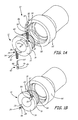
- FIG. 1A is an exploded view of the retention device of the current invention.
- FIG. 1B is a perspective view of the retention device of the current invention being inserted into a housing.
- FIG. 2A shows an end view of an embodiment of a retention device according to the current invention set in a housing.
- FIG. 2B shows a cross sectional view of the retention device of FIG. 2A along line 2B-2B.
- FIG. 2C shows a cross section view of the retention device of FIG. 2B along the line 2C-2C.
- FIG. 3A shows a perspective view of an embodiment of the retention device of the current invention in a housing, and with a tool compressing a retaining pin within the sleeve to enable removal of the sleeve from the housing.
- FIG. 3B shows a cross sectional view of an embodiment of the retention device of the current invention with the pins compressed into the sleeve and held there by locking pins.
- FIG. 4 shows a cross-sectional view of a section of a flow system which uses an embodiment of the retaining device of the current invention.
- FIG. 1A is an exploded view of the retention system of the current invention.
- FIG. 1B is a perspective view of the retention system of the current invention being inserted into a housing.
- FIGS. 1A-1B include retention system 10 with valve sleeve 12 (which includes front face 14; flange 16; first blind hole 18 with slot 20 and locking hole 22, and second blind hole 24 with slot 26 and locking hole 28), first retaining pin 30 (with head 32, neck 34, shoulder 36 and stem 38) with spring 40, and second retaining pin 42 (with head 44, neck 46, shoulder 48 and stem 50) with spring 52, first locking pin 54, second locking pin 56, O-ring 58 and housing 60 with an annular recess 62 (see FIGS. 2B-2C ).
- valve sleeve 12 which includes front face 14; flange 16; first blind hole 18 with slot 20 and locking hole 22, and second blind hole 24 with slot 26 and locking hole 28
- first retaining pin 30 with head 32, neck 34, shoulder 36 and stem 38
- Blind holes 18, 24 are of sufficient length so that each respective spring can compress and heads 32, 44 of retaining pins 30, 42 can fit entirely within flange 16 of valve sleeve 12.
- Retaining pins 30, 42 can be made of a metallic material such as steel or aluminum or a plastic, depending on requirements of the system.
- FIG. 2A shows an end view of an embodiment of a retention system according to the current invention set in a housing.
- FIG. 2B shows a cross sectional view of the retention system of FIG. 2A along line 2B-2B.
- FIG. 2C shows a cross section view of the retention system of FIG. 2B along the line 2C-2C.
- valve sleeve 12 which includes front face 14; flange 16; first blind hole 18 with first slot 20 and first locking hole 22, and second blind hole 24 with second slot 26 and second locking hole 28
- first retaining pin 30 with head 32, neck 34, shoulder 36 and stem 38
- second retaining pin 42 with head 44, neck 46, shoulder 48 and stem 50
- Blind holes 18, 24 are strategically placed in sleeve 12 at positions so that retaining pins 30, 42 can sit totally within flange 16 of sleeve 12 for installation or removal of sleeve 12 from housing 60, and so that when sleeve 12 is set in housing 60, pins 30 and 42 can act together to retain sleeve 12 in place within housing 60. This retention is attained by retaining pins 30, 42 being pushed outwards by springs 40, 52 so that heads 32, 44 engage annular recess 62 in housing 60.
- the retention system of the current invention can securely hold a valve sleeve in place within a housing without the need for secondary retention systems which may take up additional space, weight, block some flow within the system and/or add other constraints to the system.
- threaded closures were often used to retain valve sleeves and spools within housings. Because many flow systems are subject to thermal and vibrational forces, especially those in the aerospace industry, the threaded closures ran the risk of becoming loose and backing out. Therefore, secondary retention methods were required. These included such things as lock-wire, where wire is mechanically attached to the sleeve and locked to another place. Other methods of secondary retention used are lock pellets or locking inserts which may impede flow.
- the current invention retains a sleeve within a housing without the need for a secondary retention system and the additional constraints added by the secondary retention system which the torqued retention systems require.
- FIG. 3A shows a perspective view of an embodiment of the retention system of the current invention in a housing, and with a tool, such as an ice pick, compressing a retaining pin within the sleeve to enable removal of the sleeve from the housing.
- FIG. 3B shows a cross sectional view of an embodiment of the retention system of the current invention with the pins compressed into the sleeve and held there by locking pins.
- valve sleeve 12 with front face 14, flange 16, first blind hole 18 with first slot 20 and first locking hole 22, and second blind hole 24 with second slot 26 and second locking hole 28; first retaining pin 30 (with head 32, neck 34, shoulder 36 and stem 38) with spring 40; and second retaining pin 42 (with head 44, neck 46, shoulder 48 and stem 50) with spring 52; first locking pin 54; second locking pin 56; housing 60 with recess 62; and tool 66.
- Tool 66 goes into slot 20, engages neck 34 of retaining pin 30, and moves pin 30 further into blind hole 18. This movement of pin 30 compresses spring 40 and moves head 32 of pin 30 within flange 16 of sleeve 12. Once head 32 of pin 30 is within flange 16 of sleeve 12, first locking pin 54 can be inserted into locking hole 28 (which intersects with blind hole 18). Tool 66 can then be removed from slot 20, and locking pin 54 (in locking hole 28) blocks head 32 of spring 30 from moving outwards towards housing, and therefore keeps spring 40 compressed and pin 30 entirely within sleeve 12. The same procedure can be used to compress spring 52 and retain pin 42 within blind hole 24 using locking pin 42.
- sleeve 12 with retention system can easily be set in or removed from within housing 60. This can be done by using tool 66, which may be any suitable tool (e.g., an awl, an ice pick, etc.), to engage the neck of the retaining pin, and move the pin further into the blind hole in the sleeve so that the head of the pin is within the sleeve, compressing the spring which is in contact with the pin stem. The pin can be held in that position by inserting a locking pin into the locking hole.
- tool 66 which may be any suitable tool (e.g., an awl, an ice pick, etc.)
- the locking pin contacts the head of the pin keeping the pin within the sleeve and the spring compressed to easily set in or remove the sleeve from a housing.
- This design enables the sleeve and retention device to be inserted, removed and reused, as nothing is damaged through use of a tool to engage the neck of the pin, move it inwards and use of an easily removable locking pin to prevent the retaining pin from moving outward during setting in or removal of the sleeve from the housing.
- FIG. 4 shows a cross-sectional view of a section of a flow system which uses an embodiment of the retaining system of the current invention, and includes pipe fitting 68 with inner diameter D 1 ; valve sleeve 12 with flange 16, flow channels 70, 72 and outer diameter D 2 ; O-ring 58; housing 60 with annular recess 62 and arrows indicating fluid flow F.
- Pipe fitting 68 is welded into housing 60 to bring pipe fitting 68 and sleeve 12 into fluid flow communication.
- Sleeve 12 is retained within housing 60 by heads 32, 44 of pins 30, 42 being pushed outward (by springs 40, 52 acting on pins 30, 42, see FIGS. 2B-2C ) to engage recess 62.
- outer diameter D 2 of sleeve 12 is smaller than inner diameter D 1 of pipe fitting 68.
- spring loaded pins 30, 42 which fit into blind holes 18, 24 within housing 60, sleeve 12 is able to be retained in this system despite the outer diameter D 2 of sleeve 12 being smaller than inner diameter D 1 of pipe fitting 68.
- the current invention retains sleeve within a housing even in "stepped bore” situations as demonstrated in FIG. 4 , while eliminating the need to use secondary retention system (as needed in past systems) which can impede some flow and add weight to the system.
- While the invention has been discussed mostly in relation to including two spring loaded retaining pins, it can include only one spring loaded retaining pin or three or more spring-loaded retaining pins to hold the valve sleeve in place depending on the requirements of the system.
- the spring-loaded retaining pins can also have a different configuration than those shown in FIGS. 1A-4 , as long as they are able to sit fully within the valve sleeve for installation and removal and be pushed outward into holes in the housing when the sleeve is set within the housing.
- three spring-loaded retaining pins are used, they would be similar to what is shown in FIGS. 1A-3B , only the three spring-loaded retaining pins would be equally spaced throughout the sleeve, sitting about 120 degrees apart. If four pins were used, they would sit about 90 degrees apart and generally be equally spaced.
Landscapes
- Engineering & Computer Science (AREA)
- General Engineering & Computer Science (AREA)
- Mechanical Engineering (AREA)
- Valve Housings (AREA)
- Lift Valve (AREA)
Abstract
Description
- The present invention relates to a retention system and more particularly to a retention system suitable for use in hydraulic flow systems.
- Hydraulic units are used in a variety of applications, including refrigeration systems. Most units consist of a housing with one or more bores in which valves or other components are installed to control the performance of the assembly and control pressure and flow within assembly passageways. The valves need a retention device to hold them in place. The most common types of retention for these devices are threaded sleeves or spools which need to be torqued into place. Due to thermal and vibrational forces acting on flow systems, especially those in the aerospace industry, threaded closures run the risk of becoming loose and backing out. Therefore, secondary retention methods are required to accompany the threaded closures. Some common secondary retention devices used are lock-wire (wire is mechanically attached to the threaded member and locked to another place), locking pellets and locking inserts. While these conventional methods work, they require adequate spatial envelope to fit within a system. In addition, they also place additional constraints on how the system may be set up, as well as adding weight to the system.
- A system to retain a sleeve within a housing includes a sleeve, a spring loaded retaining pin which can be moved to be fully within the sleeve, a locking pin to hold the retaining pin within the sleeve when the sleeve is being set into or withdrawn from the housing, and an annular recess in the housing to receive the retaining pin when the sleeve is set in the housing, the locking pin is removed and the retaining pin is pushed outward by the spring. The sleeve is retained within the housing when the spring pushes the retaining pin outward so that the retaining pin engages the annular recess in the housing.
- A method of retaining a sleeve within a housing includes inserting a first spring loaded retaining pin into a first blind hole within a sleeve; moving the first retaining pin so that the spring is compressed and the first retaining pin is totally inside the sleeve by engaging a part of the first retaining pin with a tool going though a first slot in communication with at least part of the first blind hole; and inserting a first locking pin into a first locking hole which intersects with the first blind hole so that the first locking pin holds the first retaining pin within the sleeve, compressing the springs. It further includes inserting the sleeve into the housing and removing the locking pin to allow the first retaining pin to engage an annular recess in the housing.
-
FIG. 1A is an exploded view of the retention device of the current invention. -
FIG. 1B is a perspective view of the retention device of the current invention being inserted into a housing. -
FIG. 2A shows an end view of an embodiment of a retention device according to the current invention set in a housing. -
FIG. 2B shows a cross sectional view of the retention device ofFIG. 2A alongline 2B-2B. -
FIG. 2C shows a cross section view of the retention device ofFIG. 2B along theline 2C-2C. -
FIG. 3A shows a perspective view of an embodiment of the retention device of the current invention in a housing, and with a tool compressing a retaining pin within the sleeve to enable removal of the sleeve from the housing. -
FIG. 3B shows a cross sectional view of an embodiment of the retention device of the current invention with the pins compressed into the sleeve and held there by locking pins. -
FIG. 4 shows a cross-sectional view of a section of a flow system which uses an embodiment of the retaining device of the current invention. -
FIG. 1A is an exploded view of the retention system of the current invention.FIG. 1B is a perspective view of the retention system of the current invention being inserted into a housing.FIGS. 1A-1B includeretention system 10 with valve sleeve 12 (which includesfront face 14;flange 16; firstblind hole 18 withslot 20 andlocking hole 22, and secondblind hole 24 withslot 26 and locking hole 28), first retaining pin 30 (withhead 32,neck 34,shoulder 36 and stem 38) withspring 40, and second retaining pin 42 (withhead 44,neck 46,shoulder 48 and stem 50) withspring 52,first locking pin 54,second locking pin 56, O-ring 58 and housing 60 with an annular recess 62 (seeFIGS. 2B-2C ). -
Valve sleeve 12 includes firstblind hole 18 and secondblind hole 24 inflange 16, extending intoflange 16 and parallel withfront face 14.Slot 20 is in communication with at least part of firstblind hole 18, andfirst locking hole 22 intersects with firstblind hole 18.Slot 26 is in communication with at least part of secondblind hole 24, andsecond locking hole 28 intersects with secondblind hole 24. Firstblind hole 18 holds first retainingpin 30 andspring 40. Secondblind hole 24 holds second retainingpin 42 andspring 52.Spring 40 connects tostem 38 of first retainingpin 30 and pushes retainingpin 30 outward fromblind hole 18.Spring 52 connects tostem 50 of second retainingpin 42 and pushes second retainingpin 42 outward from secondblind hole 24.Blind holes pins flange 16 ofvalve sleeve 12. Retainingpins -
FIG. 1B shows a perspective view of the retention device of the current invention being inserted into a housing. Retainingpins springs pins flange 16 ofvalve sleeve 12. First lockingpin 54 is inserted intofirst locking hole 22 to holdhead 32 of first retainingpin 30 withinsleeve 12, andsecond locking pin 56 is inserted intosecond locking hole 28 to holdhead 44 of second retainingpin 42 withinsleeve 12. This enablessleeve 12 to easily slide intohousing 60. Lockingpins locking holes locking pins springs sleeve 12 being set within housing 60). -
FIG. 2A shows an end view of an embodiment of a retention system according to the current invention set in a housing.FIG. 2B shows a cross sectional view of the retention system ofFIG. 2A alongline 2B-2B.FIG. 2C shows a cross section view of the retention system ofFIG. 2B along theline 2C-2C.FIGS. 2A-2C include valve sleeve 12 (which includesfront face 14;flange 16; firstblind hole 18 withfirst slot 20 and first lockinghole 22, and secondblind hole 24 withsecond slot 26 and second locking hole 28), first retaining pin 30 (withhead 32,neck 34,shoulder 36 and stem 38) withspring 40, and second retaining pin 42 (withhead 44,neck 46,shoulder 48 and stem 50) withspring 52, first lockingpin 54,second locking pin 56, O-ring 58 andhousing 60 withannular recess 62. - As mentioned in relation to
FIGS. 1A-1B ,valve sleeve 12 is retained withinhousing 60 throughretention system 10. Retainingpin 30 andspring 40 sit in firstblind hole 18.Spring 40 contacts stem 38 of retainingpin 30 to push retainingpin 30 outward towardshousing 60. Whenspring 40pushes retaining pin 30 outwards,head 32 of retainingpin 30 engagesrecess 62 inhousing 60. Second retainingpin 42 sits in secondblind hole 24 and is pushed outward by spring 52 (in contact withstem 50 of retaining pin 42) so thathead 44 of retainingpin 42 engagesrecess 62 inhousing 60. - Blind holes 18, 24 are strategically placed in
sleeve 12 at positions so that retaining pins 30, 42 can sit totally withinflange 16 ofsleeve 12 for installation or removal ofsleeve 12 fromhousing 60, and so that whensleeve 12 is set inhousing 60, pins 30 and 42 can act together to retainsleeve 12 in place withinhousing 60. This retention is attained by retainingpins springs annular recess 62 inhousing 60. - Through the use of spring loaded pins which can retract to fit entirely within blind holes in a sleeve, the retention system of the current invention can securely hold a valve sleeve in place within a housing without the need for secondary retention systems which may take up additional space, weight, block some flow within the system and/or add other constraints to the system. In past systems, threaded closures were often used to retain valve sleeves and spools within housings. Because many flow systems are subject to thermal and vibrational forces, especially those in the aerospace industry, the threaded closures ran the risk of becoming loose and backing out. Therefore, secondary retention methods were required. These included such things as lock-wire, where wire is mechanically attached to the sleeve and locked to another place. Other methods of secondary retention used are lock pellets or locking inserts which may impede flow. The current invention retains a sleeve within a housing without the need for a secondary retention system and the additional constraints added by the secondary retention system which the torqued retention systems require.
-
FIG. 3A shows a perspective view of an embodiment of the retention system of the current invention in a housing, and with a tool, such as an ice pick, compressing a retaining pin within the sleeve to enable removal of the sleeve from the housing.FIG. 3B shows a cross sectional view of an embodiment of the retention system of the current invention with the pins compressed into the sleeve and held there by locking pins.FIGS. 3A-3B includevalve sleeve 12 withfront face 14,flange 16, firstblind hole 18 withfirst slot 20 and first lockinghole 22, and secondblind hole 24 withsecond slot 26 and second lockinghole 28; first retaining pin 30 (withhead 32,neck 34,shoulder 36 and stem 38) withspring 40; and second retaining pin 42 (withhead 44,neck 46,shoulder 48 and stem 50) withspring 52; first lockingpin 54; second lockingpin 56;housing 60 withrecess 62; andtool 66. -
Tool 66 goes intoslot 20, engagesneck 34 of retainingpin 30, and movespin 30 further intoblind hole 18. This movement ofpin 30compresses spring 40 and moves head 32 ofpin 30 withinflange 16 ofsleeve 12. Oncehead 32 ofpin 30 is withinflange 16 ofsleeve 12, first lockingpin 54 can be inserted into locking hole 28 (which intersects with blind hole 18).Tool 66 can then be removed fromslot 20, and locking pin 54 (in locking hole 28) blocks head 32 ofspring 30 from moving outwards towards housing, and therefore keepsspring 40 compressed andpin 30 entirely withinsleeve 12. The same procedure can be used to compressspring 52 and retainpin 42 withinblind hole 24 usinglocking pin 42. - As seen in
FIGS. 3A - 3B ,sleeve 12 with retention system can easily be set in or removed from withinhousing 60. This can be done by usingtool 66, which may be any suitable tool (e.g., an awl, an ice pick, etc.), to engage the neck of the retaining pin, and move the pin further into the blind hole in the sleeve so that the head of the pin is within the sleeve, compressing the spring which is in contact with the pin stem. The pin can be held in that position by inserting a locking pin into the locking hole. Because the locking hole intersects the blind hole, the locking pin contacts the head of the pin keeping the pin within the sleeve and the spring compressed to easily set in or remove the sleeve from a housing. This design enables the sleeve and retention device to be inserted, removed and reused, as nothing is damaged through use of a tool to engage the neck of the pin, move it inwards and use of an easily removable locking pin to prevent the retaining pin from moving outward during setting in or removal of the sleeve from the housing. -
FIG. 4 shows a cross-sectional view of a section of a flow system which uses an embodiment of the retaining system of the current invention, and includes pipe fitting 68 with inner diameter D1;valve sleeve 12 withflange 16,flow channels ring 58;housing 60 withannular recess 62 and arrows indicating fluid flow F. - Pipe fitting 68 is welded into
housing 60 to bring pipe fitting 68 andsleeve 12 into fluid flow communication.Sleeve 12 is retained withinhousing 60 byheads pins springs pins FIGS. 2B-2C ) to engagerecess 62. - As can be seen in
FIG. 4 , outer diameter D2 ofsleeve 12 is smaller than inner diameter D1 of pipe fitting 68. By using spring loadedpins blind holes housing 60,sleeve 12 is able to be retained in this system despite the outer diameter D2 ofsleeve 12 being smaller than inner diameter D1 of pipe fitting 68. The current invention retains sleeve within a housing even in "stepped bore" situations as demonstrated inFIG. 4 , while eliminating the need to use secondary retention system (as needed in past systems) which can impede some flow and add weight to the system. - In summary, the retention system described herein is a simple and small means to retain flow controlling assemblies within a housing through the use of blind holes with springs, retaining pins and an annular recess in the housing which also allows easy insertion and removal of the sleeve from the housing. The easy insertion and removal comes from the retaining pins and springs sitting in the blind holes, and the retaining pins being able to be moved completely into the blind hole by a tool engaging the retaining pin neck through a slot in communication with at least a part of the blind hole, and the retaining pin being able to be retained in that position with an easily removable locking pin inserted a locking hole, allowing the sleeve with retention system to be easily inserted, removed and reused. This design can reduce or eliminate the need for additional closures and retention means, and add more flexibility into design of the overall system. The smaller size also reduces the weight of the system, resulting in economic benefits.
- While the invention has been discussed mostly in relation to including two spring loaded retaining pins, it can include only one spring loaded retaining pin or three or more spring-loaded retaining pins to hold the valve sleeve in place depending on the requirements of the system. The spring-loaded retaining pins can also have a different configuration than those shown in
FIGS. 1A-4 , as long as they are able to sit fully within the valve sleeve for installation and removal and be pushed outward into holes in the housing when the sleeve is set within the housing. Generally, if three spring-loaded retaining pins are used, they would be similar to what is shown inFIGS. 1A-3B , only the three spring-loaded retaining pins would be equally spaced throughout the sleeve, sitting about 120 degrees apart. If four pins were used, they would sit about 90 degrees apart and generally be equally spaced. - While the invention has been discussed mostly in relation to setting a valve sleeve within a housing, it could also be used to retain a closure, a static spool or other mechanisms in place within a housing, a bore or another structure in which they sit. It is intended mainly for unidirectional flow systems, but can withstand reduced loading in bi-directional flow systems. The system may be used as part of a hydraulic flow system in an aerospace application.
- While the invention has been described with reference to an exemplary embodiment(s), it will be understood by those skilled in the art that various changes may be made and equivalents may be substituted for elements thereof without departing from the scope of the invention. In addition, many modifications may be made to adapt a situation or material to the teachings of the invention without departing from the essential scope thereof. Therefore, it is intended that the invention not be limited to the embodiment(s) disclosed, but that the invention will include all embodiments falling within the scope of the appended claims.
Claims (15)
- A system for retaining a part (12) within a housing (60), the system comprising:a part with a face (14) to set inside the housing, the part having a first blind hole (18) parallel to the face, a first locking hole (22) intersecting the first blind hole, and a first slot (20) in the face in communication with at least a part of the first blind hole;a first retaining pin (30), set inside the first blind hole, having a head (32) to engage the housing, a neck (34) which can be engaged through the slot to move the retaining pin further into the blind hole so that the pin head sits within the part, a shoulder (36) and a stem (38);a first spring (40) to engage the stem of the first retaining pin, wherein the first spring pushes the pin head outwards from the first blind hole;a first locking pin (54) to set in the first locking hole to hold the first retaining pin head within the sleeve when the sleeve is not set inside the housing; andan annular recess (62) in the housing to receive the head of the first retaining pin when the part is set inside the housing and the first locking pin is removed, wherein the part is retained within the housing when the first spring pushes the first pin outward so that the head of the first retaining pin engages the recess in the housing.
- The system of claim 1, and further comprising:a second blind hole (24) in the part parallel to the face, a second locking hole (28) intersecting the second blind hole, and a second slot (26) in the face in communication with at least a part of the second blind hole;a second retaining pin (42), set inside the second blind hole, having a head (44) to engage the housing, a neck (46) which is engageable through the slot to move the second retaining pin further into the second blind hole so that the pin head sits within the part, a shoulder (48) and a stem (60);a second spring (52) to engage the stem of the second retaining pin, wherein the second spring pushes the pin head outwards from the second blind hole; anda second locking pin (56) to set in the second locking hole to hold the second retaining pin head within the sleeve when the sleeve is not set inside the housing; wherein the sleeve is retained within the housing when the second locking pin is removed and the second spring pushes the second pin outward so that the head of the first retaining pin engages the annular recess in the housing.
- The system of claim 1 or 2, wherein the part and the housing are co-axial.
- The system of claim 1, 2 or 3, wherein the part comprises a spool or a sleeve.
- The system of claim 1, 2, 3 or 4, wherein the neck is engaged by a tool (66).
- The system of claim 5, wherein the tool is the shape of an ice pick; or wherein the tool is the shape of an awl.
- The system of claim 5 or 6, wherein after the sleeve has been set within the housing, the tool can be used to engage the neck to move the retaining pin into the sleeve until the head is within the sleeve, and the locking pin can be reinserted to keep the retaining pin within the sleeve, allowing for removal of the sleeve from the housing.
- The system of any preceding claim, wherein when the or each locking pin is set in a locking hole, a portion of the pin is not in the hole.
- The system of any preceding claim, wherein the or each retaining pin is made of a metallic material or plastic.
- The system of any preceding claim, and further comprising:an O-ring (58) to form a seal between the part and the housing.
- The system of any preceding claim, wherein the part is set within the housing to hold a valve in place.
- The system of claim 11, wherein the valve is a unidirectional valve.
- A method of retaining a part (12) within a housing (60), the method comprising:inserting a first spring loaded retaining pin (30) into a first blind hole (18) within a part;moving the first retaining pin so that the spring (40) is compressed and the first retaining pin is totally inside the part by engaging a part of the first retaining pin with a tool (60) going though a first slot (20) in communication with at least part of the first blind hole;inserting a first locking pin (54) into a first locking hole (22) which intersects with the first blind hole so that the first locking pin holds the first retaining pin within the part, compressing the springs;inserting the part into the housing; andremoving the first locking pin to allow the first retaining pin to engage an annular recess in the housing.
- The method of claim 13, and further comprising:inserting a second spring loaded retaining pin (42) into a second blind hole (24) within the part;moving the second retaining pin so that the spring (52) is compressed and the second retaining pin is totally inside the part by engaging a part of the second retaining pin with the tool (60) going through a second slot (26) in communication with at least part of the second blind hole;inserting a second locking pin (56) into a second locking hole (28) which intersects with the second blind hole so that the second locking pin holds the second retaining pin within the part, compressing the springs;inserting the part into the housing; andremoving the second locking pin to allow the second retaining pin to engage an annular recess in the housing.
- The method of claim 14, wherein the sleeve can be removed from within the housing by moving the first retaining pin so that the spring is compressed and the first retaining pin is totally inside the sleeve by engaging a part of the first retaining pin with the tool going though the first slot in communication with at least part of the first blind hole and then inserting the first locking pin into the first locking hole which intersects with the first blind hole, and then moving the second retaining pin so that the spring is compressed and the second retaining pin is totally inside the sleeve by engaging a part of the second retaining pin with the tool going though the second slot in communication with at least part of the second blind hole and then inserting the second locking pin into the second locking hole which intersects with the second blind hole, so that the first locking pin and the second locking pin hold the first retaining pin and the second retaining pin within the sleeve, compressing the springs, and removing the sleeve from the housing.
Applications Claiming Priority (1)
| Application Number | Priority Date | Filing Date | Title |
|---|---|---|---|
| US12/847,455 US20120027509A1 (en) | 2010-07-30 | 2010-07-30 | Retention system |
Publications (2)
| Publication Number | Publication Date |
|---|---|
| EP2413014A1 true EP2413014A1 (en) | 2012-02-01 |
| EP2413014B1 EP2413014B1 (en) | 2014-08-20 |
Family
ID=44583971
Family Applications (1)
| Application Number | Title | Priority Date | Filing Date |
|---|---|---|---|
| EP11172004.1A Not-in-force EP2413014B1 (en) | 2010-07-30 | 2011-06-29 | Retention system |
Country Status (2)
| Country | Link |
|---|---|
| US (1) | US20120027509A1 (en) |
| EP (1) | EP2413014B1 (en) |
Cited By (1)
| Publication number | Priority date | Publication date | Assignee | Title |
|---|---|---|---|---|
| CN102975147A (en) * | 2012-11-18 | 2013-03-20 | 无锡麦铁精密机械制造有限公司 | Detecting tool in-hole locating head structure |
Families Citing this family (2)
| Publication number | Priority date | Publication date | Assignee | Title |
|---|---|---|---|---|
| WO2020043283A1 (en) * | 2018-08-29 | 2020-03-05 | Wibemo S.A. | Gripper having an interchangeable head, and tool comprising same |
| AT523301B1 (en) * | 2019-12-20 | 2022-07-15 | Seibt Kristl & Co Gmbh | Connection device for shafts and shaft assembly with a connection device |
Citations (4)
| Publication number | Priority date | Publication date | Assignee | Title |
|---|---|---|---|---|
| US2461705A (en) * | 1947-10-01 | 1949-02-15 | Charles L Conroy | Self-sealing releasable coupling |
| US2821209A (en) * | 1953-01-23 | 1958-01-28 | Waterman William | Hydraulic fuses |
| GB1249846A (en) * | 1969-03-21 | 1971-10-13 | Nl Ijzergieterij Vulcanus N V | A conduit coupling connecting a spigot end of one conduit to a bell end of another conduit |
| US4249572A (en) * | 1980-02-04 | 1981-02-10 | Deere & Co | Self-relieving fluid coupling |
Family Cites Families (3)
| Publication number | Priority date | Publication date | Assignee | Title |
|---|---|---|---|---|
| US1150895A (en) * | 1912-08-07 | 1915-08-24 | Augustus Kellogg Sloan | Condenser. |
| US5931621A (en) * | 1998-04-20 | 1999-08-03 | Lucent Technologies Inc | Locking mechanism for a rotatable fastener |
| GB9909523D0 (en) * | 1999-04-27 | 1999-06-23 | More Nicholas | Quick release nut |
-
2010
- 2010-07-30 US US12/847,455 patent/US20120027509A1/en not_active Abandoned
-
2011
- 2011-06-29 EP EP11172004.1A patent/EP2413014B1/en not_active Not-in-force
Patent Citations (4)
| Publication number | Priority date | Publication date | Assignee | Title |
|---|---|---|---|---|
| US2461705A (en) * | 1947-10-01 | 1949-02-15 | Charles L Conroy | Self-sealing releasable coupling |
| US2821209A (en) * | 1953-01-23 | 1958-01-28 | Waterman William | Hydraulic fuses |
| GB1249846A (en) * | 1969-03-21 | 1971-10-13 | Nl Ijzergieterij Vulcanus N V | A conduit coupling connecting a spigot end of one conduit to a bell end of another conduit |
| US4249572A (en) * | 1980-02-04 | 1981-02-10 | Deere & Co | Self-relieving fluid coupling |
Cited By (2)
| Publication number | Priority date | Publication date | Assignee | Title |
|---|---|---|---|---|
| CN102975147A (en) * | 2012-11-18 | 2013-03-20 | 无锡麦铁精密机械制造有限公司 | Detecting tool in-hole locating head structure |
| CN102975147B (en) * | 2012-11-18 | 2016-05-25 | 无锡麦铁精密机械制造有限公司 | Positioning head structure in a kind of hole of detection tool |
Also Published As
| Publication number | Publication date |
|---|---|
| EP2413014B1 (en) | 2014-08-20 |
| US20120027509A1 (en) | 2012-02-02 |
Similar Documents
| Publication | Publication Date | Title |
|---|---|---|
| EP3256272B1 (en) | Punch assembly with replaceable punch tip secured by coupling pin | |
| US8549965B2 (en) | Toolholder assembly | |
| KR101162412B1 (en) | Quick connect coupling stabilization apparatus, systems and methods | |
| DE19505075B4 (en) | Hydraulic submarine coupling with pre-seal guide | |
| US8632049B2 (en) | Self-retaining plastic snap plugs | |
| US8281851B2 (en) | Coil tubing cable head with tool release, fluid circulation and cable protection features | |
| US10196877B2 (en) | Modular directional control valve | |
| US20130333767A1 (en) | Quick Disconnect Coupling | |
| US10343266B2 (en) | Bit holder assembly | |
| EP2413014B1 (en) | Retention system | |
| CN105378363A (en) | Quick-fit hydraulic or hydrodynamic coupling for pressurised fluids | |
| CN106988704B (en) | Pressure-bearing blanking plug for underground pipe column | |
| JP2016043478A (en) | Clamping device | |
| CN103442885B (en) | Presses with improved maintainability | |
| US10036384B1 (en) | Quick release piston rod assembly | |
| US8042575B2 (en) | Spring energized plug | |
| EP3292338B1 (en) | Axial metal seal retainer and sealing member for improved fatigue resistance | |
| US20130156491A1 (en) | Locking device for mechanical pieces, particularly for piece subjected to mechanical processing or similar | |
| EP3500785B1 (en) | Quick coupling with multi-piece elastomer seal | |
| US8667660B2 (en) | Quick change clamping device | |
| US10753160B2 (en) | Well tool device | |
| US9803446B2 (en) | Lockdown mechanism and lockdown system for wellhead connector | |
| CN107401532B (en) | Adapter for mounting cylinders for hydrodynamic linear actuators to runners | |
| US11105392B1 (en) | Cable gripper insert | |
| EP3198110A1 (en) | Lockdown mechanism and lockdown system for wellhead connector |
Legal Events
| Date | Code | Title | Description |
|---|---|---|---|
| AK | Designated contracting states |
Kind code of ref document: A1 Designated state(s): AL AT BE BG CH CY CZ DE DK EE ES FI FR GB GR HR HU IE IS IT LI LT LU LV MC MK MT NL NO PL PT RO RS SE SI SK SM TR |
|
| AX | Request for extension of the european patent |
Extension state: BA ME |
|
| PUAI | Public reference made under article 153(3) epc to a published international application that has entered the european phase |
Free format text: ORIGINAL CODE: 0009012 |
|
| 17P | Request for examination filed |
Effective date: 20120723 |
|
| RIC1 | Information provided on ipc code assigned before grant |
Ipc: F16L 55/07 20060101ALI20140212BHEP Ipc: F16L 37/22 20060101AFI20140212BHEP Ipc: F16K 27/00 20060101ALI20140212BHEP |
|
| GRAP | Despatch of communication of intention to grant a patent |
Free format text: ORIGINAL CODE: EPIDOSNIGR1 |
|
| INTG | Intention to grant announced |
Effective date: 20140411 |
|
| GRAS | Grant fee paid |
Free format text: ORIGINAL CODE: EPIDOSNIGR3 |
|
| GRAA | (expected) grant |
Free format text: ORIGINAL CODE: 0009210 |
|
| AK | Designated contracting states |
Kind code of ref document: B1 Designated state(s): AL AT BE BG CH CY CZ DE DK EE ES FI FR GB GR HR HU IE IS IT LI LT LU LV MC MK MT NL NO PL PT RO RS SE SI SK SM TR |
|
| REG | Reference to a national code |
Ref country code: GB Ref legal event code: FG4D |
|
| REG | Reference to a national code |
Ref country code: CH Ref legal event code: EP |
|
| REG | Reference to a national code |
Ref country code: AT Ref legal event code: REF Ref document number: 683668 Country of ref document: AT Kind code of ref document: T Effective date: 20140915 |
|
| REG | Reference to a national code |
Ref country code: IE Ref legal event code: FG4D |
|
| REG | Reference to a national code |
Ref country code: DE Ref legal event code: R096 Ref document number: 602011009225 Country of ref document: DE Effective date: 20141002 |
|
| REG | Reference to a national code |
Ref country code: AT Ref legal event code: MK05 Ref document number: 683668 Country of ref document: AT Kind code of ref document: T Effective date: 20140820 |
|
| REG | Reference to a national code |
Ref country code: NL Ref legal event code: VDEP Effective date: 20140820 |
|
| REG | Reference to a national code |
Ref country code: LT Ref legal event code: MG4D |
|
| PG25 | Lapsed in a contracting state [announced via postgrant information from national office to epo] |
Ref country code: BG Free format text: LAPSE BECAUSE OF FAILURE TO SUBMIT A TRANSLATION OF THE DESCRIPTION OR TO PAY THE FEE WITHIN THE PRESCRIBED TIME-LIMIT Effective date: 20141120 Ref country code: NO Free format text: LAPSE BECAUSE OF FAILURE TO SUBMIT A TRANSLATION OF THE DESCRIPTION OR TO PAY THE FEE WITHIN THE PRESCRIBED TIME-LIMIT Effective date: 20141120 Ref country code: PT Free format text: LAPSE BECAUSE OF FAILURE TO SUBMIT A TRANSLATION OF THE DESCRIPTION OR TO PAY THE FEE WITHIN THE PRESCRIBED TIME-LIMIT Effective date: 20141222 Ref country code: SE Free format text: LAPSE BECAUSE OF FAILURE TO SUBMIT A TRANSLATION OF THE DESCRIPTION OR TO PAY THE FEE WITHIN THE PRESCRIBED TIME-LIMIT Effective date: 20140820 Ref country code: ES Free format text: LAPSE BECAUSE OF FAILURE TO SUBMIT A TRANSLATION OF THE DESCRIPTION OR TO PAY THE FEE WITHIN THE PRESCRIBED TIME-LIMIT Effective date: 20140820 Ref country code: LT Free format text: LAPSE BECAUSE OF FAILURE TO SUBMIT A TRANSLATION OF THE DESCRIPTION OR TO PAY THE FEE WITHIN THE PRESCRIBED TIME-LIMIT Effective date: 20140820 Ref country code: GR Free format text: LAPSE BECAUSE OF FAILURE TO SUBMIT A TRANSLATION OF THE DESCRIPTION OR TO PAY THE FEE WITHIN THE PRESCRIBED TIME-LIMIT Effective date: 20141121 Ref country code: FI Free format text: LAPSE BECAUSE OF FAILURE TO SUBMIT A TRANSLATION OF THE DESCRIPTION OR TO PAY THE FEE WITHIN THE PRESCRIBED TIME-LIMIT Effective date: 20140820 |
|
| PG25 | Lapsed in a contracting state [announced via postgrant information from national office to epo] |
Ref country code: RS Free format text: LAPSE BECAUSE OF FAILURE TO SUBMIT A TRANSLATION OF THE DESCRIPTION OR TO PAY THE FEE WITHIN THE PRESCRIBED TIME-LIMIT Effective date: 20140820 Ref country code: IS Free format text: LAPSE BECAUSE OF FAILURE TO SUBMIT A TRANSLATION OF THE DESCRIPTION OR TO PAY THE FEE WITHIN THE PRESCRIBED TIME-LIMIT Effective date: 20141220 Ref country code: AT Free format text: LAPSE BECAUSE OF FAILURE TO SUBMIT A TRANSLATION OF THE DESCRIPTION OR TO PAY THE FEE WITHIN THE PRESCRIBED TIME-LIMIT Effective date: 20140820 Ref country code: HR Free format text: LAPSE BECAUSE OF FAILURE TO SUBMIT A TRANSLATION OF THE DESCRIPTION OR TO PAY THE FEE WITHIN THE PRESCRIBED TIME-LIMIT Effective date: 20140820 Ref country code: LV Free format text: LAPSE BECAUSE OF FAILURE TO SUBMIT A TRANSLATION OF THE DESCRIPTION OR TO PAY THE FEE WITHIN THE PRESCRIBED TIME-LIMIT Effective date: 20140820 |
|
| PG25 | Lapsed in a contracting state [announced via postgrant information from national office to epo] |
Ref country code: NL Free format text: LAPSE BECAUSE OF FAILURE TO SUBMIT A TRANSLATION OF THE DESCRIPTION OR TO PAY THE FEE WITHIN THE PRESCRIBED TIME-LIMIT Effective date: 20140820 |
|
| PG25 | Lapsed in a contracting state [announced via postgrant information from national office to epo] |
Ref country code: SK Free format text: LAPSE BECAUSE OF FAILURE TO SUBMIT A TRANSLATION OF THE DESCRIPTION OR TO PAY THE FEE WITHIN THE PRESCRIBED TIME-LIMIT Effective date: 20140820 Ref country code: IT Free format text: LAPSE BECAUSE OF FAILURE TO SUBMIT A TRANSLATION OF THE DESCRIPTION OR TO PAY THE FEE WITHIN THE PRESCRIBED TIME-LIMIT Effective date: 20140820 Ref country code: RO Free format text: LAPSE BECAUSE OF FAILURE TO SUBMIT A TRANSLATION OF THE DESCRIPTION OR TO PAY THE FEE WITHIN THE PRESCRIBED TIME-LIMIT Effective date: 20140820 Ref country code: DK Free format text: LAPSE BECAUSE OF FAILURE TO SUBMIT A TRANSLATION OF THE DESCRIPTION OR TO PAY THE FEE WITHIN THE PRESCRIBED TIME-LIMIT Effective date: 20140820 Ref country code: CZ Free format text: LAPSE BECAUSE OF FAILURE TO SUBMIT A TRANSLATION OF THE DESCRIPTION OR TO PAY THE FEE WITHIN THE PRESCRIBED TIME-LIMIT Effective date: 20140820 Ref country code: EE Free format text: LAPSE BECAUSE OF FAILURE TO SUBMIT A TRANSLATION OF THE DESCRIPTION OR TO PAY THE FEE WITHIN THE PRESCRIBED TIME-LIMIT Effective date: 20140820 |
|
| REG | Reference to a national code |
Ref country code: DE Ref legal event code: R097 Ref document number: 602011009225 Country of ref document: DE |
|
| PG25 | Lapsed in a contracting state [announced via postgrant information from national office to epo] |
Ref country code: PL Free format text: LAPSE BECAUSE OF FAILURE TO SUBMIT A TRANSLATION OF THE DESCRIPTION OR TO PAY THE FEE WITHIN THE PRESCRIBED TIME-LIMIT Effective date: 20140820 |
|
| PLBE | No opposition filed within time limit |
Free format text: ORIGINAL CODE: 0009261 |
|
| STAA | Information on the status of an ep patent application or granted ep patent |
Free format text: STATUS: NO OPPOSITION FILED WITHIN TIME LIMIT |
|
| 26N | No opposition filed |
Effective date: 20150521 |
|
| PG25 | Lapsed in a contracting state [announced via postgrant information from national office to epo] |
Ref country code: SI Free format text: LAPSE BECAUSE OF FAILURE TO SUBMIT A TRANSLATION OF THE DESCRIPTION OR TO PAY THE FEE WITHIN THE PRESCRIBED TIME-LIMIT Effective date: 20140820 |
|
| REG | Reference to a national code |
Ref country code: DE Ref legal event code: R119 Ref document number: 602011009225 Country of ref document: DE |
|
| PG25 | Lapsed in a contracting state [announced via postgrant information from national office to epo] |
Ref country code: MC Free format text: LAPSE BECAUSE OF FAILURE TO SUBMIT A TRANSLATION OF THE DESCRIPTION OR TO PAY THE FEE WITHIN THE PRESCRIBED TIME-LIMIT Effective date: 20140820 |
|
| REG | Reference to a national code |
Ref country code: CH Ref legal event code: PL |
|
| GBPC | Gb: european patent ceased through non-payment of renewal fee |
Effective date: 20150629 |
|
| PG25 | Lapsed in a contracting state [announced via postgrant information from national office to epo] |
Ref country code: LU Free format text: LAPSE BECAUSE OF FAILURE TO SUBMIT A TRANSLATION OF THE DESCRIPTION OR TO PAY THE FEE WITHIN THE PRESCRIBED TIME-LIMIT Effective date: 20150629 |
|
| REG | Reference to a national code |
Ref country code: IE Ref legal event code: MM4A |
|
| PG25 | Lapsed in a contracting state [announced via postgrant information from national office to epo] |
Ref country code: IE Free format text: LAPSE BECAUSE OF NON-PAYMENT OF DUE FEES Effective date: 20150629 Ref country code: LI Free format text: LAPSE BECAUSE OF NON-PAYMENT OF DUE FEES Effective date: 20150630 Ref country code: CH Free format text: LAPSE BECAUSE OF NON-PAYMENT OF DUE FEES Effective date: 20150630 Ref country code: GB Free format text: LAPSE BECAUSE OF NON-PAYMENT OF DUE FEES Effective date: 20150629 Ref country code: DE Free format text: LAPSE BECAUSE OF NON-PAYMENT OF DUE FEES Effective date: 20160101 |
|
| REG | Reference to a national code |
Ref country code: FR Ref legal event code: PLFP Year of fee payment: 6 |
|
| PG25 | Lapsed in a contracting state [announced via postgrant information from national office to epo] |
Ref country code: BE Free format text: LAPSE BECAUSE OF FAILURE TO SUBMIT A TRANSLATION OF THE DESCRIPTION OR TO PAY THE FEE WITHIN THE PRESCRIBED TIME-LIMIT Effective date: 20140820 |
|
| PG25 | Lapsed in a contracting state [announced via postgrant information from national office to epo] |
Ref country code: MT Free format text: LAPSE BECAUSE OF FAILURE TO SUBMIT A TRANSLATION OF THE DESCRIPTION OR TO PAY THE FEE WITHIN THE PRESCRIBED TIME-LIMIT Effective date: 20140820 |
|
| REG | Reference to a national code |
Ref country code: FR Ref legal event code: PLFP Year of fee payment: 7 |
|
| PG25 | Lapsed in a contracting state [announced via postgrant information from national office to epo] |
Ref country code: SM Free format text: LAPSE BECAUSE OF FAILURE TO SUBMIT A TRANSLATION OF THE DESCRIPTION OR TO PAY THE FEE WITHIN THE PRESCRIBED TIME-LIMIT Effective date: 20140820 Ref country code: HU Free format text: LAPSE BECAUSE OF FAILURE TO SUBMIT A TRANSLATION OF THE DESCRIPTION OR TO PAY THE FEE WITHIN THE PRESCRIBED TIME-LIMIT; INVALID AB INITIO Effective date: 20110629 |
|
| PG25 | Lapsed in a contracting state [announced via postgrant information from national office to epo] |
Ref country code: CY Free format text: LAPSE BECAUSE OF FAILURE TO SUBMIT A TRANSLATION OF THE DESCRIPTION OR TO PAY THE FEE WITHIN THE PRESCRIBED TIME-LIMIT Effective date: 20140820 |
|
| PGFP | Annual fee paid to national office [announced via postgrant information from national office to epo] |
Ref country code: FR Payment date: 20170523 Year of fee payment: 7 |
|
| PG25 | Lapsed in a contracting state [announced via postgrant information from national office to epo] |
Ref country code: TR Free format text: LAPSE BECAUSE OF FAILURE TO SUBMIT A TRANSLATION OF THE DESCRIPTION OR TO PAY THE FEE WITHIN THE PRESCRIBED TIME-LIMIT Effective date: 20140820 |
|
| PG25 | Lapsed in a contracting state [announced via postgrant information from national office to epo] |
Ref country code: MK Free format text: LAPSE BECAUSE OF FAILURE TO SUBMIT A TRANSLATION OF THE DESCRIPTION OR TO PAY THE FEE WITHIN THE PRESCRIBED TIME-LIMIT Effective date: 20140820 |
|
| PG25 | Lapsed in a contracting state [announced via postgrant information from national office to epo] |
Ref country code: AL Free format text: LAPSE BECAUSE OF FAILURE TO SUBMIT A TRANSLATION OF THE DESCRIPTION OR TO PAY THE FEE WITHIN THE PRESCRIBED TIME-LIMIT Effective date: 20140820 |
|
| PG25 | Lapsed in a contracting state [announced via postgrant information from national office to epo] |
Ref country code: FR Free format text: LAPSE BECAUSE OF NON-PAYMENT OF DUE FEES Effective date: 20180630 |