EP2412934A2 - Turbine stage shroud segment - Google Patents
Turbine stage shroud segment Download PDFInfo
- Publication number
- EP2412934A2 EP2412934A2 EP11172840A EP11172840A EP2412934A2 EP 2412934 A2 EP2412934 A2 EP 2412934A2 EP 11172840 A EP11172840 A EP 11172840A EP 11172840 A EP11172840 A EP 11172840A EP 2412934 A2 EP2412934 A2 EP 2412934A2
- Authority
- EP
- European Patent Office
- Prior art keywords
- segment
- air
- cooling holes
- gas
- delivered
- Prior art date
- Legal status (The legal status is an assumption and is not a legal conclusion. Google has not performed a legal analysis and makes no representation as to the accuracy of the status listed.)
- Granted
Links
- 238000001816 cooling Methods 0.000 claims abstract description 90
- 238000000034 method Methods 0.000 claims description 5
- 239000012530 fluid Substances 0.000 claims description 4
- 238000004364 calculation method Methods 0.000 claims description 2
- 238000000576 coating method Methods 0.000 description 16
- 239000011248 coating agent Substances 0.000 description 12
- 239000002826 coolant Substances 0.000 description 8
- 230000002829 reductive effect Effects 0.000 description 6
- 238000011144 upstream manufacturing Methods 0.000 description 6
- 230000001627 detrimental effect Effects 0.000 description 5
- 238000002485 combustion reaction Methods 0.000 description 4
- 238000002156 mixing Methods 0.000 description 4
- 238000012546 transfer Methods 0.000 description 4
- 230000001066 destructive effect Effects 0.000 description 3
- 239000000463 material Substances 0.000 description 3
- 230000001141 propulsive effect Effects 0.000 description 3
- 230000002411 adverse Effects 0.000 description 2
- 239000000956 alloy Substances 0.000 description 2
- 229910045601 alloy Inorganic materials 0.000 description 2
- 230000006835 compression Effects 0.000 description 2
- 238000007906 compression Methods 0.000 description 2
- 230000007423 decrease Effects 0.000 description 2
- 238000013461 design Methods 0.000 description 2
- 239000000446 fuel Substances 0.000 description 2
- 238000007789 sealing Methods 0.000 description 2
- 238000004088 simulation Methods 0.000 description 2
- 230000004888 barrier function Effects 0.000 description 1
- 230000009286 beneficial effect Effects 0.000 description 1
- 238000007664 blowing Methods 0.000 description 1
- 230000015556 catabolic process Effects 0.000 description 1
- 230000008859 change Effects 0.000 description 1
- 230000001010 compromised effect Effects 0.000 description 1
- 238000005520 cutting process Methods 0.000 description 1
- 238000006731 degradation reaction Methods 0.000 description 1
- 230000001419 dependent effect Effects 0.000 description 1
- 238000011161 development Methods 0.000 description 1
- 238000009826 distribution Methods 0.000 description 1
- 230000000694 effects Effects 0.000 description 1
- 210000003746 feather Anatomy 0.000 description 1
- 230000004907 flux Effects 0.000 description 1
- 230000006872 improvement Effects 0.000 description 1
- 230000000670 limiting effect Effects 0.000 description 1
- 238000004519 manufacturing process Methods 0.000 description 1
- 238000002844 melting Methods 0.000 description 1
- 230000008018 melting Effects 0.000 description 1
- 239000002184 metal Substances 0.000 description 1
- 239000000203 mixture Substances 0.000 description 1
- 238000012986 modification Methods 0.000 description 1
- 230000004048 modification Effects 0.000 description 1
- 230000001590 oxidative effect Effects 0.000 description 1
- 230000001681 protective effect Effects 0.000 description 1
- 238000005245 sintering Methods 0.000 description 1
- 230000003068 static effect Effects 0.000 description 1
Images




Classifications
-
- F—MECHANICAL ENGINEERING; LIGHTING; HEATING; WEAPONS; BLASTING
- F01—MACHINES OR ENGINES IN GENERAL; ENGINE PLANTS IN GENERAL; STEAM ENGINES
- F01D—NON-POSITIVE DISPLACEMENT MACHINES OR ENGINES, e.g. STEAM TURBINES
- F01D11/00—Preventing or minimising internal leakage of working-fluid, e.g. between stages
- F01D11/08—Preventing or minimising internal leakage of working-fluid, e.g. between stages for sealing space between rotor blade tips and stator
-
- F—MECHANICAL ENGINEERING; LIGHTING; HEATING; WEAPONS; BLASTING
- F01—MACHINES OR ENGINES IN GENERAL; ENGINE PLANTS IN GENERAL; STEAM ENGINES
- F01D—NON-POSITIVE DISPLACEMENT MACHINES OR ENGINES, e.g. STEAM TURBINES
- F01D11/00—Preventing or minimising internal leakage of working-fluid, e.g. between stages
- F01D11/08—Preventing or minimising internal leakage of working-fluid, e.g. between stages for sealing space between rotor blade tips and stator
- F01D11/10—Preventing or minimising internal leakage of working-fluid, e.g. between stages for sealing space between rotor blade tips and stator using sealing fluid, e.g. steam
-
- F—MECHANICAL ENGINEERING; LIGHTING; HEATING; WEAPONS; BLASTING
- F01—MACHINES OR ENGINES IN GENERAL; ENGINE PLANTS IN GENERAL; STEAM ENGINES
- F01D—NON-POSITIVE DISPLACEMENT MACHINES OR ENGINES, e.g. STEAM TURBINES
- F01D11/00—Preventing or minimising internal leakage of working-fluid, e.g. between stages
- F01D11/08—Preventing or minimising internal leakage of working-fluid, e.g. between stages for sealing space between rotor blade tips and stator
- F01D11/14—Adjusting or regulating tip-clearance, i.e. distance between rotor-blade tips and stator casing
- F01D11/20—Actively adjusting tip-clearance
- F01D11/24—Actively adjusting tip-clearance by selectively cooling-heating stator or rotor components
-
- F—MECHANICAL ENGINEERING; LIGHTING; HEATING; WEAPONS; BLASTING
- F01—MACHINES OR ENGINES IN GENERAL; ENGINE PLANTS IN GENERAL; STEAM ENGINES
- F01D—NON-POSITIVE DISPLACEMENT MACHINES OR ENGINES, e.g. STEAM TURBINES
- F01D25/00—Component parts, details, or accessories, not provided for in, or of interest apart from, other groups
- F01D25/08—Cooling; Heating; Heat-insulation
- F01D25/12—Cooling
-
- F—MECHANICAL ENGINEERING; LIGHTING; HEATING; WEAPONS; BLASTING
- F05—INDEXING SCHEMES RELATING TO ENGINES OR PUMPS IN VARIOUS SUBCLASSES OF CLASSES F01-F04
- F05D—INDEXING SCHEME FOR ASPECTS RELATING TO NON-POSITIVE-DISPLACEMENT MACHINES OR ENGINES, GAS-TURBINES OR JET-PROPULSION PLANTS
- F05D2240/00—Components
- F05D2240/10—Stators
- F05D2240/11—Shroud seal segments
-
- F—MECHANICAL ENGINEERING; LIGHTING; HEATING; WEAPONS; BLASTING
- F05—INDEXING SCHEMES RELATING TO ENGINES OR PUMPS IN VARIOUS SUBCLASSES OF CLASSES F01-F04
- F05D—INDEXING SCHEME FOR ASPECTS RELATING TO NON-POSITIVE-DISPLACEMENT MACHINES OR ENGINES, GAS-TURBINES OR JET-PROPULSION PLANTS
- F05D2250/00—Geometry
- F05D2250/30—Arrangement of components
- F05D2250/31—Arrangement of components according to the direction of their main axis or their axis of rotation
- F05D2250/313—Arrangement of components according to the direction of their main axis or their axis of rotation the axes being perpendicular to each other
-
- F—MECHANICAL ENGINEERING; LIGHTING; HEATING; WEAPONS; BLASTING
- F05—INDEXING SCHEMES RELATING TO ENGINES OR PUMPS IN VARIOUS SUBCLASSES OF CLASSES F01-F04
- F05D—INDEXING SCHEME FOR ASPECTS RELATING TO NON-POSITIVE-DISPLACEMENT MACHINES OR ENGINES, GAS-TURBINES OR JET-PROPULSION PLANTS
- F05D2250/00—Geometry
- F05D2250/30—Arrangement of components
- F05D2250/31—Arrangement of components according to the direction of their main axis or their axis of rotation
- F05D2250/314—Arrangement of components according to the direction of their main axis or their axis of rotation the axes being inclined in relation to each other
-
- F—MECHANICAL ENGINEERING; LIGHTING; HEATING; WEAPONS; BLASTING
- F05—INDEXING SCHEMES RELATING TO ENGINES OR PUMPS IN VARIOUS SUBCLASSES OF CLASSES F01-F04
- F05D—INDEXING SCHEME FOR ASPECTS RELATING TO NON-POSITIVE-DISPLACEMENT MACHINES OR ENGINES, GAS-TURBINES OR JET-PROPULSION PLANTS
- F05D2260/00—Function
- F05D2260/20—Heat transfer, e.g. cooling
- F05D2260/202—Heat transfer, e.g. cooling by film cooling
-
- Y—GENERAL TAGGING OF NEW TECHNOLOGICAL DEVELOPMENTS; GENERAL TAGGING OF CROSS-SECTIONAL TECHNOLOGIES SPANNING OVER SEVERAL SECTIONS OF THE IPC; TECHNICAL SUBJECTS COVERED BY FORMER USPC CROSS-REFERENCE ART COLLECTIONS [XRACs] AND DIGESTS
- Y02—TECHNOLOGIES OR APPLICATIONS FOR MITIGATION OR ADAPTATION AGAINST CLIMATE CHANGE
- Y02T—CLIMATE CHANGE MITIGATION TECHNOLOGIES RELATED TO TRANSPORTATION
- Y02T50/00—Aeronautics or air transport
- Y02T50/60—Efficient propulsion technologies, e.g. for aircraft
-
- Y—GENERAL TAGGING OF NEW TECHNOLOGICAL DEVELOPMENTS; GENERAL TAGGING OF CROSS-SECTIONAL TECHNOLOGIES SPANNING OVER SEVERAL SECTIONS OF THE IPC; TECHNICAL SUBJECTS COVERED BY FORMER USPC CROSS-REFERENCE ART COLLECTIONS [XRACs] AND DIGESTS
- Y10—TECHNICAL SUBJECTS COVERED BY FORMER USPC
- Y10T—TECHNICAL SUBJECTS COVERED BY FORMER US CLASSIFICATION
- Y10T29/00—Metal working
- Y10T29/49—Method of mechanical manufacture
- Y10T29/49316—Impeller making
- Y10T29/4932—Turbomachine making
- Y10T29/49323—Assembling fluid flow directing devices, e.g., stators, diaphragms, nozzles
Definitions
- the present invention relates to a shroud segment for a turbine stage of a gas turbine engine
- a ducted fan gas turbine engine generally indicated at 10 has a principal and rotational axis X-X.
- the engine comprises, in axial flow series, an air intake 11, a propulsive fan 12, an intermediate pressure compressor 13, a high-pressure compressor 14, combustion equipment 15, a high-pressure turbine 16, and intermediate-pressure turbine 17, a low-pressure turbine 18 and a core engine exhaust nozzle 19.
- a nacelle 21 generally surrounds the engine 10 and defines the intake 11, a bypass duct 22 and a bypass exhaust nozzle 23.
- the gas turbine engine 10 works in a conventional manner so that air entering the intake 11 is accelerated by the fan 12 to produce two air flows: a first air flow A into the intermediate pressure compressor 14 and a second air flow B which passes through the bypass duct 22 to provide propulsive thrust.
- the intermediate pressure compressor 13 compresses the air flow A directed into it before delivering that air to the high pressure compressor 14 where further compression takes place.
- the compressed air exhausted from the high-pressure compressor 14 is directed into the combustion equipment 15 where it is mixed with fuel and the mixture combusted.
- the resultant hot combustion products then expand through, and thereby drive the high, intermediate and low-pressure turbines 16, 17, 18 before being exhausted through the nozzle 19 to provide additional propulsive thrust.
- the high, intermediate and low-pressure turbines respectively drive the high and intermediate pressure compressors 14, 13 and the fan 12 by suitable interconnecting shafts.
- the high-pressure turbine gas temperatures are hotter than the melting point of the material of the blades and vanes, necessitating internal air cooling of these airfoil components.
- the mean temperature of the gas stream decreases as power is extracted. Therefore the need to cool the static and rotary parts of the engine structure decreases as the gas moves from the high-pressure stage(s), through the intermediate-pressure and low-pressure stages, and towards the exit nozzle.
- Figure 2 shows an isometric view of a typical single stage cooled turbine. Cooling air flows are indicated by arrows.
- High-pressure turbine nozzle guide vanes 31 consume the greatest amount of cooling air on high temperature engines.
- High-pressure blades 32 typically use about half of the NGV flow.
- the intermediate-pressure and low-pressure stages downstream of the HP turbine use progressively less cooling air.
- the high-pressure turbine airfoils are cooled by using high pressure air from the compressor that has by-passed the combustor and is therefore relatively cool compared to the gas temperature.
- Typical cooling air temperatures are between 800 and 1000 K, while gas temperatures can be in excess of 2100 K.
- the cooling air from the compressor that is used to cool the hot turbine components is not used fully to extract work from the turbine. Therefore, as extracting coolant flow has an adverse effect on the engine operating efficiency, it is important to use the cooling air effectively.
- One option is to cool the platforms and shroud segments by an impingement flow of cooling air on the back surface of the gas washed wall of the component.
- a perforated plate spaced from the gas washed wall and supported by pedestals can form impinging jets, and the spent coolant can then flow back into the working gas path at the rear edges of the component.
- limited numbers of impingement jets can produce non uniform heat transfer distributions, and the cross flow from spent coolant can reduce the effectiveness of the impingement jets at the more downstream locations of the component.
- the need to keep the coolant pressure at a level above that in the working gas path reduces the allowable pressure drop across the impingement jets, and hence the associated heat transfer levels.
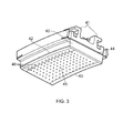
- FIG. 3 shows an isometric view of a typical shroud segment with an abradable coating and effusion cooling.
- the segment has a cast alloy body 40, mounting legs 41 for mounting to the turbine support casing, upstream 42 and downstream 43 edges, a feather or strip seal leakage control groove 44, an abradable surface coating 45, and a plurality of effusion cooling holes 46 which deliver streams of cooling air onto the gas washed surface of the surface coating.
- These streams of cooled air form a protective film on the gas washed surface.
- the film mixes with the hot gas that is adjacent to the surface and progressively heats up as it flows over the surface. This degradation of the film is normally expressed as a "film effectiveness", which typically deteriorates with distance from the holes.
- the holes can be formed as fan shaped openings in order to diffuse the flow as it exits the hole.
- the angle of the holes' feed passages is also an important parameter. In general, a shallower angle of the line of the feed passage relative to the gas washed surface (i.e. a smaller radial angle relative to the engine axis) helps to prevent the film from becoming detached from the surface.
- the present invention is at least partly based on the realisation that shroud segment cooling air can be used to reduce the amount of such leakage flow.
- a first aspect of the present invention provides a shroud segment for a turbine stage of a gas turbine engine, the segment forming an endwall for the working gas annulus of the stage, and providing a close clearance to the tips of a row of turbine blades which sweep across the segment, in use a leakage flow of the working gas passing through the clearance gap between the blade tips and the segment, wherein:
- Configuring the feed passages such that the delivered-air swirl directions of those cooling holes swept by the trailing edges of the blade tips are rotated towards the axial direction of the engine relative to the delivered-air swirl directions of those cooling holes swept by the leading edges of the blade tips can help to better match the delivered-air swirl directions to the local leakage flow directions. This is because, typically, the local direction of the leakage flow at the trailing edges of the blade tips is rotated towards the axial direction of the engine relative to the local direction of the leakage flow at the leading edges of the blade tips.
- the shroud segment may have any one or, to the extent that they are compatible, any combination of the following optional features.
- the line of each feed passage can be defined, relative to the engine axis, by a swirl angle and a radial angle.
- the swirl angle of the line of the feed passage usually determines (e.g. is usually the same as) the swirl angle of the cooling air delivered out of the corresponding cooling hole and hence the swirl direction of that delivered air.
- Configuring a feed passage such that the delivered air opposes the leakage flow of the working gas thus typically involves, for a given position of the cooling hole, setting the swirl angle of the line of the feed passage to provide a desired delivered-air swirl direction.
- each feed passage is configured such that the delivered air has a swirl direction which opposes the local direction of the leakage flow at the respective cooling hole to within at least 30°, and more preferably to within at least 20° or 10°.
- the feed passages may be configured such that the delivered-air swirl directions of the respective cooling holes encountered when moving in an axial direction of the engine from the cooling holes swept by the leading edges of the blade tips to the cooling holes swept by the trailing edges of the blade tips rotate through an angle in the range of from 10° to 70°, and preferably through an angle in the range of from 25° to 55°, for example 30°.
- the portion of the gas-washed surface which is swept by the blade tips may have at least four, and preferably at least six or eight, axially-spaced and circumferentially-extending rows of cooling holes, each row having a respective delivered-air swirl angle (i.e. the delivered-air swirl directions of all the holes of a given row are rotationally symmetric under rotation about the engine axis).
- Having more rows of cooling holes allows the delivered air from each hole to be focused on opposing the leakage flow over a smaller axial distance from each hole. In other words, as variation in direction and strength of the leakage flow is generally narrower over smaller axial distances, each hole can be better "tuned" to the local leakage flow condition.
- cooling holes and respective air feed passages of each row can be configured to produce a fluctuation in the delivered air flow rate encountered when moving in a circumferential direction along the row.
- the holes of at least some neighbouring circumferentially-extending rows may be circumferentially offset. This may assist in allowing the desired angle and spacing of holes, for example by ensuring that the holes do not overlap with each other. Such an arrangement may also assist in providing improved tip sealing over the entire circumference of the shroud.
- the delivered air from the cooling holes can reduce the working gas leakage flow by at least 20%, and preferably by at least 30% or 50%, relative to the working gas leakage flow that would exist in the absence of film cooling of the segment.
- a further aspect of the present invention provides a gas turbine engine having a turbine stage with shroud segments according to the first aspect.
- a method of producing a shroud segment for a turbine stage of a gas turbine engine the segment forming an endwall for the working gas annulus of the stage, and providing a close clearance to the tips of a row of turbine blades which sweep across the segment, in use a leakage flow of the working gas passing through the clearance gap between the blade tips and the segment.
- the method comprises: performing a computational fluid dynamics calculation to predict the leakage flow; and producing a shroud segment as proposed herein, the feed passages being configured such that the delivered air opposes the leakage flow of the working gas, and the delivered-air swirl directions of those cooling holes swept by the trailing edges of the blade tips are rotated towards the axial direction of the engine relative to the delivered-air swirl directions of those cooling holes swept by the leading edges of the blade tips.
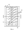
- Figure 4 shows aerodynamic streaklines 50 determined for the gas-washed surface of a conventional shroud segment in the absolute (i.e. nonrotating) frame of reference and for the mainstream flow between passing blades.
- the streaklines originate from cooling holes 51 formed in the gas-washed surface.
- the block arrows Va1, Va2 indicate the direction of the mainstream flow (ignoring radial components of flow) in the inter-blade passage at respectively the entrance and the exit of the passage.
- the cooling holes have passages (indicated by broken lines) which feed air to the holes and are either unswirled relative axial direction of the engine (passages 52) or are at a swirl angle to that direction (passages 53).
- the delivered air forms a cooling film over the gas-washed surface.
- the present invention therefore proposes a change to the shroud segment film cooling configuration to reduce the quantity of leakage flow migrating over the tip of the blade. This can be achieved by configuring the feed passages to the film cooling holes in such a way that the resulting film acts as a "fluid fence" that opposes the progress of the working gas as it tries to leak over the blade tip from the pressure to the suction surface of the blade.
- cooling holes In order to position the cooling holes and configure the feed passages in such a manner that the trajectory of the stream of cooling air is optimised from an over-tip leakage spoiling viewpoint, it is helpful to know the streamlines of the secondary flows at the tip of the blade in both the stationary and rotating frame of reference.
- the cooling holes can then be located in circumferentially extending rows, with the delivered-air swirl direction from each row directly opposing the direction of the local migrating over-tip leakage flow.
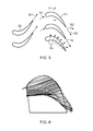
- Figure 5 shows a schematic view of a row of nozzle guide vanes 70 and a following row of rotor blades 71 with arrows indicating: (i) the direction of rotation U of the rotor blades, (ii) the directions of the mainstream flow Va1, Va2 in the absolute frame of reference at respectively the entrance and the exit of the row of rotor blades, and (iii) the corresponding directions Vr1, Vr2 of the mainstream flow in the rotating frame of reference.
- the directions of over-tip leakage flow Vro in the rotating frame of reference are indicated schematically by the dashed arrows.
- Figure 6 shows actual over-tip leakage flow streamlines in the rotating frame of reference from a CFD simulation for a blade.
- Figure 7 shows over-tip leakage flow angles for a typical blade. It will be appreciated that the over-tip leakage flow angles shown in Figure 7 are merely representative of typical flow angles. In the example shown in Figure 7 , the various over-tip leakage angles ( ⁇ ) are shown relative to the direction of travel of the blade (i.e. relative to the local circumferential direction of the shroud). As shown in Figure 7 , the relative flow direction (Vro) becomes more axial as one moves from the leading edge to the trailing edge of the blade, i.e. the over-tip leakage angle ( ⁇ ) increases from the leading edge to the trailing edge.
- the over-tip leakage angle ( ⁇ ) increases from 20 degrees at the leading edge to 70 degrees at the trailing edge. It will be appreciated that other over-tip leakage flow angles may also be observed, depending on, for example, blade design, design of other engine components, tip clearance, and flow conditions. For example, the over-tip leakage angle ( ⁇ ) may be less than 20 degrees at the leading edge, and may be greater than 70 degrees at the trailing edge.
- the rate at which the over-tip leakage angle ( ⁇ ) increases from the leading edge to the trailing edge also increases as the distance from the leading edge increases. As such, for a given distance along the chord of the blade tip, the increase in over-tip leakage angle ( ⁇ ) is greater towards the trailing edge of the blade than towards the leading edge of the blade.
- a velocity triangle can be constructed, as shown in Figure 8 , Vao representing the resultant over-tip leakage flow vector in the absolute frame.
- An equal and opposite vector Vao* represents the magnitude and direction of the local cooling flow that would be needed to prevent the over-tip leakage flow in the stationary frame of reference.
- the shape of the velocity triangle and hence the direction and magnitude of Vao* changes from the front to the rear of the segment as the direction and magnitude of Vro changes from front to rear.
- Vao* is closer to the axial direction of the engine at the trailing edge of the blade than at the leading edge of the blade.
- Figure 9 shows schematically the gas-washed surface 80 of a shroud segment.
- Nine circumferentially extending rows of cooling holes 81 are distributed over that part of the surface which is swept by passing blade tips.
- Respective feed passages feed cooling air to the holes and are configured such that the cooling air delivered out of the holes opposes the direction of the local migrating over-tip leakage flow.
- the swirl directions (indicated by block arrows) of the holes of the different rows are directed along the local Vao*.
- the delivered air swirl angle varies from row to row as Vao* correspondingly varies in the axial direction. If necessary, e.g. to simplify manufacturing, adjacent rows of holes can share the same delivered air swirl angle, although this tends to reduce the ability of at least some of the rows to oppose the leakage flow, i.e. because at least some rows will then provide delivered-air swirl directions which are not so well aligned with the local Vao*.
- any such misalignment is preferably less than about 30°, more preferably less than 20°, more preferably less than 10°, more preferably between 5° and 0°.
- Figure 10 shows schematically the gas-washed surface 80 of a shroud segment similar to that of Figure 9 .
- the holes 81 become increasingly ovoid as they are angled towards the axial direction to oppose the over-tip leakage flow.
- the angle ⁇ shown in Figure 10 represents the angle of the air delivered through the cooling holes 81 (i.e. in the direction Vao*) relative to the direction of travel of the blade (i.e. relative to the local circumferential direction of the shroud).
- the angle of the delivered air becomes more axial in the downstream direction (i.e. towards the region that is swept by the trailing edges of the blades), and thus the angle ⁇ increases in this direction.
- the angle ⁇ is in the range of from 0 degrees to 30 degrees, for example 2 degrees to 15 degrees, for example 5 degrees, at the upstream end of the shroud (i.e. the end of the shroud that is in the proximity of the area washed by the leading edge of the blade).
- the angle ⁇ is in the range of from 15 degrees to 60 degrees, for example 25 degrees to 45 degrees, for example 35 degrees, at the downstream end of the shroud (i.e. the end of the shroud that is in the proximity of the area washed by the trailing edge of the blade).
- the delivered-air angles may be outside these ranges.
- the angle ⁇ increases in the downstream direction.
- the rate at which the angle ⁇ increases also increases in the downstream direction.
- the holes 81 are arranged in circumferential rows.
- the holes may be staggered. This means that circumferentially neighbouring holes may be axially offset.
- An example of such an arrangement is shown in Figure 11 .
- Such an arrangement may provide a better sealing flow around the circumference of the shroud. It may also enable the holes to have the desired angle and spacing, for example by ensuring that neighbouring holes do not interact (i.e. merge into each other).
- FIG. 12 An alternative embodiment is shown in Figure 12 .
- the holes at the upstream end are substantially in-line, i.e. they form circumferential rows, and the holes become increasingly staggered in the downstream direction.
- the holes and feed passages can be sized and/or the hole density varied such that higher delivered-air flow rates are produced at axial positions which have higher leakage flow rates. In this way, the local momentum of the delivered-air flow can be changed. The velocity, and hence momentum of the flow can also be modified by increasing the feed pressure. As increasing the coolant flow rate can be detrimental to turbine efficiency, it is advantageous to only increase delivered-air flow rates where they are needed.
- a circumferentially fluctuating or "pulsing" flow regime can be produced by varying the hole and feed passage size and/or the hole density along the circumferential direction. For example, this could be achieved by changing the hole diameter in alternate holes, or in alternate blocks of 2, 3 or 4 holes, along each circumferential row.
- the pulsing flow to which the blade tips would then be exposed can enhance the opposition to the over-tip leakage of working gas.
- shroud segment cooling can be enhanced by improving convective heat transfer to the cooling air, e.g. by increasing the lengths of the feed passages and/or by directing them at shallower angles to the gas-washed surface (i.e. reducing the radial components of the lines of the passages).
- high-pressure turbine shroud segments are increasingly dependent on high levels of conventional (typically convective) and film cooling in order to maintain acceptable component metal and coating temperatures.
- conventional (typically convective) and film cooling in order to maintain acceptable component metal and coating temperatures.
- the strong secondary flow field set up particularly by upstream NGV aerofoils, combined with the passing rotor blade tips, has a destructive effect on film cooling effectiveness. Sacrificing already poor film cooling effectiveness in order to reduce rotor blade over-tip leakage and associated mixing losses (particularly in the vicinity of the late suction surface, where mixing losses tend to be most detrimental) can provide operational benefits such as improved stage efficiency and ultimately specific fuel consumption.
Landscapes
- Engineering & Computer Science (AREA)
- Mechanical Engineering (AREA)
- General Engineering & Computer Science (AREA)
- Turbine Rotor Nozzle Sealing (AREA)
Abstract
Description
- The present invention relates to a shroud segment for a turbine stage of a gas turbine engine
- With reference to
Figure 1 , a ducted fan gas turbine engine generally indicated at 10 has a principal and rotational axis X-X. The engine comprises, in axial flow series, anair intake 11, apropulsive fan 12, anintermediate pressure compressor 13, a high-pressure compressor 14,combustion equipment 15, a high-pressure turbine 16, and intermediate-pressure turbine 17, a low-pressure turbine 18 and a coreengine exhaust nozzle 19. Anacelle 21 generally surrounds theengine 10 and defines theintake 11, abypass duct 22 and abypass exhaust nozzle 23. - The
gas turbine engine 10 works in a conventional manner so that air entering theintake 11 is accelerated by thefan 12 to produce two air flows: a first air flow A into theintermediate pressure compressor 14 and a second air flow B which passes through thebypass duct 22 to provide propulsive thrust. Theintermediate pressure compressor 13 compresses the air flow A directed into it before delivering that air to thehigh pressure compressor 14 where further compression takes place. - The compressed air exhausted from the high-
pressure compressor 14 is directed into thecombustion equipment 15 where it is mixed with fuel and the mixture combusted. The resultant hot combustion products then expand through, and thereby drive the high, intermediate and low-pressure turbines nozzle 19 to provide additional propulsive thrust. The high, intermediate and low-pressure turbines respectively drive the high andintermediate pressure compressors fan 12 by suitable interconnecting shafts. - The performance of gas turbine engines, whether measured in terms of efficiency or specific output, is improved by increasing the turbine gas temperature. It is therefore desirable to operate the turbines at the highest possible temperatures. For any engine cycle compression ratio or bypass ratio, increasing the turbine entry gas temperature produces more specific thrust (e.g. engine thrust per unit of air mass flow). However as turbine entry temperatures increase, the life of an un-cooled turbine falls, necessitating the development of better materials and the introduction of internal air cooling.
- In modern engines, the high-pressure turbine gas temperatures are hotter than the melting point of the material of the blades and vanes, necessitating internal air cooling of these airfoil components. During its passage through the engine, the mean temperature of the gas stream decreases as power is extracted. Therefore the need to cool the static and rotary parts of the engine structure decreases as the gas moves from the high-pressure stage(s), through the intermediate-pressure and low-pressure stages, and towards the exit nozzle.
-
Figure 2 shows an isometric view of a typical single stage cooled turbine. Cooling air flows are indicated by arrows. - Internal convection and external films are the prime methods of cooling the gas path components - airfoils, platforms, shrouds and shroud segments etc. High-pressure turbine nozzle guide vanes 31 (NGVs) consume the greatest amount of cooling air on high temperature engines. High-
pressure blades 32 typically use about half of the NGV flow. The intermediate-pressure and low-pressure stages downstream of the HP turbine use progressively less cooling air. - The high-pressure turbine airfoils are cooled by using high pressure air from the compressor that has by-passed the combustor and is therefore relatively cool compared to the gas temperature. Typical cooling air temperatures are between 800 and 1000 K, while gas temperatures can be in excess of 2100 K.
- The cooling air from the compressor that is used to cool the hot turbine components is not used fully to extract work from the turbine. Therefore, as extracting coolant flow has an adverse effect on the engine operating efficiency, it is important to use the cooling air effectively.
- Ever increasing gas temperature levels combined with a drive towards flatter combustion radial profiles, in the interests of reduced combustor emissions, have resulted in an increase in local gas temperature experienced by the working gas annulus endwalls, which include
NGV platforms 33,blade platforms 34 and shroud segments 35 (also known as shroud liners). However, the flow of air that is used to cool these endwalls can be highly detrimental to the turbine efficiency. This is due to the high mixing losses attributed to these cooling flows when they are returned to the mainstream working gas path flow. - One option is to cool the platforms and shroud segments by an impingement flow of cooling air on the back surface of the gas washed wall of the component. For example, a perforated plate spaced from the gas washed wall and supported by pedestals can form impinging jets, and the spent coolant can then flow back into the working gas path at the rear edges of the component. Unfortunately, limited numbers of impingement jets can produce non uniform heat transfer distributions, and the cross flow from spent coolant can reduce the effectiveness of the impingement jets at the more downstream locations of the component. In addition, the need to keep the coolant pressure at a level above that in the working gas path reduces the allowable pressure drop across the impingement jets, and hence the associated heat transfer levels.
- Thus, in the case of shroud segments, there has been a move towards the use of abradable coatings that provide a thermal insulating barrier on the gas washed surface of the segment. The corresponding blade tips may have abrasive coatings attached in order to facilitate the cutting of a track into the abradable coating. These coatings have proved effective at reducing the heat flux into the segments. However, their low thermal conductivities introduce a high thermal gradient across the thickness of the coating. Consequently the gas washed surface becomes very hot, and if not protected can increase to a temperature exceeding the sintering temperature limit of the coating material. Similarly, the bond coat that typically attaches the abradable coating to the segment also needs to be kept below a certain temperature to prevent the interface between the coating and the bond coat alloy from oxidizing and prematurely shedding the coating.
- In an attempt to reduce the temperature of the gas washed surface of these coatings, a film of cooled air can be provided between the hot working gas and the coating. This can be achieved by the introduction of effusion cooling onto the surface of the segment.
Figure 3 shows an isometric view of a typical shroud segment with an abradable coating and effusion cooling. The segment has acast alloy body 40, mountinglegs 41 for mounting to the turbine support casing, upstream 42 and downstream 43 edges, a feather or strip sealleakage control groove 44, anabradable surface coating 45, and a plurality ofeffusion cooling holes 46 which deliver streams of cooling air onto the gas washed surface of the surface coating. These streams of cooled air form a protective film on the gas washed surface. However, the film mixes with the hot gas that is adjacent to the surface and progressively heats up as it flows over the surface. This degradation of the film is normally expressed as a "film effectiveness", which typically deteriorates with distance from the holes. - To try to achieve a high level of film effectiveness, it is conventional to introduce the cooling air onto the surface with a low momentum in order to match the momentum of the gas in contact with the wall. If the blowing rate of the film is too high then the film will blow off the surface and mixing between the gas and coolant will be encouraged. The holes can be formed as fan shaped openings in order to diffuse the flow as it exits the hole. The angle of the holes' feed passages is also an important parameter. In general, a shallower angle of the line of the feed passage relative to the gas washed surface (i.e. a smaller radial angle relative to the engine axis) helps to prevent the film from becoming detached from the surface.
- Although the gas washed surface of a shroud segment has a close clearance to the tips of the turbine blades, a leakage flow of working gas nonetheless passes through the gap between the blade tips and the segment. This leakage flow is detrimental to engine efficiency, and also sets up a pressure gradient that is a destructive influence on the cooling film. The present invention is at least partly based on the realisation that shroud segment cooling air can be used to reduce the amount of such leakage flow.
- Thus a first aspect of the present invention provides a shroud segment for a turbine stage of a gas turbine engine, the segment forming an endwall for the working gas annulus of the stage, and providing a close clearance to the tips of a row of turbine blades which sweep across the segment, in use a leakage flow of the working gas passing through the clearance gap between the blade tips and the segment, wherein:
- the segment has a plurality of cooling holes and respective air feed passages for the cooling holes, the cooling holes being distributed over that part of the gas-washed surface of the segment which is swept by the blade tips, the cooling holes delivering, in use, cooling air which spreads over the gas-washed surface, and the feed passages being configured such that the delivered air opposes the leakage flow of the working gas; and
- the feed passages are configured such that the delivered-air swirl directions of those cooling holes swept by the trailing edges of the blade tips are rotated towards the axial direction of the engine relative to the delivered-air swirl directions of those cooling holes swept by the leading edges of the blade tips.
- Although the opposition to the leakage flow may have a detrimental effect on the film cooling effectiveness of the segment, this disadvantage can be more than offset by efficiency gains associated with a reduced leakage flow. Indeed, as the leakage flow can itself be a cause of film disruption, a reduced film effectiveness may in any event be acceptable. Further, it may be possible to compensate for any loss in film effectiveness by increasing convective heat transfer to the cooling air before it exhausts from the holes.
- Configuring the feed passages such that the delivered-air swirl directions of those cooling holes swept by the trailing edges of the blade tips are rotated towards the axial direction of the engine relative to the delivered-air swirl directions of those cooling holes swept by the leading edges of the blade tips can help to better match the delivered-air swirl directions to the local leakage flow directions. This is because, typically, the local direction of the leakage flow at the trailing edges of the blade tips is rotated towards the axial direction of the engine relative to the local direction of the leakage flow at the leading edges of the blade tips.
- The shroud segment may have any one or, to the extent that they are compatible, any combination of the following optional features.
- The line of each feed passage can be defined, relative to the engine axis, by a swirl angle and a radial angle. The swirl angle of the line of the feed passage usually determines (e.g. is usually the same as) the swirl angle of the cooling air delivered out of the corresponding cooling hole and hence the swirl direction of that delivered air. Configuring a feed passage such that the delivered air opposes the leakage flow of the working gas thus typically involves, for a given position of the cooling hole, setting the swirl angle of the line of the feed passage to provide a desired delivered-air swirl direction.
- Preferably, each feed passage is configured such that the delivered air has a swirl direction which opposes the local direction of the leakage flow at the respective cooling hole to within at least 30°, and more preferably to within at least 20° or 10°.
- The feed passages may be configured such that the delivered-air swirl directions of the respective cooling holes encountered when moving in an axial direction of the engine from the cooling holes swept by the leading edges of the blade tips to the cooling holes swept by the trailing edges of the blade tips rotate through an angle in the range of from 10° to 70°, and preferably through an angle in the range of from 25° to 55°, for example 30°.
- The portion of the gas-washed surface which is swept by the blade tips may have at least four, and preferably at least six or eight, axially-spaced and circumferentially-extending rows of cooling holes, each row having a respective delivered-air swirl angle (i.e. the delivered-air swirl directions of all the holes of a given row are rotationally symmetric under rotation about the engine axis). Having more rows of cooling holes allows the delivered air from each hole to be focused on opposing the leakage flow over a smaller axial distance from each hole. In other words, as variation in direction and strength of the leakage flow is generally narrower over smaller axial distances, each hole can be better "tuned" to the local leakage flow condition. In this way, increased numbers of rows of cooling holes can provide a more effective opposition to the overall leakage flow. The cooling holes and respective air feed passages of each row can be configured to produce a fluctuation in the delivered air flow rate encountered when moving in a circumferential direction along the row.
- Optionally, the holes of at least some neighbouring circumferentially-extending rows may be circumferentially offset. This may assist in allowing the desired angle and spacing of holes, for example by ensuring that the holes do not overlap with each other. Such an arrangement may also assist in providing improved tip sealing over the entire circumference of the shroud.
- Typically, the delivered air from the cooling holes can reduce the working gas leakage flow by at least 20%, and preferably by at least 30% or 50%, relative to the working gas leakage flow that would exist in the absence of film cooling of the segment.
- A further aspect of the present invention provides a gas turbine engine having a turbine stage with shroud segments according to the first aspect.
- According to an aspect of the invention, there is provided a method of producing a shroud segment for a turbine stage of a gas turbine engine, the segment forming an endwall for the working gas annulus of the stage, and providing a close clearance to the tips of a row of turbine blades which sweep across the segment, in use a leakage flow of the working gas passing through the clearance gap between the blade tips and the segment. The method comprises: performing a computational fluid dynamics calculation to predict the leakage flow; and producing a shroud segment as proposed herein, the feed passages being configured such that the delivered air opposes the leakage flow of the working gas, and the delivered-air swirl directions of those cooling holes swept by the trailing edges of the blade tips are rotated towards the axial direction of the engine relative to the delivered-air swirl directions of those cooling holes swept by the leading edges of the blade tips.
- Embodiments of the invention will now be described by way of example with reference to the accompanying drawings in which:
-
Figure 1 shows a schematic longitudinal cross-section through a ducted fan gas turbine engine; -
Figure 2 shows an isometric view of a typical single stage cooled turbine; -
Figure 3 shows an isometric view of a typical shroud segment with an abradable coating and effusion cooling; -
Figure 4 shows aerodynamic streaklines determined for the gas-washed surface of a conventional shroud segment in the absolute frame of reference and for the mainstream flow between passing blades; -
Figure 5 shows a schematic view of a row of nozzle guide vanes and a following row of rotor blades; -
Figure 6 shows over-tip leakage flow streamlines in the rotating frame of reference from a CFD simulation for a blade; -
Figure 7 shows a schematic of a rotor blade showing typical gas leakage flow angles in the relative frame of reference; -
Figure 8 shows a velocity triangle; -
Figure 9 shows schematically the gas-washed surface of a shroud segment having cooling holes with feed passage whose swirl angles are aligned with the swirl direction of the local over-tip leakage flow; -
Figure 10 also shows schematically the gas-washed surface of a shroud segment having cooling holes with feed passage whose swirl angles are aligned with the swirl direction of the local over-tip leakage flow; -
Figure 11 shows schematically the gas-washed surface of a shroud segment similar to that ofFigure 10 , but with a staggered hole arrangement; and -
Figure 12 shows schematically the gas-washed surface of a shroud segment similar to that ofFigures 11 and 12 , but with the hole arrangement changing progressively from in-line to staggered. -
Figure 4 showsaerodynamic streaklines 50 determined for the gas-washed surface of a conventional shroud segment in the absolute (i.e. nonrotating) frame of reference and for the mainstream flow between passing blades. The streaklines originate from coolingholes 51 formed in the gas-washed surface. The block arrows Va1, Va2 indicate the direction of the mainstream flow (ignoring radial components of flow) in the inter-blade passage at respectively the entrance and the exit of the passage. The cooling holes have passages (indicated by broken lines) which feed air to the holes and are either unswirled relative axial direction of the engine (passages 52) or are at a swirl angle to that direction (passages 53). The delivered air forms a cooling film over the gas-washed surface. - Unfortunately, when introducing films on to the gas washed surfaces of shroud segments, the effectiveness of the films is dependant on the strength of the secondary flows, driven substantially by the upstream NGV aerofoil and endwall geometry. Another important factor is the presence of the rotor blade tips which continuously wipe away newly formed films, preventing the establishment of traditional film trails that progressively diminish with distance from the hole. Thus, if it is possible for the gas temperature to be accommodated with less effective film coverage (e.g. by relying more heavily on convective heat picked up by the cooling air in the feed passages) then film performance can be traded for reduced blade over-tip leakage. This in turn can lead to a stage efficiency improvement resulting from reduced over-tip losses and reduced blade tip cooling requirements.
- The present invention therefore proposes a change to the shroud segment film cooling configuration to reduce the quantity of leakage flow migrating over the tip of the blade. This can be achieved by configuring the feed passages to the film cooling holes in such a way that the resulting film acts as a "fluid fence" that opposes the progress of the working gas as it tries to leak over the blade tip from the pressure to the suction surface of the blade.
- In order to position the cooling holes and configure the feed passages in such a manner that the trajectory of the stream of cooling air is optimised from an over-tip leakage spoiling viewpoint, it is helpful to know the streamlines of the secondary flows at the tip of the blade in both the stationary and rotating frame of reference. The cooling holes can then be located in circumferentially extending rows, with the delivered-air swirl direction from each row directly opposing the direction of the local migrating over-tip leakage flow.
-
Figure 5 shows a schematic view of a row ofnozzle guide vanes 70 and a following row ofrotor blades 71 with arrows indicating: (i) the direction of rotation U of the rotor blades, (ii) the directions of the mainstream flow Va1, Va2 in the absolute frame of reference at respectively the entrance and the exit of the row of rotor blades, and (iii) the corresponding directions Vr1, Vr2 of the mainstream flow in the rotating frame of reference. The directions of over-tip leakage flow Vro in the rotating frame of reference are indicated schematically by the dashed arrows. For comparison,Figure 6 shows actual over-tip leakage flow streamlines in the rotating frame of reference from a CFD simulation for a blade. -
Figure 7 shows over-tip leakage flow angles for a typical blade. It will be appreciated that the over-tip leakage flow angles shown inFigure 7 are merely representative of typical flow angles. In the example shown inFigure 7 , the various over-tip leakage angles (ø) are shown relative to the direction of travel of the blade (i.e. relative to the local circumferential direction of the shroud). As shown inFigure 7 , the relative flow direction (Vro) becomes more axial as one moves from the leading edge to the trailing edge of the blade, i.e. the over-tip leakage angle (ø) increases from the leading edge to the trailing edge. - In the example of
Figure 7 , the over-tip leakage angle (ø) increases from 20 degrees at the leading edge to 70 degrees at the trailing edge. It will be appreciated that other over-tip leakage flow angles may also be observed, depending on, for example, blade design, design of other engine components, tip clearance, and flow conditions. For example, the over-tip leakage angle (ø) may be less than 20 degrees at the leading edge, and may be greater than 70 degrees at the trailing edge. - In the example of
Figure 7 , the rate at which the over-tip leakage angle (ø) increases from the leading edge to the trailing edge also increases as the distance from the leading edge increases. As such, for a given distance along the chord of the blade tip, the increase in over-tip leakage angle (ø) is greater towards the trailing edge of the blade than towards the leading edge of the blade. - For each Vro, a velocity triangle can be constructed, as shown in
Figure 8 , Vao representing the resultant over-tip leakage flow vector in the absolute frame. An equal and opposite vector Vao* represents the magnitude and direction of the local cooling flow that would be needed to prevent the over-tip leakage flow in the stationary frame of reference. The shape of the velocity triangle and hence the direction and magnitude of Vao* changes from the front to the rear of the segment as the direction and magnitude of Vro changes from front to rear. In general, Vao* is closer to the axial direction of the engine at the trailing edge of the blade than at the leading edge of the blade. -
Figure 9 shows schematically the gas-washedsurface 80 of a shroud segment. Nine circumferentially extending rows of cooling holes 81 are distributed over that part of the surface which is swept by passing blade tips. Respective feed passages feed cooling air to the holes and are configured such that the cooling air delivered out of the holes opposes the direction of the local migrating over-tip leakage flow. The swirl directions (indicated by block arrows) of the holes of the different rows are directed along the local Vao*. - Thus the delivered air swirl angle varies from row to row as Vao* correspondingly varies in the axial direction. If necessary, e.g. to simplify manufacturing, adjacent rows of holes can share the same delivered air swirl angle, although this tends to reduce the ability of at least some of the rows to oppose the leakage flow, i.e. because at least some rows will then provide delivered-air swirl directions which are not so well aligned with the local Vao*.
- If the trajectory of the delivered coolant flow is not aligned with and in a contrary direction to the blade over-tip leakage flow, then only a component of its velocity will oppose the migrating flow. Thus any such misalignment is preferably less than about 30°, more preferably less than 20°, more preferably less than 10°, more preferably between 5° and 0°.
-
Figure 10 shows schematically the gas-washedsurface 80 of a shroud segment similar to that ofFigure 9 . InFigure 10 , theholes 81 become increasingly ovoid as they are angled towards the axial direction to oppose the over-tip leakage flow. The angle Ω shown inFigure 10 represents the angle of the air delivered through the cooling holes 81 (i.e. in the direction Vao*) relative to the direction of travel of the blade (i.e. relative to the local circumferential direction of the shroud). - In the example shown in
Figure 10 , the angle of the delivered air becomes more axial in the downstream direction (i.e. towards the region that is swept by the trailing edges of the blades), and thus the angle Ω increases in this direction. Typically, the angle Ω is in the range of from 0 degrees to 30 degrees, for example 2 degrees to 15 degrees, for example 5 degrees, at the upstream end of the shroud (i.e. the end of the shroud that is in the proximity of the area washed by the leading edge of the blade). Typically, the angle Ω is in the range of from 15 degrees to 60 degrees, for example 25 degrees to 45 degrees, for example 35 degrees, at the downstream end of the shroud (i.e. the end of the shroud that is in the proximity of the area washed by the trailing edge of the blade). However, in other embodiments, the delivered-air angles may be outside these ranges. - As noted above, in the described embodiments, the angle Ω increases in the downstream direction. In some embodiments, the rate at which the angle Ω increases also increases in the downstream direction.
- In the embodiments shown in
Figures 9 and10 , theholes 81 are arranged in circumferential rows. However, in alternative embodiments, the holes may be staggered. This means that circumferentially neighbouring holes may be axially offset. An example of such an arrangement is shown inFigure 11 . Such an arrangement may provide a better sealing flow around the circumference of the shroud. It may also enable the holes to have the desired angle and spacing, for example by ensuring that neighbouring holes do not interact (i.e. merge into each other). - An alternative embodiment is shown in
Figure 12 . In this embodiment, the holes at the upstream end are substantially in-line, i.e. they form circumferential rows, and the holes become increasingly staggered in the downstream direction. - It will be appreciated that any suitable arrangement of holes could be used. It will also be appreciated that the features of the
holes 81 discussed herein in relation toFigures 10 ,11 and 12 may apply to all embodiments, such as that shown inFigure 9 . - The holes and feed passages can be sized and/or the hole density varied such that higher delivered-air flow rates are produced at axial positions which have higher leakage flow rates. In this way, the local momentum of the delivered-air flow can be changed. The velocity, and hence momentum of the flow can also be modified by increasing the feed pressure. As increasing the coolant flow rate can be detrimental to turbine efficiency, it is advantageous to only increase delivered-air flow rates where they are needed.
- A circumferentially fluctuating or "pulsing" flow regime can be produced by varying the hole and feed passage size and/or the hole density along the circumferential direction. For example, this could be achieved by changing the hole diameter in alternate holes, or in alternate blocks of 2, 3 or 4 holes, along each circumferential row. The pulsing flow to which the blade tips would then be exposed can enhance the opposition to the over-tip leakage of working gas.
- Although the film cooling effectiveness is somewhat compromised transiently between passing blade tips by aligning delivered air swirl directions along the direction of the local Vao*, the adverse pressure gradient generated by the secondary flow from upstream NGVs and endwall geometries can anyway be a destructive influence on a cooling film, causing it to become detached from the gas washed surface. Thus it has been found that it is possible to use spent cooling air to reduce the quantity of hot gas leaking over the blade tips, without compromising the thermal integrity of the shroud segment. Reducing the over-tip leakage flow locally reduces the mixed out temperature of the fluid migrating over the blade tip, which has a beneficial effect both thermally and aerodynamically. In addition, the blade tip can require less coolant to maintain its integrity. If necessary, shroud segment cooling can be enhanced by improving convective heat transfer to the cooling air, e.g. by increasing the lengths of the feed passages and/or by directing them at shallower angles to the gas-washed surface (i.e. reducing the radial components of the lines of the passages).
- In summary, high-pressure turbine shroud segments are increasingly dependent on high levels of conventional (typically convective) and film cooling in order to maintain acceptable component metal and coating temperatures. However, the strong secondary flow field set up particularly by upstream NGV aerofoils, combined with the passing rotor blade tips, has a destructive effect on film cooling effectiveness. Sacrificing already poor film cooling effectiveness in order to reduce rotor blade over-tip leakage and associated mixing losses (particularly in the vicinity of the late suction surface, where mixing losses tend to be most detrimental) can provide operational benefits such as improved stage efficiency and ultimately specific fuel consumption.
- While the invention has been described in conjunction with the exemplary embodiments described above, many equivalent modifications and variations will be apparent to those skilled in the art when given this disclosure. Accordingly, the exemplary embodiments of the invention set forth above are considered to be illustrative and not limiting. Various changes to the described embodiments may be made without departing from the scope of the invention.
Claims (8)
- A shroud segment for a turbine stage of a gas turbine engine, the segment forming an endwall for the working gas annulus of the stage, and providing a close clearance to the tips of a row of turbine blades which sweep across the segment, in use a leakage flow of the working gas passing through the clearance gap between the blade tips and the segment, wherein:the segment has a plurality of cooling holes (81) and respective air feed passages for the cooling holes, the cooling holes being distributed over that part of the gas-washed surface (80) of the segment which is swept by the blade tips, the cooling holes delivering, in use, cooling air which spreads over the gas-washed surface, and the feed passages being configured such that the delivered air opposes the leakage flow of the working gas; andthe feed passages are configured such that the delivered-air swirl directions of those cooling holes swept by the trailing edges of the blade tips are rotated towards the axial direction of the engine relative to the delivered-air swirl directions of those cooling holes swept by the leading edges of the blade tips.
- A shroud segment according to claim 1, wherein each feed passage is configured such that the delivered air has a swirl direction which opposes the local direction of the leakage flow at the hole to within at least 30°.
- A shroud segment according to any one of the previous claims, wherein the feed passages are configured such that the delivered-air swirl directions of the respective cooling holes encountered when moving in an axial direction of the engine from the cooling holes swept by the leading edges of the blade tips to the cooling holes swept by the trailing edges of the blade tips rotate through an angle in the range of from 10° to 70°.
- A shroud segment according to any one of the previous claims, wherein the portion of the gas-washed surface which is swept by the blade tips has at least four axially-spaced and circumferentially-extending rows of cooling holes, each row having a respective delivered-air swirl angle.
- A shroud segment according to claim 4, wherein the holes of at least some neighbouring circumferentially-extending rows are circumferentially offset.
- A shroud segment according to any one of the previous claims, wherein the delivered air from the cooling holes reduces the working gas leakage flow by at least 20% relative to the working gas leakage flow that would exist in the absence of film cooling of the segment.
- A gas turbine engine having a turbine stage with shroud segments according to any one of the previous claims.
- A method of producing a shroud segment for a turbine stage of a gas turbine engine, the segment forming an endwall for the working gas annulus of the stage, and providing a close clearance to the tips of a row of turbine blades which sweep across the segment, in use a leakage flow of the working gas passing through the clearance gap between the blade tips and the segment, wherein the method comprises:performing a computational fluid dynamics calculation to predict the leakage flow; andproducing a shroud segment according to any one of claims 1 to 6, the feed passages being configured such that the delivered air opposes the leakage flow of the working gas, and the delivered-air swirl directions of those cooling holes swept by the trailing edges of the blade tips are rotated towards the axial direction of the engine relative to the delivered-air swirl directions of those cooling holes swept by the leading edges of the blade tips.
Applications Claiming Priority (1)
| Application Number | Priority Date | Filing Date | Title |
|---|---|---|---|
| GBGB1012783.5A GB201012783D0 (en) | 2010-07-30 | 2010-07-30 | Turbine stage shroud segment |
Publications (3)
| Publication Number | Publication Date |
|---|---|
| EP2412934A2 true EP2412934A2 (en) | 2012-02-01 |
| EP2412934A3 EP2412934A3 (en) | 2017-12-27 |
| EP2412934B1 EP2412934B1 (en) | 2019-03-13 |
Family
ID=42799322
Family Applications (1)
| Application Number | Title | Priority Date | Filing Date |
|---|---|---|---|
| EP11172840.8A Not-in-force EP2412934B1 (en) | 2010-07-30 | 2011-07-06 | Turbine stage shroud segment |
Country Status (4)
| Country | Link |
|---|---|
| US (1) | US8714918B2 (en) |
| EP (1) | EP2412934B1 (en) |
| JP (1) | JP2012047171A (en) |
| GB (1) | GB201012783D0 (en) |
Cited By (1)
| Publication number | Priority date | Publication date | Assignee | Title |
|---|---|---|---|---|
| US11686208B2 (en) | 2020-02-06 | 2023-06-27 | Rolls-Royce Corporation | Abrasive coating for high-temperature mechanical systems |
Families Citing this family (8)
| Publication number | Priority date | Publication date | Assignee | Title |
|---|---|---|---|---|
| US10018068B2 (en) * | 2015-01-13 | 2018-07-10 | United Technologies Corporation | Blade outer air seal with cooling holes |
| RU2706210C2 (en) | 2016-01-25 | 2019-11-14 | Ансалдо Энерджиа Свитзерлэнд Аг | Stator thermal shield for gas turbine, gas turbine with such stator thermal shield and stator thermal shield cooling method |
| US10221859B2 (en) | 2016-02-08 | 2019-03-05 | General Electric Company | Turbine engine compressor blade |
| US10619504B2 (en) * | 2017-10-31 | 2020-04-14 | United Technologies Corporation | Gas turbine engine blade outer air seal cooling hole configuration |
| US10907501B2 (en) | 2018-08-21 | 2021-02-02 | General Electric Company | Shroud hanger assembly cooling |
| KR102158298B1 (en) * | 2019-02-21 | 2020-09-21 | 두산중공업 주식회사 | Turbine blade, turbine including the same |
| US12123308B2 (en) | 2022-03-23 | 2024-10-22 | General Electric Company | Clearance control system for a gas turbine engine |
| GB202212532D0 (en) * | 2022-08-30 | 2022-10-12 | Rolls Royce Plc | Turbine shroud segment and its manufacture |
Family Cites Families (12)
| Publication number | Priority date | Publication date | Assignee | Title |
|---|---|---|---|---|
| US2685429A (en) | 1950-01-31 | 1954-08-03 | Gen Electric | Dynamic sealing arrangement for turbomachines |
| US4311431A (en) | 1978-11-08 | 1982-01-19 | Teledyne Industries, Inc. | Turbine engine with shroud cooling means |
| US4526226A (en) | 1981-08-31 | 1985-07-02 | General Electric Company | Multiple-impingement cooled structure |
| JPS6345402A (en) * | 1986-08-11 | 1988-02-26 | Nagasu Hideo | Fluid machine |
| US5169287A (en) | 1991-05-20 | 1992-12-08 | General Electric Company | Shroud cooling assembly for gas turbine engine |
| WO1994012775A1 (en) | 1992-11-24 | 1994-06-09 | United Technologies Corporation | Coolable outer air seal assembly for a turbine |
| US5649806A (en) | 1993-11-22 | 1997-07-22 | United Technologies Corporation | Enhanced film cooling slot for turbine blade outer air seals |
| US6139257A (en) * | 1998-03-23 | 2000-10-31 | General Electric Company | Shroud cooling assembly for gas turbine engine |
| US6196792B1 (en) | 1999-01-29 | 2001-03-06 | General Electric Company | Preferentially cooled turbine shroud |
| US6354795B1 (en) | 2000-07-27 | 2002-03-12 | General Electric Company | Shroud cooling segment and assembly |
| US7387488B2 (en) | 2005-08-05 | 2008-06-17 | General Electric Company | Cooled turbine shroud |
| US7296967B2 (en) * | 2005-09-13 | 2007-11-20 | General Electric Company | Counterflow film cooled wall |
-
2010
- 2010-07-30 GB GBGB1012783.5A patent/GB201012783D0/en not_active Ceased
-
2011
- 2011-07-06 EP EP11172840.8A patent/EP2412934B1/en not_active Not-in-force
- 2011-07-06 US US13/177,151 patent/US8714918B2/en not_active Expired - Fee Related
- 2011-08-01 JP JP2011168612A patent/JP2012047171A/en not_active Withdrawn
Non-Patent Citations (1)
| Title |
|---|
| None |
Cited By (1)
| Publication number | Priority date | Publication date | Assignee | Title |
|---|---|---|---|---|
| US11686208B2 (en) | 2020-02-06 | 2023-06-27 | Rolls-Royce Corporation | Abrasive coating for high-temperature mechanical systems |
Also Published As
| Publication number | Publication date |
|---|---|
| GB201012783D0 (en) | 2010-09-15 |
| JP2012047171A (en) | 2012-03-08 |
| EP2412934A3 (en) | 2017-12-27 |
| US20120027576A1 (en) | 2012-02-02 |
| EP2412934B1 (en) | 2019-03-13 |
| US8714918B2 (en) | 2014-05-06 |
Similar Documents
| Publication | Publication Date | Title |
|---|---|---|
| EP2412934B1 (en) | Turbine stage shroud segment | |
| EP2980360B1 (en) | Gas turbine engine end-wall component | |
| US9206697B2 (en) | Aerofoil cooling | |
| EP2825748B1 (en) | Cooling channel for a gas turbine engine and gas turbine engine | |
| JP5947524B2 (en) | Turbomachine vane and method for cooling turbomachine vane | |
| EP2492454B1 (en) | Endwall component for a turbine stage of a gas turbine engine | |
| US9528443B2 (en) | Effusion cooled shroud segment with an abradable system | |
| US20110259015A1 (en) | Tangential Combustor | |
| US9512782B2 (en) | Gas turbine engine end-wall component | |
| US9382811B2 (en) | Aerofoil cooling arrangement | |
| EP3406852B1 (en) | Turbine component with tip film cooling and method of cooling | |
| CN110725718A (en) | Turbine engine component with cooling holes | |
| US20160341049A1 (en) | Cooling of turbine blades | |
| US20120057961A1 (en) | Turbine stage shroud segment | |
| US9376918B2 (en) | Aerofoil cooling arrangement | |
| US20230417150A1 (en) | Augmented cooling for tip clearance optimization | |
| EP3184736B1 (en) | Angled heat transfer pedestal | |
| EP2604795B1 (en) | Aerofoil blade or vane | |
| EP2378071A1 (en) | Turbine assembly having cooling arrangement and method of cooling |
Legal Events
| Date | Code | Title | Description |
|---|---|---|---|
| AK | Designated contracting states |
Kind code of ref document: A2 Designated state(s): AL AT BE BG CH CY CZ DE DK EE ES FI FR GB GR HR HU IE IS IT LI LT LU LV MC MK MT NL NO PL PT RO RS SE SI SK SM TR |
|
| AX | Request for extension of the european patent |
Extension state: BA ME |
|
| PUAI | Public reference made under article 153(3) epc to a published international application that has entered the european phase |
Free format text: ORIGINAL CODE: 0009012 |
|
| RAP1 | Party data changed (applicant data changed or rights of an application transferred) |
Owner name: ROLLS-ROYCE PLC |
|
| PUAL | Search report despatched |
Free format text: ORIGINAL CODE: 0009013 |
|
| AK | Designated contracting states |
Kind code of ref document: A3 Designated state(s): AL AT BE BG CH CY CZ DE DK EE ES FI FR GB GR HR HU IE IS IT LI LT LU LV MC MK MT NL NO PL PT RO RS SE SI SK SM TR |
|
| AX | Request for extension of the european patent |
Extension state: BA ME |
|
| RIC1 | Information provided on ipc code assigned before grant |
Ipc: F01D 25/12 20060101ALI20171123BHEP Ipc: F01D 11/08 20060101AFI20171123BHEP Ipc: F01D 11/10 20060101ALI20171123BHEP |
|
| STAA | Information on the status of an ep patent application or granted ep patent |
Free format text: STATUS: REQUEST FOR EXAMINATION WAS MADE |
|
| 17P | Request for examination filed |
Effective date: 20180117 |
|
| RBV | Designated contracting states (corrected) |
Designated state(s): AL AT BE BG CH CY CZ DE DK EE ES FI FR GB GR HR HU IE IS IT LI LT LU LV MC MK MT NL NO PL PT RO RS SE SI SK SM TR |
|
| STAA | Information on the status of an ep patent application or granted ep patent |
Free format text: STATUS: EXAMINATION IS IN PROGRESS |
|
| 17Q | First examination report despatched |
Effective date: 20180528 |
|
| GRAP | Despatch of communication of intention to grant a patent |
Free format text: ORIGINAL CODE: EPIDOSNIGR1 |
|
| STAA | Information on the status of an ep patent application or granted ep patent |
Free format text: STATUS: GRANT OF PATENT IS INTENDED |
|
| GRAS | Grant fee paid |
Free format text: ORIGINAL CODE: EPIDOSNIGR3 |
|
| GRAA | (expected) grant |
Free format text: ORIGINAL CODE: 0009210 |
|
| STAA | Information on the status of an ep patent application or granted ep patent |
Free format text: STATUS: THE PATENT HAS BEEN GRANTED |
|
| INTG | Intention to grant announced |
Effective date: 20190117 |
|
| AK | Designated contracting states |
Kind code of ref document: B1 Designated state(s): AL AT BE BG CH CY CZ DE DK EE ES FI FR GB GR HR HU IE IS IT LI LT LU LV MC MK MT NL NO PL PT RO RS SE SI SK SM TR |
|
| REG | Reference to a national code |
Ref country code: GB Ref legal event code: FG4D |
|
| REG | Reference to a national code |
Ref country code: CH Ref legal event code: EP Ref country code: AT Ref legal event code: REF Ref document number: 1107949 Country of ref document: AT Kind code of ref document: T Effective date: 20190315 |
|
| REG | Reference to a national code |
Ref country code: IE Ref legal event code: FG4D |
|
| REG | Reference to a national code |
Ref country code: DE Ref legal event code: R096 Ref document number: 602011057054 Country of ref document: DE |
|
| REG | Reference to a national code |
Ref country code: NL Ref legal event code: MP Effective date: 20190313 |
|
| REG | Reference to a national code |
Ref country code: LT Ref legal event code: MG4D |
|
| PG25 | Lapsed in a contracting state [announced via postgrant information from national office to epo] |
Ref country code: FI Free format text: LAPSE BECAUSE OF FAILURE TO SUBMIT A TRANSLATION OF THE DESCRIPTION OR TO PAY THE FEE WITHIN THE PRESCRIBED TIME-LIMIT Effective date: 20190313 Ref country code: LT Free format text: LAPSE BECAUSE OF FAILURE TO SUBMIT A TRANSLATION OF THE DESCRIPTION OR TO PAY THE FEE WITHIN THE PRESCRIBED TIME-LIMIT Effective date: 20190313 Ref country code: NO Free format text: LAPSE BECAUSE OF FAILURE TO SUBMIT A TRANSLATION OF THE DESCRIPTION OR TO PAY THE FEE WITHIN THE PRESCRIBED TIME-LIMIT Effective date: 20190613 Ref country code: SE Free format text: LAPSE BECAUSE OF FAILURE TO SUBMIT A TRANSLATION OF THE DESCRIPTION OR TO PAY THE FEE WITHIN THE PRESCRIBED TIME-LIMIT Effective date: 20190313 |
|
| PG25 | Lapsed in a contracting state [announced via postgrant information from national office to epo] |
Ref country code: NL Free format text: LAPSE BECAUSE OF FAILURE TO SUBMIT A TRANSLATION OF THE DESCRIPTION OR TO PAY THE FEE WITHIN THE PRESCRIBED TIME-LIMIT Effective date: 20190313 Ref country code: LV Free format text: LAPSE BECAUSE OF FAILURE TO SUBMIT A TRANSLATION OF THE DESCRIPTION OR TO PAY THE FEE WITHIN THE PRESCRIBED TIME-LIMIT Effective date: 20190313 Ref country code: GR Free format text: LAPSE BECAUSE OF FAILURE TO SUBMIT A TRANSLATION OF THE DESCRIPTION OR TO PAY THE FEE WITHIN THE PRESCRIBED TIME-LIMIT Effective date: 20190614 Ref country code: HR Free format text: LAPSE BECAUSE OF FAILURE TO SUBMIT A TRANSLATION OF THE DESCRIPTION OR TO PAY THE FEE WITHIN THE PRESCRIBED TIME-LIMIT Effective date: 20190313 Ref country code: RS Free format text: LAPSE BECAUSE OF FAILURE TO SUBMIT A TRANSLATION OF THE DESCRIPTION OR TO PAY THE FEE WITHIN THE PRESCRIBED TIME-LIMIT Effective date: 20190313 Ref country code: BG Free format text: LAPSE BECAUSE OF FAILURE TO SUBMIT A TRANSLATION OF THE DESCRIPTION OR TO PAY THE FEE WITHIN THE PRESCRIBED TIME-LIMIT Effective date: 20190613 |
|
| REG | Reference to a national code |
Ref country code: AT Ref legal event code: MK05 Ref document number: 1107949 Country of ref document: AT Kind code of ref document: T Effective date: 20190313 |
|
| PG25 | Lapsed in a contracting state [announced via postgrant information from national office to epo] |
Ref country code: EE Free format text: LAPSE BECAUSE OF FAILURE TO SUBMIT A TRANSLATION OF THE DESCRIPTION OR TO PAY THE FEE WITHIN THE PRESCRIBED TIME-LIMIT Effective date: 20190313 Ref country code: IT Free format text: LAPSE BECAUSE OF FAILURE TO SUBMIT A TRANSLATION OF THE DESCRIPTION OR TO PAY THE FEE WITHIN THE PRESCRIBED TIME-LIMIT Effective date: 20190313 Ref country code: CZ Free format text: LAPSE BECAUSE OF FAILURE TO SUBMIT A TRANSLATION OF THE DESCRIPTION OR TO PAY THE FEE WITHIN THE PRESCRIBED TIME-LIMIT Effective date: 20190313 Ref country code: RO Free format text: LAPSE BECAUSE OF FAILURE TO SUBMIT A TRANSLATION OF THE DESCRIPTION OR TO PAY THE FEE WITHIN THE PRESCRIBED TIME-LIMIT Effective date: 20190313 Ref country code: ES Free format text: LAPSE BECAUSE OF FAILURE TO SUBMIT A TRANSLATION OF THE DESCRIPTION OR TO PAY THE FEE WITHIN THE PRESCRIBED TIME-LIMIT Effective date: 20190313 Ref country code: AL Free format text: LAPSE BECAUSE OF FAILURE TO SUBMIT A TRANSLATION OF THE DESCRIPTION OR TO PAY THE FEE WITHIN THE PRESCRIBED TIME-LIMIT Effective date: 20190313 Ref country code: SK Free format text: LAPSE BECAUSE OF FAILURE TO SUBMIT A TRANSLATION OF THE DESCRIPTION OR TO PAY THE FEE WITHIN THE PRESCRIBED TIME-LIMIT Effective date: 20190313 Ref country code: PT Free format text: LAPSE BECAUSE OF FAILURE TO SUBMIT A TRANSLATION OF THE DESCRIPTION OR TO PAY THE FEE WITHIN THE PRESCRIBED TIME-LIMIT Effective date: 20190713 |
|
| PG25 | Lapsed in a contracting state [announced via postgrant information from national office to epo] |
Ref country code: PL Free format text: LAPSE BECAUSE OF FAILURE TO SUBMIT A TRANSLATION OF THE DESCRIPTION OR TO PAY THE FEE WITHIN THE PRESCRIBED TIME-LIMIT Effective date: 20190313 Ref country code: SM Free format text: LAPSE BECAUSE OF FAILURE TO SUBMIT A TRANSLATION OF THE DESCRIPTION OR TO PAY THE FEE WITHIN THE PRESCRIBED TIME-LIMIT Effective date: 20190313 |
|
| REG | Reference to a national code |
Ref country code: DE Ref legal event code: R097 Ref document number: 602011057054 Country of ref document: DE |
|
| PG25 | Lapsed in a contracting state [announced via postgrant information from national office to epo] |
Ref country code: AT Free format text: LAPSE BECAUSE OF FAILURE TO SUBMIT A TRANSLATION OF THE DESCRIPTION OR TO PAY THE FEE WITHIN THE PRESCRIBED TIME-LIMIT Effective date: 20190313 Ref country code: IS Free format text: LAPSE BECAUSE OF FAILURE TO SUBMIT A TRANSLATION OF THE DESCRIPTION OR TO PAY THE FEE WITHIN THE PRESCRIBED TIME-LIMIT Effective date: 20190713 |
|
| PLBE | No opposition filed within time limit |
Free format text: ORIGINAL CODE: 0009261 |
|
| STAA | Information on the status of an ep patent application or granted ep patent |
Free format text: STATUS: NO OPPOSITION FILED WITHIN TIME LIMIT |
|
| PG25 | Lapsed in a contracting state [announced via postgrant information from national office to epo] |
Ref country code: DK Free format text: LAPSE BECAUSE OF FAILURE TO SUBMIT A TRANSLATION OF THE DESCRIPTION OR TO PAY THE FEE WITHIN THE PRESCRIBED TIME-LIMIT Effective date: 20190313 |
|
| 26N | No opposition filed |
Effective date: 20191216 |
|
| PG25 | Lapsed in a contracting state [announced via postgrant information from national office to epo] |
Ref country code: SI Free format text: LAPSE BECAUSE OF FAILURE TO SUBMIT A TRANSLATION OF THE DESCRIPTION OR TO PAY THE FEE WITHIN THE PRESCRIBED TIME-LIMIT Effective date: 20190313 Ref country code: MC Free format text: LAPSE BECAUSE OF FAILURE TO SUBMIT A TRANSLATION OF THE DESCRIPTION OR TO PAY THE FEE WITHIN THE PRESCRIBED TIME-LIMIT Effective date: 20190313 |
|
| REG | Reference to a national code |
Ref country code: CH Ref legal event code: PL |
|
| PG25 | Lapsed in a contracting state [announced via postgrant information from national office to epo] |
Ref country code: TR Free format text: LAPSE BECAUSE OF FAILURE TO SUBMIT A TRANSLATION OF THE DESCRIPTION OR TO PAY THE FEE WITHIN THE PRESCRIBED TIME-LIMIT Effective date: 20190313 |
|
| REG | Reference to a national code |
Ref country code: BE Ref legal event code: MM Effective date: 20190731 |
|
| PG25 | Lapsed in a contracting state [announced via postgrant information from national office to epo] |
Ref country code: BE Free format text: LAPSE BECAUSE OF NON-PAYMENT OF DUE FEES Effective date: 20190731 Ref country code: LU Free format text: LAPSE BECAUSE OF NON-PAYMENT OF DUE FEES Effective date: 20190706 Ref country code: LI Free format text: LAPSE BECAUSE OF NON-PAYMENT OF DUE FEES Effective date: 20190731 Ref country code: CH Free format text: LAPSE BECAUSE OF NON-PAYMENT OF DUE FEES Effective date: 20190731 |
|
| PG25 | Lapsed in a contracting state [announced via postgrant information from national office to epo] |
Ref country code: IE Free format text: LAPSE BECAUSE OF NON-PAYMENT OF DUE FEES Effective date: 20190706 |
|
| PGFP | Annual fee paid to national office [announced via postgrant information from national office to epo] |
Ref country code: GB Payment date: 20200724 Year of fee payment: 10 Ref country code: FR Payment date: 20200728 Year of fee payment: 10 Ref country code: DE Payment date: 20200928 Year of fee payment: 10 |
|
| PG25 | Lapsed in a contracting state [announced via postgrant information from national office to epo] |
Ref country code: CY Free format text: LAPSE BECAUSE OF FAILURE TO SUBMIT A TRANSLATION OF THE DESCRIPTION OR TO PAY THE FEE WITHIN THE PRESCRIBED TIME-LIMIT Effective date: 20190313 |
|
| PG25 | Lapsed in a contracting state [announced via postgrant information from national office to epo] |
Ref country code: MT Free format text: LAPSE BECAUSE OF FAILURE TO SUBMIT A TRANSLATION OF THE DESCRIPTION OR TO PAY THE FEE WITHIN THE PRESCRIBED TIME-LIMIT Effective date: 20190313 Ref country code: HU Free format text: LAPSE BECAUSE OF FAILURE TO SUBMIT A TRANSLATION OF THE DESCRIPTION OR TO PAY THE FEE WITHIN THE PRESCRIBED TIME-LIMIT; INVALID AB INITIO Effective date: 20110706 |
|
| REG | Reference to a national code |
Ref country code: DE Ref legal event code: R119 Ref document number: 602011057054 Country of ref document: DE |
|
| GBPC | Gb: european patent ceased through non-payment of renewal fee |
Effective date: 20210706 |
|
| PG25 | Lapsed in a contracting state [announced via postgrant information from national office to epo] |
Ref country code: GB Free format text: LAPSE BECAUSE OF NON-PAYMENT OF DUE FEES Effective date: 20210706 Ref country code: DE Free format text: LAPSE BECAUSE OF NON-PAYMENT OF DUE FEES Effective date: 20220201 |
|
| PG25 | Lapsed in a contracting state [announced via postgrant information from national office to epo] |
Ref country code: FR Free format text: LAPSE BECAUSE OF NON-PAYMENT OF DUE FEES Effective date: 20210731 |
|
| PG25 | Lapsed in a contracting state [announced via postgrant information from national office to epo] |
Ref country code: MK Free format text: LAPSE BECAUSE OF FAILURE TO SUBMIT A TRANSLATION OF THE DESCRIPTION OR TO PAY THE FEE WITHIN THE PRESCRIBED TIME-LIMIT Effective date: 20190313 |