EP2412923A2 - Rotor cover plate retention - Google Patents
Rotor cover plate retention Download PDFInfo
- Publication number
- EP2412923A2 EP2412923A2 EP20110173345 EP11173345A EP2412923A2 EP 2412923 A2 EP2412923 A2 EP 2412923A2 EP 20110173345 EP20110173345 EP 20110173345 EP 11173345 A EP11173345 A EP 11173345A EP 2412923 A2 EP2412923 A2 EP 2412923A2
- Authority
- EP
- European Patent Office
- Prior art keywords
- finger
- cover plate
- slot
- rotor disk
- flange
- Prior art date
- Legal status (The legal status is an assumption and is not a legal conclusion. Google has not performed a legal analysis and makes no representation as to the accuracy of the status listed.)
- Granted
Links
Images
Classifications
-
- F—MECHANICAL ENGINEERING; LIGHTING; HEATING; WEAPONS; BLASTING
- F01—MACHINES OR ENGINES IN GENERAL; ENGINE PLANTS IN GENERAL; STEAM ENGINES
- F01D—NON-POSITIVE DISPLACEMENT MACHINES OR ENGINES, e.g. STEAM TURBINES
- F01D5/00—Blades; Blade-carrying members; Heating, heat-insulating, cooling or antivibration means on the blades or the members
- F01D5/02—Blade-carrying members, e.g. rotors
- F01D5/08—Heating, heat-insulating or cooling means
- F01D5/081—Cooling fluid being directed on the side of the rotor disc or at the roots of the blades
- F01D5/082—Cooling fluid being directed on the side of the rotor disc or at the roots of the blades on the side of the rotor disc
-
- F—MECHANICAL ENGINEERING; LIGHTING; HEATING; WEAPONS; BLASTING
- F01—MACHINES OR ENGINES IN GENERAL; ENGINE PLANTS IN GENERAL; STEAM ENGINES
- F01D—NON-POSITIVE DISPLACEMENT MACHINES OR ENGINES, e.g. STEAM TURBINES
- F01D5/00—Blades; Blade-carrying members; Heating, heat-insulating, cooling or antivibration means on the blades or the members
- F01D5/02—Blade-carrying members, e.g. rotors
- F01D5/06—Rotors for more than one axial stage, e.g. of drum or multiple disc type; Details thereof, e.g. shafts, shaft connections
- F01D5/066—Connecting means for joining rotor-discs or rotor-elements together, e.g. by a central bolt, by clamps
-
- F—MECHANICAL ENGINEERING; LIGHTING; HEATING; WEAPONS; BLASTING
- F05—INDEXING SCHEMES RELATING TO ENGINES OR PUMPS IN VARIOUS SUBCLASSES OF CLASSES F01-F04
- F05D—INDEXING SCHEME FOR ASPECTS RELATING TO NON-POSITIVE-DISPLACEMENT MACHINES OR ENGINES, GAS-TURBINES OR JET-PROPULSION PLANTS
- F05D2260/00—Function
- F05D2260/30—Retaining components in desired mutual position
-
- F—MECHANICAL ENGINEERING; LIGHTING; HEATING; WEAPONS; BLASTING
- F05—INDEXING SCHEMES RELATING TO ENGINES OR PUMPS IN VARIOUS SUBCLASSES OF CLASSES F01-F04
- F05D—INDEXING SCHEME FOR ASPECTS RELATING TO NON-POSITIVE-DISPLACEMENT MACHINES OR ENGINES, GAS-TURBINES OR JET-PROPULSION PLANTS
- F05D2260/00—Function
- F05D2260/30—Retaining components in desired mutual position
- F05D2260/33—Retaining components in desired mutual position with a bayonet coupling
Definitions
- Cooling air may be delivered from a central location to the rotor disk and then radially outwardly to internal passages within each turbine blades.
- the interlock mechanism 100 includes a cover plate flange 105, a rotor disk flange 110 and a ring 140 which acts as a holder to hold or lock the cover plate 15 and the rotor plate 10 together.
- the cover plate flange 105 has a plurality of cover plate slots 115 and the rotor disk flange 110 has a plurality of rotor disk slots 120 as will be discussed herein for receiving the other of the cover plate flange 105 or the rotor disk flange 110.
- the retention ring 140 anchors the cover plate flange 105 and the rotor disk flange 110 within each of the other of the cover plate flange 105 and the rotor disk flange 110 as will be discussed herein.
- the rotor plate and the cover plate slots 115, 120 are openings between the cover plate flange 105 and the rotor disk flange 110 on each of the rotor disk 10 and the cover plate 15 so that the cover plate flange 105 or the rotor disk flange 110 of each of the rotor disk 10 and the cover plate 15 essentially interleave like fingers.
- the interlock mechanism 100 axially, radially, and angularly attaches cylindrical-like components, such as cover plates and disks as shown. Though a cover plate 15 is shown attaching to a rotor disk 10, the coupling of parts that may have other shapes by the interlock mechanism 100 is contemplated herein.
Landscapes
- Engineering & Computer Science (AREA)
- Mechanical Engineering (AREA)
- General Engineering & Computer Science (AREA)
- Turbine Rotor Nozzle Sealing (AREA)
Abstract
Description
- Gas turbine engines typically include a compressor that delivers compressed air to a combustor in which the compressed air is mixed with fuel and burned. The rapidly expanding products of combustion move through turbine blades causing them to rotate a shaft which provides rotative force to propeller or fan blades. Turbine rotors typically include a rotor disk and a plurality of circumferentially spaced removable turbine blades. Since the rotor disk and the turbine blades are subject to extreme temperatures, cooling air is typically delivered to these components to cool them.
- Cooling air may be delivered from a central location to the rotor disk and then radially outwardly to internal passages within each turbine blades.
- To seal cooling passages along the rotor disk, cover plates are typically attached to the rotor disk. Cover plates typically follow the contour of the disk to create a boundary layer effect that pumps cooling air from the central location to the radially outward location while the cover plate and rotor disk rotate.
- A mechanism for use in a gas turbine engine has a cover plate, a rotor disk, a first slot in the cover plate, a second slot in the rotor disk, a first finger in the cover plate extending through the second slot, and a second finger in the rotor disk extending through the first slot. The first finger and the second finger form a channel and a holder is disposed in the channel for locking the rotor disk and the cover plate together.
- A mechanism for use in rotating equipment has a first rotating body, a second rotating body, a first slot in the first rotating body, a second slot in the second rotating body, a first finger in the first body extending through the second slot, a second finger in the second body extending through the first slot wherein the first finger and the second finger form a channel and a holder disposed in the channel for locking the first rotating body and the second rotating body together.
- A joining mechanism has a first body, a second body, a first slot in the first body, a second slot in the second body, a first finger in the first body extending through the second slot, a second finger in the second body extending through the first slot wherein the first finger and the second finger form a channel and a holder disposed in the channel for locking the first body and the second body together.
- These and other features of the present invention can be best understood from the following specification and drawings, the following of which is a brief description.
-
-
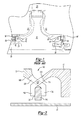
Figure 1 is a cutaway view of a turbine rotor incorporating a prior art cover plate. -
Figure 2 is a functional, schematic cutaway view of a cover plate retention device. -
Figure 3 is a schematic view of the cover plate retention device ofFigure 2 . -
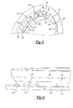
Figure 4 is a perspective view of a portion of a cover plate extending through a portion of a rotor disk. -
Figure 5 is a perspective view of a portion of a rotor plate extending through a portion of a cover plate. -
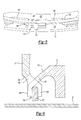
Figure 6 is an alternative embodiment of the cover plate ofFigure 4 . - Referring now to
Figure 1 , a priorart rotor disk 10, a pair ofcover plates 15, and aturbine blade 20 are shown. Therotor disk 10 attaches to ashaft 25 by known means. Eachrotor disk 10 has a pair of axially extendinghubs 30. Eachhub 30 has a radially extendingflange 35 that hasholes 40 therein for receivingbolts 45. Eachcover plate 15 has a radially inwardly extendingflange 50 having anholes 53 for mating with the radially extendinghub 35 of therotor disk 10 so that thebolts 45 may be extended through the radially extendingflanges cover plate 15, as is known in the art, is contoured closely to the shape of therotor disk 10 so that air cooling may be distributed along therotor disk 10 to theturbine blade 20. As therotor disk 10 rotates so do thecover plates 15. Because of the axially extendingflanges 30 and the axial length of thebolts 45 required, this configuration takes up significant axial room and involves multiple pieces. - Referring now to
Figures 2-5 , in an exemplar of a coverplate interlock mechanism 100 is shown. Theinterlock mechanism 100 includes acover plate flange 105, arotor disk flange 110 and aring 140 which acts as a holder to hold or lock thecover plate 15 and therotor plate 10 together. Thecover plate flange 105 has a plurality ofcover plate slots 115 and therotor disk flange 110 has a plurality ofrotor disk slots 120 as will be discussed herein for receiving the other of thecover plate flange 105 or therotor disk flange 110. Theretention ring 140 anchors thecover plate flange 105 and therotor disk flange 110 within each of the other of thecover plate flange 105 and therotor disk flange 110 as will be discussed herein. The rotor plate and thecover plate slots cover plate flange 105 and therotor disk flange 110 on each of therotor disk 10 and thecover plate 15 so that thecover plate flange 105 or therotor disk flange 110 of each of therotor disk 10 and thecover plate 15 essentially interleave like fingers. - As shown in
Figures 2 -5 , thecover plate flange 105 is angled radially and axially toward therotor disk flange 110. Similarly therotor disk flange 110 is angled radially and axially toward thecover plate flange 105. Thecover plate flange 105 has a plurality ofradial finger portions 130 and therotor disk flange 110 has a plurality ofradial finger portions 145, each radial finger portion extending through a slot in the other flange and perpendicular to theshaft 25 which forms a center line like intermeshed fingers. Theradial finger portions flange channel 135 for receiving theretention ring 140. - The
interlock mechanism 100 axially, radially, and angularly attaches cylindrical-like components, such as cover plates and disks as shown. Though acover plate 15 is shown attaching to arotor disk 10, the coupling of parts that may have other shapes by theinterlock mechanism 100 is contemplated herein. - To assemble the interlock mechanism, the
portions 125 of eachflange cover plate 15 and therotor disk 10 are interleaved through theslots 115. 120 formed betweenportions 125 of the other part. After interleaving is complete, thering 140 is inserted in thechannel 135 formed by theradial finger portions 130. Thering 140 may be split for ease of insertion. - Referring now to
Figure 6 , a further example is shown. Thecover plate flange 105 has a secondradial finger portion 155 extending radially inwardly towards theshaft 25 such that the secondradial finger portion 155 and theradial finger portion 130 form afork 160 that holds theretention ring 140 therein. Though thecover plate flange 105 is shown having finger portions that form a fork, therotor disk flange 110 may also have two finger portions forming a fork. - Although a combination of features is shown in the illustrated examples, not all of them need to be combined to realize the benefits of various embodiments of this disclosure. In other words, a system designed according to an embodiment of this disclosure will not necessarily include all of the features shown in any one of the Figures or all of the portions schematically shown in the Figures. Moreover, selected features of one example embodiment may be combined with selected features of other example embodiments.
- The preceding description is exemplary rather than limiting in nature. Variations and modifications to the disclosed examples may become apparent to those skilled in the art that do not necessarily depart from the essence of this disclosure. The scope of legal protection given to this disclosure can only be determined by studying the following claims.
Claims (10)
- A joining mechanism (100) comprising;
a first body (15),
a second body (10),
a first slot (115) in the first body (15),
a second slot (120) in the second body (10),
a first finger (130) in the first body (15) extending through the second slot (120)
a second finger (145) in the second body (120) extending through the first slot (115) wherein the first finger (130) and the second finger (145) form a first channel (135), and
a holder (140) disposed in the channel (135) for locking the first body (15) and the second body (10) together. - The mechanism of claim 1 wherein the holder (140) is a ring.
- The mechanism of claim 1 or 2 wherein either of the first finger (130) or the second finger (145) forms a fork (160) having a first side and a second side.
- The mechanism of claim 3 wherein one of the first side or the second side of the fork (160) extends through the first slot (115) and/or the second slot (120).
- The mechanism of claim 3 or 4 wherein the first side and the second side of the fork (160) form a second channel.
- The mechanism of any preceding claim wherein either of the first finger (130) or the second finger (145) has a radially and axially extending angled portion extending through an other of the first slot (115) and/or the second slot (120).
- The mechanism of any preceding claim wherein either of the first finger (130) or the second finger (145) has a radial inward portion.
- The mechanism of claim 7 wherein a plurality of said radial inward portion forms said first channel (135).
- The mechanism of any preceding claim for use in a gas turbine engine, wherein the first body (15) is a cover plate and the second body is a rotor disk.
- The mechanism of any of claims 1 to 9 for use in rotating equipment, wherein the first body (15) is a first rotating body and the second body (20) is a second rotating body.
Applications Claiming Priority (1)
| Application Number | Priority Date | Filing Date | Title |
|---|---|---|---|
| US12/846,304 US8870544B2 (en) | 2010-07-29 | 2010-07-29 | Rotor cover plate retention method |
Publications (3)
| Publication Number | Publication Date |
|---|---|
| EP2412923A2 true EP2412923A2 (en) | 2012-02-01 |
| EP2412923A3 EP2412923A3 (en) | 2015-04-08 |
| EP2412923B1 EP2412923B1 (en) | 2018-12-19 |
Family
ID=44352272
Family Applications (1)
| Application Number | Title | Priority Date | Filing Date |
|---|---|---|---|
| EP11173345.7A Active EP2412923B1 (en) | 2010-07-29 | 2011-07-08 | Rotor cover plate retention |
Country Status (2)
| Country | Link |
|---|---|
| US (1) | US8870544B2 (en) |
| EP (1) | EP2412923B1 (en) |
Cited By (4)
| Publication number | Priority date | Publication date | Assignee | Title |
|---|---|---|---|---|
| WO2014172130A1 (en) | 2013-04-18 | 2014-10-23 | United Technologies Corporation | Turbine minidisk bumper for gas turbine engine |
| WO2021023470A1 (en) * | 2019-08-06 | 2021-02-11 | Safran Aircraft Engines | Aircraft turboshaft engine compressor comprising a device for immobilising a retaining ring |
| EP3617452B1 (en) | 2018-08-29 | 2021-05-19 | Safran Aircraft Engines | Coupling for turbomachine, corresponding turbine and turbomachine |
| EP2984303B1 (en) * | 2013-04-12 | 2024-12-04 | RTX Corporation | Cover plate for a rotor assembly of a gas turbine engine |
Families Citing this family (12)
| Publication number | Priority date | Publication date | Assignee | Title |
|---|---|---|---|---|
| DE102010015404B4 (en) * | 2010-04-19 | 2012-02-16 | Mtu Aero Engines Gmbh | Method for repairing a rotor assembly of a turbomachine, ring element for a rotor assembly of a turbomachine and rotor assembly for a turbomachine |
| US8840375B2 (en) * | 2011-03-21 | 2014-09-23 | United Technologies Corporation | Component lock for a gas turbine engine |
| US9249676B2 (en) | 2012-06-05 | 2016-02-02 | United Technologies Corporation | Turbine rotor cover plate lock |
| US9212562B2 (en) * | 2012-07-18 | 2015-12-15 | United Technologies Corporation | Bayoneted anti-rotation turbine seals |
| FR2995340B1 (en) * | 2012-09-12 | 2026-03-06 | Snecma | THERMAL PROTECTION SHEET WITH RADIAL BARRIER, PARTICULARLY FOR TURBOMACHINE DISTRIBUTOR |
| US9567857B2 (en) | 2013-03-08 | 2017-02-14 | Rolls-Royce North American Technologies, Inc. | Turbine split ring retention and anti-rotation method |
| US10662793B2 (en) | 2014-12-01 | 2020-05-26 | General Electric Company | Turbine wheel cover-plate mounted gas turbine interstage seal |
| US9771814B2 (en) | 2015-03-09 | 2017-09-26 | United Technologies Corporation | Tolerance resistance coverplates |
| US10329929B2 (en) * | 2016-03-15 | 2019-06-25 | United Technologies Corporation | Retaining ring axially loaded against segmented disc surface |
| US10323519B2 (en) * | 2016-06-23 | 2019-06-18 | United Technologies Corporation | Gas turbine engine having a turbine rotor with torque transfer and balance features |
| US10669877B2 (en) * | 2017-12-21 | 2020-06-02 | United Technologies Corporation | Air seal attachment |
| US11168565B2 (en) * | 2018-08-28 | 2021-11-09 | Raytheon Technologies Corporation | Heat shield insert |
Family Cites Families (13)
| Publication number | Priority date | Publication date | Assignee | Title |
|---|---|---|---|---|
| DE1025422B (en) * | 1957-02-16 | 1958-03-06 | Maschf Augsburg Nuernberg Ag | Composite runner for axially flowed turbines or compressors |
| DE1400287A1 (en) * | 1961-11-14 | 1968-10-24 | Elektro Und Feinmechanik Aache | Divided machine element made of pressed sintered materials |
| BE792286A (en) | 1971-12-06 | 1973-03-30 | Gen Electric | BOLTLESS AUBA RETAINER FOR TURBOMACHIN ROTOR |
| US4349318A (en) | 1980-01-04 | 1982-09-14 | Avco Corporation | Boltless blade retainer for a turbine wheel |
| US4304523A (en) | 1980-06-23 | 1981-12-08 | General Electric Company | Means and method for securing a member to a structure |
| US4558988A (en) | 1983-12-22 | 1985-12-17 | United Technologies Corporation | Rotor disk cover plate attachment |
| US4701105A (en) | 1986-03-10 | 1987-10-20 | United Technologies Corporation | Anti-rotation feature for a turbine rotor faceplate |
| US5257909A (en) * | 1992-08-17 | 1993-11-02 | General Electric Company | Dovetail sealing device for axial dovetail rotor blades |
| FR2695433B1 (en) * | 1992-09-09 | 1994-10-21 | Snecma | Annular seal placed at an axial end of a rotor and covering blade pinouts. |
| US5338154A (en) * | 1993-03-17 | 1994-08-16 | General Electric Company | Turbine disk interstage seal axial retaining ring |
| US6575703B2 (en) * | 2001-07-20 | 2003-06-10 | General Electric Company | Turbine disk side plate |
| FR2850130B1 (en) * | 2003-01-16 | 2006-01-20 | Snecma Moteurs | DEVICE FOR RETAINING AN ANNULAR FLASK AGAINST A RADIAL FACE OF A DISK |
| US8313289B2 (en) | 2007-12-07 | 2012-11-20 | United Technologies Corp. | Gas turbine engine systems involving rotor bayonet coverplates and tools for installing such coverplates |
-
2010
- 2010-07-29 US US12/846,304 patent/US8870544B2/en active Active
-
2011
- 2011-07-08 EP EP11173345.7A patent/EP2412923B1/en active Active
Non-Patent Citations (1)
| Title |
|---|
| None |
Cited By (9)
| Publication number | Priority date | Publication date | Assignee | Title |
|---|---|---|---|---|
| EP2984303B1 (en) * | 2013-04-12 | 2024-12-04 | RTX Corporation | Cover plate for a rotor assembly of a gas turbine engine |
| WO2014172130A1 (en) | 2013-04-18 | 2014-10-23 | United Technologies Corporation | Turbine minidisk bumper for gas turbine engine |
| EP2986824A4 (en) * | 2013-04-18 | 2016-12-21 | United Technologies Corp | TURBINE MINIDIC SHOCK ABSORBER FOR GAS TURBINE |
| US10221761B2 (en) | 2013-04-18 | 2019-03-05 | United Technologies Corporation | Turbine minidisk bumper for gas turbine engine |
| US10989111B2 (en) | 2013-04-18 | 2021-04-27 | Raytheon Technologies Corporation | Turbine minidisk bumper for gas turbine engine |
| EP3617452B1 (en) | 2018-08-29 | 2021-05-19 | Safran Aircraft Engines | Coupling for turbomachine, corresponding turbine and turbomachine |
| WO2021023470A1 (en) * | 2019-08-06 | 2021-02-11 | Safran Aircraft Engines | Aircraft turboshaft engine compressor comprising a device for immobilising a retaining ring |
| FR3099792A1 (en) * | 2019-08-06 | 2021-02-12 | Safran Aircraft Engines | Aircraft turbine engine compressor comprising a device for locking a retaining ring |
| US11859508B2 (en) | 2019-08-06 | 2024-01-02 | Safran Aircraft Engines | Aircraft turboshaft engine compressor comprising a device for immobilising a retaining annulus |
Also Published As
| Publication number | Publication date |
|---|---|
| US20120027598A1 (en) | 2012-02-02 |
| EP2412923A3 (en) | 2015-04-08 |
| EP2412923B1 (en) | 2018-12-19 |
| US8870544B2 (en) | 2014-10-28 |
Similar Documents
| Publication | Publication Date | Title |
|---|---|---|
| US8870544B2 (en) | Rotor cover plate retention method | |
| EP3640432B1 (en) | Turbine shroud assemblies for gas turbine engines | |
| EP2075411B1 (en) | Integrally bladed rotor with slotted outer rim and gas turbine engine comprising such a rotor | |
| US10221715B2 (en) | Turbine shroud with axially separated pressure compartments | |
| EP2613000B1 (en) | System for axial retention of rotating segments of a turbine and corresponding method | |
| EP1788195A2 (en) | Blades for gas turbine engines | |
| US9109450B2 (en) | Rotor assembly with interlocking tabs | |
| US7258529B2 (en) | Securing assembly | |
| US10385707B2 (en) | Turbine disc interstage coupling with retention ring features | |
| CN102220885A (en) | Locking spacer assembly for circumferential attachment | |
| US10352175B2 (en) | Seal-plate anti-rotation in a stage of a gas turbine engine | |
| EP3273013B1 (en) | Assembly for a turbine engine | |
| EP3159503B1 (en) | Compressor bleeding arrangement for a gas turbine and method of manufacturing a compressor section for a gas turbine | |
| US10539029B2 (en) | Dual snapped cover plate with retention ring attachment | |
| US9422819B2 (en) | Rotor blade root spacer for arranging between a rotor disk and a root of a rotor blade | |
| EP3219909B1 (en) | Disc for a gas turbine engine, rotor assembly, and gas turbine | |
| US11021974B2 (en) | Turbine wheel assembly with retainer rings for ceramic matrix composite material blades | |
| US10577961B2 (en) | Turbine disk with blade supported platforms | |
| EP3130751B1 (en) | Apparatus and method for cooling the rotor of a gas turbine | |
| US7056094B2 (en) | Rotor and a retaining plate for the same | |
| US10400615B2 (en) | Retaining ring groove submerged into disc bore or hub | |
| JP2026003576A (en) | Turbine airfoil and gas turbine including the airfoil |
Legal Events
| Date | Code | Title | Description |
|---|---|---|---|
| AK | Designated contracting states |
Kind code of ref document: A2 Designated state(s): AL AT BE BG CH CY CZ DE DK EE ES FI FR GB GR HR HU IE IS IT LI LT LU LV MC MK MT NL NO PL PT RO RS SE SI SK SM TR |
|
| AX | Request for extension of the european patent |
Extension state: BA ME |
|
| PUAI | Public reference made under article 153(3) epc to a published international application that has entered the european phase |
Free format text: ORIGINAL CODE: 0009012 |
|
| PUAL | Search report despatched |
Free format text: ORIGINAL CODE: 0009013 |
|
| AK | Designated contracting states |
Kind code of ref document: A3 Designated state(s): AL AT BE BG CH CY CZ DE DK EE ES FI FR GB GR HR HU IE IS IT LI LT LU LV MC MK MT NL NO PL PT RO RS SE SI SK SM TR |
|
| AX | Request for extension of the european patent |
Extension state: BA ME |
|
| RIC1 | Information provided on ipc code assigned before grant |
Ipc: F01D 5/06 20060101ALI20150304BHEP Ipc: F01D 5/08 20060101AFI20150304BHEP |
|
| 17P | Request for examination filed |
Effective date: 20151008 |
|
| RBV | Designated contracting states (corrected) |
Designated state(s): AL AT BE BG CH CY CZ DE DK EE ES FI FR GB GR HR HU IE IS IT LI LT LU LV MC MK MT NL NO PL PT RO RS SE SI SK SM TR |
|
| RAP1 | Party data changed (applicant data changed or rights of an application transferred) |
Owner name: UNITED TECHNOLOGIES CORPORATION |
|
| GRAP | Despatch of communication of intention to grant a patent |
Free format text: ORIGINAL CODE: EPIDOSNIGR1 |
|
| STAA | Information on the status of an ep patent application or granted ep patent |
Free format text: STATUS: GRANT OF PATENT IS INTENDED |
|
| INTG | Intention to grant announced |
Effective date: 20180628 |
|
| GRAS | Grant fee paid |
Free format text: ORIGINAL CODE: EPIDOSNIGR3 |
|
| GRAA | (expected) grant |
Free format text: ORIGINAL CODE: 0009210 |
|
| STAA | Information on the status of an ep patent application or granted ep patent |
Free format text: STATUS: THE PATENT HAS BEEN GRANTED |
|
| AK | Designated contracting states |
Kind code of ref document: B1 Designated state(s): AL AT BE BG CH CY CZ DE DK EE ES FI FR GB GR HR HU IE IS IT LI LT LU LV MC MK MT NL NO PL PT RO RS SE SI SK SM TR |
|
| REG | Reference to a national code |
Ref country code: GB Ref legal event code: FG4D |
|
| REG | Reference to a national code |
Ref country code: CH Ref legal event code: EP |
|
| REG | Reference to a national code |
Ref country code: IE Ref legal event code: FG4D |
|
| REG | Reference to a national code |
Ref country code: DE Ref legal event code: R096 Ref document number: 602011054910 Country of ref document: DE |
|
| REG | Reference to a national code |
Ref country code: AT Ref legal event code: REF Ref document number: 1078933 Country of ref document: AT Kind code of ref document: T Effective date: 20190115 |
|
| REG | Reference to a national code |
Ref country code: NL Ref legal event code: MP Effective date: 20181219 |
|
| PG25 | Lapsed in a contracting state [announced via postgrant information from national office to epo] |
Ref country code: BG Free format text: LAPSE BECAUSE OF FAILURE TO SUBMIT A TRANSLATION OF THE DESCRIPTION OR TO PAY THE FEE WITHIN THE PRESCRIBED TIME-LIMIT Effective date: 20190319 Ref country code: LT Free format text: LAPSE BECAUSE OF FAILURE TO SUBMIT A TRANSLATION OF THE DESCRIPTION OR TO PAY THE FEE WITHIN THE PRESCRIBED TIME-LIMIT Effective date: 20181219 Ref country code: NO Free format text: LAPSE BECAUSE OF FAILURE TO SUBMIT A TRANSLATION OF THE DESCRIPTION OR TO PAY THE FEE WITHIN THE PRESCRIBED TIME-LIMIT Effective date: 20190319 Ref country code: HR Free format text: LAPSE BECAUSE OF FAILURE TO SUBMIT A TRANSLATION OF THE DESCRIPTION OR TO PAY THE FEE WITHIN THE PRESCRIBED TIME-LIMIT Effective date: 20181219 Ref country code: LV Free format text: LAPSE BECAUSE OF FAILURE TO SUBMIT A TRANSLATION OF THE DESCRIPTION OR TO PAY THE FEE WITHIN THE PRESCRIBED TIME-LIMIT Effective date: 20181219 Ref country code: FI Free format text: LAPSE BECAUSE OF FAILURE TO SUBMIT A TRANSLATION OF THE DESCRIPTION OR TO PAY THE FEE WITHIN THE PRESCRIBED TIME-LIMIT Effective date: 20181219 |
|
| REG | Reference to a national code |
Ref country code: LT Ref legal event code: MG4D |
|
| REG | Reference to a national code |
Ref country code: AT Ref legal event code: MK05 Ref document number: 1078933 Country of ref document: AT Kind code of ref document: T Effective date: 20181219 |
|
| PG25 | Lapsed in a contracting state [announced via postgrant information from national office to epo] |
Ref country code: AL Free format text: LAPSE BECAUSE OF FAILURE TO SUBMIT A TRANSLATION OF THE DESCRIPTION OR TO PAY THE FEE WITHIN THE PRESCRIBED TIME-LIMIT Effective date: 20181219 Ref country code: GR Free format text: LAPSE BECAUSE OF FAILURE TO SUBMIT A TRANSLATION OF THE DESCRIPTION OR TO PAY THE FEE WITHIN THE PRESCRIBED TIME-LIMIT Effective date: 20190320 Ref country code: SE Free format text: LAPSE BECAUSE OF FAILURE TO SUBMIT A TRANSLATION OF THE DESCRIPTION OR TO PAY THE FEE WITHIN THE PRESCRIBED TIME-LIMIT Effective date: 20181219 Ref country code: RS Free format text: LAPSE BECAUSE OF FAILURE TO SUBMIT A TRANSLATION OF THE DESCRIPTION OR TO PAY THE FEE WITHIN THE PRESCRIBED TIME-LIMIT Effective date: 20181219 |
|
| PG25 | Lapsed in a contracting state [announced via postgrant information from national office to epo] |
Ref country code: NL Free format text: LAPSE BECAUSE OF FAILURE TO SUBMIT A TRANSLATION OF THE DESCRIPTION OR TO PAY THE FEE WITHIN THE PRESCRIBED TIME-LIMIT Effective date: 20181219 |
|
| PG25 | Lapsed in a contracting state [announced via postgrant information from national office to epo] |
Ref country code: CZ Free format text: LAPSE BECAUSE OF FAILURE TO SUBMIT A TRANSLATION OF THE DESCRIPTION OR TO PAY THE FEE WITHIN THE PRESCRIBED TIME-LIMIT Effective date: 20181219 Ref country code: IT Free format text: LAPSE BECAUSE OF FAILURE TO SUBMIT A TRANSLATION OF THE DESCRIPTION OR TO PAY THE FEE WITHIN THE PRESCRIBED TIME-LIMIT Effective date: 20181219 Ref country code: PT Free format text: LAPSE BECAUSE OF FAILURE TO SUBMIT A TRANSLATION OF THE DESCRIPTION OR TO PAY THE FEE WITHIN THE PRESCRIBED TIME-LIMIT Effective date: 20190419 Ref country code: PL Free format text: LAPSE BECAUSE OF FAILURE TO SUBMIT A TRANSLATION OF THE DESCRIPTION OR TO PAY THE FEE WITHIN THE PRESCRIBED TIME-LIMIT Effective date: 20181219 Ref country code: ES Free format text: LAPSE BECAUSE OF FAILURE TO SUBMIT A TRANSLATION OF THE DESCRIPTION OR TO PAY THE FEE WITHIN THE PRESCRIBED TIME-LIMIT Effective date: 20181219 |
|
| PG25 | Lapsed in a contracting state [announced via postgrant information from national office to epo] |
Ref country code: SM Free format text: LAPSE BECAUSE OF FAILURE TO SUBMIT A TRANSLATION OF THE DESCRIPTION OR TO PAY THE FEE WITHIN THE PRESCRIBED TIME-LIMIT Effective date: 20181219 Ref country code: EE Free format text: LAPSE BECAUSE OF FAILURE TO SUBMIT A TRANSLATION OF THE DESCRIPTION OR TO PAY THE FEE WITHIN THE PRESCRIBED TIME-LIMIT Effective date: 20181219 Ref country code: IS Free format text: LAPSE BECAUSE OF FAILURE TO SUBMIT A TRANSLATION OF THE DESCRIPTION OR TO PAY THE FEE WITHIN THE PRESCRIBED TIME-LIMIT Effective date: 20190419 Ref country code: RO Free format text: LAPSE BECAUSE OF FAILURE TO SUBMIT A TRANSLATION OF THE DESCRIPTION OR TO PAY THE FEE WITHIN THE PRESCRIBED TIME-LIMIT Effective date: 20181219 Ref country code: SK Free format text: LAPSE BECAUSE OF FAILURE TO SUBMIT A TRANSLATION OF THE DESCRIPTION OR TO PAY THE FEE WITHIN THE PRESCRIBED TIME-LIMIT Effective date: 20181219 |
|
| REG | Reference to a national code |
Ref country code: DE Ref legal event code: R097 Ref document number: 602011054910 Country of ref document: DE |
|
| PLBE | No opposition filed within time limit |
Free format text: ORIGINAL CODE: 0009261 |
|
| STAA | Information on the status of an ep patent application or granted ep patent |
Free format text: STATUS: NO OPPOSITION FILED WITHIN TIME LIMIT |
|
| PG25 | Lapsed in a contracting state [announced via postgrant information from national office to epo] |
Ref country code: DK Free format text: LAPSE BECAUSE OF FAILURE TO SUBMIT A TRANSLATION OF THE DESCRIPTION OR TO PAY THE FEE WITHIN THE PRESCRIBED TIME-LIMIT Effective date: 20181219 Ref country code: AT Free format text: LAPSE BECAUSE OF FAILURE TO SUBMIT A TRANSLATION OF THE DESCRIPTION OR TO PAY THE FEE WITHIN THE PRESCRIBED TIME-LIMIT Effective date: 20181219 |
|
| 26N | No opposition filed |
Effective date: 20190920 |
|
| PG25 | Lapsed in a contracting state [announced via postgrant information from national office to epo] |
Ref country code: SI Free format text: LAPSE BECAUSE OF FAILURE TO SUBMIT A TRANSLATION OF THE DESCRIPTION OR TO PAY THE FEE WITHIN THE PRESCRIBED TIME-LIMIT Effective date: 20181219 Ref country code: MC Free format text: LAPSE BECAUSE OF FAILURE TO SUBMIT A TRANSLATION OF THE DESCRIPTION OR TO PAY THE FEE WITHIN THE PRESCRIBED TIME-LIMIT Effective date: 20181219 |
|
| REG | Reference to a national code |
Ref country code: CH Ref legal event code: PL |
|
| PG25 | Lapsed in a contracting state [announced via postgrant information from national office to epo] |
Ref country code: TR Free format text: LAPSE BECAUSE OF FAILURE TO SUBMIT A TRANSLATION OF THE DESCRIPTION OR TO PAY THE FEE WITHIN THE PRESCRIBED TIME-LIMIT Effective date: 20181219 |
|
| REG | Reference to a national code |
Ref country code: BE Ref legal event code: MM Effective date: 20190731 |
|
| PG25 | Lapsed in a contracting state [announced via postgrant information from national office to epo] |
Ref country code: BE Free format text: LAPSE BECAUSE OF NON-PAYMENT OF DUE FEES Effective date: 20190731 Ref country code: LI Free format text: LAPSE BECAUSE OF NON-PAYMENT OF DUE FEES Effective date: 20190731 Ref country code: CH Free format text: LAPSE BECAUSE OF NON-PAYMENT OF DUE FEES Effective date: 20190731 Ref country code: LU Free format text: LAPSE BECAUSE OF NON-PAYMENT OF DUE FEES Effective date: 20190708 |
|
| PG25 | Lapsed in a contracting state [announced via postgrant information from national office to epo] |
Ref country code: IE Free format text: LAPSE BECAUSE OF NON-PAYMENT OF DUE FEES Effective date: 20190708 |
|
| PG25 | Lapsed in a contracting state [announced via postgrant information from national office to epo] |
Ref country code: CY Free format text: LAPSE BECAUSE OF FAILURE TO SUBMIT A TRANSLATION OF THE DESCRIPTION OR TO PAY THE FEE WITHIN THE PRESCRIBED TIME-LIMIT Effective date: 20181219 |
|
| PG25 | Lapsed in a contracting state [announced via postgrant information from national office to epo] |
Ref country code: MT Free format text: LAPSE BECAUSE OF FAILURE TO SUBMIT A TRANSLATION OF THE DESCRIPTION OR TO PAY THE FEE WITHIN THE PRESCRIBED TIME-LIMIT Effective date: 20181219 Ref country code: HU Free format text: LAPSE BECAUSE OF FAILURE TO SUBMIT A TRANSLATION OF THE DESCRIPTION OR TO PAY THE FEE WITHIN THE PRESCRIBED TIME-LIMIT; INVALID AB INITIO Effective date: 20110708 |
|
| PG25 | Lapsed in a contracting state [announced via postgrant information from national office to epo] |
Ref country code: MK Free format text: LAPSE BECAUSE OF FAILURE TO SUBMIT A TRANSLATION OF THE DESCRIPTION OR TO PAY THE FEE WITHIN THE PRESCRIBED TIME-LIMIT Effective date: 20181219 |
|
| REG | Reference to a national code |
Ref country code: DE Ref legal event code: R081 Ref document number: 602011054910 Country of ref document: DE Owner name: RAYTHEON TECHNOLOGIES CORPORATION (N.D.GES.D.S, US Free format text: FORMER OWNER: UNITED TECHNOLOGIES CORPORATION, FARMINGTON, CONN., US Ref country code: DE Ref legal event code: R081 Ref document number: 602011054910 Country of ref document: DE Owner name: RTX CORPORATION (N.D.GES.D. STAATES DELAWARE),, US Free format text: FORMER OWNER: UNITED TECHNOLOGIES CORPORATION, FARMINGTON, CONN., US |
|
| P01 | Opt-out of the competence of the unified patent court (upc) registered |
Effective date: 20230519 |
|
| PGFP | Annual fee paid to national office [announced via postgrant information from national office to epo] |
Ref country code: GB Payment date: 20250619 Year of fee payment: 15 |
|
| PGFP | Annual fee paid to national office [announced via postgrant information from national office to epo] |
Ref country code: FR Payment date: 20250620 Year of fee payment: 15 |
|
| PGFP | Annual fee paid to national office [announced via postgrant information from national office to epo] |
Ref country code: DE Payment date: 20250620 Year of fee payment: 15 |
|
| REG | Reference to a national code |
Ref country code: DE Ref legal event code: R081 Ref document number: 602011054910 Country of ref document: DE Owner name: RTX CORPORATION (N.D.GES.D. STAATES DELAWARE),, US Free format text: FORMER OWNER: RAYTHEON TECHNOLOGIES CORPORATION (N.D.GES.D.STAATES DELAWARE), ARLINGTON, VA, US |