EP2412653A1 - Valve for powder - Google Patents
Valve for powder Download PDFInfo
- Publication number
- EP2412653A1 EP2412653A1 EP09842237A EP09842237A EP2412653A1 EP 2412653 A1 EP2412653 A1 EP 2412653A1 EP 09842237 A EP09842237 A EP 09842237A EP 09842237 A EP09842237 A EP 09842237A EP 2412653 A1 EP2412653 A1 EP 2412653A1
- Authority
- EP
- European Patent Office
- Prior art keywords
- valve
- powder
- valve body
- communication hole
- casing
- Prior art date
- Legal status (The legal status is an assumption and is not a legal conclusion. Google has not performed a legal analysis and makes no representation as to the accuracy of the status listed.)
- Withdrawn
Links
- 239000000843 powder Substances 0.000 title claims abstract description 63
- 239000007789 gas Substances 0.000 description 6
- 238000002347 injection Methods 0.000 description 5
- 239000007924 injection Substances 0.000 description 5
- 238000012423 maintenance Methods 0.000 description 1
- NMJORVOYSJLJGU-UHFFFAOYSA-N methane clathrate Chemical compound C.C.C.C.O.O.O.O.O.O.O.O.O.O.O.O.O.O.O.O.O.O.O.O.O.O.O NMJORVOYSJLJGU-UHFFFAOYSA-N 0.000 description 1
- 239000002574 poison Substances 0.000 description 1
- 231100000614 poison Toxicity 0.000 description 1
- 239000008399 tap water Substances 0.000 description 1
- 235000020679 tap water Nutrition 0.000 description 1
Images


Classifications
-
- F—MECHANICAL ENGINEERING; LIGHTING; HEATING; WEAPONS; BLASTING
- F16—ENGINEERING ELEMENTS AND UNITS; GENERAL MEASURES FOR PRODUCING AND MAINTAINING EFFECTIVE FUNCTIONING OF MACHINES OR INSTALLATIONS; THERMAL INSULATION IN GENERAL
- F16K—VALVES; TAPS; COCKS; ACTUATING-FLOATS; DEVICES FOR VENTING OR AERATING
- F16K5/00—Plug valves; Taps or cocks comprising only cut-off apparatus having at least one of the sealing faces shaped as a more or less complete surface of a solid of revolution, the opening and closing movement being predominantly rotary
- F16K5/06—Plug valves; Taps or cocks comprising only cut-off apparatus having at least one of the sealing faces shaped as a more or less complete surface of a solid of revolution, the opening and closing movement being predominantly rotary with plugs having spherical surfaces; Packings therefor
- F16K5/0605—Plug valves; Taps or cocks comprising only cut-off apparatus having at least one of the sealing faces shaped as a more or less complete surface of a solid of revolution, the opening and closing movement being predominantly rotary with plugs having spherical surfaces; Packings therefor with particular plug arrangements, e.g. particular shape or built-in means
-
- B—PERFORMING OPERATIONS; TRANSPORTING
- B65—CONVEYING; PACKING; STORING; HANDLING THIN OR FILAMENTARY MATERIAL
- B65G—TRANSPORT OR STORAGE DEVICES, e.g. CONVEYORS FOR LOADING OR TIPPING, SHOP CONVEYOR SYSTEMS OR PNEUMATIC TUBE CONVEYORS
- B65G53/00—Conveying materials in bulk through troughs, pipes or tubes by floating the materials or by flow of gas, liquid or foam
- B65G53/34—Details
- B65G53/40—Feeding or discharging devices
- B65G53/46—Gates or sluices, e.g. rotary wheels
- B65G53/4608—Turnable elements, e.g. rotary wheels with pockets or passages for material
- B65G53/4625—Turnable elements, e.g. rotary wheels with pockets or passages for material with axis of turning perpendicular to flow
- B65G53/4658—Turnable elements, e.g. rotary wheels with pockets or passages for material with axis of turning perpendicular to flow the element having passages simultaneously connectable to both inlet and outlet ports
-
- B—PERFORMING OPERATIONS; TRANSPORTING
- B65—CONVEYING; PACKING; STORING; HANDLING THIN OR FILAMENTARY MATERIAL
- B65G—TRANSPORT OR STORAGE DEVICES, e.g. CONVEYORS FOR LOADING OR TIPPING, SHOP CONVEYOR SYSTEMS OR PNEUMATIC TUBE CONVEYORS
- B65G65/00—Loading or unloading
- B65G65/30—Methods or devices for filling or emptying bunkers, hoppers, tanks, or like containers, of interest apart from their use in particular chemical or physical processes or their application in particular machines, e.g. not covered by a single other subclass
- B65G65/34—Emptying devices
- B65G65/40—Devices for emptying otherwise than from the top
- B65G65/48—Devices for emptying otherwise than from the top using other rotating means, e.g. rotating pressure sluices in pneumatic systems
- B65G65/4881—Devices for emptying otherwise than from the top using other rotating means, e.g. rotating pressure sluices in pneumatic systems rotating about a substantially horizontal axis
Definitions
- the present invention relates to a powder valve used to open and close a passage through which powder is transferred.
- a valve On-off valve
- This valve is used to control the feed amount of powder, and especially if powder is fed under high pressure, this valve is frequently a full-bore valve or a ball valve, of which the valve body has high rigidity.
- a ball valve such as a powder valve 10 shown in Fig. 7
- powder introduced through an inlet port 11 of a valve housing 1 mostly flows through a communication hole 6 formed in the valve body 2 into an outlet port 12 (see arrows A and B in Fig. 7 ).
- part of the powder tends to get stuck in the gap 4 between the valve casing 1 and the valve body 2.
- This phenomenon tends to occur when the valve body 2 is slightly open (i.e. when the valve body 2 is in a position between the fully open position and the fully closed position where the valve hole is slightly open). If such powder is left unattended, it may interfere with smooth opening and closing of the valve.
- the powder is coagulable, power that has entered the gap tends to coagulate and the coagulated masses could grow to such an extent as to make it impossible to open and close the valve.
- Fig. 8 shows a conventional segment ball valve for use in a tap water system.
- this segment ball valve (such as the one disclosed in Patent document 2) can be opened by turning the valve body 2 either clockwise or counterclockwise from the closed position shown.
- the valve body 2 of this valve is lightweight.
- the valve shown in Fig. 8 has a valve body comprising a plate member having a front side configured to be brought into and out of contact with the valve seat, and a support member protruding from the back side of the plate member and supported by the valve shaft.
- the valve body is not spherical as in the case with the valve body of a ball valve.
- the valve body of this valve is therefore low in rigidity compared to the valve body of an ordinary ball valve. Since the valve body is low in rigidity, especially if powder is fed under high pressure, the valve body may not be able to withstand the feed pressure. If a valve body is used which can withstand high feed pressure, it will be necessary to use a large and expensive valve device.
- An object of the present invention is to provide a powder valve which is simple in structure and small in size, which can prevent powder from getting stuck in the valve, and can withstand high feed pressure.
- the present invention provides a valve for powder comprising a valve casing, a valve shaft, a valve body mounted in the valve casing and rotatably supported by the valve shaft, the valve casing having an inlet port, and an annular valve seat provided at the inlet port of the valve casing, wherein the valve body has a spherical outer surface configured to be brought into contact with the valve seat over the entire circumference of the valve seat when the valve body is in a closed position, wherein the valve body is formed with a communication hole extending in a direction perpendicular to an axis p of the valve shaft, wherein when the valve body is rotated about the valve shaft in either of two opposite directions from the closed position, the valve is configured to open through the communication hole, and wherein the communication hole is open at its portion opposite to its side facing the valve seat in the closed position, over an entire length of the communication hole.
- the flow of powder blows off and removes any powder which could otherwise get stuck on this portion of the inner periphery of the valve casing. Since the valve can be opened by rotating the valve body about the valve shaft in either direction from the closed position, it is possible to remove powder that have gotten stuck on the inner periphery of the valve casing on both sides of the valve shaft by rotating the valve body in both directions.
- a powder valve which is simple in structure and small in size, which can prevent powder from getting stuck in the valve, and can withstand high feed pressure.
- the valve body may be hemispherical.
- a hemispherical valve body significantly increases the distance between the valve body and the valve casing on the open side of the communication hole (which is the opposite side of the spherical surface) in the open position. Since this distance is large, the pressure of powder flowing through the communication hole can more readily act on the entire inner periphery of the valve casing, which in turn makes it possible to more effectively remove powder stuck on the inner periphery of the valve casing.
- Another advantage of the hemispherical valve body is that it is lighter in weight than a completely spherical valve body while keeping its sufficient rigidity.
- the inner periphery of the valve casing may have a spherical surface configured such that in the open position, the gap between the spherical surface of the valve body and the spherical surface on the inner periphery of the valve casing gradually increases as it is farther away from the valve seat.
- the present invention provides a powder valve which is simple in structure and small in size, which can prevent powder from getting stuck in the valve, and can withstand high feed pressure.
- This embodiment is a valve 20 for powder provided in a transportation line for powder, such as a pipeline for pressure-feeding powder of natural gas hydrate.
- the valve 20 comprises a valve casing 21 having an inlet port 11 and an outlet port 12, and a valve body 22 mounted in the valve casing 21 and supported by a valve shaft 25 so as to be rotatable about the shaft 25.
- the valve body 22 is a substantially hemispherical member formed by forming a straight communication hole 26 having a circular cross-section in a spherical member whose section is completely circular when taken along any plane, and then by removing about half the spherical member on one side of the communication hole 26 such that the communication hole 26 is open at a backside 22b, i.e. a surface of the hemispherical valve body 22 formed by removing half the spherical member, over the entire length of the communication hole 26.
- the valve casing 21 has an annular valve seat 23 at the inlet port 11 that faces toward the outlet port 12.
- the spherical surface 27 liquid-tightly contact the valve seat 23 over the entire circumference thereof.
- the valve 20 for powder is closed (as shown in Figs. 1(a) and 4(a) ).
- the valve shaft 25 has a central axis p that intersects the central axis q of the communication hole 26 at a right angle at the center of spherical surface 27.
- the spherical surface 27 is defined by a ridgelines 28 in the form of a sharp edges located near its portion in abutment with the valve seat 23 when the valve body 22 is in the closed position.
- chamfers 29 are defined between the spherical surface 27 and the inner periphery of the communication hole 26 at portions near the valve shaft 25.
- the inner periphery of the valve casing 21 has a spherical surface 13 extending along the spherical surface 27 of the valve body 22 from the valve seat 23 to the outlet port 12.
- a gap 24 exists between the spherical surface 13 on the inner periphery of the valve casing 21 and the spherical surface 27 of the valve body 22.
- the width of the gap 24 gradually increases from the valve seat 23 toward the outlet port 12.
- the spherical surface 13 on the inner periphery of the valve casing 21 is a concave spherical surface, in the open position, powder tends to gradually adhere to the spherical surface 13, especially to its portion corresponding to the back 22b of the valve body 22, as shown e.g. in Fig. 5(a) .
- the communication hole 26 is open to the above portion of the spherical surface 13 over the entire length of the communication hole 26, most of the powder adhered to the spherical surface 13 is guided downstream by the flow of the powder. This keeps the amount of powder adhered to the spherical surface 13 to a low level at all times.
- valve body 22 When the operating member 8 (see Figs. 2 and 3 ) is turned in the opposite direction to the above, the valve body 22 is rotated about the valve shaft 25 to the closed position shown in Fig. 1(a) and then to another position shown by phantom line in Fig. 1(b) .
- the vale body By repeatedly moving the vale body between the position shown by solid line in Fig. 1(b) and the position shown by phantom line in Fig. 1(b) , it is possible to remove powder collected on the inner periphery of the valve casing 21 on both sides of the valve shaft 25.
- the spherical surface 13 of the valve casing 21 where the valve body 22 is mounted is smoothly connected to the inner periphery of the outlet port 12 through an arcuate portion (indicated by the letter R) extending over the entire circumference.
- the valve body 22 is hemispherical. But it may be in any other shape.
- a valve body 22 shown in Fig. 6(a) may be used which is nearer in shape to a sphere than the valve body 22 of the above embodiment.
- a valve body 22 shown in Fig. 6(b) may be used which is substantially completely spherical.
- chamfers 29 may be provided in either of the embodiments of Figs. 6(a) and 6(b) .
- valve body 22 since a communication hole 26 is formed in the valve body 22 that opens at the backside 22b of the valve body 22 over the entire length of the hole 26, power can be removed as effectively as in the first embodiment.
- the valve body 22 may be formed based not on a sphere but on an ellipsoid.
Landscapes
- Engineering & Computer Science (AREA)
- Mechanical Engineering (AREA)
- General Engineering & Computer Science (AREA)
- Taps Or Cocks (AREA)
- Lift Valve (AREA)
- Sliding Valves (AREA)
Abstract
A powder valve is propose which is simple in structure and small in size, which can prevent powder from getting stuck in the valve, and can withstand high feed pressure. The valve includes a valve casing 21, a valve shaft 25, and a valve body 22 mounted in the valve casing 21 and supported by the valve shaft 25.The valve body 22 has a spherical outer surface 27 configured to be brought into contact with a valve seat 23 of the valve casing 21 to close the valve. The valve body 22 is formed with a communication hole 26 extending in a direction perpendicular to the valve shaft 25 so that when the valve body 22 is rotated about the valve shaft 25 in either of two opposite directions from the closed position, the valve is configured to open through the communication hole 26. The communication hole 26 is open on the back side of the valve body 22 over the entire length thereof. With this arrangement, it is possible to ensure the advantages of a ball valve, i.e. full-bore properties and high rigidity. Since the pressure of powder flowing through the communication hole 26 acts on the inner periphery of the valve casing 21, the flow of powder blows off and removes any powder which could otherwise get stuck on the inner periphery of the valve casing 21. By rotating the valve body 22 in both directions, powder can be removed on both sides of the valve shaft 25.
Description
- The present invention relates to a powder valve used to open and close a passage through which powder is transferred.
- When transferring powder in e.g. factories, a valve (on-off valve) is provided in the powder passage for opening and closing the powder passage. This valve is used to control the feed amount of powder, and especially if powder is fed under high pressure, this valve is frequently a full-bore valve or a ball valve, of which the valve body has high rigidity.
- If a ball valve such as a
powder valve 10 shown inFig. 7 is used, powder introduced through aninlet port 11 of avalve housing 1 mostly flows through acommunication hole 6 formed in thevalve body 2 into an outlet port 12 (see arrows A and B inFig. 7 ). But part of the powder tends to get stuck in the gap 4 between thevalve casing 1 and thevalve body 2. This phenomenon tends to occur when thevalve body 2 is slightly open (i.e. when thevalve body 2 is in a position between the fully open position and the fully closed position where the valve hole is slightly open). If such powder is left unattended, it may interfere with smooth opening and closing of the valve.
Especially if the powder is coagulable, power that has entered the gap tends to coagulate and the coagulated masses could grow to such an extent as to make it impossible to open and close the valve. - To avoid this problem, it is known to provide a gas injection hole 7 communicating with the gap 4 to remove powder in the gap by supplying air into the
valve housing 1 through the gas injection hole 7 (see e.g. Patent document 1). - While not a powder valve,
Fig. 8 shows a conventional segment ball valve for use in a tap water system.
As with an ordinary ball valve, this segment ball valve (such as the one disclosed in Patent document 2) can be opened by turning thevalve body 2 either clockwise or counterclockwise from the closed position shown. Thevalve body 2 of this valve is lightweight. -
- Patent document 1:
JP Patent Publication 2001-289335A - Patent document 2:
JP Patent Publication 2005-249177A - With the valve shown in
Fig. 7 , it is necessary to provide the gas injection hole 7 in thevalve casing 1 and to provide a device for periodically blow gas into the gas injection hole 7. This complicates the valve and requires frequent maintenance. - The valve shown in
Fig. 8 has a valve body comprising a plate member having a front side configured to be brought into and out of contact with the valve seat, and a support member protruding from the back side of the plate member and supported by the valve shaft. Thus, the valve body is not spherical as in the case with the valve body of a ball valve.
The valve body of this valve is therefore low in rigidity compared to the valve body of an ordinary ball valve. Since the valve body is low in rigidity, especially if powder is fed under high pressure, the valve body may not be able to withstand the feed pressure. If a valve body is used which can withstand high feed pressure, it will be necessary to use a large and expensive valve device. - An object of the present invention is to provide a powder valve which is simple in structure and small in size, which can prevent powder from getting stuck in the valve, and can withstand high feed pressure.
- In order to achieve this object, the present invention provides a valve for powder comprising a valve casing, a valve shaft, a valve body mounted in the valve casing and rotatably supported by the valve shaft, the valve casing having an inlet port, and an annular valve seat provided at the inlet port of the valve casing, wherein the valve body has a spherical outer surface configured to be brought into contact with the valve seat over the entire circumference of the valve seat when the valve body is in a closed position, wherein the valve body is formed with a communication hole extending in a direction perpendicular to an axis p of the valve shaft, wherein when the valve body is rotated about the valve shaft in either of two opposite directions from the closed position, the valve is configured to open through the communication hole, and wherein the communication hole is open at its portion opposite to its side facing the valve seat in the closed position, over an entire length of the communication hole.
- With this arrangement, in which the valve is closed when the spherical surface of the valve body is brought into contact with the valve seat over the entire circumference of the valve seat, and in which the valve opens through the communication hole formed in the valve body when the valve body is rotated about the valve shaft, it is possible to achieve the advantages of a ball valve, i.e. full-bore properties and high rigidity.
Since the communication hole formed in the valve body is open at its portion opposite to its side facing the valve seat in the closed position, over the entire length of the communication hole, in the open position, the pressure of powder flowing through the communication hole acts on the portion of the inner periphery of the valve casing facing the opening of the communication hole. Thus, the flow of powder blows off and removes any powder which could otherwise get stuck on this portion of the inner periphery of the valve casing.
Since the valve can be opened by rotating the valve body about the valve shaft in either direction from the closed position, it is possible to remove powder that have gotten stuck on the inner periphery of the valve casing on both sides of the valve shaft by rotating the valve body in both directions. - Thus, there is provided a powder valve which is simple in structure and small in size, which can prevent powder from getting stuck in the valve, and can withstand high feed pressure.
- The valve body may be hemispherical. A hemispherical valve body significantly increases the distance between the valve body and the valve casing on the open side of the communication hole (which is the opposite side of the spherical surface) in the open position. Since this distance is large, the pressure of powder flowing through the communication hole can more readily act on the entire inner periphery of the valve casing, which in turn makes it possible to more effectively remove powder stuck on the inner periphery of the valve casing.
Another advantage of the hemispherical valve body is that it is lighter in weight than a completely spherical valve body while keeping its sufficient rigidity. - In any of the above arrangements, the inner periphery of the valve casing may have a spherical surface configured such that in the open position, the gap between the spherical surface of the valve body and the spherical surface on the inner periphery of the valve casing gradually increases as it is farther away from the valve seat.
With this arrangement, when the valve body rotates from the closed position toward one of the open positions, the valve body can more effectively scrape off powder. - While the valve is moving to the open position, powder is scraped off by being pushed or pulled by the opposed portions of the outer periphery of the valve body and the inner periphery of the valve casing as these portions move relative to each other, and thus powder is gradually discharged downstream, i.e. in the direction away from the valve seat.
As powder is scraped off, powder disposed in the above gap gradually collects into masses, and these masses may increase in volume and get trapped between the valve body and the valve casing before the valve body moves to the fully open position.
But by setting the gap between the valve body and the valve casing so as to gradually increase as it is farther away from the valve seat, powder can be smoothly discharged downstream without getting trapped. - The present invention provides a powder valve which is simple in structure and small in size, which can prevent powder from getting stuck in the valve, and can withstand high feed pressure.
-
-
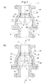
Fig. 1(a) and 1(b) are sectional side views of an embodiment of the present invention, showing its closed state and open state, respectively. -
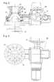
Fig. 2 is a plan view thereof. -
Fig. 3 is a front view thereof. -
Figs. 4(a), 4(b) and 4(c) are perspective views of a valve body and a valve seat of the embodiment, showing their positional relationship while the valve is closed (Fig. 4(a) ) and while the valve is open (Figs. 4(b) and 4(c) ). -
Fig. 5 shows how the valve is opened and closed. -
Fig. 6(a) and 6(b) are perspective views of valve bodies of different embodiments. -
Fig. 7 is a front view of a conventional powder valve of the ball valve type. -
Fig. 8 is a front view of a conventional segment ball valve. -
- 1, 21.
- Valve casing
- 2, 22.
- Valve body
- 3, 23.
- Valve seat
- 4, 24.
- Gap
- 5, 25.
- Valve shaft
- 6, 26.
- Communication hole
- 7.
- Gas injection hole
- 8.
- Operating member
- 10, 20.
- Powder valve
- 11.
- Inlet port
- 12.
- Outlet port
- 13, 27.
- Spherical surface
- 28.
- Ridgeline
- 29.
- Chamfer
- 22a.
- Front side
- 22b.
- Back side
- p.
- Central axis of the valve shaft
- q.
- Central axis of the communication hole
- Now the first embodiment is described with reference to
Figs. 1 to 5 . This embodiment is avalve 20 for powder provided in a transportation line for powder, such as a pipeline for pressure-feeding powder of natural gas hydrate. - As shown in
Fig. 1 , thevalve 20 comprises avalve casing 21 having aninlet port 11 and anoutlet port 12, and avalve body 22 mounted in thevalve casing 21 and supported by avalve shaft 25 so as to be rotatable about theshaft 25. - As shown in
Figs. 4(a) to 4(c) , thevalve body 22 is a substantially hemispherical member formed by forming astraight communication hole 26 having a circular cross-section in a spherical member whose section is completely circular when taken along any plane, and then by removing about half the spherical member on one side of thecommunication hole 26 such that thecommunication hole 26 is open at abackside 22b, i.e. a surface of thehemispherical valve body 22 formed by removing half the spherical member, over the entire length of thecommunication hole 26. - The
valve casing 21 has anannular valve seat 23 at theinlet port 11 that faces toward theoutlet port 12. Thus, when thefront surface 22a, i.e. thespherical surface 27, of thevalve body 22 faces toward thevalve seat 23, thespherical surface 27 liquid-tightly contact thevalve seat 23 over the entire circumference thereof. In this state, thevalve 20 for powder is closed (as shown inFigs. 1(a) and4(a) ). - The
valve shaft 25 has a central axis p that intersects the central axis q of thecommunication hole 26 at a right angle at the center ofspherical surface 27. When thevalve body 22 is at the position shown by solid line or phantom line inFig. 1(b) , the powder valve is in the open position whereinlet port 11 communicates with theoutlet port 12 through the communication hole 26 (seeFigs. 4(b) and 4(c) ).
Thus, thispowder valve 20 is moved into the open position by rotating thevalve body 22 about thevalve shaft 25 by 90 degrees from the closed position. - As shown in
Fig. 4(a) , thespherical surface 27 is defined by aridgelines 28 in the form of a sharp edges located near its portion in abutment with thevalve seat 23 when thevalve body 22 is in the closed position. As shown inFig. 4(c) , chamfers 29 are defined between thespherical surface 27 and the inner periphery of thecommunication hole 26 at portions near thevalve shaft 25. - The inner periphery of the
valve casing 21 has aspherical surface 13 extending along thespherical surface 27 of thevalve body 22 from thevalve seat 23 to theoutlet port 12. In the open position, agap 24 exists between thespherical surface 13 on the inner periphery of thevalve casing 21 and thespherical surface 27 of thevalve body 22. The width of thegap 24 gradually increases from thevalve seat 23 toward theoutlet port 12. - Now the operation of this powder valve is described. In the closed poison shown in
Fig. 1(a) , an operating member 8 (seeFigs. 2 and 3 ) operatively coupled to thevalve shaft 25 is turned, thevalve body 22 rotates about thevalve shaft 25 to an open position shown e.g. by the solid line inFig. 1(b) .
In this open position, powder introduced through theinlet port 11 of thevalve casing 21 mostly flows through thecommunication hole 26 in thevalve body 22 into the outlet port (as shown by arrows A and B inFig. 1(b) ). - Since the
spherical surface 13 on the inner periphery of thevalve casing 21 is a concave spherical surface, in the open position, powder tends to gradually adhere to thespherical surface 13, especially to its portion corresponding to the back 22b of thevalve body 22, as shown e.g. inFig. 5(a) .
But since thecommunication hole 26 is open to the above portion of thespherical surface 13 over the entire length of thecommunication hole 26, most of the powder adhered to thespherical surface 13 is guided downstream by the flow of the powder. This keeps the amount of powder adhered to thespherical surface 13 to a low level at all times. - When the operating member 8 (see
Figs. 2 and 3 ) is turned in the opposite direction to the above, thevalve body 22 is rotated about thevalve shaft 25 to the closed position shown inFig. 1(a) and then to another position shown by phantom line inFig. 1(b) . - When the
valve body 22 rotates as shown by the arrows C and D inFig. 5(a) , powder adhered to the inner surface of thevalve casing 21 is pushed by theedgy ridgeline 28 of thevalve 22 as shown inFig. 5(b) and is gradually guided downstream away from thevalve seat 23. Since theridgelines 28 are edgy, they can effectively scrape off powder. Since thevalve body 22 is hemispherical, eachridgeline 28 can scrape a larger area of thespherical surface 13 when thevalve body 22 rotates about thevalve shaft 25. This makes it possible to further efficiently scrape off powder. - Since the
gap 24 between thespherical surface 27 of thevalve body 22 and thespherical surface 13 on the inner periphery of thevalve casing 21 expands gradually as it is farther away from thevalve seat 23, even though the powder scraped off as thevalve body 22 rotates may collect into a large mass as shown inFig. 5(c) , such powder will never interfere with the rotation of thevalve body 22, and can be smoothly guided downstream and discharged. - By repeatedly moving the vale body between the position shown by solid line in
Fig. 1(b) and the position shown by phantom line inFig. 1(b) , it is possible to remove powder collected on the inner periphery of thevalve casing 21 on both sides of thevalve shaft 25.
In order to minimize the amount of power that adheres to the inner periphery of thevalve casing 21, as shown inFig. 1 , thespherical surface 13 of thevalve casing 21 where thevalve body 22 is mounted is smoothly connected to the inner periphery of theoutlet port 12 through an arcuate portion (indicated by the letter R) extending over the entire circumference. - In the embodiment, the
valve body 22 is hemispherical. But it may be in any other shape. For example, avalve body 22 shown inFig. 6(a) may be used which is nearer in shape to a sphere than thevalve body 22 of the above embodiment. Or avalve body 22 shown inFig. 6(b) may be used which is substantially completely spherical. Although not shown inFigs. 6(a) and 6(b) , chamfers 29 may be provided in either of the embodiments ofFigs. 6(a) and 6(b) .
In these embodiments too, since acommunication hole 26 is formed in thevalve body 22 that opens at thebackside 22b of thevalve body 22 over the entire length of thehole 26, power can be removed as effectively as in the first embodiment. Thevalve body 22 may be formed based not on a sphere but on an ellipsoid.
Claims (2)
- A valve for powder comprising a valve casing 21, a valve shaft 25, a valve body 22 mounted in the valve casing 21 and rotatably supported by the valve shaft 25, said valve casing 21 having an inlet port 11, and an annular valve seat 23 provided at the inlet port 11 of the valve casing 21, wherein said valve body 22 has a spherical outer surface 27 configured to be brought into contact with the valve seat 23 over the entire circumference of the valve seat 23 when the valve body 22 is in a closed position, wherein said valve body 22 is formed with a communication hole 26 extending in a direction perpendicular to an axis p of the valve shaft 25, wherein when the valve body 22 is rotated about the valve shaft 25 in either of two opposite directions from the closed position, the valve is configured to open through the communication hole 26, and wherein the communication hole 26 is open at its portion opposite to its side facing the valve seat 23 in the closed position, over an entire length of the communication hole 26.
- The valve for powder of claim 1 wherein the valve body 22 is hemispherical.
Applications Claiming Priority (1)
| Application Number | Priority Date | Filing Date | Title |
|---|---|---|---|
| PCT/JP2009/056105 WO2010109623A1 (en) | 2009-03-26 | 2009-03-26 | Valve for powder |
Publications (1)
| Publication Number | Publication Date |
|---|---|
| EP2412653A1 true EP2412653A1 (en) | 2012-02-01 |
Family
ID=42780332
Family Applications (1)
| Application Number | Title | Priority Date | Filing Date |
|---|---|---|---|
| EP09842237A Withdrawn EP2412653A1 (en) | 2009-03-26 | 2009-03-26 | Valve for powder |
Country Status (4)
| Country | Link |
|---|---|
| US (1) | US20120037833A1 (en) |
| EP (1) | EP2412653A1 (en) |
| BR (1) | BRPI0924486A2 (en) |
| WO (1) | WO2010109623A1 (en) |
Cited By (1)
| Publication number | Priority date | Publication date | Assignee | Title |
|---|---|---|---|---|
| IT201800010645A1 (en) * | 2018-11-28 | 2020-05-28 | Pirelli | INGREDIENT DOSING DEVICE FOR COMPOUNDS IN PARTICULAR FOR TIRES |
Families Citing this family (4)
| Publication number | Priority date | Publication date | Assignee | Title |
|---|---|---|---|---|
| US9791054B2 (en) * | 2014-11-18 | 2017-10-17 | Saudi Arabian Oil Company | Isolatable non-slam piston check valve |
| JP6590734B2 (en) * | 2016-02-29 | 2019-10-16 | 三菱重工エンジン&ターボチャージャ株式会社 | Rotary valve device, supercharger, and multistage supercharging system |
| AU2017363262B2 (en) * | 2016-11-22 | 2021-02-11 | Fluid Handling Llc | Combination of isolation valve and check valve with integrated flow rate, pressure and/or temperature measurement and field configurability |
| US10591069B2 (en) * | 2017-10-12 | 2020-03-17 | Schaeffler Technologies AG & Co. KG | Compact rotary valve body for coolant control valve |
Family Cites Families (14)
| Publication number | Priority date | Publication date | Assignee | Title |
|---|---|---|---|---|
| US3191906A (en) * | 1962-06-18 | 1965-06-29 | Fisher Governor Co | Flow control valve with a v-shaped opening |
| JPS5322811Y2 (en) * | 1972-09-14 | 1978-06-14 | ||
| US4822000A (en) * | 1987-08-24 | 1989-04-18 | Rockford Controls Corporation | Eccentric segmented ball valves |
| JP2560898Y2 (en) * | 1990-06-12 | 1998-01-26 | 日立バルブ 株式会社 | Ball valve |
| US5618026A (en) * | 1995-02-13 | 1997-04-08 | General Signal Corporation | Hybrid rotary control valve assembly |
| US6378842B1 (en) * | 2000-07-20 | 2002-04-30 | Delaware Capital Formation, Inc. | V-ball control valve |
| US7484710B2 (en) * | 2002-03-19 | 2009-02-03 | Fisher Controls International Llc | Fluid flow control valve with high temperature bi-directional shutoff |
| US6974121B2 (en) * | 2002-03-19 | 2005-12-13 | Fisher Controls International, Inc. | Fluid flow control valve with bi-directional shutoff |
| US6981691B2 (en) * | 2003-10-17 | 2006-01-03 | Dresser, Inc. | Dual segment ball valve |
| US8113484B2 (en) * | 2007-09-06 | 2012-02-14 | Fisher Controls International Llc | High temperature ball valve seal |
| US8720854B2 (en) * | 2010-04-30 | 2014-05-13 | Fisher Controls International Llc | Floating ball valve seal with dynamic C-seal and static C-seal |
| US8496226B2 (en) * | 2010-04-30 | 2013-07-30 | Fisher Controls International Llc | Floating ball valve seal with bellows and C-seal |
| US8733733B2 (en) * | 2010-04-30 | 2014-05-27 | Fisher Controls International Llc | Sleeve seal assembly and rotary valve having sleeve seal assembly |
| TW201226751A (en) * | 2010-12-29 | 2012-07-01 | Zipson Steel Ind Co Ltd | Arc valve |
-
2009
- 2009-03-26 WO PCT/JP2009/056105 patent/WO2010109623A1/en not_active Ceased
- 2009-03-26 EP EP09842237A patent/EP2412653A1/en not_active Withdrawn
- 2009-03-26 BR BRPI0924486A patent/BRPI0924486A2/en not_active IP Right Cessation
- 2009-03-26 US US13/202,778 patent/US20120037833A1/en not_active Abandoned
Non-Patent Citations (1)
| Title |
|---|
| See references of WO2010109623A1 * |
Cited By (2)
| Publication number | Priority date | Publication date | Assignee | Title |
|---|---|---|---|---|
| IT201800010645A1 (en) * | 2018-11-28 | 2020-05-28 | Pirelli | INGREDIENT DOSING DEVICE FOR COMPOUNDS IN PARTICULAR FOR TIRES |
| WO2020109992A1 (en) * | 2018-11-28 | 2020-06-04 | Pirelli Tyre S.P.A. | Metering apparatus for ingredients of compounds, in particular for tyres |
Also Published As
| Publication number | Publication date |
|---|---|
| WO2010109623A1 (en) | 2010-09-30 |
| BRPI0924486A2 (en) | 2016-02-16 |
| US20120037833A1 (en) | 2012-02-16 |
Similar Documents
| Publication | Publication Date | Title |
|---|---|---|
| EP2412653A1 (en) | Valve for powder | |
| US6981691B2 (en) | Dual segment ball valve | |
| CA2559970A1 (en) | Butterfly valve assembly with improved flow characteristics | |
| WO2012134949A2 (en) | Valve with dual rotation valve member | |
| EP3685081B1 (en) | Control valve with guide vane | |
| EP3695146B1 (en) | Valve and closure member | |
| EP3396219B1 (en) | Valves | |
| CN114321426B (en) | Plug valve and water air conditioner | |
| JP6122665B2 (en) | Channel switching device | |
| US7490627B2 (en) | Butterfly valve with water-filling function | |
| EP1815171B1 (en) | Plug valve with improved flow capacity | |
| US7404543B2 (en) | Slow closing actuator and valve | |
| US20200284357A1 (en) | Eccentric rotary valve | |
| US20130247861A1 (en) | Exhaust gas recirculation valve | |
| CN118654141B (en) | A ball valve | |
| US20040183046A1 (en) | Anti-scaling control element for a rotary control valve | |
| JP4086495B2 (en) | Butterfly valve with constant flow rate filling function | |
| WO2010117361A1 (en) | Fluid control valve | |
| JP2015203444A (en) | butterfly valve | |
| JP2014101988A (en) | Flow rate adjustment type rotary valve | |
| EP2696121B1 (en) | Shutoff valve with anti freeze system | |
| CN109312872B (en) | Valve assembly and method of operating the same | |
| JP3679745B2 (en) | Gas cock ball switching valve | |
| KR101962864B1 (en) | Ball Valve | |
| JP2009085388A (en) | Valve for powder |
Legal Events
| Date | Code | Title | Description |
|---|---|---|---|
| PUAI | Public reference made under article 153(3) epc to a published international application that has entered the european phase |
Free format text: ORIGINAL CODE: 0009012 |
|
| 17P | Request for examination filed |
Effective date: 20111021 |
|
| AK | Designated contracting states |
Kind code of ref document: A1 Designated state(s): AT BE BG CH CY CZ DE DK EE ES FI FR GB GR HR HU IE IS IT LI LT LU LV MC MK MT NL NO PL PT RO SE SI SK TR |
|
| DAX | Request for extension of the european patent (deleted) | ||
| STAA | Information on the status of an ep patent application or granted ep patent |
Free format text: STATUS: THE APPLICATION HAS BEEN WITHDRAWN |
|
| 18W | Application withdrawn |
Effective date: 20130319 |