EP2412649A1 - Articulated flat surface conveyor belt with side link - Google Patents
Articulated flat surface conveyor belt with side link Download PDFInfo
- Publication number
- EP2412649A1 EP2412649A1 EP11175475A EP11175475A EP2412649A1 EP 2412649 A1 EP2412649 A1 EP 2412649A1 EP 11175475 A EP11175475 A EP 11175475A EP 11175475 A EP11175475 A EP 11175475A EP 2412649 A1 EP2412649 A1 EP 2412649A1
- Authority
- EP
- European Patent Office
- Prior art keywords
- conveyor belt
- side link
- product
- belt according
- assembly
- Prior art date
- Legal status (The legal status is an assumption and is not a legal conclusion. Google has not performed a legal analysis and makes no representation as to the accuracy of the status listed.)
- Granted
Links
- 235000013305 food Nutrition 0.000 claims abstract description 20
- 230000000712 assembly Effects 0.000 claims abstract description 18
- 238000000429 assembly Methods 0.000 claims abstract description 18
- 230000007704 transition Effects 0.000 claims abstract description 6
- 239000010935 stainless steel Substances 0.000 claims description 7
- 229910001220 stainless steel Inorganic materials 0.000 claims description 7
- 239000000463 material Substances 0.000 claims description 4
- 230000032258 transport Effects 0.000 description 10
- 238000006073 displacement reaction Methods 0.000 description 8
- 230000008014 freezing Effects 0.000 description 8
- 238000007710 freezing Methods 0.000 description 8
- 238000004140 cleaning Methods 0.000 description 6
- 230000005484 gravity Effects 0.000 description 3
- 229910000831 Steel Inorganic materials 0.000 description 2
- 230000001419 dependent effect Effects 0.000 description 2
- 230000000694 effects Effects 0.000 description 2
- 238000007654 immersion Methods 0.000 description 2
- 238000000034 method Methods 0.000 description 2
- 230000004048 modification Effects 0.000 description 2
- 238000012986 modification Methods 0.000 description 2
- 238000004806 packaging method and process Methods 0.000 description 2
- 238000000926 separation method Methods 0.000 description 2
- 239000010959 steel Substances 0.000 description 2
- 229910045601 alloy Inorganic materials 0.000 description 1
- 239000000956 alloy Substances 0.000 description 1
- 230000015572 biosynthetic process Effects 0.000 description 1
- 238000010276 construction Methods 0.000 description 1
- 239000000356 contaminant Substances 0.000 description 1
- 238000011109 contamination Methods 0.000 description 1
- 238000001035 drying Methods 0.000 description 1
- 230000007246 mechanism Effects 0.000 description 1
- 230000008569 process Effects 0.000 description 1
- 238000005406 washing Methods 0.000 description 1
Images

Classifications
-
- B—PERFORMING OPERATIONS; TRANSPORTING
- B65—CONVEYING; PACKING; STORING; HANDLING THIN OR FILAMENTARY MATERIAL
- B65G—TRANSPORT OR STORAGE DEVICES, e.g. CONVEYORS FOR LOADING OR TIPPING, SHOP CONVEYOR SYSTEMS OR PNEUMATIC TUBE CONVEYORS
- B65G17/00—Conveyors having an endless traction element, e.g. a chain, transmitting movement to a continuous or substantially-continuous load-carrying surface or to a series of individual load-carriers; Endless-chain conveyors in which the chains form the load-carrying surface
- B65G17/06—Conveyors having an endless traction element, e.g. a chain, transmitting movement to a continuous or substantially-continuous load-carrying surface or to a series of individual load-carriers; Endless-chain conveyors in which the chains form the load-carrying surface having a load-carrying surface formed by a series of interconnected, e.g. longitudinal, links, plates, or platforms
- B65G17/063—Conveyors having an endless traction element, e.g. a chain, transmitting movement to a continuous or substantially-continuous load-carrying surface or to a series of individual load-carriers; Endless-chain conveyors in which the chains form the load-carrying surface having a load-carrying surface formed by a series of interconnected, e.g. longitudinal, links, plates, or platforms the load carrying surface being formed by profiles, rods, bars, rollers or the like attached to more than one traction element
-
- B—PERFORMING OPERATIONS; TRANSPORTING
- B65—CONVEYING; PACKING; STORING; HANDLING THIN OR FILAMENTARY MATERIAL
- B65G—TRANSPORT OR STORAGE DEVICES, e.g. CONVEYORS FOR LOADING OR TIPPING, SHOP CONVEYOR SYSTEMS OR PNEUMATIC TUBE CONVEYORS
- B65G17/00—Conveyors having an endless traction element, e.g. a chain, transmitting movement to a continuous or substantially-continuous load-carrying surface or to a series of individual load-carriers; Endless-chain conveyors in which the chains form the load-carrying surface
- B65G17/30—Details; Auxiliary devices
- B65G17/38—Chains or like traction elements; Connections between traction elements and load-carriers
- B65G17/42—Attaching load carriers to traction elements
Definitions
- the present invention relates to a conveyor belt for transporting a product.
- Certain conveying operations for transporting product require that individual products be spaced apart from adjacent products to prevent contact with each other when entering a freezing system such as an immersion, tunnel or spiral freezing system.
- the known conveyor belts are not able to provide for fully individual quick frozen (IQF) product without additional actuation means to prevent adjacent products from contacting each other and "clumping", unless the products are initially separated from each other prior to entering the freezing system.
- IQF quick frozen
- an object of the present invention is to prevent products, in particular food products, for example fully individual quick frozen (IQF) products, from contacting each other when being processed with a conveyor belt.
- IQF fully individual quick frozen
- the present embodiments include an articulated flat surface conveyor belt with side link, in particular a conveyor belt surface consisting of a plurality of adjacent sections, each of which are moveable with respect to each other, which in turn provides for movement of the products and separation of same from each other as the products are conveyed on the belt surface.
- Products such as food products, are therefore frozen individually, as opposed to freezing in clumps of the product.
- the surface of the conveyor belt embodiments herein allow for freezing or crust freezing of food products having a wet surface without formation of belt marks on a surface of the products.
- the arrangement and displacement of the sections of the conveyor belt provides for quick, easy sanitation of the belt, because there are fewer harborage points at the belt where food product can be trapped.
- the product support surface of the belt can be displaced from the conveying base or assembly of the belt during cleaning to allow more space and therefore easier and more complete sanitation of the spaces and areas between and among the transport assembly and the product support surface of the belt.
- the plurality of transport assemblies are arranged adjacent each other such that a plurality of the product support members provide an upper surface upon which the product is conveyed.
- the side link assembly comprises a pair of side links, each one of the side links comprising a central aperture for receiving a corresponding end of the actuation member.
- the side link assembly comprises a pair of holes disposed at opposed sides of the central aperture for receiving corresponding ends of the support assembly.
- the actuation member is displacably moveable in the central aperture.
- the central aperture is oblong-shaped.
- the support assembly comprises a pair of pins.
- the plurality of transport assemblies are arranged with respect to each other to transition around a drum with the actuation member facing the drum.
- each one of the plurality of transport assemblies is movable independently of other of the transport assemblies.
- the product support member is constructed from material selected from stainless steel, plastic, and combinations thereof.
- the product support member is constructed as a longitudinal member.
- the actuation member is manufactured from stainless steel.
- the actuation member is constructed as a pin.
- the side link is U-shaped.
- the product comprises a food product.
- the present invention finally relates to the use of a conveyor belt as described above for transporting products, in particular food products, for example fully individual quick frozen (IQF) products, without contacting each other.
- products in particular food products, for example fully individual quick frozen (IQF) products, without contacting each other.
- IQF fully individual quick frozen
- the present articulated flat surface conveyor belt embodiments with side link permit movement of a section of a belt surface with respect to adjacent sections of the belt surface, which in turn provides for movement of the product along the belt surface and effective cleaning of the belt.
- the belt surface may be displaced, and such displacement also displaces the food product on the belt surface, such that adjacent food product does not contact each other, which avoids unacceptable "clumping" of the individual food products. Displacement of the belt surface also provides for more effective and efficient cleaning of the conveyor belt.
- a portion of a conveyor belt embodiment 10 which includes a conveyor belt surface shown generally at 12.
- the conveyor belt embodiment 10 consists of a plurality of transport assemblies which coact with each other.
- Each one of the transport assemblies includes a longitudinal member 14, a pin 16, a pair of side links 20, 21 and a pair of rods 40, 42.
- the conveyor belt transports products (not shown) such as for example food products.
- the conveyor belt surface 12 (for the sake of brevity referred to as the "conveyor surface") consists of a plurality of the longitudinal members 14 as product support surfaces (each one for the sake of brevity referred to as a "support members").
- Each of the support members 14 may be manufactured from stainless steel or plastic materials for example. That is, each one of the support members 14 may be formed from one piece of plastic or one piece of stainless steel.
- the support members 14 when disposed adjacent to each other provide the conveyor surface 12.
- Each support member 14 is constructed as a longitudinal member supported upon a pin 16 which extends through or underneath the support member 14 as will be explained hereinafter.
- the pins 16 may be manufactured from stainless steel.
- the support members 14 each have opposed longitudinal edges 18, 19 which abut a corresponding longitudinal edge 18, 19 as the case may be, of an adjacent support member 14.
- a side link 20 is shown as U-shaped and constructed to coact with an adjacent side link 21 for actuation of the conveyor belt 10 during processing and cleaning modes.
- Each side link 20, 21 includes a pair of arms 22, 24 interconnected by a base portion 26.
- Each one of the arms 22, 24 is provided with a corresponding oblong-shaped central aperture 28, 30, respectively.
- a pair of holes 32, 34 in the arm 22 are each disposed at an opposed side of the central aperture 28, while a pair of holes 36, 38 in the arm 24 are each disposed at an opposed side of the central aperture 30.
- the holes 32, 34, 36, 38 may be circular in shape.
- the central apertures 28, 30 are constructed and arranged to receive a corresponding one of the pins 16 as shown for example in FIG. 2 .
- the side links 20, 21 may be constructed from steel or other alloy.
- Distance D1 represents a distance of the space between the arms 22, 24.
- Distance D2 represents a height of each one of the central apertures 28, 30. The distance D1 is sufficient to permit the base portion 26 and corresponding arms 22, 24 of an adjacent side link 20 (or 21) to be received into the space, base 26 first, between the arms 22, 24 of the side link 20 (or 21).
- FIG. 2 and to FIG. 3 it is shown how the base portion 26 of a side link 20 can be received between the arms 22, 24 of an adjacent side link 20 such that the holes 32, 36 of one of the side links 20 come into registration with the holes 34, 38 of the adjacent receiving side link.
- each one of the support members 14 rests upon a corresponding pair of rods 40, 42.
- the rods 40, 42 may be manufactured from steel.
- the rods 40, 42 each extend through corresponding apertures 32, 36 and 34, 38 for each one of the side links 20, 21.
- the rods 40, 42 extend underneath the support members 14 to support same with respect to a corresponding one of the side links 20, 21.
- each one of the support members 14 can be freely and individually displaced with respect to adjacent and other ones of the support members 14 because the pin 16 has freedom of movement to be displaced in the central apertures 28, 30 and therefore, displace the conveyor belt surface 12 as well.
- the arrangement of the side links 20, 21 is at both opposed sides of the conveyor belt 10. It can be seen then, that selective displacement of the pins 16 can result in selective displacement of the support members 14 to provide for a vibratory or articulating conveyor surface 12, if required, during movement of the conveyor belt 10. Such displacement of the support members 14 also provides for easier and more thorough cleaning of the members 14 and other elements of the conveyor belt embodiment 10, as discussed below.
- An underlying surface of the support members 14 may be constructed and arranged with a beveled or contoured portion for receiving a corresponding one of the rods 40, 42.
- FIG. 1 , FIG. 2 and FIG. 4 the conveyor belt 10 is moving in the direction of arrow 44.
- the conveyor surface 12 is shown with the opposed longitudinal edges 18, 19 of support members 14 abutting each other so that a smooth, nonporous conveyor surface 12 is provided for the conveyor belt 10. This occurs at least at an upper run or top tier of the conveyor belt run.
- the pins 16 are displaced in the central apertures 28, 30 of the side links 20, 21 to facilitate spacing 23 or a space between and among the support members 14 to negotiate the turn.
- the displacement of the support members 14 can be under the effect of gravity or by mechanical displacement means (not shown).
- the product such as food product
- processing such as for example packaging, or for further treatment prior to packaging.
- Another example of further processing is to crust-freeze the product (now having no belt markings) for subsequent freezing in a final-freeze process.
- the use of the plastic support members 14 substantially reduces if not eliminates product sticking to the belt.
- the product may be further processed in a belt press to obtain uniform product thickness for a plurality of products being processed.
- a device or mechanism (not shown) has tripped or actuated the pins 16 such that they are or remain displaced in their corresponding central apertures 28, 30 with the longitudinal edges 18, 19 of adjacent support members 14 moved apart from one another to thereby provide the space 23 between adjacent support members 14.
- the space facilitates cleaning of the support members 14 of any extraneous food product or contaminate material.
- the spacing 23 also promotes subsequent drying after washing or rinsing of the support members 14 during a return run of the conveyor belt 10 to, for example, retrieve subsequent food product.
- a dryer device or blower may be used to direct clean, dry air in the direction of arrow 45 after washdown to dry the support members 14.
- Each one of the support members 14 can articulate or be displaced at different intervals from adjacent or other support members 14 by applying force to either the individual support member 14 or the pin 16.
- the side links 20, 21 and the rods 40, 42 drive and support the support members 14. An additional drive system is not needed to contact and displace the pins 16 and hence the support members 14.
- the construction of the plurality of transport assemblies is such that when the transport assemblies transition around a drum (not shown) or sprocket (not shown) in a manner similar to that shown in FIG. 4 , the pin 16 (actuation member) will face the drum or sprocket.
Landscapes
- Engineering & Computer Science (AREA)
- Mechanical Engineering (AREA)
- Chain Conveyers (AREA)
Abstract
- a side link assembly (20, 21);
- a support assembly (40, 42) connected to the side link assembly (20, 21);
- a product support member (14) supported on the support assembly (40, 42) and adapted for displaceable movement with respect to the side link assembly (20, 21) and the support assembly (40, 42); and
- an actuation member (16) supporting the product support member (14) with respect to the side link assembly (20, 21) and the support assembly (40, 42), the actuation member (16) coacting with the side link assembly (20, 21) for moving the product support member (14) between a first position wherein the product support member (14) is in a first plane of travel with respect to the side link assembly (20, 21) for conveying the product, and a second position wherein the product support member (14) transitions to a second plane of travel with respect to the side link assembly (20, 21) different from the first plane of travel for providing a space between the product support member (14) of each one of the plurality of transport assemblies.
Description
- The present invention relates to a conveyor belt for transporting a product.
- Certain conveying operations for transporting product, such as food products, require that individual products be spaced apart from adjacent products to prevent contact with each other when entering a freezing system such as an immersion, tunnel or spiral freezing system.
- When products, such as food products, are to be processed in an immersion, tunnel or spiral freezing system, the known conveyor belts are not able to provide for fully individual quick frozen (IQF) product without additional actuation means to prevent adjacent products from contacting each other and "clumping", unless the products are initially separated from each other prior to entering the freezing system.
- The separation of the food products so as not to contact each other requires additional labor or other apparatus when processing the food product with known belts. Known conveyor system structures also provide many "harborage points" for undesirable matter and contaminants.
- Therefore, producing IQF food product with known systems entails additional labor and/or processing equipment, and increases the chance of contamination.
- Starting from the disadvantages and shortcomings as described above and taking the prior art as discussed into account, an object of the present invention is to prevent products, in particular food products, for example fully individual quick frozen (IQF) products, from contacting each other when being processed with a conveyor belt.
- This object is accomplished by a conveyor belt comprising the features of claim 1. Advantageous embodiments and expedient improvements of the present invention are disclosed in the dependent claims.
- The present embodiments include an articulated flat surface conveyor belt with side link, in particular a conveyor belt surface consisting of a plurality of adjacent sections, each of which are moveable with respect to each other, which in turn provides for movement of the products and separation of same from each other as the products are conveyed on the belt surface. Products, such as food products, are therefore frozen individually, as opposed to freezing in clumps of the product.
- The surface of the conveyor belt embodiments herein allow for freezing or crust freezing of food products having a wet surface without formation of belt marks on a surface of the products.
- In addition, the arrangement and displacement of the sections of the conveyor belt provides for quick, easy sanitation of the belt, because there are fewer harborage points at the belt where food product can be trapped.
- Moreover, the product support surface of the belt can be displaced from the conveying base or assembly of the belt during cleaning to allow more space and therefore easier and more complete sanitation of the spaces and areas between and among the transport assembly and the product support surface of the belt.
- According to an advantageous embodiment of the present invention, the plurality of transport assemblies are arranged adjacent each other such that a plurality of the product support members provide an upper surface upon which the product is conveyed.
- According to an expedient embodiment of the present invention, the side link assembly comprises a pair of side links, each one of the side links comprising a central aperture for receiving a corresponding end of the actuation member.
- According to a favoured embodiment of the present invention, the side link assembly comprises a pair of holes disposed at opposed sides of the central aperture for receiving corresponding ends of the support assembly.
- According to a preferred embodiment of the present invention, the actuation member is displacably moveable in the central aperture.
- According to an advantageous embodiment of the present invention, the central aperture is oblong-shaped.
- According to an expedient embodiment of the present invention, the support assembly comprises a pair of pins.
- According to a favoured embodiment of the present invention, the plurality of transport assemblies are arranged with respect to each other to transition around a drum with the actuation member facing the drum.
- According to a preferred embodiment of the present invention, each one of the plurality of transport assemblies is movable independently of other of the transport assemblies.
- According to an advantageous embodiment of the present invention, the product support member is constructed from material selected from stainless steel, plastic, and combinations thereof.
- According to an expedient embodiment of the present invention, the product support member is constructed as a longitudinal member.
- According to a favoured embodiment of the present invention, the actuation member is manufactured from stainless steel.
- According to a preferred embodiment of the present invention, the actuation member is constructed as a pin.
- According to an advantageous embodiment of the present invention, the side link is U-shaped.
- According to an expedient embodiment of the present invention, the product comprises a food product.
- The present invention finally relates to the use of a conveyor belt as described above for transporting products, in particular food products, for example fully individual quick frozen (IQF) products, without contacting each other.
- For a more complete understanding of the present embodiments and as already discussed above, there are several options to embody as well as to improve the teaching of the present invention in an advantageous manner. To this aim, reference may be made to the claims dependent on claim 1; further improvements, features and advantages of the present invention are explained below in more detail with reference to preferred embodiments by way of non-limiting example and to the appended drawing figures taken in conjunction with the description of the embodiments, of which:
- FIG. 1
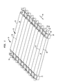
- shows a section view of a conveyor belt according to an embodiment of the present invention, being operated according to the method of the present invention;
- FIG. 2
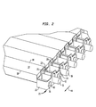
- shows an enlarged portion of the section of
FIG. 1 ; - FIG. 3
- shows a side link of the conveyor belt embodiment of
FIG. 1 ; and - FIG. 4
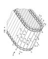
- shows a conveyor belt embodiment executing a turn.
- The present articulated flat surface conveyor belt embodiments with side link permit movement of a section of a belt surface with respect to adjacent sections of the belt surface, which in turn provides for movement of the product along the belt surface and effective cleaning of the belt. The belt surface may be displaced, and such displacement also displaces the food product on the belt surface, such that adjacent food product does not contact each other, which avoids unacceptable "clumping" of the individual food products. Displacement of the belt surface also provides for more effective and efficient cleaning of the conveyor belt.
- Referring to
FIG. 1 ,FIG. 2 ,FIG. 3 , there is shown a portion of aconveyor belt embodiment 10 which includes a conveyor belt surface shown generally at 12. Theconveyor belt embodiment 10 consists of a plurality of transport assemblies which coact with each other. Each one of the transport assemblies includes alongitudinal member 14, apin 16, a pair ofside links rods - The conveyor belt surface 12 (for the sake of brevity referred to as the "conveyor surface") consists of a plurality of the
longitudinal members 14 as product support surfaces (each one for the sake of brevity referred to as a "support members"). Each of thesupport members 14 may be manufactured from stainless steel or plastic materials for example. That is, each one of thesupport members 14 may be formed from one piece of plastic or one piece of stainless steel. - The
support members 14 when disposed adjacent to each other provide theconveyor surface 12. Eachsupport member 14 is constructed as a longitudinal member supported upon apin 16 which extends through or underneath thesupport member 14 as will be explained hereinafter. Thepins 16 may be manufactured from stainless steel. Thesupport members 14 each have opposedlongitudinal edges longitudinal edge adjacent support member 14. - Referring in particular to
FIG. 3 , aside link 20 is shown as U-shaped and constructed to coact with anadjacent side link 21 for actuation of theconveyor belt 10 during processing and cleaning modes. Eachside link arms base portion 26. - Each one of the
arms central aperture holes arm 22 are each disposed at an opposed side of thecentral aperture 28, while a pair ofholes arm 24 are each disposed at an opposed side of thecentral aperture 30. Theholes - The
central apertures pins 16 as shown for example inFIG. 2 . The side links 20, 21 may be constructed from steel or other alloy. - Distance D1 represents a distance of the space between the
arms central apertures base portion 26 and correspondingarms base 26 first, between thearms - For example, referring to
FIG. 2 and toFIG. 3 , it is shown how thebase portion 26 of aside link 20 can be received between thearms holes holes - Still referring to
FIG. 2 and toFIG. 3 , each one of thesupport members 14 rests upon a corresponding pair ofrods rods rods corresponding apertures rods support members 14 to support same with respect to a corresponding one of the side links 20, 21. - Accordingly, while the plurality of
side links conveyor belt 10 are connected to each other by thepins support members 14 can be freely and individually displaced with respect to adjacent and other ones of thesupport members 14 because thepin 16 has freedom of movement to be displaced in thecentral apertures conveyor belt surface 12 as well. - As shown in
FIG. 1 , the arrangement of the side links 20, 21 is at both opposed sides of theconveyor belt 10. It can be seen then, that selective displacement of thepins 16 can result in selective displacement of thesupport members 14 to provide for a vibratory or articulatingconveyor surface 12, if required, during movement of theconveyor belt 10. Such displacement of thesupport members 14 also provides for easier and more thorough cleaning of themembers 14 and other elements of theconveyor belt embodiment 10, as discussed below. - An underlying surface of the
support members 14 may be constructed and arranged with a beveled or contoured portion for receiving a corresponding one of therods - ln
FIG. 1 ,FIG. 2 andFIG. 4 theconveyor belt 10 is moving in the direction ofarrow 44. - Referring to
FIG. 4 , theconveyor surface 12 is shown with the opposedlongitudinal edges support members 14 abutting each other so that a smooth,nonporous conveyor surface 12 is provided for theconveyor belt 10. This occurs at least at an upper run or top tier of the conveyor belt run. - As the
conveyor belt 10 transitions around a sprocket or wheel (not shown) to execute the turn shown inFIG. 4 , thepins 16 are displaced in thecentral apertures spacing 23 or a space between and among thesupport members 14 to negotiate the turn. The displacement of thesupport members 14 can be under the effect of gravity or by mechanical displacement means (not shown). - The product, such as food product, can be removed under the effective gravity from the
conveyor surface 12 for processing such as for example packaging, or for further treatment prior to packaging. Another example of further processing is to crust-freeze the product (now having no belt markings) for subsequent freezing in a final-freeze process. - The use of the
plastic support members 14 substantially reduces if not eliminates product sticking to the belt. The product may be further processed in a belt press to obtain uniform product thickness for a plurality of products being processed. - Still referring to
FIG. 4 , if not for gravity, a device or mechanism (not shown) has tripped or actuated thepins 16 such that they are or remain displaced in their correspondingcentral apertures longitudinal edges adjacent support members 14 moved apart from one another to thereby provide thespace 23 betweenadjacent support members 14. - The space facilitates cleaning of the
support members 14 of any extraneous food product or contaminate material. The spacing 23 also promotes subsequent drying after washing or rinsing of thesupport members 14 during a return run of theconveyor belt 10 to, for example, retrieve subsequent food product. - Although not shown, a dryer device or blower may be used to direct clean, dry air in the direction of
arrow 45 after washdown to dry thesupport members 14. - Each one of the
support members 14 can articulate or be displaced at different intervals from adjacent orother support members 14 by applying force to either theindividual support member 14 or thepin 16. The side links 20, 21 and therods support members 14. An additional drive system is not needed to contact and displace thepins 16 and hence thesupport members 14. - Force can be applied to an underlying portion of each of the
support members 14 to displace same along its line of travel. The force applied to thesupport members 14 will agitate the products so that they separate or remain separated from each other. Product that adheres to the belt will be dislodged from the belt under the effect of the force applied to the underside of thesupport members 14. - The construction of the plurality of transport assemblies is such that when the transport assemblies transition around a drum (not shown) or sprocket (not shown) in a manner similar to that shown in
FIG. 4 , the pin 16 (actuation member) will face the drum or sprocket. - lt will be understood that the embodiments described herein are merely exemplary, and that one skilled in the art may make variations and modifications without departing from the spirit and scope of the invention. All such variations and modifications are intended to be included within the scope of the invention as described and claimed herein. Further, all embodiments disclosed are not necessarily in the alternative, as various embodiments of the invention may be combined to provide the desired result.
-
- 10
- conveyor belt
- 12
- surface of
conveyor belt 10 - 14
- support members, in particular product support member or product support surface, for example longitudinal member
- 16
- actuation member, in particular pin
- 18
- first longitudinal edge of
product support member 14 - 19
- second longitudinal edge of
product support member 14 - 20
- side link assembly, in particular first side link of pair of
side links - 21
- side link assembly, in particular second side link of pair of
side links - 22
- first arm of pair of
arms side link - 23
- spacing or space between and among
adjacent support members 14 - 24
- second arm of pair of
arms side link - 26
- base portion for interconnecting pair of
arms - 28
- central aperture of
first arm 22 - 30
- central aperture of
second arm 24 - 32
- first hole of pair of
holes first arm 22 - 34
- second hole of pair of
holes first arm 22 - 36
- first hole of pair of
holes second arm 24 - 38
- second hole of pair of
holes second arm 24 - 40
- support assembly, in particular first rod of pair of
rods - 42
- support assembly, in particular second rod of pair of
rods - 44
- arrow defining direction of movement of
conveyor belt 10 - 45
- arrow defining direction of clean dry air
- D1
- distance of space between pair of
arms - D2
- height of
central apertures
Claims (15)
- A conveyor belt (10) for transporting a product, comprising a plurality of transport assemblies, each one of the plurality of transport assemblies comprising:- a side link assembly (20, 21);- a support assembly (40, 42) connected to the side link assembly (20, 21);- a product support member (14) supported on the support assembly (40, 42) and adapted for displaceable movement with respect to the side link assembly (20, 21) and the support assembly (40, 42); and- an actuation member (16) supporting the product support member (14) with respect to the side link assembly (20, 21) and the support assembly (40, 42), the actuation member (16) coacting with the side link assembly (20, 21) for moving the product support member (14) between a first position wherein the product support member (14) is in a first plane of travel with respect to the side link assembly (20, 21) for conveying the product, and a second position wherein the product support member (14) transitions to a second plane of travel with respect to the side link assembly (20, 21) different from the first plane of travel for providing a space between the product support member (14) of each one of the plurality of transport assemblies.
- The conveyor belt according to claim 1, wherein the plurality of transport assemblies are arranged adjacent each other such that a plurality of the product support members (14) provide an upper surface upon which the product is conveyed.
- The conveyor belt according to claim 1 or 2, wherein the side link assembly (20, 21) comprises a pair of side links (20, 21), each one of the side links (20, 21) comprising a central aperture (28, 30) for receiving a corresponding end of the actuation member (16).
- The conveyor belt according to claim 3, wherein the side link assembly (20, 21) comprises a pair of holes (32, 34, 36, 38) disposed at opposed sides of the central aperture (28, 30) for receiving corresponding ends of the support assembly (40, 42).
- The conveyor belt according to claim 3 or 4, wherein the actuation member (16) is displacably moveable in the central aperture (28, 30).
- The conveyor belt according to at least one of claims 3 to 5, wherein the central aperture (28, 30) is oblong-shaped.
- The conveyor belt according to at least one of claims 1 to 6, wherein the support assembly (40, 42) comprises a pair of pins.
- The conveyor belt according to at least one of claims 1 to 7, wherein the plurality of transport assemblies are arranged with respect to each other to transition around a drum with the actuation member (16) facing the drum.
- The conveyor belt according to at least one of claims 1 to 8, wherein each one of the plurality of transport assemblies is movable independently of other of the transport assemblies.
- The conveyor belt according to at least one of claims 1 to 9, wherein the product support member (14) is constructed from material selected from stainless steel, plastic, and combinations thereof.
- The conveyor belt according to at least one of claims 1 to 10, wherein the product support member (14) is constructed as a longitudinal member.
- The conveyor belt according to at least one of claims 1 to 11, wherein the actuation member (16) is manufactured from stainless steel.
- The conveyor belt according to at least one of claims 1 to 12, wherein the actuation member (16) is constructed as a pin.
- The conveyor belt according to at least one of claims 1 to 13, wherein the side link (20, 21) is U-shaped.
- The conveyor belt according to at least one of claims 1 to 14, wherein the product comprises a food product.
Priority Applications (1)
| Application Number | Priority Date | Filing Date | Title |
|---|---|---|---|
| PL11175475T PL2412649T3 (en) | 2010-07-27 | 2011-07-27 | Articulated flat surface conveyor belt with side link |
Applications Claiming Priority (1)
| Application Number | Priority Date | Filing Date | Title |
|---|---|---|---|
| US12/844,104 US8312989B2 (en) | 2010-07-27 | 2010-07-27 | Articulated flat surface conveyor belt with side link |
Publications (2)
| Publication Number | Publication Date |
|---|---|
| EP2412649A1 true EP2412649A1 (en) | 2012-02-01 |
| EP2412649B1 EP2412649B1 (en) | 2013-03-06 |
Family
ID=44543067
Family Applications (1)
| Application Number | Title | Priority Date | Filing Date |
|---|---|---|---|
| EP11175475A Not-in-force EP2412649B1 (en) | 2010-07-27 | 2011-07-27 | Articulated flat surface conveyor belt with side link |
Country Status (5)
| Country | Link |
|---|---|
| US (1) | US8312989B2 (en) |
| EP (1) | EP2412649B1 (en) |
| DK (1) | DK2412649T3 (en) |
| ES (1) | ES2405689T3 (en) |
| PL (1) | PL2412649T3 (en) |
Cited By (3)
| Publication number | Priority date | Publication date | Assignee | Title |
|---|---|---|---|---|
| EP3310179A1 (en) * | 2015-06-18 | 2018-04-25 | Teknologisk Institut | Food processing table or conveyor belt with a layer of solidified liquid such as an ice layer and method for producing such solidified liquid |
| US11565893B2 (en) | 2018-08-29 | 2023-01-31 | Laitram, L.L.C. | Ice-covered tray conveyor |
| WO2023140987A1 (en) * | 2022-01-21 | 2023-07-27 | Praxair Technology, Inc. | Apparatus and method for crust freezing |
Families Citing this family (7)
| Publication number | Priority date | Publication date | Assignee | Title |
|---|---|---|---|---|
| US20150326545A1 (en) * | 2014-05-06 | 2015-11-12 | Apple Inc. | Secure key rotation for an issuer security domain of an electronic device |
| US10118766B2 (en) * | 2016-03-10 | 2018-11-06 | Cambridge International, Inc. | Splice link for conveyor belt |
| US9809387B2 (en) * | 2016-03-14 | 2017-11-07 | Chuan Yang Foods Machine Co., Ltd. | Anti-sticking conveyor belt and conveyor strips of frying machine |
| DE102016105008B3 (en) * | 2016-03-17 | 2017-08-24 | Chuan Yang Foods Machine Co., Ltd. | Anti-stick conveyor belt and conveyor strip of a fryer |
| WO2020243131A1 (en) * | 2019-05-29 | 2020-12-03 | Laitram, L.L.C. | Modular slat conveyor belt |
| AU2021206819A1 (en) * | 2021-07-20 | 2023-02-09 | Apap and Grima Pty Ltd | Improved Conveyor System |
| GB2621365B (en) * | 2022-08-10 | 2024-08-14 | Pennine Industrial Equipment Ltd | Link for a Multi-Link Conveyor Chain |
Citations (3)
| Publication number | Priority date | Publication date | Assignee | Title |
|---|---|---|---|---|
| US3447668A (en) * | 1967-04-12 | 1969-06-03 | Eskimo Pie Corp | Conveyer |
| EP0002287A1 (en) * | 1977-11-26 | 1979-06-13 | TKV Transportanlagen- Konstruktions- und Vertriebs-Gesellschaft mbH | Plate belt conveyor |
| NL1030353C2 (en) * | 2005-11-04 | 2007-05-07 | Johannes Hermannus Joz Asbreuk | Portable floor for transporting goods, has transport chains with drives, and strips provided between transport chains, where each strip includes end linked to transport chains |
Family Cites Families (9)
| Publication number | Priority date | Publication date | Assignee | Title |
|---|---|---|---|---|
| US1285448A (en) * | 1918-03-28 | 1918-11-19 | Guss F Spooner | Screen. |
| US2666404A (en) * | 1951-02-13 | 1954-01-19 | Detroit Stoker Co | Stoker apparatus |
| US3985224A (en) * | 1975-03-17 | 1976-10-12 | U.M.E.C.-Boydell (Belting) Limited | Conveyor belt |
| US6607064B2 (en) * | 2002-01-11 | 2003-08-19 | Fujitec America Inc. | Shallow wellway moving walk |
| US7802675B2 (en) * | 2005-05-13 | 2010-09-28 | Ramsey Products Corporation | End protector link for conveyor chain |
| WO2007140242A2 (en) * | 2006-05-24 | 2007-12-06 | Span Tech Llc | Side-flexing conveyor chain with pivoting slats and related methods |
| ITMI20061395A1 (en) * | 2006-07-18 | 2008-01-19 | Tecno Pool Spa | CONVEYOR BELT OF A CHAIN CONVEYOR WITH INNOVATIVE DRIVING JERSEYS. |
| EP2346754B1 (en) * | 2008-10-31 | 2019-09-25 | Cambridge International, Inc. | Wire plate conveyor belt |
| US20120018281A1 (en) * | 2010-07-21 | 2012-01-26 | Mccormick Stephen A | Conveyor belt with articulating transport surface |
-
2010
- 2010-07-27 US US12/844,104 patent/US8312989B2/en not_active Expired - Fee Related
-
2011
- 2011-07-27 ES ES11175475T patent/ES2405689T3/en active Active
- 2011-07-27 PL PL11175475T patent/PL2412649T3/en unknown
- 2011-07-27 DK DK11175475.0T patent/DK2412649T3/en active
- 2011-07-27 EP EP11175475A patent/EP2412649B1/en not_active Not-in-force
Patent Citations (3)
| Publication number | Priority date | Publication date | Assignee | Title |
|---|---|---|---|---|
| US3447668A (en) * | 1967-04-12 | 1969-06-03 | Eskimo Pie Corp | Conveyer |
| EP0002287A1 (en) * | 1977-11-26 | 1979-06-13 | TKV Transportanlagen- Konstruktions- und Vertriebs-Gesellschaft mbH | Plate belt conveyor |
| NL1030353C2 (en) * | 2005-11-04 | 2007-05-07 | Johannes Hermannus Joz Asbreuk | Portable floor for transporting goods, has transport chains with drives, and strips provided between transport chains, where each strip includes end linked to transport chains |
Cited By (4)
| Publication number | Priority date | Publication date | Assignee | Title |
|---|---|---|---|---|
| EP3310179A1 (en) * | 2015-06-18 | 2018-04-25 | Teknologisk Institut | Food processing table or conveyor belt with a layer of solidified liquid such as an ice layer and method for producing such solidified liquid |
| US11565893B2 (en) | 2018-08-29 | 2023-01-31 | Laitram, L.L.C. | Ice-covered tray conveyor |
| WO2023140987A1 (en) * | 2022-01-21 | 2023-07-27 | Praxair Technology, Inc. | Apparatus and method for crust freezing |
| US12465060B2 (en) | 2022-01-21 | 2025-11-11 | Praxair Technology, Inc. | Apparatus and method for crust freezing |
Also Published As
| Publication number | Publication date |
|---|---|
| US20120024676A1 (en) | 2012-02-02 |
| PL2412649T3 (en) | 2013-07-31 |
| DK2412649T3 (en) | 2013-05-21 |
| US8312989B2 (en) | 2012-11-20 |
| ES2405689T3 (en) | 2013-06-03 |
| EP2412649B1 (en) | 2013-03-06 |
Similar Documents
| Publication | Publication Date | Title |
|---|---|---|
| EP2412649B1 (en) | Articulated flat surface conveyor belt with side link | |
| US10934098B2 (en) | Methods of conveying and sizing produce | |
| GB2174353A (en) | Product unit selection method | |
| WO2003065827A2 (en) | Food transport routing system with lateral guides | |
| JP2022533084A (en) | System for handling elements | |
| US8967938B2 (en) | Transport tray | |
| US8256608B2 (en) | Conveyor belt with articulating members | |
| US7264107B2 (en) | Food object transfer system and method | |
| EP3256388B1 (en) | Egg orientation device | |
| EP1192863A3 (en) | Apparatus for the automatic rotation of bakery doughs during their manufacture | |
| US20250289670A1 (en) | Internal product release apparatus for flat wire conveyor belt systems | |
| CN101442905B (en) | Egg extraction mechanism of egg-collecting machine | |
| NL2002840C2 (en) | Apparatus for conveying organ packages to a processing station. | |
| US6015584A (en) | Dough ball loader and method of flattening a dough ball | |
| EP3983736A1 (en) | Freezing facility | |
| WO2012172450A1 (en) | Reticular endless conveyor belt | |
| JP3103746U (en) | Conveyor equipment | |
| EP0623531A2 (en) | An improvement in a stocking belt conveyor | |
| NL1023706C2 (en) | Support for e.g. dough or bakery products during a freezing step, includes raisable partial support surfaces | |
| SU1620093A1 (en) | Receiving hopper of afterharvesting vegetable treating line | |
| JPH0327557Y2 (en) | ||
| WO2006054887A1 (en) | Carrier for products | |
| JPH0557188B2 (en) | ||
| CS237008B1 (en) | Device for creating gaps between rows of piece, especially brick products | |
| JPH0688652B2 (en) | Spherical carrier |
Legal Events
| Date | Code | Title | Description |
|---|---|---|---|
| AK | Designated contracting states |
Kind code of ref document: A1 Designated state(s): AL AT BE BG CH CY CZ DE DK EE ES FI FR GB GR HR HU IE IS IT LI LT LU LV MC MK MT NL NO PL PT RO RS SE SI SK SM TR |
|
| AX | Request for extension of the european patent |
Extension state: BA ME |
|
| PUAI | Public reference made under article 153(3) epc to a published international application that has entered the european phase |
Free format text: ORIGINAL CODE: 0009012 |
|
| 17P | Request for examination filed |
Effective date: 20120801 |
|
| GRAP | Despatch of communication of intention to grant a patent |
Free format text: ORIGINAL CODE: EPIDOSNIGR1 |
|
| RIC1 | Information provided on ipc code assigned before grant |
Ipc: B65G 17/06 20060101AFI20120822BHEP Ipc: B65G 17/42 20060101ALI20120822BHEP |
|
| GRAS | Grant fee paid |
Free format text: ORIGINAL CODE: EPIDOSNIGR3 |
|
| GRAA | (expected) grant |
Free format text: ORIGINAL CODE: 0009210 |
|
| RIN1 | Information on inventor provided before grant (corrected) |
Inventor name: MCCORMICK, STEPHEN A. Inventor name: SHAMOUN, SIMON |
|
| AK | Designated contracting states |
Kind code of ref document: B1 Designated state(s): AL AT BE BG CH CY CZ DE DK EE ES FI FR GB GR HR HU IE IS IT LI LT LU LV MC MK MT NL NO PL PT RO RS SE SI SK SM TR |
|
| REG | Reference to a national code |
Ref country code: GB Ref legal event code: FG4D |
|
| REG | Reference to a national code |
Ref country code: AT Ref legal event code: REF Ref document number: 599477 Country of ref document: AT Kind code of ref document: T Effective date: 20130315 Ref country code: CH Ref legal event code: EP |
|
| REG | Reference to a national code |
Ref country code: IE Ref legal event code: FG4D |
|
| REG | Reference to a national code |
Ref country code: DE Ref legal event code: R096 Ref document number: 602011000989 Country of ref document: DE Effective date: 20130508 |
|
| REG | Reference to a national code |
Ref country code: RO Ref legal event code: EPE |
|
| REG | Reference to a national code |
Ref country code: DK Ref legal event code: T3 |
|
| REG | Reference to a national code |
Ref country code: SE Ref legal event code: TRGR |
|
| REG | Reference to a national code |
Ref country code: ES Ref legal event code: FG2A Ref document number: 2405689 Country of ref document: ES Kind code of ref document: T3 Effective date: 20130603 |
|
| REG | Reference to a national code |
Ref country code: NL Ref legal event code: T3 |
|
| PG25 | Lapsed in a contracting state [announced via postgrant information from national office to epo] |
Ref country code: LT Free format text: LAPSE BECAUSE OF FAILURE TO SUBMIT A TRANSLATION OF THE DESCRIPTION OR TO PAY THE FEE WITHIN THE PRESCRIBED TIME-LIMIT Effective date: 20130306 Ref country code: NO Free format text: LAPSE BECAUSE OF FAILURE TO SUBMIT A TRANSLATION OF THE DESCRIPTION OR TO PAY THE FEE WITHIN THE PRESCRIBED TIME-LIMIT Effective date: 20130606 |
|
| REG | Reference to a national code |
Ref country code: PL Ref legal event code: T3 |
|
| REG | Reference to a national code |
Ref country code: LT Ref legal event code: MG4D |
|
| PG25 | Lapsed in a contracting state [announced via postgrant information from national office to epo] |
Ref country code: SI Free format text: LAPSE BECAUSE OF FAILURE TO SUBMIT A TRANSLATION OF THE DESCRIPTION OR TO PAY THE FEE WITHIN THE PRESCRIBED TIME-LIMIT Effective date: 20130306 Ref country code: FI Free format text: LAPSE BECAUSE OF FAILURE TO SUBMIT A TRANSLATION OF THE DESCRIPTION OR TO PAY THE FEE WITHIN THE PRESCRIBED TIME-LIMIT Effective date: 20130306 Ref country code: LV Free format text: LAPSE BECAUSE OF FAILURE TO SUBMIT A TRANSLATION OF THE DESCRIPTION OR TO PAY THE FEE WITHIN THE PRESCRIBED TIME-LIMIT Effective date: 20130306 |
|
| REG | Reference to a national code |
Ref country code: GR Ref legal event code: EP Ref document number: 20130401101 Country of ref document: GR Effective date: 20130711 |
|
| PG25 | Lapsed in a contracting state [announced via postgrant information from national office to epo] |
Ref country code: HR Free format text: LAPSE BECAUSE OF FAILURE TO SUBMIT A TRANSLATION OF THE DESCRIPTION OR TO PAY THE FEE WITHIN THE PRESCRIBED TIME-LIMIT Effective date: 20130306 Ref country code: RS Free format text: LAPSE BECAUSE OF FAILURE TO SUBMIT A TRANSLATION OF THE DESCRIPTION OR TO PAY THE FEE WITHIN THE PRESCRIBED TIME-LIMIT Effective date: 20130306 |
|
| PG25 | Lapsed in a contracting state [announced via postgrant information from national office to epo] |
Ref country code: EE Free format text: LAPSE BECAUSE OF FAILURE TO SUBMIT A TRANSLATION OF THE DESCRIPTION OR TO PAY THE FEE WITHIN THE PRESCRIBED TIME-LIMIT Effective date: 20130306 Ref country code: SK Free format text: LAPSE BECAUSE OF FAILURE TO SUBMIT A TRANSLATION OF THE DESCRIPTION OR TO PAY THE FEE WITHIN THE PRESCRIBED TIME-LIMIT Effective date: 20130306 Ref country code: IS Free format text: LAPSE BECAUSE OF FAILURE TO SUBMIT A TRANSLATION OF THE DESCRIPTION OR TO PAY THE FEE WITHIN THE PRESCRIBED TIME-LIMIT Effective date: 20130706 Ref country code: PT Free format text: LAPSE BECAUSE OF FAILURE TO SUBMIT A TRANSLATION OF THE DESCRIPTION OR TO PAY THE FEE WITHIN THE PRESCRIBED TIME-LIMIT Effective date: 20130708 |
|
| REG | Reference to a national code |
Ref country code: HU Ref legal event code: AG4A Ref document number: E017656 Country of ref document: HU |
|
| PLBE | No opposition filed within time limit |
Free format text: ORIGINAL CODE: 0009261 |
|
| STAA | Information on the status of an ep patent application or granted ep patent |
Free format text: STATUS: NO OPPOSITION FILED WITHIN TIME LIMIT |
|
| 26N | No opposition filed |
Effective date: 20131209 |
|
| PG25 | Lapsed in a contracting state [announced via postgrant information from national office to epo] |
Ref country code: MC Free format text: LAPSE BECAUSE OF FAILURE TO SUBMIT A TRANSLATION OF THE DESCRIPTION OR TO PAY THE FEE WITHIN THE PRESCRIBED TIME-LIMIT Effective date: 20130306 |
|
| REG | Reference to a national code |
Ref country code: DE Ref legal event code: R097 Ref document number: 602011000989 Country of ref document: DE Effective date: 20131209 |
|
| PG25 | Lapsed in a contracting state [announced via postgrant information from national office to epo] |
Ref country code: SM Free format text: LAPSE BECAUSE OF FAILURE TO SUBMIT A TRANSLATION OF THE DESCRIPTION OR TO PAY THE FEE WITHIN THE PRESCRIBED TIME-LIMIT Effective date: 20130306 |
|
| PG25 | Lapsed in a contracting state [announced via postgrant information from national office to epo] |
Ref country code: MT Free format text: LAPSE BECAUSE OF FAILURE TO SUBMIT A TRANSLATION OF THE DESCRIPTION OR TO PAY THE FEE WITHIN THE PRESCRIBED TIME-LIMIT Effective date: 20130306 Ref country code: CY Free format text: LAPSE BECAUSE OF FAILURE TO SUBMIT A TRANSLATION OF THE DESCRIPTION OR TO PAY THE FEE WITHIN THE PRESCRIBED TIME-LIMIT Effective date: 20130306 |
|
| PG25 | Lapsed in a contracting state [announced via postgrant information from national office to epo] |
Ref country code: LU Free format text: LAPSE BECAUSE OF NON-PAYMENT OF DUE FEES Effective date: 20130727 Ref country code: MK Free format text: LAPSE BECAUSE OF FAILURE TO SUBMIT A TRANSLATION OF THE DESCRIPTION OR TO PAY THE FEE WITHIN THE PRESCRIBED TIME-LIMIT Effective date: 20130306 |
|
| REG | Reference to a national code |
Ref country code: FR Ref legal event code: PLFP Year of fee payment: 6 |
|
| REG | Reference to a national code |
Ref country code: FR Ref legal event code: PLFP Year of fee payment: 7 |
|
| PGFP | Annual fee paid to national office [announced via postgrant information from national office to epo] |
Ref country code: GR Payment date: 20170613 Year of fee payment: 7 Ref country code: RO Payment date: 20170615 Year of fee payment: 7 |
|
| PGFP | Annual fee paid to national office [announced via postgrant information from national office to epo] |
Ref country code: BG Payment date: 20170615 Year of fee payment: 7 Ref country code: BE Payment date: 20170613 Year of fee payment: 7 Ref country code: PL Payment date: 20170619 Year of fee payment: 7 |
|
| PGFP | Annual fee paid to national office [announced via postgrant information from national office to epo] |
Ref country code: ES Payment date: 20170801 Year of fee payment: 7 Ref country code: IT Payment date: 20170720 Year of fee payment: 7 Ref country code: CZ Payment date: 20170703 Year of fee payment: 7 Ref country code: CH Payment date: 20170712 Year of fee payment: 7 |
|
| PGFP | Annual fee paid to national office [announced via postgrant information from national office to epo] |
Ref country code: AT Payment date: 20170626 Year of fee payment: 7 Ref country code: TR Payment date: 20170705 Year of fee payment: 7 Ref country code: HU Payment date: 20170623 Year of fee payment: 7 Ref country code: IE Payment date: 20170710 Year of fee payment: 7 |
|
| REG | Reference to a national code |
Ref country code: FR Ref legal event code: PLFP Year of fee payment: 8 |
|
| PG25 | Lapsed in a contracting state [announced via postgrant information from national office to epo] |
Ref country code: AL Free format text: LAPSE BECAUSE OF FAILURE TO SUBMIT A TRANSLATION OF THE DESCRIPTION OR TO PAY THE FEE WITHIN THE PRESCRIBED TIME-LIMIT Effective date: 20130306 |
|
| REG | Reference to a national code |
Ref country code: CH Ref legal event code: PL |
|
| REG | Reference to a national code |
Ref country code: AT Ref legal event code: MM01 Ref document number: 599477 Country of ref document: AT Kind code of ref document: T Effective date: 20180727 |
|
| REG | Reference to a national code |
Ref country code: BE Ref legal event code: MM Effective date: 20180731 |
|
| PG25 | Lapsed in a contracting state [announced via postgrant information from national office to epo] |
Ref country code: CH Free format text: LAPSE BECAUSE OF NON-PAYMENT OF DUE FEES Effective date: 20180731 Ref country code: AT Free format text: LAPSE BECAUSE OF NON-PAYMENT OF DUE FEES Effective date: 20180727 Ref country code: LI Free format text: LAPSE BECAUSE OF NON-PAYMENT OF DUE FEES Effective date: 20180731 Ref country code: CZ Free format text: LAPSE BECAUSE OF NON-PAYMENT OF DUE FEES Effective date: 20180727 Ref country code: HU Free format text: LAPSE BECAUSE OF NON-PAYMENT OF DUE FEES Effective date: 20180728 |
|
| REG | Reference to a national code |
Ref country code: IE Ref legal event code: MM4A |
|
| PG25 | Lapsed in a contracting state [announced via postgrant information from national office to epo] |
Ref country code: BE Free format text: LAPSE BECAUSE OF NON-PAYMENT OF DUE FEES Effective date: 20180731 Ref country code: GR Free format text: LAPSE BECAUSE OF NON-PAYMENT OF DUE FEES Effective date: 20190207 |
|
| PG25 | Lapsed in a contracting state [announced via postgrant information from national office to epo] |
Ref country code: IE Free format text: LAPSE BECAUSE OF NON-PAYMENT OF DUE FEES Effective date: 20180727 Ref country code: IT Free format text: LAPSE BECAUSE OF NON-PAYMENT OF DUE FEES Effective date: 20180727 |
|
| PG25 | Lapsed in a contracting state [announced via postgrant information from national office to epo] |
Ref country code: RO Free format text: LAPSE BECAUSE OF NON-PAYMENT OF DUE FEES Effective date: 20180727 Ref country code: BG Free format text: LAPSE BECAUSE OF NON-PAYMENT OF DUE FEES Effective date: 20190430 |
|
| PGFP | Annual fee paid to national office [announced via postgrant information from national office to epo] |
Ref country code: NL Payment date: 20190722 Year of fee payment: 9 |
|
| REG | Reference to a national code |
Ref country code: ES Ref legal event code: FD2A Effective date: 20190917 |
|
| PG25 | Lapsed in a contracting state [announced via postgrant information from national office to epo] |
Ref country code: ES Free format text: LAPSE BECAUSE OF NON-PAYMENT OF DUE FEES Effective date: 20180728 |
|
| PGFP | Annual fee paid to national office [announced via postgrant information from national office to epo] |
Ref country code: DK Payment date: 20190723 Year of fee payment: 9 Ref country code: SE Payment date: 20190725 Year of fee payment: 9 |
|
| PG25 | Lapsed in a contracting state [announced via postgrant information from national office to epo] |
Ref country code: PL Free format text: LAPSE BECAUSE OF NON-PAYMENT OF DUE FEES Effective date: 20180727 |
|
| REG | Reference to a national code |
Ref country code: DE Ref legal event code: R081 Ref document number: 602011000989 Country of ref document: DE Owner name: LINDE GMBH, DE Free format text: FORMER OWNER: LINDE AKTIENGESELLSCHAFT, 80331 MUENCHEN, DE |
|
| REG | Reference to a national code |
Ref country code: DK Ref legal event code: EBP Effective date: 20200731 |
|
| REG | Reference to a national code |
Ref country code: SE Ref legal event code: EUG |
|
| REG | Reference to a national code |
Ref country code: NL Ref legal event code: MM Effective date: 20200801 |
|
| PG25 | Lapsed in a contracting state [announced via postgrant information from national office to epo] |
Ref country code: NL Free format text: LAPSE BECAUSE OF NON-PAYMENT OF DUE FEES Effective date: 20200801 |
|
| PG25 | Lapsed in a contracting state [announced via postgrant information from national office to epo] |
Ref country code: SE Free format text: LAPSE BECAUSE OF NON-PAYMENT OF DUE FEES Effective date: 20200728 |
|
| PG25 | Lapsed in a contracting state [announced via postgrant information from national office to epo] |
Ref country code: DK Free format text: LAPSE BECAUSE OF NON-PAYMENT OF DUE FEES Effective date: 20200731 |
|
| PG25 | Lapsed in a contracting state [announced via postgrant information from national office to epo] |
Ref country code: TR Free format text: LAPSE BECAUSE OF NON-PAYMENT OF DUE FEES Effective date: 20180727 |
|
| PGFP | Annual fee paid to national office [announced via postgrant information from national office to epo] |
Ref country code: GB Payment date: 20230724 Year of fee payment: 13 |
|
| PGFP | Annual fee paid to national office [announced via postgrant information from national office to epo] |
Ref country code: FR Payment date: 20230724 Year of fee payment: 13 Ref country code: DE Payment date: 20230720 Year of fee payment: 13 |
|
| REG | Reference to a national code |
Ref country code: DE Ref legal event code: R119 Ref document number: 602011000989 Country of ref document: DE |
|
| GBPC | Gb: european patent ceased through non-payment of renewal fee |
Effective date: 20240727 |
|
| PG25 | Lapsed in a contracting state [announced via postgrant information from national office to epo] |
Ref country code: DE Free format text: LAPSE BECAUSE OF NON-PAYMENT OF DUE FEES Effective date: 20250201 |
|
| PG25 | Lapsed in a contracting state [announced via postgrant information from national office to epo] |
Ref country code: FR Free format text: LAPSE BECAUSE OF NON-PAYMENT OF DUE FEES Effective date: 20240731 |
|
| PG25 | Lapsed in a contracting state [announced via postgrant information from national office to epo] |
Ref country code: GB Free format text: LAPSE BECAUSE OF NON-PAYMENT OF DUE FEES Effective date: 20240727 |