EP2412629A2 - Damping test method, control apparatus, hydraulic system, and program - Google Patents
Damping test method, control apparatus, hydraulic system, and program Download PDFInfo
- Publication number
- EP2412629A2 EP2412629A2 EP11175545A EP11175545A EP2412629A2 EP 2412629 A2 EP2412629 A2 EP 2412629A2 EP 11175545 A EP11175545 A EP 11175545A EP 11175545 A EP11175545 A EP 11175545A EP 2412629 A2 EP2412629 A2 EP 2412629A2
- Authority
- EP
- European Patent Office
- Prior art keywords
- actuator
- control surface
- pressure oil
- operating speed
- temperature
- Prior art date
- Legal status (The legal status is an assumption and is not a legal conclusion. Google has not performed a legal analysis and makes no representation as to the accuracy of the status listed.)
- Granted
Links
Images


Classifications
-
- B—PERFORMING OPERATIONS; TRANSPORTING
- B64—AIRCRAFT; AVIATION; COSMONAUTICS
- B64F—GROUND OR AIRCRAFT-CARRIER-DECK INSTALLATIONS SPECIALLY ADAPTED FOR USE IN CONNECTION WITH AIRCRAFT; DESIGNING, MANUFACTURING, ASSEMBLING, CLEANING, MAINTAINING OR REPAIRING AIRCRAFT, NOT OTHERWISE PROVIDED FOR; HANDLING, TRANSPORTING, TESTING OR INSPECTING AIRCRAFT COMPONENTS, NOT OTHERWISE PROVIDED FOR
- B64F5/00—Designing, manufacturing, assembling, cleaning, maintaining or repairing aircraft, not otherwise provided for; Handling, transporting, testing or inspecting aircraft components, not otherwise provided for
- B64F5/60—Testing or inspecting aircraft components or systems
-
- B—PERFORMING OPERATIONS; TRANSPORTING
- B64—AIRCRAFT; AVIATION; COSMONAUTICS
- B64C—AEROPLANES; HELICOPTERS
- B64C13/00—Control systems or transmitting systems for actuating flying-control surfaces, lift-increasing flaps, air brakes, or spoilers
- B64C13/24—Transmitting means
- B64C13/38—Transmitting means with power amplification
- B64C13/40—Transmitting means with power amplification using fluid pressure
-
- Y—GENERAL TAGGING OF NEW TECHNOLOGICAL DEVELOPMENTS; GENERAL TAGGING OF CROSS-SECTIONAL TECHNOLOGIES SPANNING OVER SEVERAL SECTIONS OF THE IPC; TECHNICAL SUBJECTS COVERED BY FORMER USPC CROSS-REFERENCE ART COLLECTIONS [XRACs] AND DIGESTS
- Y02—TECHNOLOGIES OR APPLICATIONS FOR MITIGATION OR ADAPTATION AGAINST CLIMATE CHANGE
- Y02T—CLIMATE CHANGE MITIGATION TECHNOLOGIES RELATED TO TRANSPORTATION
- Y02T50/00—Aeronautics or air transport
- Y02T50/40—Weight reduction
Definitions
- the present invention relates to a damping test method for executing a damping test for a hydraulically operated actuator for an aircraft, and a control apparatus, a hydraulic system, and a program for implementing the same.
- an aircraft includes many moving surfaces (flight control surfaces).
- a primary flight control surface such as an aileron or an elevator is called a "control surface”.
- Control surfaces are driven mainly by hydraulically operated actuators. Operating pressure oil is supplied to such actuators from an aircraft central hydraulic power source.
- the hydraulic line of each of the actuators is provided with a bypass line that connects two oil chambers provided in the actuator with each other by an orifice in the event of a function loss.
- this bypass line When this bypass line is used, the actuator functions as a damper, thus suppressing the generation of flutter.
- a state where the bypass line is used and each of the actuators serves as a damping device is referred to as a "damping mode”. Conversely, a state where the bypass line is not used and each of the actuators is operated is referred to as an "active mode".
- a damping test is periodically executed in the aircraft.
- test pressure sensors are respectively disposed at ports of the oil chambers in each of the actuators.
- the control surfaces are first actuated at a constant speed with the other actuator, and signals from the pressure sensors are obtained at this time.
- a damping force for example, a pressure difference between the ports
- pass/fail is determined based on the calculated damping force.
- the above-described pressure sensors are used only in the damping test, and are never used in a normal operation of the aircraft. Therefore, from the viewpoint of realizing cost saving and a reduction in size and weight of hydraulic lines, a method of executing a damping test without using any pressure sensors has also been proposed.
- the damping test method that does not involve the use of pressure sensors, the operating speed of the actuator on the damping side is measured at the time of actuating the control surfaces with the actuator on the actuation side in the active mode, and pass/fail is determined based on the measured result.
- a damping test method for executing a damping test for a hydraulically operated actuator used for driving a control surface of an aircraft, the method including the steps of:
- the previously assumed fluctuation factor includes a pressure fluctuation due to a temperature change in the pressure oil in the actuator not under test, a pressure fluctuation due to a flow path resistance in a supply path of the pressure oil supplied to the actuator not under test, a measurement error in measuring a temperature of the pressure oil of the actuator to be tested, and a measurement error in measuring an operating speed of the control surface.
- step (c) the ideal velocity characteristic is corrected such that a line representing the ideal velocity characteristic of the control surface passes through a point defined by the temperature of the pressure oil of the actuator to be tested and the operating speed of the control surface.
- variations due to manufacturing tolerances of the actuators and the hydraulic lines can be reliably corrected.
- step (b) and step (e) it is preferable that, when the aircraft includes a plurality of hydraulic lines for supplying pressure oil to the actuators, in step (b) and step (e), the actuator not under test is driven by operating only a preset hydraulic pump in the hydraulic line that supplies the pressure oil to the actuator and suspending the operation of another actuator or actuators receiving a supply of the pressure oil from that hydraulic line.
- the actuator not under test is driven by operating only a preset hydraulic pump in the hydraulic line that supplies the pressure oil to the actuator and suspending the operation of another actuator or actuators receiving a supply of the pressure oil from that hydraulic line.
- a program according to an exemplary aspect of the present invention for achieving the foregoing object is a program for executing, by a computer, a damping test for a hydraulically operated actuator used for driving a control surface of an aircraft, the program causes the computer to execute the steps of:
- the previously assumed fluctuation factor includes a pressure fluctuation due to a temperature change in the pressure oil in the actuator not under test, a pressure fluctuation due to a flow path resistance in a supply path of the pressure oil supplied to the actuator not under test, a measurement error in measuring a temperature of the pressure oil of the actuator to be tested, and a measurement error in measuring an operating speed of the control surface.
- step (c) the ideal velocity characteristic is corrected such that a line representing the ideal velocity characteristic of the control surface passes through a point defined by the temperature of the pressure oil of the actuator to be tested and the operating speed of the control surface.
- step (b) and step (e) it is preferable that when the aircraft includes a plurality of hydraulic lines for supplying pressure oil to the actuators, in step (b) and step (e), the actuator not under test is driven by operating only a preset hydraulic pump in the hydraulic line that supplies the pressure oil to the actuator and suspending the operation of another actuator or actuators receiving a supply of the pressure oil from that hydraulic line.
- a control apparatus that controls at least two hydraulically operated actuators attached to a control surface of an aircraft, the apparatus including:
- a hydraulic system used for driving a control surface of an aircraft, the system including:
- FIG. 1 is a diagram showing a state where the hydraulic system of an embodiment of the present invention is mounted to an aircraft.
- FIG. 1 a rear end portion of a fuselage 101 of an aircraft 100 and tailplanes 102 and 103 are shown, and the illustration of other portions of the aircraft 100 is omitted.
- the tailplane 102 is provided with an elevator 104 as a moving surface constituting a control surface.
- the tailplane 103 is provided with an elevator 105 as a moving surface constituting a control surface.
- At least two hydraulically operated actuators are attached to each of the elevators 104 and 105 for driving the elevators 104 and 105.
- two actuators 11 and 12 are attached to the elevator 104.
- two actuators 21 and 22 are attached to the elevator 105.
- the actuators 11, 12, 21, and 22 constitute a hydraulic system 30 of this embodiment.
- the hydraulic system 30 further includes hydraulic lines 10 and 20, and a control apparatus (see FIG. 2 , not shown in FIG.1 ).
- the hydraulic line 10 is used for supplying pressure oil to the actuator 11 attached to the left tail plane 102 and the actuator 21 attached to the right tailplane 103.
- the hydraulic line 10 includes a hydraulic circuit 13 connected with the actuator 11 and 21 and a pump unit 14 serving as a hydraulic power source.
- the hydraulic line 20 is used for supplying pressure oil to the actuator 12 attached to the left tailplane 102 and the actuator 22 attached to the right tailplane 103.
- the hydraulic line 20 includes a hydraulic circuit 23 connected with the actuators 12 and 22 and a pump unit 24 serving as a hydraulic power source.
- the pump unit 14 includes an engine driven hydraulic pump 15 that is driven by the aircraft engine and an electric motor driven hydraulic pump 16 that is driven by an electric motor.
- the pump unit 24 includes an engine driven hydraulic pump 25 that is driven by the aircraft engine and an electric motor driven hydraulic pump 26 that is driven by an electric motor.
- the pump unit 14 includes a temperature sensor 116 for measuring the temperature of the pressure oil that is to be supplied.
- the pump unit 24 also includes a similar temperature sensor 126.
- the engine driven hydraulic pump is indicated as “P1” and the electric motor driven hydraulic pump is indicated as “P2” in FIG. 1 .
- the engine driven hydraulic pump is constantly operated, whereas the electric motor driven hydraulic pump is operated as needed.
- FIG. 2 is a configuration diagram schematically showing the configuration of the control apparatus and the hydraulic system according to an embodiment of the present invention. Note that only the actuators 11 and 12 among the actuators shown in FIG.1 are shown in FIG. 2 . Although the actuators 21 and 22 are not shown in FIG. 2 , the configuration and the form of connection of these actuators are the same as those of the actuators 11 and 12.
- the hydraulic system 30 includes a control apparatus 40, in addition to the actuators 11 and 12 (the actuators 21 and 22 are not shown) and the hydraulic lines 10 and 20 shown in FIG.1 .
- the hydraulic system 30 further includes an actuator controller 50.
- the actuator 11 includes a cylindrical casing 110, a piston 112 that reciprocates inside the casing 110, and a piston rod 111 that is operated in response to the piston 112.
- the interior of the casing 110 is divided into two spaces by the piston 112, and these two spaces serve as a pair of oil chambers 113 and 114.
- the actuator 11 is provided with a displacement sensor 115 for measuring the amount of movement of the piston 112.
- the actuator 12 includes a casing 120, a piston 122, and a piston rod 121. Furthermore, the actuator 12 is also provided with a displacement sensor 125. Note that the configuration and the function of the actuator 12 are the same as those of the actuator 11, and therefore a further description of the actuator 12 is omitted.
- the hydraulic line 10 includes the pump unit 14 and the hydraulic circuit 13.
- the hydraulic circuit 13 is provided with a control valve 17.
- the control valve 17 adjusts the amount of pressure oil supplied to the actuator 11 and switches between the oil chambers to which pressure oil is to be supplied, in accordance with a command from the actuator controller 50, which will be described below.
- the hydraulic circuit 13 is provided with a bypass line 18 that can connect the oil chamber 113 and the oil chamber 114 of the actuator 11 directly with each other. Furthermore, a switching valve 19 is provided on the bypass line 18. The switching valve 19 can be switched between a state where the bypass line 18 is interrupted (interrupted state) and a state where the oil chamber 113 and the oil chamber 114 are connected with each other via an orifice 19a (connected state).
- the switching valve 19 switches the bypass line 18 to the interrupted state in accordance with a command from the actuator controller 50. Consequently, the actuator 11 is placed in the active mode.
- the switching valve 19 switches the bypass line 18 to the connected state in accordance with a command from the actuator controller 50. Consequently, the actuator 11 is placed in the damping mode, in which it functions as a damping device.
- the hydraulic line 20 includes the pump unit 24 and the hydraulic circuit 23.
- the hydraulic circuit 23 is provided with a control valve 27.
- the hydraulic circuit 23 is provided with a bypass line 28 that can connect the oil chamber 123 and the oil chamber 124 of the actuator 12 directly with each other.
- a switching valve 29 is provided on the bypass line 28. The control valve 27 and the switching valve 29 are operated in accordance with a command from an actuator controller 51.
- control valve 27, the bypass line 28, and the switching valve 29 provided in the hydraulic line 20 are configured and function in the same manner as the control valve 17, the bypass line 18, and the switching valve 19, respectively, provided in the hydraulic line 10. Note that the configuration and the function of the hydraulic line 20 are the same as those of the hydraulic line 10 as mentioned above, and therefore a further description of the hydraulic line 20 is omitted.
- the control apparatus 40 controls the actuators via the actuator controllers 50 and 51 in accordance with a command from the cockpit of the aircraft 100 (see FIG. 1 ).
- the control apparatus 40 is a computer called a "flight controller" mounted to the aircraft 100.
- the actuator controller 50 generates control signals for operating the control valve 17 and the switching valve 19 in accordance with a command from the control apparatus 40, and outputs the control signals to the control valve 17 and the switching valve 19.
- the actuator controller 51 generates control signals for operating the control valve 27 and the switching valve 29 in accordance with a command from the control apparatus 40, and outputs the control signals to the control valve 27 and the switching valve 29.
- the control apparatus 40 includes a test execution portion 41 that executes a damping test for the actuators and a storage portion 42 storing the information necessary for the damping test.
- the test execution portion 41 sequentially selects at least two actuators attached to the same control surface as a test subject and executes a damping test on the test subjects.
- test execution portion 41 executes the damping tests without using any pressure sensors for measuring the pressure of the oil chambers of the actuators. At this time, the test execution portion 41 executes the following processes in order to suppress adverse effects on test results, caused by, for example, variations due to manufacturing tolerances of the actuators and the hydraulic lines, variations in the effective working pressure of the actuator on the actuation side, which is not under test, and measurement errors.
- the test execution portion 41 first acquires the ideal velocity characteristic of a control surface.
- the ideal velocity characteristic of a control surface is defined by the temperature of the pressure oil supplied to an actuator and the operating speed of the control surface.
- the ideal velocity characteristic of the control surface is previously stored in the storage portion 42. Note that specific examples of the ideal velocity characteristic of the control surface will be described below with reference to FIG. 4 .
- operating speed of a control surface means, for example, the operating speed of an actuator in the active mode, which drives the control surface, or in other words, the movement speed of the piston of the actuator in the active mode.
- the "operating speed of an actuator” may be the operating speed of the actuators in the active mode or may be the average value of the operating speed of the actuators in the active mode and the operating speed of the actuators in the damping mode.
- test execution portion 41 acquires the temperature of pressure oil of the actuator to be tested and the operating speed of the control surface when the actuator is attached to the control surface, for example, during production or overhaul of the aircraft.
- the control surface is actuated with the other actuators. Then, the temperature of the pressure oil of the actuator in the damping mode and the operating speed of the control surface are measured. The measurement is carried out on an actuator-by-actuator basis by setting each of the actuators in the damping mode. The measured values are stored in the storage portion 42. Thereafter, the test execution portion 41 acquires, from the storage portion 42, the temperature of the pressure oil and the operating speed of the control surface that were measured when the actuators that are to be tested were in the damping mode.
- the pressure oil temperature and the operating speed of the actuators 11 and 12 when the actuators 11 and 12 are attached to the elevator 104, for example, during production or overhaul of the aircraft, are sequentially measured.
- the test execution portion 41 acquires the pressure oil temperature of the actuator 11 and the operating speed of the control surface measured when the actuator 11 was in the damping mode.
- the test execution portion 41 corrects the ideal velocity characteristic of the control surface by using the measurement values obtained during production or the like.
- This correction provides an ideal velocity characteristic for which variations due to manufacturing tolerances of the actuators and the hydraulic lines, including, for example, variations in the performance of the control valve and variations in the performance of the orifice have been taken into consideration. Therefore, adverse effect of these variations on test results can be avoided. Note that a specific correction process will be described below with reference to FIG. 4 .
- the test execution portion 41 sets an upper limit and a lower limit for the operating speed of the control surface according to the temperature of pressure oil of the actuator to be tested, with reference to the corrected ideal velocity characteristic. At this time, the test execution portion 41 performs the setting by using a predicted value for the fluctuation range for a fluctuation factor previously assumed as a factor of fluctuation of the operating speed of the control surface. In this embodiment, the predicted value for the fluctuation range is stored in the storage portion 42.
- the fluctuation factor examples include a pressure fluctuation due to a temperature change in the pressure oil of the actuator on the actuation side, which is not under test, and similarly a pressure fluctuation (for example, filter clogging) caused by the flow path resistance in the supply path of the pressure oil supplied to the actuator on the actuation side. Further examples of the fluctuation factor include various measurement errors such as a measurement error in measuring the temperature of the pressure oil of the actuator to be tested and a measurement error in measuring the operating speed of the control surface.
- the fluctuation range for each fluctuation factor can be determined from the past statistics. Specific examples of the upper limit and the lower limit will be described below with reference to FIG. 4 .
- the test execution portion 41 actuates the control surface with the actuator on the actuation side in a state where the actuator to be tested is set in the damping mode, and measures the temperature of the pressure oil of the actuator to be tested and the operating speed of the control surface at this time.
- the test execution portion 41 measures the pressure oil temperature and the operating speed based on signals from the displacement sensor 115 and the temperature sensor 116.
- the test execution portion 41 determines whether the measured operating speed falls within the range between the upper limit and the lower limit at the measured pressure oil temperature. If it falls within the range, the test execution portion 41 determines that the actuator that has been tested passes the damping test. If it does not fall within the range, on the other hand, the test execution portion 41 determines that the actuator that has been tested fails the damping test.
- the determination whether the damping test is passed or failed is performed based on the previously set upper limit and lower limit. Since the upper limit and the lower limit are set taking into consideration a fluctuation factor that causes a fluctuation of the operating speed of the control surface, adverse effects due to variations in the effective working pressure of the actuator on the actuation side, measurement errors, and the like on test results can be suppressed.
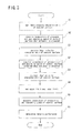
- FIG. 3 is a flowchart illustrating the damping test method according to this embodiment of the present invention.
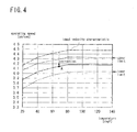
- FIG. 4 is a graph showing an example of an ideal velocity characteristic of a control surface set in this embodiment of the present invention, and specific examples of the processes shown in FIG. 3 .
- steps S1 to S6 are steps executed mainly by the control apparatus 40, whereas steps A1 and A2 are steps for which there is no limitation to the apparatus that mainly executes the steps.
- steps S1 to S6 are steps executed mainly by the control apparatus 40, whereas steps A1 and A2 are steps for which there is no limitation to the apparatus that mainly executes the steps.
- FIGS. 1 and 2 reference is made to FIGS. 1 and 2 as needed.
- the ideal velocity characteristic is set for each of the control surfaces of the aircraft 100 (see FIG.1 ) (step A1).
- the ideal velocity characteristic of the control surface is set by plotting the temperature of the pressure oil supplied to the actuator on the horizontal axis and plotting the operating speed of the control surface on the vertical axis.
- the ideal velocity characteristic set in step A1 is stored in the storage portion 42 of the control apparatus 40.
- Step A1 is executed for all the control surfaces that require the actuators of the aircraft 100 to have a damping function.
- Step A1 is executed by an apparatus that is different from the control apparatus 40, for example, a design computer.
- the ideal velocity characteristic of the control surface can be set by calculation based on the specifications of the aircraft 100 (see FIG. 1 ).
- the ideal velocity characteristic obtained by calculation may be corrected based on values obtained by testing.
- a test can be executed, for example, by creating a model simulating an actual control surface and attaching at least two actuators to the model, with one of the actuators placed in the damping mode and the rest of the actuators placed in the active mode. Then, the operating speed of the control surface is measured while changing the temperature of the pressure oil.
- step A2 After attaching the actuators to the control surface, one of the actuators is placed in the damping mode and the control surface is actuated with the rest of the actuators. At this time, the temperature of the pressure oil of the actuator in the damping mode and the operating speed of the control surface are measured (step A2). The temperature and the operating speed measured in step A2 are also stored in the storage portion 42 of the control apparatus 40. It is assumed that in step A2, the measurement of the pressure oil temperature and the operating speed is conducted using the displacement sensor 115 and the temperature sensor 116 (see FIG. 2 ). Furthermore, step A2 is executed for each of the actuators of the aircraft 100 that have the damping function.
- Step A2 may be executed by the control apparatus 40, or may be executed by an apparatus other than the control apparatus 40.
- the actuators are attached to the control surface, but the control apparatus 40 has not been mounted to the aircraft (or cannot be operated even if it is mounted) during production or overhaul of the aircraft. In this case, the operation of the actuators and the measurement of the temperature and the operating speed are conducted by an apparatus other than the control apparatus 40.
- test execution portion 41 accesses the storage portion 42. Then, the test execution portion 41 acquires, from the storage portion 42, the ideal velocity characteristic set in step A1 (step S1). Subsequently, the test execution portion 41 acquires, from the storage portion 42, the pressure oil temperature and the operating speed measured in step A2 when the actuator to be tested was in the damping mode (step S2).
- the test execution portion 41 corrects the ideal velocity characteristic of the control surface acquired in step S1 by using the pressure oil temperature and the control surface operating speed acquired in step S2 (step S3).
- the pressure oil temperature and the control surface operating speed acquired in step S2 define the point A in FIG. 4 .
- the test execution portion 41 translates the line representing the ideal velocity characteristic of the control surface in the direction of the longitudinal axis such that the line passes through the point A.
- step A2 a plurality of measurements are conducted for each of the actuators by varying the oil temperature, and a plurality of sets of data are stored in the storage portion 42 for each of the actuators.
- the test execution portion 41 calculates average values of the pressure oil temperature and the control surface operating speed from the plurality of sets of measured data, and translates the line representing the ideal velocity characteristic of the control surface such that the line passes through the point defined by the average values.
- test execution portion 41 sets an upper limit and a lower limit for the control surface operating speed according to the pressure oil temperature of the actuator to be tested by using the predicted value of the fluctuation range for a previously assumed fluctuation factor, with reference to the corrected ideal velocity characteristic (step S4).
- a pressure fluctuation due to a temperature change in the pressure oil in the actuator on the actuation side, a pressure fluctuation due to the supply path of the pressure oil supplied to the actuator on the actuation side, and a measurement error are assumed as the fluctuation factors.
- the predicted values of fluctuation ranges (%) for the fluctuation factors are C1 [%/100], C2 [%/100], and C3 [%/100], respectively.
- A represents the operating speed in the corrected ideal velocity characteristic (at any given temperature)
- ⁇ A represents difference the between the operating speed and each of the upper limit and the lower limit
- the upper limit (A+ ⁇ A) can be expressed by Equation 1 below and the lower limit (A- ⁇ A) can be represented by Equation 2 below.
- the test execution portion 41 calculates an upper limit and a lower limit on a temperature-by-temperature basis by using Equations 1 and 2 above. Thereby, as shown in FIG. 4 , an upper limit and a lower limit are set for the corrected ideal velocity characteristic. Note that specific values of C1, C2, and C3 can be determined from the past statistics.
- the test execution portion 41 actuates the control surface with the actuator on the actuation side in a state where the actuator to be tested is set in the damping mode, and measures the temperature of the pressure oil in the actuator to be tested and the operating speed of the control surface at this time (step S5).
- test execution portion 41 first causes the switching valve corresponding to the actuator to be tested to be operated via the actuator controller, and connects the pair of oil chambers of the actuator to be tested via the orifice. Then, the test execution portion 41 causes another actuator attached to the same control surface to be operated via the actuator controller, thereby actuating the control surface.
- an actuator not under test is driven by operating a preset hydraulic pump in the hydraulic line that supplies the pressure oil to that actuator.
- a preset hydraulic pump in the hydraulic line that supplies the pressure oil to that actuator.
- the hydraulic pump used is the same as the hydraulic pump used in step A2. With this configuration, it is possible to avoid adverse effects caused by variations in the generated pressure between different hydraulic pumps on the test result.
- step S5 it is preferable that the hydraulic line that supplies the pressure oil to the actuator to be operated does not supply the pressure oil to another actuator that receives a supply of the pressure oil from the hydraulic line, thus suspending the operation of the other actuator.
- the hydraulic line that supplies the pressure oil to the actuator to be operated does not supply the pressure oil to another actuator that receives a supply of the pressure oil from the hydraulic line, thus suspending the operation of the other actuator.
- suspending supply of the pressure oil to the other actuator in this way is also preferable in step A2.
- test execution portion 41 specifies the upper limit and lower limit corresponding to the pressure oil temperature measured in step S5 (see FIG. 4 ), and determines whether the operating speed measured in step S5 is between the specified upper limit and lower limit (step S6).
- step S6 determines that the actuator that has been tested passes the damping test.
- the test execution portion 41 determines that the actuator that has been tested fails the damping test.
- steps S1 to S6 completes the damping test for the actuator to be tested. I n this embodiment, steps S1 to S6 are executed for all the actuators of the aircraft 100 that have a damping function.
- the program according to this embodiment may be any program that causes a computer to execute steps S1 to S6 shown in FIG. 3 .
- the control apparatus 40 and the damping test method according to this embodiment can be implemented by installing the program in a computer and executing the program.
- An example of the computer is a so-called "flight controller", which is a computer mounted to an aircraft.
- the CPU Central Processing Unit
- the flight controller functions as the test execution portion 41 and executes the processes.
- a storage device such as a memory, included in the flight controller functions as the storage portion 42.
- the program according to this embodiment may be distributed in a state in which it is recorded in a computer readable recording medium, or may be distributed as data on the Internet.
- the recording medium include general-purpose semi conductor storage devices such as a CF (Compact Flash) and an SD (Secure Digital), magnetic recording mediums such as a Flexible Disk, and optical recording mediums such as a CD-ROM (Compact Disk Read Only Memory).
- CF Compact Flash
- SD Secure Digital
- magnetic recording mediums such as a Flexible Disk
- optical recording mediums such as a CD-ROM (Compact Disk Read Only Memory).
- the present invention it is possible to execute a damping test for an actuator attached to a control surface of an aircraft without using any pressure sensors, and also increase the reliability of a result of the damping test. Therefore, the present invention is useful for all aircrafts for which a damping test is required for an actuator. While the invention has been particularly shown and described with reference to exemplary embodiments thereof, the invention is not limited to these embodiments. It will be understood by those of ordinary skill in the art that various changes in form and details may be made therein without departing from the spirit and scope of the present invention as defined by the claims.
Landscapes
- Engineering & Computer Science (AREA)
- Aviation & Aerospace Engineering (AREA)
- Manufacturing & Machinery (AREA)
- Transportation (AREA)
- Physics & Mathematics (AREA)
- Fluid Mechanics (AREA)
- Automation & Control Theory (AREA)
- Testing Of Devices, Machine Parts, Or Other Structures Thereof (AREA)
- Fluid-Pressure Circuits (AREA)
Abstract
Description
- The present invention relates to a damping test method for executing a damping test for a hydraulically operated actuator for an aircraft, and a control apparatus, a hydraulic system, and a program for implementing the same.
- In general, an aircraft includes many moving surfaces (flight control surfaces). Among these, a primary flight control surface such as an aileron or an elevator is called a "control surface". Control surfaces are driven mainly by hydraulically operated actuators. Operating pressure oil is supplied to such actuators from an aircraft central hydraulic power source.
- In order to drive control surfaces, two actuators of different hydraulic lines are ordinarily used for a single control surface (for example, see JP 2003-40199A (
FIG.1 , FIGS. 10 to 14)). The reason for this is as follows: Even if one of the actuators stops functioning due to such reasons as a failure of the actuator itself or a loss or reduction in the function of the aircraft central hydraulic power source, the control surface can be driven by the other actuator of a different hydraulic line, thus preventing the aircraft from becoming unflyable. - However, when all the actuators attached to a control surface stop functioning due to a failure of the actuators or a failure of the controller, or a loss of the function of the hydraulic power source, the ability to hold the control surface still is lost, resulting in the generation of vibrations called "flutter". For this reason, the hydraulic line of each of the actuators is provided with a bypass line that connects two oil chambers provided in the actuator with each other by an orifice in the event of a function loss. When this bypass line is used, the actuator functions as a damper, thus suppressing the generation of flutter.
- Hereinafter, a state where the bypass line is used and each of the actuators serves as a damping device is referred to as a "damping mode". Conversely, a state where the bypass line is not used and each of the actuators is operated is referred to as an "active mode".
- Furthermore, in order for the actuators to reliably exert the damping function in the damping mode, a damping test is periodically executed in the aircraft. To execute this test, test pressure sensors are respectively disposed at ports of the oil chambers in each of the actuators. In the test, in a state where one of the actuators is placed in the damping mode, the control surfaces are first actuated at a constant speed with the other actuator, and signals from the pressure sensors are obtained at this time. Then, a damping force (for example, a pressure difference between the ports) of the actuator to be tested is calculated based on the obtained signals, and pass/fail is determined based on the calculated damping force.
- The above-described pressure sensors are used only in the damping test, and are never used in a normal operation of the aircraft. Therefore, from the viewpoint of realizing cost saving and a reduction in size and weight of hydraulic lines, a method of executing a damping test without using any pressure sensors has also been proposed. In the damping test method that does not involve the use of pressure sensors, the operating speed of the actuator on the damping side is measured at the time of actuating the control surfaces with the actuator on the actuation side in the active mode, and pass/fail is determined based on the measured result.
- However, in the case of the above-described damping test method that does not involve the use of pressure sensors, variations due to manufacturing tolerances of the actuators and the hydraulic lines, variations the effective working pressure in the actuator on the actuation side, measurement errors, and the like undesirably affect the measured results. Accordingly, the above-described damping test method that does not involve the use of pressure sensors has a problem in that it is difficult to provide a highly reliable result.
- On the other hand, it can be considered that the above-described problems may be solved by taking measures, including, for example, increasing the safety margin in the design of the actuators and the hydraulic lines. However, this inhibits the realization of cost savings and a reduction in size and weight, leading to a result similar to that obtained when pressure sensors are used.
- It is an exemplary object of the present invention to provide a damping test method, a control apparatus, a hydraulic system, and a program that can solve the above-described problems and increase the reliability of a result of a damping test without using any pressure sensors.
- A damping test method according to an exemplary aspect of the present invention for achieving the foregoing object is a damping test method for executing a damping test for a hydraulically operated actuator used for driving a control surface of an aircraft, the method including the steps of:
- (a) acquiring an ideal velocity characteristic of the control surface that is defined by a temperature of pressure oil supplied to the actuator and an operating speed of the control surface;
- (b) acquiring, in a state where at least two of the actuators are attached to the control surface and a pair of oil chambers of the actuator among the actuators that is to be tested by the damping test are connected with each other via an orifice, a temperature of the pressure oil of the actuator to be tested and an operating speed of the control surface when the actuator(s) not under test actuate(s) the control surface;
- (c) correcting the ideal velocity characteristic of the control surface acquired in step (a) by using the temperature of the pressure oil of the actuator to be tested and the operating speed of the control surface acquired in step (b);
- (d) setting an upper limit and a lower limit for the operating speed of the control surface according to the temperature of the pressure oil by using a predicted value for a fluctuation range for a fluctuation factor previously assumed as a factor of fluctuation of the operating speed of the control surface, with reference to the ideal velocity characteristic corrected in step (c);
- (e) measuring, after execution of steps (a) to (d), a temperature of the pressure oil of the actuator to be tested and an operating speed of the control surface by actuating the control surface with the actuator not under test in a state where the pair of oil chambers of the actuator to be tested are connected with each other via the orifice; and
- (f) determining whether the operating speed measured in step (e) falls within a range between the upper limit and the lower limit set in step (d) at the temperature of the pressure oil measured in step (e).
- According to the above-described feature, it is possible to eliminate the causes of reducing the reliability of a result obtained by a damping test conducted without using any pressure sensors, including, for example, variations due to manufacturing tolerances of the actuators and the hydraulic lines, variations in the effective working pressure of the actuator on the actuation side, and measurement errors. Therefore, according to the present invention, it is possible to increase the reliability of a result of a damping test without using any pressure sensors.
- According to a preferred aspect of the above-described damping test method of the present invention, in step (d), the previously assumed fluctuation factor includes a pressure fluctuation due to a temperature change in the pressure oil in the actuator not under test, a pressure fluctuation due to a flow path resistance in a supply path of the pressure oil supplied to the actuator not under test, a measurement error in measuring a temperature of the pressure oil of the actuator to be tested, and a measurement error in measuring an operating speed of the control surface. According to this aspect, it is possible to more reliably minimize the causes of reducing the reliability of the result.
- In the above-described damping test method of the present invention, it is preferable that, in step (c), the ideal velocity characteristic is corrected such that a line representing the ideal velocity characteristic of the control surface passes through a point defined by the temperature of the pressure oil of the actuator to be tested and the operating speed of the control surface. In this case, variations due to manufacturing tolerances of the actuators and the hydraulic lines can be reliably corrected.
- Furthermore, in the above-described damping test method according to the present invention, it is preferable that, when the aircraft includes a plurality of hydraulic lines for supplying pressure oil to the actuators, in step (b) and step (e), the actuator not under test is driven by operating only a preset hydraulic pump in the hydraulic line that supplies the pressure oil to the actuator and suspending the operation of another actuator or actuators receiving a supply of the pressure oil from that hydraulic line. In this case, it is possible to avoid adverse effects on a testing result due to variations between the pressures generated by different hydraulic pumps and variations in the pressure supplied from the hydraulic lines.
- A program according to an exemplary aspect of the present invention for achieving the foregoing object is a program for executing, by a computer, a damping test for a hydraulically operated actuator used for driving a control surface of an aircraft, the program causes the computer to execute the steps of:
- (a) acquiring an ideal velocity characteristic of the control surface that is defined by a temperature of pressure oil supplied to the actuator and an operating speed of the control surface;
- (b) acquiring, in a state where at least two of the actuators are attached to the control surface and a pair of oil chambers of the actuator among the actuators that is to be tested by the damping test are connected with each other via an orifice, a temperature of the pressure oil of the actuator to be tested and an operating speed of the control surface when the actuator(s) not under test actuate(s) the control surface;
- (c) correcting the ideal velocity characteristic of the control surface acquired in step (a) by using the temperature of the pressure oil of the actuator to be tested and the operating speed of the control surface acquired in step (b);
- (d) setting an upper limit and a lower limit for the operating speed of the control surface according to the temperature of the pressure oil by using a predicted value for a fluctuation range for a fluctuation factor previously assumed as a factor of fluctuation of the operating speed of the control surface, with reference to the ideal velocity characteristic corrected in step (c);
- (e) measuring, after execution of steps (a) to (d), a temperature of the pressure oil of the actuator to be tested and an operating speed of the control surface by actuating the control surface with the actuator not under test in a state where the pair of oil chambers of the actuator to be tested are connected with each other via the orifice; and
- (f) determining whether the operating speed measured in step (e) falls within a range between the upper limit and the lower limit set in step (d) at the temperature of the pressure oil measured in step (e).
- According to a preferred aspect of the above-described program of the present invention, in step (d), the previously assumed fluctuation factor includes a pressure fluctuation due to a temperature change in the pressure oil in the actuator not under test, a pressure fluctuation due to a flow path resistance in a supply path of the pressure oil supplied to the actuator not under test, a measurement error in measuring a temperature of the pressure oil of the actuator to be tested, and a measurement error in measuring an operating speed of the control surface.
- In the above-described program of the present invention, it is preferable that, in step (c), the ideal velocity characteristic is corrected such that a line representing the ideal velocity characteristic of the control surface passes through a point defined by the temperature of the pressure oil of the actuator to be tested and the operating speed of the control surface.
- Furthermore, in the above-described program of the present invention, it is preferable that when the aircraft includes a plurality of hydraulic lines for supplying pressure oil to the actuators,
in step (b) and step (e), the actuator not under test is driven by operating only a preset hydraulic pump in the hydraulic line that supplies the pressure oil to the actuator and suspending the operation of another actuator or actuators receiving a supply of the pressure oil from that hydraulic line. - Furthermore, in order to achieve the foregoing object, a control apparatus according to an exemplary aspect of the present invention is a control apparatus that controls at least two hydraulically operated actuators attached to a control surface of an aircraft, the apparatus including:
- a test execution portion that executes a damping test for each of the at least two actuators,
- wherein the test execution portion acquires an ideal velocity characteristic of the control surface that is defined by a temperature of pressure oil supplied to the actuator and an operating speed of the control surface;
- acquires, in a state where the at least two actuators are attached to the control surface and a pair of oil chambers of the actuator among the actuators that is to be tested by the damping test are connected with each other via an orifice, a temperature of the pressure oil of the actuator to be tested and an operating speed of the control surface when the actuator(s) not under test actuate(s) the control surface;
- corrects the acquired ideal velocity characteristic of the control surface by using the temperature of the pressure oil of the actuator to be tested and the operating speed of the control surface that have been acquired;
- sets an upper limit and a lower limit for the operating speed of the control surface according to the temperature of the pressure oil by using a predicted value for a fluctuation range for a fluctuation factor previously assumed as a factor of fluctuation of the operating speed of the control surface, with reference to the corrected ideal velocity characteristic;
- measures a temperature of the pressure oil of the actuator to be tested and an operating speed of the control surface by actuating the control surface with the actuator not under test in a state where the pair of oil chambers of the actuator to be tested are connected with each other via the orifice; and
- determines whether the measured operating speed falls within a range between the upper limit and the lower limit at the measured temperature of the pressure oil.
- Additionally, a hydraulic system according to an exemplary aspect of the present invention for achieving the foregoing object is a hydraulic system used for driving a control surface of an aircraft, the system including:
- at least two hydraulically operated actuators attached to the control surface; and
- a control apparatus that controls each of the at least two actuators and executes a damping test for each of the actuators,
- wherein the control apparatus acquires an ideal velocity characteristic of the control surface that is defined by a temperature of pressure oil supplied to the actuator and an operating speed of the control surface;
- acquires, in a state where the at least two actuators are attached to the control surface and a pair of oil chambers of the actuator among the actuators that is to be tested by the damping test are connected with each other via an orifice, a temperature of the pressure oil of the actuator to be tested and an operating speed of the control surface when the actuator(s) not under test actuate(s) the control surface;
- corrects the acquired ideal velocity characteristic of the control surface by using the temperature of the pressure oil of the actuator to be tested and the operating speed of the control surface that have been acquired;
- sets an upper limit and a lower limit for the operating speed of the control surface according to the temperature of the pressure oil by using a predicted value for a fluctuation range for a fluctuation factor previously assumed as a factor of fluctuation of the operating speed of the control surface, with reference to the corrected ideal velocity characteristic;
- measures a temperature of the pressure oil of the actuator to be tested and an operating speed of the control surface by actuating the control surface with the actuator not under test in a state where the pair of oil chambers of the actuator to be tested are connected with each other via the orifice; and
- determines whether the measured operating speed falls within a range between the upper limit and the lower limit at the measured temperature of the pressure oil.
- As described above, according to the present invention, it is possible to increase the reliability of a result of a damping test without using any pressure sensors.
-
-
FIG. 1 is a diagram showing a state where a hydraulic system according to an embodiment of the present invention is mounted to an aircraft. -
FIG. 2 is a configuration diagram schematically showing the configuration of a control apparatus and a hydraulic system according to an embodiment of the present invention. -
FIG. 3 is a flowchart illustrating a damping test method according to an embodiment of the present invention. -
FIG. 4 is a graph showing an example of the ideal velocity characteristic for a control surface set in an embodiment of the present invention and specific examples of the processes shown inFIG. 3 . - Hereinafter, a damping test method, a control apparatus, a hydraulic system, and a program according to an embodiment of the present invention will be described with reference to
FIGS. 1 to 4 . First, the hydraulic system of this embodiment and an aircraft on which the hydraulic system is mounted will be described with reference toFIG.1. FIG. 1 is a diagram showing a state where the hydraulic system of an embodiment of the present invention is mounted to an aircraft. - In
FIG. 1 , a rear end portion of afuselage 101 of anaircraft 100 andtailplanes aircraft 100 is omitted. As shown inFIG. 1 , thetailplane 102 is provided with anelevator 104 as a moving surface constituting a control surface. Likewise, thetailplane 103 is provided with anelevator 105 as a moving surface constituting a control surface. - As shown in
FIG.1 , at least two hydraulically operated actuators are attached to each of theelevators elevators FIG.1 , twoactuators elevator 104. Likewise, twoactuators elevator 105. - The
actuators hydraulic system 30 of this embodiment. In addition to these actuators, thehydraulic system 30 further includeshydraulic lines FIG. 2 , not shown inFIG.1 ). - The
hydraulic line 10 is used for supplying pressure oil to theactuator 11 attached to theleft tail plane 102 and theactuator 21 attached to theright tailplane 103. Thehydraulic line 10 includes ahydraulic circuit 13 connected with theactuator pump unit 14 serving as a hydraulic power source. - On the other hand, the
hydraulic line 20 is used for supplying pressure oil to theactuator 12 attached to theleft tailplane 102 and theactuator 22 attached to theright tailplane 103. Thehydraulic line 20 includes ahydraulic circuit 23 connected with theactuators pump unit 24 serving as a hydraulic power source. - In the
hydraulic line 10, thepump unit 14 includes an engine drivenhydraulic pump 15 that is driven by the aircraft engine and an electric motor drivenhydraulic pump 16 that is driven by an electric motor. Likewise, in thehydraulic line 20, thepump unit 24 includes an engine drivenhydraulic pump 25 that is driven by the aircraft engine and an electric motor drivenhydraulic pump 26 that is driven by an electric motor. In addition, as shown inFIG. 2 described below, thepump unit 14 includes atemperature sensor 116 for measuring the temperature of the pressure oil that is to be supplied. Thepump unit 24 also includes asimilar temperature sensor 126. - Note that the engine driven hydraulic pump is indicated as "P1" and the electric motor driven hydraulic pump is indicated as "P2" in
FIG. 1 . In general, in an aircraft, the engine driven hydraulic pump is constantly operated, whereas the electric motor driven hydraulic pump is operated as needed. - Next, the configuration of the control apparatus and the hydraulic system according to this embodiment will be described with reference to
FIG. 2. FIG. 2 is a configuration diagram schematically showing the configuration of the control apparatus and the hydraulic system according to an embodiment of the present invention. Note that only theactuators FIG.1 are shown inFIG. 2 . Although theactuators FIG. 2 , the configuration and the form of connection of these actuators are the same as those of theactuators - As shown in
FIG. 2 , thehydraulic system 30 includes acontrol apparatus 40, in addition to theactuators 11 and 12 (theactuators hydraulic lines FIG.1 . Thehydraulic system 30 further includes anactuator controller 50. - The
actuator 11 includes acylindrical casing 110, apiston 112 that reciprocates inside thecasing 110, and apiston rod 111 that is operated in response to thepiston 112. The interior of thecasing 110 is divided into two spaces by thepiston 112, and these two spaces serve as a pair ofoil chambers - When pressure oil is supplied from the
pump unit 14 to one of theoil chambers hydraulic circuit 13 and the pressure oil is then discharged from the other of theoil chambers piston 112 and thepiston rod 111 move, as a result of which theelevator 104 is actuated. Further, theactuator 11 is provided with adisplacement sensor 115 for measuring the amount of movement of thepiston 112. - Like the
actuator 11, theactuator 12 includes acasing 120, apiston 122, and apiston rod 121. Furthermore, theactuator 12 is also provided with adisplacement sensor 125. Note that the configuration and the function of theactuator 12 are the same as those of theactuator 11, and therefore a further description of theactuator 12 is omitted. - As described with reference to
FIG.1 , thehydraulic line 10 includes thepump unit 14 and thehydraulic circuit 13. Thehydraulic circuit 13 is provided with acontrol valve 17. For example, thecontrol valve 17 adjusts the amount of pressure oil supplied to theactuator 11 and switches between the oil chambers to which pressure oil is to be supplied, in accordance with a command from theactuator controller 50, which will be described below. - The
hydraulic circuit 13 is provided with abypass line 18 that can connect theoil chamber 113 and theoil chamber 114 of theactuator 11 directly with each other. Furthermore, a switchingvalve 19 is provided on thebypass line 18. The switchingvalve 19 can be switched between a state where thebypass line 18 is interrupted (interrupted state) and a state where theoil chamber 113 and theoil chamber 114 are connected with each other via anorifice 19a (connected state). - When there is no abnormality in the
hydraulic line 10, the switchingvalve 19 switches thebypass line 18 to the interrupted state in accordance with a command from theactuator controller 50. Consequently, theactuator 11 is placed in the active mode. On the other hand, when theactuator 11 stops functioning due to a failure of itself or a failure of thecontroller 50 or some abnormality in thehydraulic line 10, the switchingvalve 19 switches thebypass line 18 to the connected state in accordance with a command from theactuator controller 50. Consequently, theactuator 11 is placed in the damping mode, in which it functions as a damping device. - As described with reference to
FIG. 1 , thehydraulic line 20 includes thepump unit 24 and thehydraulic circuit 23. Thehydraulic circuit 23 is provided with acontrol valve 27. Furthermore, thehydraulic circuit 23 is provided with abypass line 28 that can connect theoil chamber 123 and theoil chamber 124 of theactuator 12 directly with each other. A switchingvalve 29 is provided on thebypass line 28. Thecontrol valve 27 and the switchingvalve 29 are operated in accordance with a command from anactuator controller 51. - The
control valve 27, thebypass line 28, and the switchingvalve 29 provided in thehydraulic line 20 are configured and function in the same manner as thecontrol valve 17, thebypass line 18, and the switchingvalve 19, respectively, provided in thehydraulic line 10. Note that the configuration and the function of thehydraulic line 20 are the same as those of thehydraulic line 10 as mentioned above, and therefore a further description of thehydraulic line 20 is omitted. - The
control apparatus 40 controls the actuators via theactuator controllers FIG. 1 ). In this embodiment, thecontrol apparatus 40 is a computer called a "flight controller" mounted to theaircraft 100. - The
actuator controller 50 generates control signals for operating thecontrol valve 17 and the switchingvalve 19 in accordance with a command from thecontrol apparatus 40, and outputs the control signals to thecontrol valve 17 and the switchingvalve 19. Likewise, theactuator controller 51 generates control signals for operating thecontrol valve 27 and the switchingvalve 29 in accordance with a command from thecontrol apparatus 40, and outputs the control signals to thecontrol valve 27 and the switchingvalve 29. - The
control apparatus 40 includes atest execution portion 41 that executes a damping test for the actuators and astorage portion 42 storing the information necessary for the damping test. In this embodiment, thetest execution portion 41 sequentially selects at least two actuators attached to the same control surface as a test subject and executes a damping test on the test subjects. - Furthermore, the
test execution portion 41 executes the damping tests without using any pressure sensors for measuring the pressure of the oil chambers of the actuators. At this time, thetest execution portion 41 executes the following processes in order to suppress adverse effects on test results, caused by, for example, variations due to manufacturing tolerances of the actuators and the hydraulic lines, variations in the effective working pressure of the actuator on the actuation side, which is not under test, and measurement errors. - Specifically, the
test execution portion 41 first acquires the ideal velocity characteristic of a control surface. The ideal velocity characteristic of a control surface is defined by the temperature of the pressure oil supplied to an actuator and the operating speed of the control surface. In this embodiment, the ideal velocity characteristic of the control surface is previously stored in thestorage portion 42. Note that specific examples of the ideal velocity characteristic of the control surface will be described below with reference toFIG. 4 . - In this embodiment, "operating speed of a control surface" means, for example, the operating speed of an actuator in the active mode, which drives the control surface, or in other words, the movement speed of the piston of the actuator in the active mode. Furthermore, when some of the at least two actuators attached to the same control surface are in the active mode and the rest are in the damping mode, the "operating speed of an actuator" may be the operating speed of the actuators in the active mode or may be the average value of the operating speed of the actuators in the active mode and the operating speed of the actuators in the damping mode.
- Subsequently, the
test execution portion 41 acquires the temperature of pressure oil of the actuator to be tested and the operating speed of the control surface when the actuator is attached to the control surface, for example, during production or overhaul of the aircraft. - Specifically, in a state where at least two actuators have been previously attached to the control surface and those of the actuators that are to be tested are placed in the damping mode, the control surface is actuated with the other actuators. Then, the temperature of the pressure oil of the actuator in the damping mode and the operating speed of the control surface are measured. The measurement is carried out on an actuator-by-actuator basis by setting each of the actuators in the damping mode. The measured values are stored in the
storage portion 42. Thereafter, thetest execution portion 41 acquires, from thestorage portion 42, the temperature of the pressure oil and the operating speed of the control surface that were measured when the actuators that are to be tested were in the damping mode. - For example, when the
actuators actuators actuators elevator 104, for example, during production or overhaul of the aircraft, are sequentially measured. When theactuator 11 is tested, thetest execution portion 41 acquires the pressure oil temperature of theactuator 11 and the operating speed of the control surface measured when theactuator 11 was in the damping mode. - After acquiring the ideal velocity characteristic of the control surface and the measured values obtained during production or the like described above, the
test execution portion 41 corrects the ideal velocity characteristic of the control surface by using the measurement values obtained during production or the like. This correction provides an ideal velocity characteristic for which variations due to manufacturing tolerances of the actuators and the hydraulic lines, including, for example, variations in the performance of the control valve and variations in the performance of the orifice have been taken into consideration. Therefore, adverse effect of these variations on test results can be avoided. Note that a specific correction process will be described below with reference toFIG. 4 . - Subsequently, upon completion of the correction, the
test execution portion 41 sets an upper limit and a lower limit for the operating speed of the control surface according to the temperature of pressure oil of the actuator to be tested, with reference to the corrected ideal velocity characteristic. At this time, thetest execution portion 41 performs the setting by using a predicted value for the fluctuation range for a fluctuation factor previously assumed as a factor of fluctuation of the operating speed of the control surface. In this embodiment, the predicted value for the fluctuation range is stored in thestorage portion 42. - Examples of the fluctuation factor include a pressure fluctuation due to a temperature change in the pressure oil of the actuator on the actuation side, which is not under test, and similarly a pressure fluctuation (for example, filter clogging) caused by the flow path resistance in the supply path of the pressure oil supplied to the actuator on the actuation side. Further examples of the fluctuation factor include various measurement errors such as a measurement error in measuring the temperature of the pressure oil of the actuator to be tested and a measurement error in measuring the operating speed of the control surface. The fluctuation range for each fluctuation factor can be determined from the past statistics. Specific examples of the upper limit and the lower limit will be described below with reference to
FIG. 4 . - Subsequently, the
test execution portion 41 actuates the control surface with the actuator on the actuation side in a state where the actuator to be tested is set in the damping mode, and measures the temperature of the pressure oil of the actuator to be tested and the operating speed of the control surface at this time. In this embodiment, it is assumed that thetest execution portion 41 measures the pressure oil temperature and the operating speed based on signals from thedisplacement sensor 115 and thetemperature sensor 116. - Thereafter, the
test execution portion 41 determines whether the measured operating speed falls within the range between the upper limit and the lower limit at the measured pressure oil temperature. If it falls within the range, thetest execution portion 41 determines that the actuator that has been tested passes the damping test. If it does not fall within the range, on the other hand, thetest execution portion 41 determines that the actuator that has been tested fails the damping test. - In this way, the determination whether the damping test is passed or failed is performed based on the previously set upper limit and lower limit. Since the upper limit and the lower limit are set taking into consideration a fluctuation factor that causes a fluctuation of the operating speed of the control surface, adverse effects due to variations in the effective working pressure of the actuator on the actuation side, measurement errors, and the like on test results can be suppressed.
- Next, a damping test method according to this embodiment will be described with reference to
FIGS. 3 and4 .FIG. 3 is a flowchart illustrating the damping test method according to this embodiment of the present invention.FIG. 4 is a graph showing an example of an ideal velocity characteristic of a control surface set in this embodiment of the present invention, and specific examples of the processes shown inFIG. 3 . - In
FIG. 3 , steps S1 to S6 are steps executed mainly by thecontrol apparatus 40, whereas steps A1 and A2 are steps for which there is no limitation to the apparatus that mainly executes the steps. In the following description, reference is made toFIGS. 1 and2 as needed. - First, as shown in
FIG. 3 , the ideal velocity characteristic is set for each of the control surfaces of the aircraft 100 (seeFIG.1 ) (step A1). In the example shown inFIG. 4 , the ideal velocity characteristic of the control surface is set by plotting the temperature of the pressure oil supplied to the actuator on the horizontal axis and plotting the operating speed of the control surface on the vertical axis. The ideal velocity characteristic set in step A1 is stored in thestorage portion 42 of thecontrol apparatus 40. Step A1 is executed for all the control surfaces that require the actuators of theaircraft 100 to have a damping function. - Step A1 is executed by an apparatus that is different from the
control apparatus 40, for example, a design computer. The ideal velocity characteristic of the control surface can be set by calculation based on the specifications of the aircraft 100 (seeFIG. 1 ). In addition, the ideal velocity characteristic obtained by calculation may be corrected based on values obtained by testing. - In this case, a test can be executed, for example, by creating a model simulating an actual control surface and attaching at least two actuators to the model, with one of the actuators placed in the damping mode and the rest of the actuators placed in the active mode. Then, the operating speed of the control surface is measured while changing the temperature of the pressure oil.
- Next, after attaching the actuators to the control surface, one of the actuators is placed in the damping mode and the control surface is actuated with the rest of the actuators. At this time, the temperature of the pressure oil of the actuator in the damping mode and the operating speed of the control surface are measured (step A2). The temperature and the operating speed measured in step A2 are also stored in the
storage portion 42 of thecontrol apparatus 40. It is assumed that in step A2, the measurement of the pressure oil temperature and the operating speed is conducted using thedisplacement sensor 115 and the temperature sensor 116 (seeFIG. 2 ). Furthermore, step A2 is executed for each of the actuators of theaircraft 100 that have the damping function. - Step A2 may be executed by the
control apparatus 40, or may be executed by an apparatus other than thecontrol apparatus 40. For example, a case is conceivable where the actuators are attached to the control surface, but thecontrol apparatus 40 has not been mounted to the aircraft (or cannot be operated even if it is mounted) during production or overhaul of the aircraft. In this case, the operation of the actuators and the measurement of the temperature and the operating speed are conducted by an apparatus other than thecontrol apparatus 40. - Next, the
test execution portion 41 accesses thestorage portion 42. Then, thetest execution portion 41 acquires, from thestorage portion 42, the ideal velocity characteristic set in step A1 (step S1). Subsequently, thetest execution portion 41 acquires, from thestorage portion 42, the pressure oil temperature and the operating speed measured in step A2 when the actuator to be tested was in the damping mode (step S2). - Next, the
test execution portion 41 corrects the ideal velocity characteristic of the control surface acquired in step S1 by using the pressure oil temperature and the control surface operating speed acquired in step S2 (step S3). For example, it is assumed that the pressure oil temperature and the control surface operating speed acquired in step S2 define the point A inFIG. 4 . In this case, as shown inFIG. 4 , thetest execution portion 41 translates the line representing the ideal velocity characteristic of the control surface in the direction of the longitudinal axis such that the line passes through the point A. - Although the correction is made based only on a single set of measurement data in step S3, this embodiment is not limited thereto. For example, it is assumed that, in step A2, a plurality of measurements are conducted for each of the actuators by varying the oil temperature, and a plurality of sets of data are stored in the
storage portion 42 for each of the actuators. In this case, for example, thetest execution portion 41 calculates average values of the pressure oil temperature and the control surface operating speed from the plurality of sets of measured data, and translates the line representing the ideal velocity characteristic of the control surface such that the line passes through the point defined by the average values. - Next, the
test execution portion 41 sets an upper limit and a lower limit for the control surface operating speed according to the pressure oil temperature of the actuator to be tested by using the predicted value of the fluctuation range for a previously assumed fluctuation factor, with reference to the corrected ideal velocity characteristic (step S4). - For example, a pressure fluctuation due to a temperature change in the pressure oil in the actuator on the actuation side, a pressure fluctuation due to the supply path of the pressure oil supplied to the actuator on the actuation side, and a measurement error are assumed as the fluctuation factors. Also, the predicted values of fluctuation ranges (%) for the fluctuation factors are C1 [%/100], C2 [%/100], and C3 [%/100], respectively. In this case, where A represents the operating speed in the corrected ideal velocity characteristic (at any given temperature) and ΔA represents difference the between the operating speed and each of the upper limit and the lower limit, the upper limit (A+ΔA) can be expressed by
Equation 1 below and the lower limit (A-ΔA) can be represented byEquation 2 below. -

-

- The
test execution portion 41 calculates an upper limit and a lower limit on a temperature-by-temperature basis by usingEquations FIG. 4 , an upper limit and a lower limit are set for the corrected ideal velocity characteristic. Note that specific values of C1, C2, and C3 can be determined from the past statistics. - Next, after the upper limit and the lower limit are set, the
test execution portion 41 actuates the control surface with the actuator on the actuation side in a state where the actuator to be tested is set in the damping mode, and measures the temperature of the pressure oil in the actuator to be tested and the operating speed of the control surface at this time (step S5). - Specifically, the
test execution portion 41 first causes the switching valve corresponding to the actuator to be tested to be operated via the actuator controller, and connects the pair of oil chambers of the actuator to be tested via the orifice. Then, thetest execution portion 41 causes another actuator attached to the same control surface to be operated via the actuator controller, thereby actuating the control surface. - At this time, in this embodiment, it is preferable that an actuator not under test is driven by operating a preset hydraulic pump in the hydraulic line that supplies the pressure oil to that actuator. For example, when a single hydraulic line is provided with an engine driven hydraulic pump and an electric motor driven hydraulic pump (see
FIG.1 ), it is preferable to use one of the hydraulic pumps. In this case, it is particularly preferable that the hydraulic pump used is the same as the hydraulic pump used in step A2. With this configuration, it is possible to avoid adverse effects caused by variations in the generated pressure between different hydraulic pumps on the test result. - Furthermore, at the time of execution of step S5, it is preferable that the hydraulic line that supplies the pressure oil to the actuator to be operated does not supply the pressure oil to another actuator that receives a supply of the pressure oil from the hydraulic line, thus suspending the operation of the other actuator. With this configuration, it is possible to avoid adverse effects on the test result caused by variations in the pressures supplied from the hydraulic line. Note that suspending supply of the pressure oil to the other actuator in this way is also preferable in step A2.
- Thereafter, the
test execution portion 41 specifies the upper limit and lower limit corresponding to the pressure oil temperature measured in step S5 (seeFIG. 4 ), and determines whether the operating speed measured in step S5 is between the specified upper limit and lower limit (step S6). - If the result of the determination performed in step S6 indicates that the measured operating speed is between the upper limit and the lower limit, the
test execution portion 41 determines that the actuator that has been tested passes the damping test. On the other hand, if the result of the determination performed in step S6 indicates that the measured operating speed is not between the upper limit and the lower limit, thetest execution portion 41 determines that the actuator that has been tested fails the damping test. - Execution of steps S1 to S6 completes the damping test for the actuator to be tested. I n this embodiment, steps S1 to S6 are executed for all the actuators of the
aircraft 100 that have a damping function. - As described above, in this embodiment, factors of reducing the reliability of a damping test performed without using any pressure sensors can be eliminated. Therefore, according to this embodiment, it is possible to increase the reliability of a result of a damping test without using any pressure sensors. Consequently, it is also possible to facilitate cost saving and a reduction in size and weight of an aircraft hydraulic system.
- The program according to this embodiment may be any program that causes a computer to execute steps S1 to S6 shown in
FIG. 3 . Thecontrol apparatus 40 and the damping test method according to this embodiment can be implemented by installing the program in a computer and executing the program. - An example of the computer is a so-called "flight controller", which is a computer mounted to an aircraft. In this case, the CPU (Central Processing Unit) of the flight controller functions as the
test execution portion 41 and executes the processes. Further, a storage device, such as a memory, included in the flight controller functions as thestorage portion 42. Note that the program according to this embodiment may be distributed in a state in which it is recorded in a computer readable recording medium, or may be distributed as data on the Internet. - Specific examples of the recording medium include general-purpose semi conductor storage devices such as a CF (Compact Flash) and an SD (Secure Digital), magnetic recording mediums such as a Flexible Disk, and optical recording mediums such as a CD-ROM (Compact Disk Read Only Memory).
- As described above, according to the present invention, it is possible to execute a damping test for an actuator attached to a control surface of an aircraft without using any pressure sensors, and also increase the reliability of a result of the damping test. Therefore, the present invention is useful for all aircrafts for which a damping test is required for an actuator.
While the invention has been particularly shown and described with reference to exemplary embodiments thereof, the invention is not limited to these embodiments. It will be understood by those of ordinary skill in the art that various changes in form and details may be made therein without departing from the spirit and scope of the present invention as defined by the claims.
Claims (10)
- A damping test method for executing a damping test for a hydraulically operated actuator used for driving a control surface of an aircraft, the method comprising the steps of:(a) acquiring an ideal velocity characteristic of the control surface that is defined by a temperature of pressure oil supplied to the actuator and an operating speed of the control surface;(b) acquiring, in a state where at least two of the actuators are attached to the control surface and a pair of oil chambers of the actuator among the actuators that is to be tested by the damping test are connected with each other via an orifice, a temperature of the pressure oil of the actuator to be tested and an operating speed of the control surface when the actuator(s) not under test actuate(s) the control surface;(c) correcting the ideal velocity characteristic of the control surface acquired in step (a) by using the temperature of the pressure oil of the actuator to be tested and the operating speed of the control surface acquired in step (b);(d) setting an upper limit and a lower limit for the operating speed of the control surface according to the temperature of the pressure oil by using a predicted value for a fluctuation range for a fluctuation factor previously assumed as a factor of fluctuation of the operating speed of the control surface, with reference to the ideal velocity characteristic corrected in step (c);(e) measuring, after execution of steps (a) to (d), a temperature of the pressure oil of the actuator to be tested and an operating speed of the control surface by actuating the control surface with the actuator not under test in a state where the pair of oil chambers of the actuator to be tested are connected with each other via the orifice; and(f) determining whether the operating speed measured in step (e) falls within a range between the upper limit and the lower limit set in step (d) at the temperature of the pressure oil measured in step (e).
- The damping test method according to claim 1,
wherein, in step (d), the previously assumed fluctuation factor comprises a pressure fluctuation due to a temperature change in the pressure oil in the actuator not under test, a pressure fluctuation due to a flow path resistance in a supply path of the pressure oil supplied to the actuator not under test, a measurement error in measuring a temperature of the pressure oil of the actuator to be tested, and a measurement error in measuring an operating speed of the control surface. - The damping test method according to claim 1 or 2,
wherein, in step (c), the ideal velocity characteristic is corrected such that a line representing the ideal velocity characteristic of the control surface passes through a point defined by the temperature of the pressure oil of the actuator to be tested and the operating speed of the control surface. - The damping test method according to any of claims 1 to 3,
wherein the aircraft comprises a plurality of hydraulic lines for supplying pressure oil to the actuators, and,
in step (b) and step (e), the actuator not under test is driven by operating only a preset hydraulic pump in the hydraulic line that supplies the pressure oil to the actuator and suspending the operation of another actuator or actuators receiving a supply of the pressure oil from that hydraulic line. - A program for executing, by a computer, a damping test for a hydraulically operated actuator used for driving a control surface of an aircraft, the program causes the computer to execute the steps of:(a) acquiring an ideal velocity characteristic of the control surface that is defined by a temperature of pressure oil supplied to the actuator and an operating speed of the control surface;(b) acquiring, in a state where at least two of the actuators are attached to the control surface and a pair of oil chambers of the actuator among the actuators that is to be tested by the damping test are connected with each other via an orifice, a temperature of the pressure oil of the actuator to be tested and an operating speed of the control surface when the actuator(s) not under test actuate(s) the control surface;(c) correcting the ideal velocity characteristic of the control surface acquired in step (a) by using the temperature of the pressure oil of the actuator to be tested and the operating speed of the control surface acquired in step (b);(d) setting an upper limit and a lower limit for the operating speed of the control surface according to the temperature of the pressure oil by using a predicted value for a fluctuation range for a fluctuation factor previously assumed as a factor of fluctuation of the operating speed of the control surface, with reference to the ideal velocity characteristic corrected in step (c);(e) measuring, after execution of steps (a) to (d), a temperature of the pressure oil of the actuator to be tested and an operating speed of the control surface by actuating the control surface with the actuator not under test in a state where the pair of oil chambers of the actuator to be tested are connected with each other via the orifice; and(f) determining whether the operating speed measured in step (e) falls within a range between the upper limit and the lower limit set in step (d) at the temperature of the pressure oil measured in step (e).
- The program according to claim 5,
wherein, in step (d), the previously assumed fluctuation factor comprises a pressure fluctuation due to a temperature change in the pressure oil in the actuator not under test, a pressure fluctuation due to a flow path resistance in a supply path of the pressure oil supplied to the actuator not under test, a measurement error in measuring a temperature of the pressure oil of the actuator to be tested, and a measurement error in measuring an operating speed of the control surface. - The program according to claim 5 or 6,
wherein, in step (c), the ideal velocity characteristic is corrected such that a line representing the ideal velocity characteristic of the control surface passes through a point defined by the temperature of the pressure oil of the actuator to be tested and the operating speed of the control surface. - The program according to any of claims 5 to 7,
wherein the aircraft comprises a plurality of hydraulic lines for supplying pressure oil to the actuators, and,
in step (b) and step (e), the actuator not under test is driven by operating only a preset hydraulic pump in the hydraulic line that supplies the pressure oil to the actuator and suspending the operation of another actuator or actuators receiving a supply of the pressure oil from that hydraulic line. - A control apparatus(40) that controls at least two hydraulically operated actuators(11,12) attached to a control surface(104) of an aircraft, the apparatus comprising:a test execution portion(41) that executes a damping test for each of the at least two actuators(11,12),wherein the test execution portion(41) acquires an ideal velocity characteristic of the control surface(104) that is defined by a temperature of pressure oil supplied to the actuator and an operating speed of the control surface(104);acquires, in a state where the at least two actuators(11,12) are attached to the control surface(104) and a pair of oil chambers(113,114) of the actuator(11) among the actuators(11,12) that is to be tested by the damping test are connected with each other via an orifice(19a), a temperature of the pressure oil of the actuator(11) to be tested and an operating speed of the control surface(104) when the actuator(12) not under test actuate the control surface(104);corrects the acquired ideal velocity characteristic of the control surface(104) by using the temperature of the pressure oil of the actuator(11) to be tested and the operating speed of the control surfaces(104) that have been acquired;sets an upper limit and a lower limit for the operating speed of the control surface(104) according to the temperature of the pressure oil by using a predicted value for a fluctuation range for a fluctuation factor previously assumed as a factor of fluctuation of the operating speed of the control surface(104), with reference to the corrected ideal velocity characteristic;measures a temperature of the pressure oil of the actuator(11) to be tested and an operating speed of the control surfaces(104) by actuating the control surface(104) with the actuator(12) not under test in a state where the pair of oil chambers(113,114) of the actuator(11) to be tested are connected with each other via the orifice(19a); anddetermines whether the measured operating speed falls within a range between the upper limit and the lower limit at the measured temperature of the pressure oil.
- A hydraulic system(30) used for driving a control surface(104) of an aircraft, the system comprising:at least two hydraulically operated actuators(11,12) attached to the control surface(104); anda control apparatus(40) that controls each of the at least two actuators(11,12) and executes a damping test for each of the actuators(11,12),wherein the control apparatus(40) acquires an ideal velocity characteristic of the control surfaces(104) that is defined by a temperature of pressure oil supplied to the actuator and an operating speed of the control surface(104);acquires, in a state where the at least two actuators(11,12) are attached to the control surface(104) and a pair of oil chambers(113,114) of the actuator(11) among the actuators(11,12) that is to be tested by the damping test are connected with each other via an orifice(19a), a temperature of the pressure oil of the actuator(11)to be tested and an operating speed of the control surface(104) when the actuator(12) not under test actuate(s) the control surface(104);corrects the acquired ideal velocity characteristic of the control surfaces(104) by using the temperature of the pressure oil of the actuator(11) to be tested and the operating speed of the control surface(104) that have been acquired;sets an upper limit and a lower limit for the operating speed of the control surface(104) according to the temperature of the pressure oil by using a predicted value for a fluctuation range for a fluctuation factor previously assumed as a factor of fluctuation of the operating speed of the control surface(104), with reference to the corrected ideal velocity characteristic;measures a temperature of the pressure oil of the actuator(11) to be tested and an operating speed of the control surface(104) by actuating the control surface(104) with the actuator(12) not under test in a state where the pair of oil chambers(113,114) of the actuator(11) to be tested are connected with each other via the orifice(19a); anddetermines whether the measured operating speed falls within a range between the upper limit and the lower limit at the measured temperature of the pressure oil.
Applications Claiming Priority (1)
| Application Number | Priority Date | Filing Date | Title |
|---|---|---|---|
| JP2010168098A JP5498887B2 (en) | 2010-07-27 | 2010-07-27 | Damping test method, control device, hydraulic system, and program |
Publications (3)
| Publication Number | Publication Date |
|---|---|
| EP2412629A2 true EP2412629A2 (en) | 2012-02-01 |
| EP2412629A3 EP2412629A3 (en) | 2017-07-05 |
| EP2412629B1 EP2412629B1 (en) | 2018-12-12 |
Family
ID=44838194
Family Applications (1)
| Application Number | Title | Priority Date | Filing Date |
|---|---|---|---|
| EP11175545.0A Active EP2412629B1 (en) | 2010-07-27 | 2011-07-27 | Damping test method, control apparatus, hydraulic system, and program |
Country Status (3)
| Country | Link |
|---|---|
| US (1) | US8718966B2 (en) |
| EP (1) | EP2412629B1 (en) |
| JP (1) | JP5498887B2 (en) |
Cited By (5)
| Publication number | Priority date | Publication date | Assignee | Title |
|---|---|---|---|---|
| FR2990192A1 (en) * | 2012-05-04 | 2013-11-08 | Airbus Operations Sas | Avionics function testing method for aircraft, involves simulating behavior of real element of aircraft, where real element is applied by function, activating another real element that is applied by function, and testing function |
| EP1897804B1 (en) * | 2006-09-07 | 2015-12-30 | The Boeing Company | System and method for controlling aircraft electrical power |
| WO2017001984A1 (en) * | 2015-06-30 | 2017-01-05 | Bombardier Inc. | Aircraft with distributed hydraulic system |
| CN111946676A (en) * | 2020-08-24 | 2020-11-17 | 威海军之翼智能科技有限公司 | Energy recovery-based hydraulic control system and method for passenger boarding ladder |
| CN114030641A (en) * | 2021-11-08 | 2022-02-11 | 陕西飞机工业有限责任公司 | Counter weight method and device for airplane flight quality test |
Families Citing this family (9)
| Publication number | Priority date | Publication date | Assignee | Title |
|---|---|---|---|---|
| JP5514621B2 (en) * | 2010-04-28 | 2014-06-04 | ナブテスコ株式会社 | Aircraft actuator hydraulic system |
| JP5603651B2 (en) * | 2010-05-13 | 2014-10-08 | ナブテスコ株式会社 | Aircraft actuator hydraulic system |
| JP5503431B2 (en) * | 2010-06-30 | 2014-05-28 | ナブテスコ株式会社 | Aircraft actuator hydraulic system |
| JP5666233B2 (en) * | 2010-10-08 | 2015-02-12 | ナブテスコ株式会社 | Aircraft actuator hydraulic system |
| JP5658117B2 (en) * | 2010-11-29 | 2015-01-21 | ナブテスコ株式会社 | Aircraft actuator hydraulic system |
| JP5711543B2 (en) * | 2011-01-18 | 2015-05-07 | ナブテスコ株式会社 | Hydraulic actuator system |
| JP2013147049A (en) * | 2012-01-17 | 2013-08-01 | Nabtesco Corp | Aircraft actuator hydraulic system |
| US20140033909A1 (en) * | 2012-08-03 | 2014-02-06 | Robert M. Murphy | Methods and apparatus to control movement of a component |
| JP6178587B2 (en) | 2013-02-28 | 2017-08-09 | 三菱航空機株式会社 | Aircraft actuator device and aircraft |
Citations (1)
| Publication number | Priority date | Publication date | Assignee | Title |
|---|---|---|---|---|
| JP2003040199A (en) | 2001-07-31 | 2003-02-13 | Teijin Seiki Co Ltd | Control surface drive device and control surface drive system |
Family Cites Families (9)
| Publication number | Priority date | Publication date | Assignee | Title |
|---|---|---|---|---|
| JPS6441498A (en) * | 1987-08-07 | 1989-02-13 | Teijin Seiki Co Ltd | Controller for rudder surface |
| EP0401802B1 (en) * | 1989-06-07 | 1995-02-08 | Nippondenso Co., Ltd. | Drive system of actuator having piezoelectric device for use in motor vehicle |
| JPH05305809A (en) * | 1992-04-30 | 1993-11-19 | Nissan Motor Co Ltd | Vehicle suspension controller |
| JP3382981B2 (en) * | 1992-11-12 | 2003-03-04 | 帝人製機株式会社 | Control device of control surface |
| JPH08249047A (en) * | 1995-03-14 | 1996-09-27 | Mitsubishi Heavy Ind Ltd | Functional test equipment |
| JP4397104B2 (en) * | 2000-05-26 | 2010-01-13 | いすゞ自動車株式会社 | Characteristic value identification method and apparatus |
| US6578425B2 (en) * | 2001-05-29 | 2003-06-17 | Honeywell Inc. | Apparatus and method for verifying the dynamic stiffness capability of hydraulic servo actuators |
| AT7889U3 (en) * | 2005-06-15 | 2006-12-15 | Avl List Gmbh | METHOD FOR TESTING A DYNAMIC TORQUE GENERATOR AND DEVICE FOR DETERMINING THE DYNAMIC BEHAVIOR OF A CONNECTION SHAFT |
| WO2007088467A2 (en) * | 2006-02-03 | 2007-08-09 | Eaton Corporation | Stability-enhanced traction and yaw control using electronically controlled limited-slip differential |
-
2010
- 2010-07-27 JP JP2010168098A patent/JP5498887B2/en active Active
-
2011
- 2011-07-20 US US13/187,145 patent/US8718966B2/en active Active
- 2011-07-27 EP EP11175545.0A patent/EP2412629B1/en active Active
Patent Citations (1)
| Publication number | Priority date | Publication date | Assignee | Title |
|---|---|---|---|---|
| JP2003040199A (en) | 2001-07-31 | 2003-02-13 | Teijin Seiki Co Ltd | Control surface drive device and control surface drive system |
Cited By (8)
| Publication number | Priority date | Publication date | Assignee | Title |
|---|---|---|---|---|
| EP1897804B1 (en) * | 2006-09-07 | 2015-12-30 | The Boeing Company | System and method for controlling aircraft electrical power |
| FR2990192A1 (en) * | 2012-05-04 | 2013-11-08 | Airbus Operations Sas | Avionics function testing method for aircraft, involves simulating behavior of real element of aircraft, where real element is applied by function, activating another real element that is applied by function, and testing function |
| WO2017001984A1 (en) * | 2015-06-30 | 2017-01-05 | Bombardier Inc. | Aircraft with distributed hydraulic system |
| CN107787289A (en) * | 2015-06-30 | 2018-03-09 | 庞巴迪公司 | Aircraft with distribution formula hydraulic system |
| US11440639B2 (en) | 2015-06-30 | 2022-09-13 | Bombardier Inc. | Aircraft with distributed hydraulic system |
| CN111946676A (en) * | 2020-08-24 | 2020-11-17 | 威海军之翼智能科技有限公司 | Energy recovery-based hydraulic control system and method for passenger boarding ladder |
| CN114030641A (en) * | 2021-11-08 | 2022-02-11 | 陕西飞机工业有限责任公司 | Counter weight method and device for airplane flight quality test |
| CN114030641B (en) * | 2021-11-08 | 2024-02-13 | 陕西飞机工业有限责任公司 | Counterweight method and device for aircraft flight quality test |
Also Published As
| Publication number | Publication date |
|---|---|
| JP2012025329A (en) | 2012-02-09 |
| EP2412629B1 (en) | 2018-12-12 |
| JP5498887B2 (en) | 2014-05-21 |
| US20120029859A1 (en) | 2012-02-02 |
| EP2412629A3 (en) | 2017-07-05 |
| US8718966B2 (en) | 2014-05-06 |
Similar Documents
| Publication | Publication Date | Title |
|---|---|---|
| EP2412629B1 (en) | Damping test method, control apparatus, hydraulic system, and program | |
| CN103391880B (en) | Aircraft control system, aircraft, aircraft control program and aircraft control method | |
| RU2515947C1 (en) | Device for aerodynamic coefficient estimation and device for detection of failure/damage of control surface | |
| US8876045B2 (en) | Aircraft actuator control apparatus | |
| CN102458983B (en) | High lift system for aircraft, aircraft system and propeller aircraft with high lift system | |
| EP3398851B1 (en) | Method to measure aircraft high-lift system brake response time | |
| CA2909833C (en) | Method for determining a state of a component in a high lift system of an aircraft, high lift system of an aircraft and aircraft having such a high lift system | |
| CN102695649B (en) | Control system of aircraft, method for controlling aircraft, and aircraft | |
| KR100972516B1 (en) | Redundant actuator drive control device and method in unmanned aerial vehicle | |
| CN104838152B (en) | The spot sensor calibration of electric hydaulic valve | |
| EP2026158A2 (en) | Actuation response oscillation detection monitor | |
| JP7242279B2 (en) | Fault diagnosis system | |
| JP7246192B2 (en) | Method and system for controlling thrust produced by multiple engines of an aircraft to support specific flight conditions | |
| CN111372852B (en) | System and method for actuating a high lift flight control surface | |
| US9817061B2 (en) | Linear variable differential transformer (LVDT) secondary wiring intermittent failure monitor | |
| US8918297B2 (en) | Electronic device integrity monitoring apparatus | |
| EP3508768A2 (en) | Method and apparatus for diagnosing pneumatic control valve by using positioner model | |
| EP4006317B1 (en) | Modeling and integrating aircraft engine installation deltas | |
| CN119225340B (en) | Flight control servo actuation system fault identification method and system | |
| JP2001521145A (en) | Speed adaptive control mechanism test system | |
| JP5525395B2 (en) | Aircraft actuator performance inspection method, aircraft actuator performance inspection apparatus, and program | |
| CN121536482A (en) | Fault monitoring methods and devices for aircraft actuators | |
| KR101019667B1 (en) | Actuator reshaping control method |
Legal Events
| Date | Code | Title | Description |
|---|---|---|---|
| AK | Designated contracting states |
Kind code of ref document: A2 Designated state(s): AL AT BE BG CH CY CZ DE DK EE ES FI FR GB GR HR HU IE IS IT LI LT LU LV MC MK MT NL NO PL PT RO RS SE SI SK SM TR |
|
| AX | Request for extension of the european patent |
Extension state: BA ME |
|
| PUAI | Public reference made under article 153(3) epc to a published international application that has entered the european phase |
Free format text: ORIGINAL CODE: 0009012 |
|
| PUAL | Search report despatched |
Free format text: ORIGINAL CODE: 0009013 |
|
| AK | Designated contracting states |
Kind code of ref document: A3 Designated state(s): AL AT BE BG CH CY CZ DE DK EE ES FI FR GB GR HR HU IE IS IT LI LT LU LV MC MK MT NL NO PL PT RO RS SE SI SK SM TR |
|
| AX | Request for extension of the european patent |
Extension state: BA ME |
|
| RIC1 | Information provided on ipc code assigned before grant |
Ipc: B64C 13/40 20060101AFI20170601BHEP Ipc: B64F 5/00 20170101ALI20170601BHEP |
|
| STAA | Information on the status of an ep patent application or granted ep patent |
Free format text: STATUS: REQUEST FOR EXAMINATION WAS MADE |
|
| 17P | Request for examination filed |
Effective date: 20171102 |
|
| RBV | Designated contracting states (corrected) |
Designated state(s): AL AT BE BG CH CY CZ DE DK EE ES FI FR GB GR HR HU IE IS IT LI LT LU LV MC MK MT NL NO PL PT RO RS SE SI SK SM TR |
|
| REG | Reference to a national code |
Ref country code: DE Ref legal event code: R079 Ref document number: 602011054705 Country of ref document: DE Free format text: PREVIOUS MAIN CLASS: B64C0013400000 Ipc: B64F0005600000 |
|
| RIC1 | Information provided on ipc code assigned before grant |
Ipc: B64C 13/40 20060101ALI20180220BHEP Ipc: B64F 5/60 20170101AFI20180220BHEP |
|
| GRAP | Despatch of communication of intention to grant a patent |
Free format text: ORIGINAL CODE: EPIDOSNIGR1 |
|
| STAA | Information on the status of an ep patent application or granted ep patent |
Free format text: STATUS: GRANT OF PATENT IS INTENDED |
|
| INTG | Intention to grant announced |
Effective date: 20180618 |
|
| GRAS | Grant fee paid |
Free format text: ORIGINAL CODE: EPIDOSNIGR3 |
|
| GRAA | (expected) grant |
Free format text: ORIGINAL CODE: 0009210 |
|
| STAA | Information on the status of an ep patent application or granted ep patent |
Free format text: STATUS: THE PATENT HAS BEEN GRANTED |
|
| AK | Designated contracting states |
Kind code of ref document: B1 Designated state(s): AL AT BE BG CH CY CZ DE DK EE ES FI FR GB GR HR HU IE IS IT LI LT LU LV MC MK MT NL NO PL PT RO RS SE SI SK SM TR |
|
| REG | Reference to a national code |
Ref country code: GB Ref legal event code: FG4D |
|
| REG | Reference to a national code |
Ref country code: CH Ref legal event code: EP |
|
| REG | Reference to a national code |
Ref country code: AT Ref legal event code: REF Ref document number: 1075654 Country of ref document: AT Kind code of ref document: T Effective date: 20181215 |
|
| REG | Reference to a national code |
Ref country code: DE Ref legal event code: R096 Ref document number: 602011054705 Country of ref document: DE |
|
| REG | Reference to a national code |
Ref country code: IE Ref legal event code: FG4D |
|
| REG | Reference to a national code |
Ref country code: NL Ref legal event code: MP Effective date: 20181212 |
|
| REG | Reference to a national code |
Ref country code: LT Ref legal event code: MG4D |
|
| PG25 | Lapsed in a contracting state [announced via postgrant information from national office to epo] |
Ref country code: NO Free format text: LAPSE BECAUSE OF FAILURE TO SUBMIT A TRANSLATION OF THE DESCRIPTION OR TO PAY THE FEE WITHIN THE PRESCRIBED TIME-LIMIT Effective date: 20190312 Ref country code: BG Free format text: LAPSE BECAUSE OF FAILURE TO SUBMIT A TRANSLATION OF THE DESCRIPTION OR TO PAY THE FEE WITHIN THE PRESCRIBED TIME-LIMIT Effective date: 20190312 Ref country code: HR Free format text: LAPSE BECAUSE OF FAILURE TO SUBMIT A TRANSLATION OF THE DESCRIPTION OR TO PAY THE FEE WITHIN THE PRESCRIBED TIME-LIMIT Effective date: 20181212 Ref country code: LV Free format text: LAPSE BECAUSE OF FAILURE TO SUBMIT A TRANSLATION OF THE DESCRIPTION OR TO PAY THE FEE WITHIN THE PRESCRIBED TIME-LIMIT Effective date: 20181212 Ref country code: FI Free format text: LAPSE BECAUSE OF FAILURE TO SUBMIT A TRANSLATION OF THE DESCRIPTION OR TO PAY THE FEE WITHIN THE PRESCRIBED TIME-LIMIT Effective date: 20181212 Ref country code: ES Free format text: LAPSE BECAUSE OF FAILURE TO SUBMIT A TRANSLATION OF THE DESCRIPTION OR TO PAY THE FEE WITHIN THE PRESCRIBED TIME-LIMIT Effective date: 20181212 Ref country code: LT Free format text: LAPSE BECAUSE OF FAILURE TO SUBMIT A TRANSLATION OF THE DESCRIPTION OR TO PAY THE FEE WITHIN THE PRESCRIBED TIME-LIMIT Effective date: 20181212 |
|
| REG | Reference to a national code |
Ref country code: AT Ref legal event code: MK05 Ref document number: 1075654 Country of ref document: AT Kind code of ref document: T Effective date: 20181212 |
|
| PG25 | Lapsed in a contracting state [announced via postgrant information from national office to epo] |
Ref country code: GR Free format text: LAPSE BECAUSE OF FAILURE TO SUBMIT A TRANSLATION OF THE DESCRIPTION OR TO PAY THE FEE WITHIN THE PRESCRIBED TIME-LIMIT Effective date: 20190313 Ref country code: SE Free format text: LAPSE BECAUSE OF FAILURE TO SUBMIT A TRANSLATION OF THE DESCRIPTION OR TO PAY THE FEE WITHIN THE PRESCRIBED TIME-LIMIT Effective date: 20181212 Ref country code: RS Free format text: LAPSE BECAUSE OF FAILURE TO SUBMIT A TRANSLATION OF THE DESCRIPTION OR TO PAY THE FEE WITHIN THE PRESCRIBED TIME-LIMIT Effective date: 20181212 Ref country code: AL Free format text: LAPSE BECAUSE OF FAILURE TO SUBMIT A TRANSLATION OF THE DESCRIPTION OR TO PAY THE FEE WITHIN THE PRESCRIBED TIME-LIMIT Effective date: 20181212 |
|
| PG25 | Lapsed in a contracting state [announced via postgrant information from national office to epo] |
Ref country code: NL Free format text: LAPSE BECAUSE OF FAILURE TO SUBMIT A TRANSLATION OF THE DESCRIPTION OR TO PAY THE FEE WITHIN THE PRESCRIBED TIME-LIMIT Effective date: 20181212 |
|
| PG25 | Lapsed in a contracting state [announced via postgrant information from national office to epo] |
Ref country code: PL Free format text: LAPSE BECAUSE OF FAILURE TO SUBMIT A TRANSLATION OF THE DESCRIPTION OR TO PAY THE FEE WITHIN THE PRESCRIBED TIME-LIMIT Effective date: 20181212 Ref country code: CZ Free format text: LAPSE BECAUSE OF FAILURE TO SUBMIT A TRANSLATION OF THE DESCRIPTION OR TO PAY THE FEE WITHIN THE PRESCRIBED TIME-LIMIT Effective date: 20181212 Ref country code: PT Free format text: LAPSE BECAUSE OF FAILURE TO SUBMIT A TRANSLATION OF THE DESCRIPTION OR TO PAY THE FEE WITHIN THE PRESCRIBED TIME-LIMIT Effective date: 20190412 Ref country code: IT Free format text: LAPSE BECAUSE OF FAILURE TO SUBMIT A TRANSLATION OF THE DESCRIPTION OR TO PAY THE FEE WITHIN THE PRESCRIBED TIME-LIMIT Effective date: 20181212 |
|
| PG25 | Lapsed in a contracting state [announced via postgrant information from national office to epo] |
Ref country code: IS Free format text: LAPSE BECAUSE OF FAILURE TO SUBMIT A TRANSLATION OF THE DESCRIPTION OR TO PAY THE FEE WITHIN THE PRESCRIBED TIME-LIMIT Effective date: 20190412 Ref country code: SM Free format text: LAPSE BECAUSE OF FAILURE TO SUBMIT A TRANSLATION OF THE DESCRIPTION OR TO PAY THE FEE WITHIN THE PRESCRIBED TIME-LIMIT Effective date: 20181212 Ref country code: SK Free format text: LAPSE BECAUSE OF FAILURE TO SUBMIT A TRANSLATION OF THE DESCRIPTION OR TO PAY THE FEE WITHIN THE PRESCRIBED TIME-LIMIT Effective date: 20181212 Ref country code: EE Free format text: LAPSE BECAUSE OF FAILURE TO SUBMIT A TRANSLATION OF THE DESCRIPTION OR TO PAY THE FEE WITHIN THE PRESCRIBED TIME-LIMIT Effective date: 20181212 Ref country code: RO Free format text: LAPSE BECAUSE OF FAILURE TO SUBMIT A TRANSLATION OF THE DESCRIPTION OR TO PAY THE FEE WITHIN THE PRESCRIBED TIME-LIMIT Effective date: 20181212 |
|
| REG | Reference to a national code |
Ref country code: DE Ref legal event code: R097 Ref document number: 602011054705 Country of ref document: DE |
|
| PLBE | No opposition filed within time limit |
Free format text: ORIGINAL CODE: 0009261 |
|
| STAA | Information on the status of an ep patent application or granted ep patent |
Free format text: STATUS: NO OPPOSITION FILED WITHIN TIME LIMIT |
|
| PG25 | Lapsed in a contracting state [announced via postgrant information from national office to epo] |
Ref country code: DK Free format text: LAPSE BECAUSE OF FAILURE TO SUBMIT A TRANSLATION OF THE DESCRIPTION OR TO PAY THE FEE WITHIN THE PRESCRIBED TIME-LIMIT Effective date: 20181212 Ref country code: SI Free format text: LAPSE BECAUSE OF FAILURE TO SUBMIT A TRANSLATION OF THE DESCRIPTION OR TO PAY THE FEE WITHIN THE PRESCRIBED TIME-LIMIT Effective date: 20181212 Ref country code: AT Free format text: LAPSE BECAUSE OF FAILURE TO SUBMIT A TRANSLATION OF THE DESCRIPTION OR TO PAY THE FEE WITHIN THE PRESCRIBED TIME-LIMIT Effective date: 20181212 |
|
| 26N | No opposition filed |
Effective date: 20190913 |
|
| PG25 | Lapsed in a contracting state [announced via postgrant information from national office to epo] |
Ref country code: MC Free format text: LAPSE BECAUSE OF FAILURE TO SUBMIT A TRANSLATION OF THE DESCRIPTION OR TO PAY THE FEE WITHIN THE PRESCRIBED TIME-LIMIT Effective date: 20181212 |
|
| REG | Reference to a national code |
Ref country code: CH Ref legal event code: PL |
|
| GBPC | Gb: european patent ceased through non-payment of renewal fee |
Effective date: 20190727 |
|
| PG25 | Lapsed in a contracting state [announced via postgrant information from national office to epo] |
Ref country code: TR Free format text: LAPSE BECAUSE OF FAILURE TO SUBMIT A TRANSLATION OF THE DESCRIPTION OR TO PAY THE FEE WITHIN THE PRESCRIBED TIME-LIMIT Effective date: 20181212 |
|
| REG | Reference to a national code |
Ref country code: BE Ref legal event code: MM Effective date: 20190731 |
|
| PG25 | Lapsed in a contracting state [announced via postgrant information from national office to epo] |
Ref country code: GB Free format text: LAPSE BECAUSE OF NON-PAYMENT OF DUE FEES Effective date: 20190727 |
|
| PG25 | Lapsed in a contracting state [announced via postgrant information from national office to epo] |
Ref country code: BE Free format text: LAPSE BECAUSE OF NON-PAYMENT OF DUE FEES Effective date: 20190731 Ref country code: LI Free format text: LAPSE BECAUSE OF NON-PAYMENT OF DUE FEES Effective date: 20190731 Ref country code: CH Free format text: LAPSE BECAUSE OF NON-PAYMENT OF DUE FEES Effective date: 20190731 Ref country code: LU Free format text: LAPSE BECAUSE OF NON-PAYMENT OF DUE FEES Effective date: 20190727 |
|
| PG25 | Lapsed in a contracting state [announced via postgrant information from national office to epo] |
Ref country code: IE Free format text: LAPSE BECAUSE OF NON-PAYMENT OF DUE FEES Effective date: 20190727 |
|
| PG25 | Lapsed in a contracting state [announced via postgrant information from national office to epo] |
Ref country code: CY Free format text: LAPSE BECAUSE OF FAILURE TO SUBMIT A TRANSLATION OF THE DESCRIPTION OR TO PAY THE FEE WITHIN THE PRESCRIBED TIME-LIMIT Effective date: 20181212 |
|
| PG25 | Lapsed in a contracting state [announced via postgrant information from national office to epo] |
Ref country code: MT Free format text: LAPSE BECAUSE OF FAILURE TO SUBMIT A TRANSLATION OF THE DESCRIPTION OR TO PAY THE FEE WITHIN THE PRESCRIBED TIME-LIMIT Effective date: 20181212 Ref country code: HU Free format text: LAPSE BECAUSE OF FAILURE TO SUBMIT A TRANSLATION OF THE DESCRIPTION OR TO PAY THE FEE WITHIN THE PRESCRIBED TIME-LIMIT; INVALID AB INITIO Effective date: 20110727 |
|
| PG25 | Lapsed in a contracting state [announced via postgrant information from national office to epo] |
Ref country code: MK Free format text: LAPSE BECAUSE OF FAILURE TO SUBMIT A TRANSLATION OF THE DESCRIPTION OR TO PAY THE FEE WITHIN THE PRESCRIBED TIME-LIMIT Effective date: 20181212 |
|
| P01 | Opt-out of the competence of the unified patent court (upc) registered |
Effective date: 20230615 |
|
| PGFP | Annual fee paid to national office [announced via postgrant information from national office to epo] |
Ref country code: DE Payment date: 20250722 Year of fee payment: 15 |
|
| PGFP | Annual fee paid to national office [announced via postgrant information from national office to epo] |
Ref country code: FR Payment date: 20250725 Year of fee payment: 15 |