EP2412514A1 - Toroidal pressure vessel and method of manufacturing the same - Google Patents
Toroidal pressure vessel and method of manufacturing the same Download PDFInfo
- Publication number
- EP2412514A1 EP2412514A1 EP20110401557 EP11401557A EP2412514A1 EP 2412514 A1 EP2412514 A1 EP 2412514A1 EP 20110401557 EP20110401557 EP 20110401557 EP 11401557 A EP11401557 A EP 11401557A EP 2412514 A1 EP2412514 A1 EP 2412514A1
- Authority
- EP
- European Patent Office
- Prior art keywords
- latitudinal
- meridional
- reinforcing fibers
- fiber layers
- reinforcing fiber
- Prior art date
- Legal status (The legal status is an assumption and is not a legal conclusion. Google has not performed a legal analysis and makes no representation as to the accuracy of the status listed.)
- Granted
Links
Images




Classifications
-
- B—PERFORMING OPERATIONS; TRANSPORTING
- B29—WORKING OF PLASTICS; WORKING OF SUBSTANCES IN A PLASTIC STATE IN GENERAL
- B29C—SHAPING OR JOINING OF PLASTICS; SHAPING OF MATERIAL IN A PLASTIC STATE, NOT OTHERWISE PROVIDED FOR; AFTER-TREATMENT OF THE SHAPED PRODUCTS, e.g. REPAIRING
- B29C70/00—Shaping composites, i.e. plastics material comprising reinforcements, fillers or preformed parts, e.g. inserts
- B29C70/04—Shaping composites, i.e. plastics material comprising reinforcements, fillers or preformed parts, e.g. inserts comprising reinforcements only, e.g. self-reinforcing plastics
- B29C70/06—Fibrous reinforcements only
- B29C70/08—Fibrous reinforcements only comprising combinations of different forms of fibrous reinforcements incorporated in matrix material, forming one or more layers, and with or without non-reinforced layers
- B29C70/088—Fibrous reinforcements only comprising combinations of different forms of fibrous reinforcements incorporated in matrix material, forming one or more layers, and with or without non-reinforced layers and with one or more layers of non-plastics material or non-specified material, e.g. supports
-
- B—PERFORMING OPERATIONS; TRANSPORTING
- B29—WORKING OF PLASTICS; WORKING OF SUBSTANCES IN A PLASTIC STATE IN GENERAL
- B29C—SHAPING OR JOINING OF PLASTICS; SHAPING OF MATERIAL IN A PLASTIC STATE, NOT OTHERWISE PROVIDED FOR; AFTER-TREATMENT OF THE SHAPED PRODUCTS, e.g. REPAIRING
- B29C53/00—Shaping by bending, folding, twisting, straightening or flattening; Apparatus therefor
- B29C53/56—Winding and joining, e.g. winding spirally
- B29C53/58—Winding and joining, e.g. winding spirally helically
- B29C53/583—Winding and joining, e.g. winding spirally helically for making tubular articles with particular features
- B29C53/588—Winding and joining, e.g. winding spirally helically for making tubular articles with particular features having a non-linear axis, e.g. elbows, toroids
-
- B—PERFORMING OPERATIONS; TRANSPORTING
- B29—WORKING OF PLASTICS; WORKING OF SUBSTANCES IN A PLASTIC STATE IN GENERAL
- B29C—SHAPING OR JOINING OF PLASTICS; SHAPING OF MATERIAL IN A PLASTIC STATE, NOT OTHERWISE PROVIDED FOR; AFTER-TREATMENT OF THE SHAPED PRODUCTS, e.g. REPAIRING
- B29C70/00—Shaping composites, i.e. plastics material comprising reinforcements, fillers or preformed parts, e.g. inserts
- B29C70/04—Shaping composites, i.e. plastics material comprising reinforcements, fillers or preformed parts, e.g. inserts comprising reinforcements only, e.g. self-reinforcing plastics
- B29C70/28—Shaping operations therefor
- B29C70/30—Shaping by lay-up, i.e. applying fibres, tape or broadsheet on a mould, former or core; Shaping by spray-up, i.e. spraying of fibres on a mould, former or core
- B29C70/32—Shaping by lay-up, i.e. applying fibres, tape or broadsheet on a mould, former or core; Shaping by spray-up, i.e. spraying of fibres on a mould, former or core on a rotating mould, former or core
-
- F—MECHANICAL ENGINEERING; LIGHTING; HEATING; WEAPONS; BLASTING
- F17—STORING OR DISTRIBUTING GASES OR LIQUIDS
- F17C—VESSELS FOR CONTAINING OR STORING COMPRESSED, LIQUEFIED OR SOLIDIFIED GASES; FIXED-CAPACITY GAS-HOLDERS; FILLING VESSELS WITH, OR DISCHARGING FROM VESSELS, COMPRESSED, LIQUEFIED, OR SOLIDIFIED GASES
- F17C1/00—Pressure vessels, e.g. gas cylinder, gas tank, replaceable cartridge
-
- F—MECHANICAL ENGINEERING; LIGHTING; HEATING; WEAPONS; BLASTING
- F17—STORING OR DISTRIBUTING GASES OR LIQUIDS
- F17C—VESSELS FOR CONTAINING OR STORING COMPRESSED, LIQUEFIED OR SOLIDIFIED GASES; FIXED-CAPACITY GAS-HOLDERS; FILLING VESSELS WITH, OR DISCHARGING FROM VESSELS, COMPRESSED, LIQUEFIED, OR SOLIDIFIED GASES
- F17C1/00—Pressure vessels, e.g. gas cylinder, gas tank, replaceable cartridge
- F17C1/02—Pressure vessels, e.g. gas cylinder, gas tank, replaceable cartridge involving reinforcing arrangements
- F17C1/04—Protecting sheathings
- F17C1/06—Protecting sheathings built-up from wound-on bands or filamentary material, e.g. wires
-
- B—PERFORMING OPERATIONS; TRANSPORTING
- B29—WORKING OF PLASTICS; WORKING OF SUBSTANCES IN A PLASTIC STATE IN GENERAL
- B29L—INDEXING SCHEME ASSOCIATED WITH SUBCLASS B29C, RELATING TO PARTICULAR ARTICLES
- B29L2031/00—Other particular articles
- B29L2031/712—Containers; Packaging elements or accessories, Packages
- B29L2031/7154—Barrels, drums, tuns, vats
- B29L2031/7156—Pressure vessels
-
- F—MECHANICAL ENGINEERING; LIGHTING; HEATING; WEAPONS; BLASTING
- F17—STORING OR DISTRIBUTING GASES OR LIQUIDS
- F17C—VESSELS FOR CONTAINING OR STORING COMPRESSED, LIQUEFIED OR SOLIDIFIED GASES; FIXED-CAPACITY GAS-HOLDERS; FILLING VESSELS WITH, OR DISCHARGING FROM VESSELS, COMPRESSED, LIQUEFIED, OR SOLIDIFIED GASES
- F17C2201/00—Vessel construction, in particular geometry, arrangement or size
- F17C2201/01—Shape
- F17C2201/0133—Shape toroidal
-
- F—MECHANICAL ENGINEERING; LIGHTING; HEATING; WEAPONS; BLASTING
- F17—STORING OR DISTRIBUTING GASES OR LIQUIDS
- F17C—VESSELS FOR CONTAINING OR STORING COMPRESSED, LIQUEFIED OR SOLIDIFIED GASES; FIXED-CAPACITY GAS-HOLDERS; FILLING VESSELS WITH, OR DISCHARGING FROM VESSELS, COMPRESSED, LIQUEFIED, OR SOLIDIFIED GASES
- F17C2201/00—Vessel construction, in particular geometry, arrangement or size
- F17C2201/05—Size
- F17C2201/056—Small (<1 m3)
-
- F—MECHANICAL ENGINEERING; LIGHTING; HEATING; WEAPONS; BLASTING
- F17—STORING OR DISTRIBUTING GASES OR LIQUIDS
- F17C—VESSELS FOR CONTAINING OR STORING COMPRESSED, LIQUEFIED OR SOLIDIFIED GASES; FIXED-CAPACITY GAS-HOLDERS; FILLING VESSELS WITH, OR DISCHARGING FROM VESSELS, COMPRESSED, LIQUEFIED, OR SOLIDIFIED GASES
- F17C2203/00—Vessel construction, in particular walls or details thereof
- F17C2203/06—Materials for walls or layers thereof; Properties or structures of walls or their materials
- F17C2203/0602—Wall structures; Special features thereof
- F17C2203/0612—Wall structures
- F17C2203/0614—Single wall
- F17C2203/0619—Single wall with two layers
-
- F—MECHANICAL ENGINEERING; LIGHTING; HEATING; WEAPONS; BLASTING
- F17—STORING OR DISTRIBUTING GASES OR LIQUIDS
- F17C—VESSELS FOR CONTAINING OR STORING COMPRESSED, LIQUEFIED OR SOLIDIFIED GASES; FIXED-CAPACITY GAS-HOLDERS; FILLING VESSELS WITH, OR DISCHARGING FROM VESSELS, COMPRESSED, LIQUEFIED, OR SOLIDIFIED GASES
- F17C2203/00—Vessel construction, in particular walls or details thereof
- F17C2203/06—Materials for walls or layers thereof; Properties or structures of walls or their materials
- F17C2203/0634—Materials for walls or layers thereof
- F17C2203/0658—Synthetics
- F17C2203/0663—Synthetics in form of fibers or filaments
- F17C2203/0665—Synthetics in form of fibers or filaments radially wound
-
- F—MECHANICAL ENGINEERING; LIGHTING; HEATING; WEAPONS; BLASTING
- F17—STORING OR DISTRIBUTING GASES OR LIQUIDS
- F17C—VESSELS FOR CONTAINING OR STORING COMPRESSED, LIQUEFIED OR SOLIDIFIED GASES; FIXED-CAPACITY GAS-HOLDERS; FILLING VESSELS WITH, OR DISCHARGING FROM VESSELS, COMPRESSED, LIQUEFIED, OR SOLIDIFIED GASES
- F17C2203/00—Vessel construction, in particular walls or details thereof
- F17C2203/06—Materials for walls or layers thereof; Properties or structures of walls or their materials
- F17C2203/0634—Materials for walls or layers thereof
- F17C2203/0658—Synthetics
- F17C2203/0663—Synthetics in form of fibers or filaments
- F17C2203/0668—Synthetics in form of fibers or filaments axially wound
-
- F—MECHANICAL ENGINEERING; LIGHTING; HEATING; WEAPONS; BLASTING
- F17—STORING OR DISTRIBUTING GASES OR LIQUIDS
- F17C—VESSELS FOR CONTAINING OR STORING COMPRESSED, LIQUEFIED OR SOLIDIFIED GASES; FIXED-CAPACITY GAS-HOLDERS; FILLING VESSELS WITH, OR DISCHARGING FROM VESSELS, COMPRESSED, LIQUEFIED, OR SOLIDIFIED GASES
- F17C2203/00—Vessel construction, in particular walls or details thereof
- F17C2203/06—Materials for walls or layers thereof; Properties or structures of walls or their materials
- F17C2203/0634—Materials for walls or layers thereof
- F17C2203/0658—Synthetics
- F17C2203/0663—Synthetics in form of fibers or filaments
- F17C2203/067—Synthetics in form of fibers or filaments helically wound
-
- F—MECHANICAL ENGINEERING; LIGHTING; HEATING; WEAPONS; BLASTING
- F17—STORING OR DISTRIBUTING GASES OR LIQUIDS
- F17C—VESSELS FOR CONTAINING OR STORING COMPRESSED, LIQUEFIED OR SOLIDIFIED GASES; FIXED-CAPACITY GAS-HOLDERS; FILLING VESSELS WITH, OR DISCHARGING FROM VESSELS, COMPRESSED, LIQUEFIED, OR SOLIDIFIED GASES
- F17C2209/00—Vessel construction, in particular methods of manufacturing
- F17C2209/21—Shaping processes
- F17C2209/2154—Winding
-
- F—MECHANICAL ENGINEERING; LIGHTING; HEATING; WEAPONS; BLASTING
- F17—STORING OR DISTRIBUTING GASES OR LIQUIDS
- F17C—VESSELS FOR CONTAINING OR STORING COMPRESSED, LIQUEFIED OR SOLIDIFIED GASES; FIXED-CAPACITY GAS-HOLDERS; FILLING VESSELS WITH, OR DISCHARGING FROM VESSELS, COMPRESSED, LIQUEFIED, OR SOLIDIFIED GASES
- F17C2221/00—Handled fluid, in particular type of fluid
- F17C2221/03—Mixtures
- F17C2221/032—Hydrocarbons
- F17C2221/033—Methane, e.g. natural gas, CNG, LNG, GNL, GNC, PLNG
-
- F—MECHANICAL ENGINEERING; LIGHTING; HEATING; WEAPONS; BLASTING
- F17—STORING OR DISTRIBUTING GASES OR LIQUIDS
- F17C—VESSELS FOR CONTAINING OR STORING COMPRESSED, LIQUEFIED OR SOLIDIFIED GASES; FIXED-CAPACITY GAS-HOLDERS; FILLING VESSELS WITH, OR DISCHARGING FROM VESSELS, COMPRESSED, LIQUEFIED, OR SOLIDIFIED GASES
- F17C2223/00—Handled fluid before transfer, i.e. state of fluid when stored in the vessel or before transfer from the vessel
- F17C2223/01—Handled fluid before transfer, i.e. state of fluid when stored in the vessel or before transfer from the vessel characterised by the phase
- F17C2223/0107—Single phase
- F17C2223/0123—Single phase gaseous, e.g. CNG, GNC
-
- F—MECHANICAL ENGINEERING; LIGHTING; HEATING; WEAPONS; BLASTING
- F17—STORING OR DISTRIBUTING GASES OR LIQUIDS
- F17C—VESSELS FOR CONTAINING OR STORING COMPRESSED, LIQUEFIED OR SOLIDIFIED GASES; FIXED-CAPACITY GAS-HOLDERS; FILLING VESSELS WITH, OR DISCHARGING FROM VESSELS, COMPRESSED, LIQUEFIED, OR SOLIDIFIED GASES
- F17C2223/00—Handled fluid before transfer, i.e. state of fluid when stored in the vessel or before transfer from the vessel
- F17C2223/03—Handled fluid before transfer, i.e. state of fluid when stored in the vessel or before transfer from the vessel characterised by the pressure level
- F17C2223/036—Very high pressure (>80 bar)
-
- F—MECHANICAL ENGINEERING; LIGHTING; HEATING; WEAPONS; BLASTING
- F17—STORING OR DISTRIBUTING GASES OR LIQUIDS
- F17C—VESSELS FOR CONTAINING OR STORING COMPRESSED, LIQUEFIED OR SOLIDIFIED GASES; FIXED-CAPACITY GAS-HOLDERS; FILLING VESSELS WITH, OR DISCHARGING FROM VESSELS, COMPRESSED, LIQUEFIED, OR SOLIDIFIED GASES
- F17C2260/00—Purposes of gas storage and gas handling
- F17C2260/01—Improving mechanical properties or manufacturing
- F17C2260/011—Improving strength
-
- F—MECHANICAL ENGINEERING; LIGHTING; HEATING; WEAPONS; BLASTING
- F17—STORING OR DISTRIBUTING GASES OR LIQUIDS
- F17C—VESSELS FOR CONTAINING OR STORING COMPRESSED, LIQUEFIED OR SOLIDIFIED GASES; FIXED-CAPACITY GAS-HOLDERS; FILLING VESSELS WITH, OR DISCHARGING FROM VESSELS, COMPRESSED, LIQUEFIED, OR SOLIDIFIED GASES
- F17C2270/00—Applications
- F17C2270/01—Applications for fluid transport or storage
- F17C2270/0165—Applications for fluid transport or storage on the road
- F17C2270/0168—Applications for fluid transport or storage on the road by vehicles
- F17C2270/0178—Cars
-
- Y—GENERAL TAGGING OF NEW TECHNOLOGICAL DEVELOPMENTS; GENERAL TAGGING OF CROSS-SECTIONAL TECHNOLOGIES SPANNING OVER SEVERAL SECTIONS OF THE IPC; TECHNICAL SUBJECTS COVERED BY FORMER USPC CROSS-REFERENCE ART COLLECTIONS [XRACs] AND DIGESTS
- Y10—TECHNICAL SUBJECTS COVERED BY FORMER USPC
- Y10T—TECHNICAL SUBJECTS COVERED BY FORMER US CLASSIFICATION
- Y10T156/00—Adhesive bonding and miscellaneous chemical manufacture
- Y10T156/10—Methods of surface bonding and/or assembly therefor
Definitions
- the present invention relates to a toroidal pressure vessel formed of an annular-shaped hollow tube and a method of manufacturing the toroidal pressure vessel.
- a pressure vessel is used as a fuel tank for storing a fuel gas for an automobile or the like (for example, compressed natural gas: CNG) at high pressure.
- a fuel gas for an automobile or the like for example, compressed natural gas: CNG
- CNG compressed natural gas
- a toroidal pressure vessel has higher pressure resistance and is capable of storing gas at higher pressure compared with a cylindrical pressure vessel, for example, and hence it is possible to reduce the size of the pressure vessel while maintaining the gas storage capacity.
- the pressure resistance is enhanced by arranging meridional reinforcing fibers and latitudinal reinforcing fibers on the surface of the toroidal inner vessel.
- the meridional reinforcing fibers are used for restricting expansion of the pressure vessel in the meridional cross-section of the toroidal
- the latitudinal reinforcing fibers are used for restricting expansion of the pressure vessel in the latitudinal cross-section of the toroidal, thereby improving the pressure resistance.
- the meridional direction is a direction of a plane which includes an axis (indicated by C of Fig. 1 ) of the toroidal shape (direction indicated by M of Fig. 1 )
- the latitudinal direction is a direction of a plane orthogonal to the central axis (direction indicated by L of Fig. 1 ).
- Patent Literature 1 Japanese Patent Translation Publication No. Hei 11-512804
- An object to be achieved by the present invention is to provide a toroidal pressure vessel having extremely high pressure resistance.
- the present invention provides a pressure vessel which includes: a toroidal inner vessel formed of an annular-shaped hollow tube; meridional reinforcing fiber layers formed of reinforcing fibers wound around an outer peripheral surface of the inner vessel along a meridional direction; and latitudinal reinforcing fiber layers formed of reinforcing fibers wound around the outer peripheral surface of the inner vessel along a latitudinal direction, in which the latitudinal reinforcing fiber layers are laminated in a plurality of layers around the outer peripheral surface of the inner vessel, and the reinforcing fibers constituting each of the plurality of layers thus laminated are continuous from one layer to a next layer.
- laminating the latitudinal reinforcing fiber layers in the plurality of layers enables to improve a strength in the latitudinal direction of the pressure vessel.
- putting the reinforcing fibers constituting those laminated latitudinal reinforcing fiber layers in continuity enables to further improve the strength in the latitudinal direction of the pressure vessel, for example compared with a case where the reinforcing fibers are divided for each layer.
- the latitudinal reinforcing fiber layers and the meridional reinforcing fiber layers can be alternately laminated, for example.
- the latitudinal cross-section and the meridional cross-section of the inner vessel are circular, no stress concentration is formed in the inner vessel, and therefore it is possible to further improve the pressure resistance of the pressure vessel.
- the reinforcing fibers constituting the latitudinal reinforcing fiber layer are arranged on the surface of the inner vessel with no space between the reinforcing fibers, it is possible to further improve the pressure resistance.
- meridional reinforcing fibers 31a can be relatively easily fixed to an inner vessel 2 by winding the meridional reinforcing fibers 31a around the outer peripheral surface of the inner vessel 2 in the meridional direction, but latitudinal reinforcing fibers 32a cannot be fixed to the inner vessel 2 merely by winding the latitudinal reinforcing fibers 32a around the inner vessel 2 in the latitudinal direction.
- the reinforcing fibers are arranged on the outer peripheral surface of the inner vessel along the latitudinal direction, while another reinforcing fibers are wound around an outer periphery of the inner vessel and over the latitudinal reinforcing fibers along the meridional direction, it is possible to easily fix the latitudinal reinforcing fiber layers to the inner vessel, and productivity is significantly improved.
- the meridional reinforcing fibers are helically advanced in the latitudinal direction while being wound in the meridional direction, thereby alternately laminating the latitudinal reinforcing fiber layers and the meridional reinforcing fiber layers, it is possible to continuously wind and laminate the latitudinal reinforcing fibers in a seamless way.
- the pressure vessel thus manufactured has the latitudinal reinforcing fiber layer and the meridional reinforcing fiber layer alternately laminated thereon.
- a toroidal pressure vessel having extremely high pressure resistance can be achieved.
- a pressure vessel 1 has a toroidal shape formed of an annular-shaped hollow tube.
- An axis of the toroidal shape is indicated by C
- a meridional direction is indicated by M
- a latitudinal direction is indicated by L.
- the pressure vessel 1 includes a toroidal inner vessel 2 and a composite material layer 3 provided on a surface of the inner vessel 2.
- the pressure vessel 1 is adapted for storing high-pressure gas in an internal space 4 of the inner vessel 2, and for example, used as a fuel tank for storing a fuel gas for an automobile or the like (for example, CNG). Note that, an inlet/outlet port for the high-pressure gas is omitted in Fig. 1 .
- the inner vessel 2 has a toroidal shape and is made of metal, for example. As illustrated in Fig. 2 and Fig. 3 , the inner vessel 2 has a circular shape in both cross-sections in the meridional direction M and in the latitudinal direction L.
- the composite material layer 3 is made by impregnating the reinforcing fiber layers with a resin to be hardened.
- the reinforcing fiber layers are made of carbon fibers, for example.
- the resin to be used for impregnating into the reinforcing fiber layers may include, for example, a thermosetting resin and a thermoplastic resin.
- a thermosetting resin e.g., an epoxy resin, bismaleimide, and polyimide, and the like are usable as the thermosetting resin, and polyetheretherketon and the like are usable as the thermoplastic resin.
- an epoxy resin, bismaleimide, and polyimide, and the like are usable as the thermosetting resin
- polyetheretherketon and the like are usable as the thermoplastic resin.
- the reinforcing fiber layers include meridional reinforcing fiber layers 31 which are formed of reinforcing fibers 31a wound around an outer periphery of the inner vessel 2 in the meridional direction, and latitudinal reinforcing fiber layers 32 which are formed of reinforcing fibers 32a wound around the outer periphery of the inner vessel 2 along the latitudinal direction.
- the meridional reinforcing fiber layers 31 and the latitudinal reinforcing fiber layers 32 are alternately laminated on an outer peripheral surface of the inner vessel 2.
- the resin is impregnated into those reinforcing fiber layers 31, 32 and cured to form the composite material layer 3.
- the reinforcing fibers 31a constituting the meridional reinforcing fiber layers 31 are continuously arranged around the outer periphery of the inner vessel 2 in a seamless way. In this way, reinforcing the pressure vessel 1 by the meridional reinforcing fiber layers 31 allows expansion of the pressure vessel 1 in the meridional direction to be restricted and pressure resistance in the meridional direction to be improved. Note that, although in Fig. 6 the meridional reinforcing fibers 31a are spaced apart from one another in the latitudinal direction for ease of understanding, in fact the reinforcing fibers 31a are arranged with no space therebetween as illustrated in Fig. 5 .
- the latitudinal reinforcing fiber layers 32 There are a plurality of laminated latitudinal reinforcing fiber layers 32.
- reinforcing the pressure vessel 1 by the latitudinal reinforcing fibers 32 allows expansion of the pressure vessel 1 in the latitudinal direction to be restricted and pressure resistance in the latitudinal direction to be improved.
- laminating the plurality of reinforcing fiber layers 32 enables to further improve pressure resistance in the latitudinal direction.
- the reinforcing fibers 32a constituting the latitudinal reinforcing fiber layers 32 include a plurality of reinforcing fibers aligned with each other in the latitudinal direction.
- reinforcing fibers 32a are not divided for each layer to be laminated, but are arranged continuously from one layer to the next layer. Specifically, as illustrated in Fig. 5 , the reinforcing fibers 32a are laminated by continuously winding the reinforcing fibers 32a around the inner vessel 2. Note that, although in Fig. 6 the plurality of latitudinal reinforcing fibers 32a are spaced apart from one another in the meridional direction for ease of understanding, in fact the reinforcing fibers 32a are arranged with no space therebetween as illustrated in Fig. 4 .
- the plurality of latitudinal reinforcing fibers 32a supplied from a supply apparatus are aligned with each other on the entire outer peripheral surface of the inner vessel 2 with no space between the reinforcing fibers.
- the plurality of latitudinal reinforcing fibers 32a are supplied to the outer peripheral surface of the inner vessel 2, while being guided by a guide 40 so as to uniformly align with each other in the meridional direction.
- the meridional reinforcing fibers 31a are wound around a part of the outer periphery of the inner vessel 2 that has the latitudinal reinforcing fibers 32a arranged.
- winding of the meridional reinforcing fibers 31a is performed by a supply apparatus 51 for supplying the meridional reinforcing fibers 31a revolving along an annular rail 52 provided around the outer periphery of the inner vessel 2 (refer to an arrow A of Fig. 7 and Fig. 8 ).
- the meridional reinforcing fibers 31a may be supplied from the supply apparatus 51 one by one, or some of the meridional reinforcing fibers 31 may be brought together and supplied from the supply apparatus 51.
- the inner vessel 2 is rotated about the axis C in an arrow B direction (refer to Fig. 7 and Fig. 9 ), and, correspondingly, the meridional reinforcing fibers 31a are helically advanced in the latitudinal direction while being wound around the outer periphery of the inner vessel 2 in the meridional direction.
- the latitudinal reinforcing fibers 32a are sequentially fixed to the outer peripheral surface of the inner vessel 2 by the meridional reinforcing fibers 31a while being supplied around the outer peripheral surface of the inner vessel 2.
- the inner vessel 2 is rotated about the axis C by a width W in the latitudinal direction (refer to Fig. 9 ) of the meridional reinforcing fibers 31a during one revolution of the supply apparatus 51 around the outer periphery of the inner vessel 2 along the annular rail 52, thereby winding the meridional reinforcing fibers 31a on the inner vessel 2 with no space between the reinforcing fibers.
- the latitudinal reinforcing fiber layers 32 and the meridional reinforcing fiber layers 31 are sequentially formed as the inner vessel 2 is rotated about the axis C.
- the latitudinal reinforcing fiber layer 32 and the meridional reinforcing fiber layer 31 in the second round are overlaid on the outer periphery of the previously fixed latitudinal reinforcing fiber layer 32 and the meridional reinforcing fiber layer 31 in the first round.
- the latitudinal reinforcing fibers 32a are supplied around the outer peripheral surface of the inner vessel 2, while the meridional reinforcing fibers 31a are continuously and helically wound around the outer periphery thereof, thereby making it possible to continuously supply the latitudinal reinforcing fibers 32a and the meridional reinforcing fibers 31a in a seamless way and alternately laminate each reinforcing fiber layer 31, 32 (refer to Fig. 5 ).
- the number of laminated layers is not limited by this number and appropriately determined depending on the required strength and acceptable weight.
- a fiber orientation ratio of the meridional reinforcing fiber layers 31 and the latitudinal reinforcing fiber layers 32 (density ratio of the reinforcing fibers in each direction) can be freely determined.
- a density of the reinforcing fibers 31a in the meridional reinforcing fiber layers 31 and a density of the reinforcing fibers 32a in the latitudinal reinforcing fiber layers 32 can be determined as appropriate for the required strength in each direction.
- the density of the latitudinal reinforcing fibers 32a can be adjusted by the number of the latitudinal reinforcing fibers 32a supplied from the supply apparatus (not shown).
- the density of the meridional reinforcing fibers 31a can be adjusted by adjusting a ratio of a rotational speed of the inner vessel 2 about the axis C and a supply speed of the latitudinal reinforcing fibers 32a.
- the reinforcing fiber layers 31, 32 thus fixed to the surface of the inner vessel 2 are impregnated with the resin (for example, thermosetting resin or thermoplastic resin described above). Subsequently, the resin is cured by heating (or at room temperature), thereby forming the composite material layer 3. Subsequently, a gas inlet/outlet port (not shown) is formed to complete the pressure vessel 1, the gas inlet/outlet port extending through the inner vessel 2 and the composite material layer 3 so as to make the internal space 4 communicate to an external space.
- the resin for example, thermosetting resin or thermoplastic resin described above.
- the present invention is not limited to the above-mentioned embodiment.
- the pressure vessel 1 may be oval or of a shape partially having straight parts in one cross-section or both cross-sections, without limitation.
- the reinforcing fiber layers 31, 32 are fixed to the inner vessel 2 before the resin is impregnated into the reinforcing fiber layers and hardened, for example, the reinforcing fibers 31a, 32a to which the resin is applied in advance by dipping or the like are wound around the inner vessel 2 before hardening of the resin, without limitation.
Landscapes
- Engineering & Computer Science (AREA)
- Mechanical Engineering (AREA)
- Chemical & Material Sciences (AREA)
- Composite Materials (AREA)
- General Engineering & Computer Science (AREA)
- Physics & Mathematics (AREA)
- Nonlinear Science (AREA)
- Filling Or Discharging Of Gas Storage Vessels (AREA)
Abstract
Description
- The present invention relates to a toroidal pressure vessel formed of an annular-shaped hollow tube and a method of manufacturing the toroidal pressure vessel.
- A pressure vessel is used as a fuel tank for storing a fuel gas for an automobile or the like (for example, compressed natural gas: CNG) at high pressure. In recent years, from a viewpoint of environmental protection and needs of users, there has been an increasing demand for reducing fuel consumption of automobiles or the like. Accordingly, a smaller and lighter fuel tank equipped in an automobile or the like has been strongly desired. A toroidal pressure vessel has higher pressure resistance and is capable of storing gas at higher pressure compared with a cylindrical pressure vessel, for example, and hence it is possible to reduce the size of the pressure vessel while maintaining the gas storage capacity.
- For example, in the pressure vessel of
Patent Literature 1, the pressure resistance is enhanced by arranging meridional reinforcing fibers and latitudinal reinforcing fibers on the surface of the toroidal inner vessel. Specifically, the meridional reinforcing fibers are used for restricting expansion of the pressure vessel in the meridional cross-section of the toroidal, and the latitudinal reinforcing fibers are used for restricting expansion of the pressure vessel in the latitudinal cross-section of the toroidal, thereby improving the pressure resistance. Note that, the meridional direction is a direction of a plane which includes an axis (indicated by C ofFig. 1 ) of the toroidal shape (direction indicated by M ofFig. 1 ), and the latitudinal direction is a direction of a plane orthogonal to the central axis (direction indicated by L ofFig. 1 ). - Patent Literature 1: Japanese Patent Translation Publication No.
Hei 11-512804 - There has been an increasing demand for improving the pressure resistance of the pressure vessel, and extremely high pressure resistance, for example under pressures of 1,000 atmospheres or higher, is sometimes demanded. In order to achieve such extremely high pressure resistance, it may not enough to arrange the reinforcing fibers in the meridional direction and in the latitudinal direction as described in
Patent Literature 1, and therefore further idea is required. - An object to be achieved by the present invention is to provide a toroidal pressure vessel having extremely high pressure resistance.
- In order to achieve the above-mentioned object, the present invention provides a pressure vessel which includes: a toroidal inner vessel formed of an annular-shaped hollow tube; meridional reinforcing fiber layers formed of reinforcing fibers wound around an outer peripheral surface of the inner vessel along a meridional direction; and latitudinal reinforcing fiber layers formed of reinforcing fibers wound around the outer peripheral surface of the inner vessel along a latitudinal direction, in which the latitudinal reinforcing fiber layers are laminated in a plurality of layers around the outer peripheral surface of the inner vessel, and the reinforcing fibers constituting each of the plurality of layers thus laminated are continuous from one layer to a next layer.
- In this way, laminating the latitudinal reinforcing fiber layers in the plurality of layers enables to improve a strength in the latitudinal direction of the pressure vessel. Moreover, putting the reinforcing fibers constituting those laminated latitudinal reinforcing fiber layers in continuity enables to further improve the strength in the latitudinal direction of the pressure vessel, for example compared with a case where the reinforcing fibers are divided for each layer.
- The latitudinal reinforcing fiber layers and the meridional reinforcing fiber layers can be alternately laminated, for example.
- If the latitudinal cross-section and the meridional cross-section of the inner vessel are circular, no stress concentration is formed in the inner vessel, and therefore it is possible to further improve the pressure resistance of the pressure vessel.
- If the reinforcing fibers constituting the latitudinal reinforcing fiber layer are arranged on the surface of the inner vessel with no space between the reinforcing fibers, it is possible to further improve the pressure resistance.
- Here, when the meridional reinforcing fibers and the latitudinal reinforcing fibers are arranged around the outer peripheral surface of the inner vessel, as illustrated in
Fig. 6 for example, meridional reinforcingfibers 31a can be relatively easily fixed to aninner vessel 2 by winding the meridional reinforcingfibers 31a around the outer peripheral surface of theinner vessel 2 in the meridional direction, but latitudinal reinforcingfibers 32a cannot be fixed to theinner vessel 2 merely by winding the latitudinal reinforcingfibers 32a around theinner vessel 2 in the latitudinal direction. Therefore, it is necessary to take a measure to, for example, arrange and wind the reinforcing fibers in the latitudinal direction while hardening with a resin. In this case, the necessity of winding the latitudinal reinforcing fibers while taking time for the resin to harden leads to very poor productivity. - With this in mind, if the reinforcing fibers are arranged on the outer peripheral surface of the inner vessel along the latitudinal direction, while another reinforcing fibers are wound around an outer periphery of the inner vessel and over the latitudinal reinforcing fibers along the meridional direction, it is possible to easily fix the latitudinal reinforcing fiber layers to the inner vessel, and productivity is significantly improved.
- Further, in this manufacturing method, if the meridional reinforcing fibers are helically advanced in the latitudinal direction while being wound in the meridional direction, thereby alternately laminating the latitudinal reinforcing fiber layers and the meridional reinforcing fiber layers, it is possible to continuously wind and laminate the latitudinal reinforcing fibers in a seamless way. The pressure vessel thus manufactured has the latitudinal reinforcing fiber layer and the meridional reinforcing fiber layer alternately laminated thereon.
- As described above, according to the present invention, a toroidal pressure vessel having extremely high pressure resistance can be achieved.
-
- [
Fig. 1] Fig. 1 illustrates a perspective view of a pressure vessel. - [
Fig. 2] Fig. 2 illustrates a cross-sectional view of the pressure vessel in a meridional direction. - [
Fig. 3] Fig. 3 illustrates a cross-sectional view of the pressure vessel in a latitudinal direction. - [
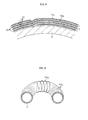
Fig. 4] Fig. 4 illustrates an enlarged view of the portion indicated by IV ofFig. 2 . - [
Fig. 5] Fig. 5 illustrates an enlarged view of the portion indicated by V (lamination starting point of a latitudinal reinforcing fiber layer) ofFig 3 . - [
Fig. 6] Fig. 6 illustrates a cross-sectional perspective view of the pressure vessel. - [
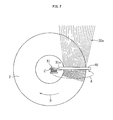
Fig. 7] Fig. 7 illustrates a schematic plan view illustrating a method of manufacturing the pressure vessel. - [
Fig. 8] Fig. 8 illustrates a schematic cross-sectional view illustrating the method of manufacturing the pressure vessel in the meridional direction. - [
Fig. 9] Fig. 9 illustrates a schematic cross-sectional view on magnified scale illustrating the method of manufacturing the pressure vessel in the latitudinal direction. - An embodiment of the present invention is described hereinafter based on the drawings.
- As illustrated in
Fig. 1 , apressure vessel 1 according to this embodiment has a toroidal shape formed of an annular-shaped hollow tube. An axis of the toroidal shape is indicated by C, a meridional direction is indicated by M, and a latitudinal direction is indicated by L. As illustrated inFig. 2 (cross-section in the meridional direction M) andFig. 3 (cross-section in the latitudinal direction L), thepressure vessel 1 includes a toroidalinner vessel 2 and acomposite material layer 3 provided on a surface of theinner vessel 2. Thepressure vessel 1 is adapted for storing high-pressure gas in aninternal space 4 of theinner vessel 2, and for example, used as a fuel tank for storing a fuel gas for an automobile or the like (for example, CNG). Note that, an inlet/outlet port for the high-pressure gas is omitted inFig. 1 . - The
inner vessel 2 has a toroidal shape and is made of metal, for example. As illustrated inFig. 2 andFig. 3 , theinner vessel 2 has a circular shape in both cross-sections in the meridional direction M and in the latitudinal direction L. - The
composite material layer 3 is made by impregnating the reinforcing fiber layers with a resin to be hardened. The reinforcing fiber layers are made of carbon fibers, for example. The resin to be used for impregnating into the reinforcing fiber layers may include, for example, a thermosetting resin and a thermoplastic resin. Specifically, an epoxy resin, bismaleimide, and polyimide, and the like are usable as the thermosetting resin, and polyetheretherketon and the like are usable as the thermoplastic resin. As illustrated inFig. 4 andFig. 5 , the reinforcing fiber layers include meridional reinforcingfiber layers 31 which are formed of reinforcingfibers 31a wound around an outer periphery of theinner vessel 2 in the meridional direction, and latitudinal reinforcingfiber layers 32 which are formed of reinforcingfibers 32a wound around the outer periphery of theinner vessel 2 along the latitudinal direction. The meridional reinforcingfiber layers 31 and the latitudinal reinforcingfiber layers 32 are alternately laminated on an outer peripheral surface of theinner vessel 2. The resin is impregnated into those reinforcingfiber layers composite material layer 3. - As illustrated in
Fig. 6 , the reinforcingfibers 31a constituting the meridional reinforcingfiber layers 31 are continuously arranged around the outer periphery of theinner vessel 2 in a seamless way. In this way, reinforcing thepressure vessel 1 by the meridional reinforcingfiber layers 31 allows expansion of thepressure vessel 1 in the meridional direction to be restricted and pressure resistance in the meridional direction to be improved. Note that, although inFig. 6 the meridional reinforcingfibers 31a are spaced apart from one another in the latitudinal direction for ease of understanding, in fact the reinforcingfibers 31a are arranged with no space therebetween as illustrated inFig. 5 . - There are a plurality of laminated latitudinal reinforcing
fiber layers 32. In this way, reinforcing thepressure vessel 1 by the latitudinal reinforcingfibers 32 allows expansion of thepressure vessel 1 in the latitudinal direction to be restricted and pressure resistance in the latitudinal direction to be improved. In particular, laminating the plurality of reinforcingfiber layers 32 enables to further improve pressure resistance in the latitudinal direction. As illustrated inFig. 6 , the reinforcingfibers 32a constituting the latitudinal reinforcingfiber layers 32 include a plurality of reinforcing fibers aligned with each other in the latitudinal direction. Those reinforcingfibers 32a are not divided for each layer to be laminated, but are arranged continuously from one layer to the next layer. Specifically, as illustrated inFig. 5 , the reinforcingfibers 32a are laminated by continuously winding the reinforcingfibers 32a around theinner vessel 2. Note that, although inFig. 6 the plurality of latitudinal reinforcingfibers 32a are spaced apart from one another in the meridional direction for ease of understanding, in fact the reinforcingfibers 32a are arranged with no space therebetween as illustrated inFig. 4 . - Next, there is described a method of manufacturing the
pressure vessel 1, particularly, a method of arranging the meridional reinforcingfiber layers 31 and the latitudinal reinforcing fiber layers 32 on the surface of the toroidalinner vessel 2. - First, as illustrated in
Fig. 7 , the plurality of latitudinal reinforcingfibers 32a supplied from a supply apparatus (not shown) are aligned with each other on the entire outer peripheral surface of theinner vessel 2 with no space between the reinforcing fibers. Specifically, the plurality of latitudinal reinforcingfibers 32a are supplied to the outer peripheral surface of theinner vessel 2, while being guided by aguide 40 so as to uniformly align with each other in the meridional direction. - At the same time, the
meridional reinforcing fibers 31a are wound around a part of the outer periphery of theinner vessel 2 that has the latitudinal reinforcingfibers 32a arranged. As illustrated inFig. 8 , winding of the meridional reinforcingfibers 31a is performed by asupply apparatus 51 for supplying themeridional reinforcing fibers 31a revolving along anannular rail 52 provided around the outer periphery of the inner vessel 2 (refer to an arrow A ofFig. 7 andFig. 8 ). In this way, by winding themeridional reinforcing fibers 31a around the outer periphery of theinner vessel 2 and over the latitudinal reinforcingfibers 32a, as illustrated inFig. 9 , thelatitudinal reinforcing fibers 32a are fixed to the surface of theinner vessel 2. Note that, themeridional reinforcing fibers 31 may be supplied from thesupply apparatus 51 one by one, or some of the meridional reinforcingfibers 31 may be brought together and supplied from thesupply apparatus 51. - At the same time as the revolution of the
supply apparatus 51 as described above, theinner vessel 2 is rotated about the axis C in an arrow B direction (refer toFig. 7 andFig. 9 ), and, correspondingly, themeridional reinforcing fibers 31a are helically advanced in the latitudinal direction while being wound around the outer periphery of theinner vessel 2 in the meridional direction. As a result, thelatitudinal reinforcing fibers 32a are sequentially fixed to the outer peripheral surface of theinner vessel 2 by themeridional reinforcing fibers 31a while being supplied around the outer peripheral surface of theinner vessel 2. Specifically, theinner vessel 2 is rotated about the axis C by a width W in the latitudinal direction (refer toFig. 9 ) of the meridional reinforcingfibers 31a during one revolution of thesupply apparatus 51 around the outer periphery of theinner vessel 2 along theannular rail 52, thereby winding themeridional reinforcing fibers 31a on theinner vessel 2 with no space between the reinforcing fibers. Thus, the latitudinal reinforcingfiber layers 32 and the meridional reinforcingfiber layers 31 are sequentially formed as theinner vessel 2 is rotated about the axis C. - After one rotation of the
inner vessel 2 about the axis C, the latitudinal reinforcingfiber layer 32 and the meridional reinforcingfiber layer 31 in the second round are overlaid on the outer periphery of the previously fixed latitudinal reinforcingfiber layer 32 and the meridional reinforcingfiber layer 31 in the first round. Thus, thelatitudinal reinforcing fibers 32a are supplied around the outer peripheral surface of theinner vessel 2, while themeridional reinforcing fibers 31a are continuously and helically wound around the outer periphery thereof, thereby making it possible to continuously supply thelatitudinal reinforcing fibers 32a and the meridional reinforcingfibers 31a in a seamless way and alternately laminate each reinforcingfiber layer 31, 32 (refer toFig. 5 ). Note that, although approximately four meridional reinforcingfiber layers 31 and approximately four latitudinal reinforcingfiber layers 32 are laminated in this embodiment, the number of laminated layers is not limited by this number and appropriately determined depending on the required strength and acceptable weight. - Now, in the case of the
pressure vessel 1 as described above, a fiber orientation ratio of the meridional reinforcingfiber layers 31 and the latitudinal reinforcing fiber layers 32 (density ratio of the reinforcing fibers in each direction) can be freely determined. In other words, a density of the reinforcingfibers 31a in the meridional reinforcingfiber layers 31 and a density of the reinforcingfibers 32a in the latitudinal reinforcingfiber layers 32 can be determined as appropriate for the required strength in each direction. The density of the latitudinal reinforcingfibers 32a can be adjusted by the number of the latitudinal reinforcingfibers 32a supplied from the supply apparatus (not shown). On the other hand, the density of the meridional reinforcingfibers 31a can be adjusted by adjusting a ratio of a rotational speed of theinner vessel 2 about the axis C and a supply speed of the latitudinal reinforcingfibers 32a. - The reinforcing fiber layers 31, 32 thus fixed to the surface of the
inner vessel 2 are impregnated with the resin (for example, thermosetting resin or thermoplastic resin described above). Subsequently, the resin is cured by heating (or at room temperature), thereby forming thecomposite material layer 3. Subsequently, a gas inlet/outlet port (not shown) is formed to complete thepressure vessel 1, the gas inlet/outlet port extending through theinner vessel 2 and thecomposite material layer 3 so as to make theinternal space 4 communicate to an external space. - The present invention is not limited to the above-mentioned embodiment. For example, although the case where the
pressure vessel 1 has a circular shape in both cross-sections in the meridional direction and in the latitudinal direction is described in the above-mentioned embodiment, for example, thepressure vessel 1 may be oval or of a shape partially having straight parts in one cross-section or both cross-sections, without limitation. However, in view of an extremely high pressure applied to thepressure vessel 1 by the high-pressure gas stored therein, it is preferred to have thepressure vessel 1 which is circular in both cross-sections in the meridional direction and in the latitudinal direction as the above-mentioned embodiment, to thereby ensure that no stress concentration is formed. - Further, although in the above-mentioned embodiment the reinforcing fiber layers 31, 32 are fixed to the
inner vessel 2 before the resin is impregnated into the reinforcing fiber layers and hardened, for example, the reinforcingfibers inner vessel 2 before hardening of the resin, without limitation. -
- 1
- pressure vessel
- 2
- inner vessel
- 3
- composite material layer
- 31
- meridional reinforcing fiber layer
- 31a
- meridional reinforcing fiber
- 32
- latitudinal reinforcing fiber layer
- 32a
- latitudinal reinforcing fiber
- 4
- internal space
- 40
- guide
- 51
- supply apparatus
- 52
- annular rail
- C
- axis
- L
- latitudinal direction
- M
- meridional direction
Claims (6)
- A pressure vessel, comprising:a toroidal inner vessel formed of an annular-shaped hollow tube;meridional reinforcing fiber layers formed of reinforcing fibers wound around an outer peripheral surface of the inner vessel along a meridional direction; andlatitudinal reinforcing fiber layers formed of reinforcing fibers wound around the outer peripheral surface of the inner vessel along a latitudinal direction,wherein the latitudinal reinforcing fiber layers are laminated in a plurality of layers around the outer peripheral surface of the inner vessel, and the reinforcing fibers constituting each of the plurality of layers thus laminated are continuous from one layer to a next layer.
- A pressure vessel according to claim 1, wherein the latitudinal reinforcing fiber layers and the meridional reinforcing fiber layers are alternately laminated.
- A pressure vessel according to claim 1 or 2, wherein the inner vessel has a circular shape in both cross-sections in the latitudinal direction and in the meridional direction.
- A pressure vessel according to any one of claims 1 to 3, wherein the reinforcing fibers constituting the latitudinal reinforcing fiber layers are arranged around the outer peripheral surface of the inner vessel with no space between the reinforcing fibers.
- A method of manufacturing a pressure vessel, the pressure vessel comprising: a toroidal inner vessel formed of an annular-shaped hollow tube; meridional reinforcing fiber layers formed of reinforcing fibers wound around an outer peripheral surface of the inner vessel along a meridional direction; and latitudinal reinforcing fiber layers formed of the reinforcing fibers wound around the outer peripheral surface of the inner vessel along a latitudinal direction,
the method comprising arranging the reinforcing fibers around the outer peripheral surface of the inner vessel along the latitudinal direction, while winding another reinforcing fibers around an outer periphery of the inner vessel and over the latitudinal reinforcing fibers along the meridional direction, thereby fixing the latitudinal reinforcing fiber layers to the inner vessel. - A method of manufacturing a pressure vessel according to claim 5, wherein the meridional reinforcing fibers are helically advanced in the latitudinal direction while being wound in the meridional direction, thereby alternately laminating the latitudinal reinforcing fiber layers and the meridional reinforcing fiber layers.
Applications Claiming Priority (1)
| Application Number | Priority Date | Filing Date | Title |
|---|---|---|---|
| JP2010172453A JP5220811B2 (en) | 2010-07-30 | 2010-07-30 | Pressure vessel and method for manufacturing the same |
Publications (2)
| Publication Number | Publication Date |
|---|---|
| EP2412514A1 true EP2412514A1 (en) | 2012-02-01 |
| EP2412514B1 EP2412514B1 (en) | 2015-09-23 |
Family
ID=44862883
Family Applications (1)
| Application Number | Title | Priority Date | Filing Date |
|---|---|---|---|
| EP11401557.1A Active EP2412514B1 (en) | 2010-07-30 | 2011-07-22 | Toroidal pressure vessel and method of manufacturing the same |
Country Status (4)
| Country | Link |
|---|---|
| US (1) | US8991641B2 (en) |
| EP (1) | EP2412514B1 (en) |
| JP (1) | JP5220811B2 (en) |
| ES (1) | ES2556142T3 (en) |
Families Citing this family (4)
| Publication number | Priority date | Publication date | Assignee | Title |
|---|---|---|---|---|
| US9541235B2 (en) * | 2011-02-17 | 2017-01-10 | Raytheon Company | Belted toroid pressure vessel and method for making the same |
| JP6266293B2 (en) * | 2013-10-09 | 2018-01-24 | 三菱重工業株式会社 | Pressure vessel and method for manufacturing the same |
| JP6223108B2 (en) * | 2013-10-09 | 2017-11-01 | 三菱重工業株式会社 | Pressure vessel and method for manufacturing the same |
| KR101595863B1 (en) * | 2015-05-26 | 2016-02-22 | 주식회사 카본티씨지 | Apparatus for making donut type gas tank and donut type gas tank made by the same |
Citations (4)
| Publication number | Priority date | Publication date | Assignee | Title |
|---|---|---|---|---|
| GB2110566A (en) * | 1981-12-03 | 1983-06-22 | Messerschmitt Boelkow Blohm | Torus-shaped pressure vessel |
| EP0172098A1 (en) * | 1984-08-10 | 1986-02-19 | Commissariat à l'Energie Atomique | Method of manufacturing an annular composite body reinforced with orthogonal fibres |
| WO1997012175A1 (en) * | 1995-09-23 | 1997-04-03 | The Secretary Of State For Defence | Gas containment apparatus |
| WO2006076384A2 (en) * | 2005-01-11 | 2006-07-20 | Abraham Keith Allen | Centerless and openable tool carrier for processing of complex shapes |
Family Cites Families (7)
| Publication number | Priority date | Publication date | Assignee | Title |
|---|---|---|---|---|
| US3121451A (en) * | 1959-12-14 | 1964-02-18 | Hans U Schuerch | Isotensoid structure |
| US3864188A (en) * | 1973-04-16 | 1975-02-04 | Caterpillar Tractor Co | Tire Wrapping Machine |
| FR2474136A1 (en) * | 1980-01-17 | 1981-07-24 | Europ Propulsion | ANNULAR THREE-DIMENSIONAL STRUCTURE |
| DE3316539C1 (en) * | 1983-05-06 | 1984-04-05 | Messerschmitt-Bölkow-Blohm GmbH, 8000 München | Toroidal pressure vessel made of composite material |
| JPH0781225B2 (en) * | 1990-08-27 | 1995-08-30 | 株式会社豊田自動織機製作所 | Three-dimensional fabric for connecting members |
| NL1014290C2 (en) * | 2000-02-04 | 2001-08-07 | Advanced Lightweight Const Gro | Fiber-reinforced pressure vessel and method for making a fiber-reinforced pressure vessel. |
| WO2010019966A2 (en) * | 2008-08-15 | 2010-02-18 | Sigma-Tek, Llc | Method & system for forming composite lattice support structures |
-
2010
- 2010-07-30 JP JP2010172453A patent/JP5220811B2/en active Active
-
2011
- 2011-04-15 US US13/087,495 patent/US8991641B2/en active Active
- 2011-07-22 ES ES11401557.1T patent/ES2556142T3/en active Active
- 2011-07-22 EP EP11401557.1A patent/EP2412514B1/en active Active
Patent Citations (4)
| Publication number | Priority date | Publication date | Assignee | Title |
|---|---|---|---|---|
| GB2110566A (en) * | 1981-12-03 | 1983-06-22 | Messerschmitt Boelkow Blohm | Torus-shaped pressure vessel |
| EP0172098A1 (en) * | 1984-08-10 | 1986-02-19 | Commissariat à l'Energie Atomique | Method of manufacturing an annular composite body reinforced with orthogonal fibres |
| WO1997012175A1 (en) * | 1995-09-23 | 1997-04-03 | The Secretary Of State For Defence | Gas containment apparatus |
| WO2006076384A2 (en) * | 2005-01-11 | 2006-07-20 | Abraham Keith Allen | Centerless and openable tool carrier for processing of complex shapes |
Also Published As
| Publication number | Publication date |
|---|---|
| JP2012031938A (en) | 2012-02-16 |
| EP2412514B1 (en) | 2015-09-23 |
| US8991641B2 (en) | 2015-03-31 |
| JP5220811B2 (en) | 2013-06-26 |
| ES2556142T3 (en) | 2016-01-13 |
| US20120024866A1 (en) | 2012-02-02 |
Similar Documents
| Publication | Publication Date | Title |
|---|---|---|
| EP2581638B1 (en) | High-pressure tank and manufacturing method of high pressure tank. | |
| EP2418411B1 (en) | Structure and manufacturing method for pressure container | |
| CA2671831C (en) | Part manufacturing method, part, and tank | |
| US20150192251A1 (en) | High pressure carbon composite pressure vessel | |
| RU2598936C1 (en) | Cylindrical casing and method of making cylindrical casing | |
| US20090314785A1 (en) | Damage and leakage barrier in all-composite pressure vessels and storage tanks | |
| US11384902B2 (en) | Pressure vessel and method for winding filament | |
| US8991641B2 (en) | Pressure vessel and method of manufacturing the same | |
| EP2670582B1 (en) | Manufacturing method for high-pressure tank, and high-pressure tank | |
| KR20160142234A (en) | Manufacturing method of tank | |
| JP2008169893A (en) | Pressure vessel and method for manufacturing the same | |
| JP2018149737A (en) | Method of manufacturing reinforcing layer | |
| US20220065400A1 (en) | Tank production method and tank | |
| KR102805248B1 (en) | A pressure vessel for storing fluid | |
| JP2005106142A (en) | Pressure vessel | |
| JP6726408B2 (en) | High pressure tank manufacturing method and high pressure tank | |
| JP2021014856A (en) | High pressure tank | |
| JP6223108B2 (en) | Pressure vessel and method for manufacturing the same | |
| JP6266293B2 (en) | Pressure vessel and method for manufacturing the same | |
| EP2853376B1 (en) | Composite materials | |
| EP3795860A1 (en) | Bevel gear component, bevel gear, and bevel gear component manufacturing method |
Legal Events
| Date | Code | Title | Description |
|---|---|---|---|
| AK | Designated contracting states |
Kind code of ref document: A1 Designated state(s): AL AT BE BG CH CY CZ DE DK EE ES FI FR GB GR HR HU IE IS IT LI LT LU LV MC MK MT NL NO PL PT RO RS SE SI SK SM TR |
|
| AX | Request for extension of the european patent |
Extension state: BA ME |
|
| PUAI | Public reference made under article 153(3) epc to a published international application that has entered the european phase |
Free format text: ORIGINAL CODE: 0009012 |
|
| 17P | Request for examination filed |
Effective date: 20120719 |
|
| 17Q | First examination report despatched |
Effective date: 20131024 |
|
| GRAP | Despatch of communication of intention to grant a patent |
Free format text: ORIGINAL CODE: EPIDOSNIGR1 |
|
| INTG | Intention to grant announced |
Effective date: 20150408 |
|
| GRAS | Grant fee paid |
Free format text: ORIGINAL CODE: EPIDOSNIGR3 |
|
| GRAA | (expected) grant |
Free format text: ORIGINAL CODE: 0009210 |
|
| AK | Designated contracting states |
Kind code of ref document: B1 Designated state(s): AL AT BE BG CH CY CZ DE DK EE ES FI FR GB GR HR HU IE IS IT LI LT LU LV MC MK MT NL NO PL PT RO RS SE SI SK SM TR |
|
| REG | Reference to a national code |
Ref country code: GB Ref legal event code: FG4D |
|
| REG | Reference to a national code |
Ref country code: CH Ref legal event code: EP |
|
| REG | Reference to a national code |
Ref country code: AT Ref legal event code: REF Ref document number: 750991 Country of ref document: AT Kind code of ref document: T Effective date: 20151015 |
|
| REG | Reference to a national code |
Ref country code: IE Ref legal event code: FG4D |
|
| REG | Reference to a national code |
Ref country code: DE Ref legal event code: R096 Ref document number: 602011019976 Country of ref document: DE |
|
| REG | Reference to a national code |
Ref country code: SE Ref legal event code: TRGR |
|
| REG | Reference to a national code |
Ref country code: ES Ref legal event code: FG2A Ref document number: 2556142 Country of ref document: ES Kind code of ref document: T3 Effective date: 20160113 |
|
| REG | Reference to a national code |
Ref country code: NL Ref legal event code: MP Effective date: 20150923 |
|
| PG25 | Lapsed in a contracting state [announced via postgrant information from national office to epo] |
Ref country code: GR Free format text: LAPSE BECAUSE OF FAILURE TO SUBMIT A TRANSLATION OF THE DESCRIPTION OR TO PAY THE FEE WITHIN THE PRESCRIBED TIME-LIMIT Effective date: 20151224 Ref country code: NO Free format text: LAPSE BECAUSE OF FAILURE TO SUBMIT A TRANSLATION OF THE DESCRIPTION OR TO PAY THE FEE WITHIN THE PRESCRIBED TIME-LIMIT Effective date: 20151223 Ref country code: FI Free format text: LAPSE BECAUSE OF FAILURE TO SUBMIT A TRANSLATION OF THE DESCRIPTION OR TO PAY THE FEE WITHIN THE PRESCRIBED TIME-LIMIT Effective date: 20150923 Ref country code: LT Free format text: LAPSE BECAUSE OF FAILURE TO SUBMIT A TRANSLATION OF THE DESCRIPTION OR TO PAY THE FEE WITHIN THE PRESCRIBED TIME-LIMIT Effective date: 20150923 Ref country code: LV Free format text: LAPSE BECAUSE OF FAILURE TO SUBMIT A TRANSLATION OF THE DESCRIPTION OR TO PAY THE FEE WITHIN THE PRESCRIBED TIME-LIMIT Effective date: 20150923 |
|
| REG | Reference to a national code |
Ref country code: LT Ref legal event code: MG4D |
|
| REG | Reference to a national code |
Ref country code: AT Ref legal event code: MK05 Ref document number: 750991 Country of ref document: AT Kind code of ref document: T Effective date: 20150923 |
|
| PG25 | Lapsed in a contracting state [announced via postgrant information from national office to epo] |
Ref country code: RS Free format text: LAPSE BECAUSE OF FAILURE TO SUBMIT A TRANSLATION OF THE DESCRIPTION OR TO PAY THE FEE WITHIN THE PRESCRIBED TIME-LIMIT Effective date: 20150923 Ref country code: HR Free format text: LAPSE BECAUSE OF FAILURE TO SUBMIT A TRANSLATION OF THE DESCRIPTION OR TO PAY THE FEE WITHIN THE PRESCRIBED TIME-LIMIT Effective date: 20150923 |
|
| PG25 | Lapsed in a contracting state [announced via postgrant information from national office to epo] |
Ref country code: NL Free format text: LAPSE BECAUSE OF FAILURE TO SUBMIT A TRANSLATION OF THE DESCRIPTION OR TO PAY THE FEE WITHIN THE PRESCRIBED TIME-LIMIT Effective date: 20150923 |
|
| PG25 | Lapsed in a contracting state [announced via postgrant information from national office to epo] |
Ref country code: SK Free format text: LAPSE BECAUSE OF FAILURE TO SUBMIT A TRANSLATION OF THE DESCRIPTION OR TO PAY THE FEE WITHIN THE PRESCRIBED TIME-LIMIT Effective date: 20150923 Ref country code: EE Free format text: LAPSE BECAUSE OF FAILURE TO SUBMIT A TRANSLATION OF THE DESCRIPTION OR TO PAY THE FEE WITHIN THE PRESCRIBED TIME-LIMIT Effective date: 20150923 Ref country code: CZ Free format text: LAPSE BECAUSE OF FAILURE TO SUBMIT A TRANSLATION OF THE DESCRIPTION OR TO PAY THE FEE WITHIN THE PRESCRIBED TIME-LIMIT Effective date: 20150923 Ref country code: IS Free format text: LAPSE BECAUSE OF FAILURE TO SUBMIT A TRANSLATION OF THE DESCRIPTION OR TO PAY THE FEE WITHIN THE PRESCRIBED TIME-LIMIT Effective date: 20160123 |
|
| PG25 | Lapsed in a contracting state [announced via postgrant information from national office to epo] |
Ref country code: PT Free format text: LAPSE BECAUSE OF FAILURE TO SUBMIT A TRANSLATION OF THE DESCRIPTION OR TO PAY THE FEE WITHIN THE PRESCRIBED TIME-LIMIT Effective date: 20160125 Ref country code: AT Free format text: LAPSE BECAUSE OF FAILURE TO SUBMIT A TRANSLATION OF THE DESCRIPTION OR TO PAY THE FEE WITHIN THE PRESCRIBED TIME-LIMIT Effective date: 20150923 Ref country code: PL Free format text: LAPSE BECAUSE OF FAILURE TO SUBMIT A TRANSLATION OF THE DESCRIPTION OR TO PAY THE FEE WITHIN THE PRESCRIBED TIME-LIMIT Effective date: 20150923 Ref country code: RO Free format text: LAPSE BECAUSE OF FAILURE TO SUBMIT A TRANSLATION OF THE DESCRIPTION OR TO PAY THE FEE WITHIN THE PRESCRIBED TIME-LIMIT Effective date: 20150923 |
|
| REG | Reference to a national code |
Ref country code: DE Ref legal event code: R097 Ref document number: 602011019976 Country of ref document: DE |
|
| REG | Reference to a national code |
Ref country code: FR Ref legal event code: PLFP Year of fee payment: 6 |
|
| PLBE | No opposition filed within time limit |
Free format text: ORIGINAL CODE: 0009261 |
|
| STAA | Information on the status of an ep patent application or granted ep patent |
Free format text: STATUS: NO OPPOSITION FILED WITHIN TIME LIMIT |
|
| 26N | No opposition filed |
Effective date: 20160624 |
|
| PG25 | Lapsed in a contracting state [announced via postgrant information from national office to epo] |
Ref country code: DK Free format text: LAPSE BECAUSE OF FAILURE TO SUBMIT A TRANSLATION OF THE DESCRIPTION OR TO PAY THE FEE WITHIN THE PRESCRIBED TIME-LIMIT Effective date: 20150923 |
|
| PG25 | Lapsed in a contracting state [announced via postgrant information from national office to epo] |
Ref country code: SI Free format text: LAPSE BECAUSE OF FAILURE TO SUBMIT A TRANSLATION OF THE DESCRIPTION OR TO PAY THE FEE WITHIN THE PRESCRIBED TIME-LIMIT Effective date: 20150923 |
|
| PG25 | Lapsed in a contracting state [announced via postgrant information from national office to epo] |
Ref country code: BE Free format text: LAPSE BECAUSE OF FAILURE TO SUBMIT A TRANSLATION OF THE DESCRIPTION OR TO PAY THE FEE WITHIN THE PRESCRIBED TIME-LIMIT Effective date: 20150923 |
|
| REG | Reference to a national code |
Ref country code: CH Ref legal event code: PL |
|
| PG25 | Lapsed in a contracting state [announced via postgrant information from national office to epo] |
Ref country code: MC Free format text: LAPSE BECAUSE OF FAILURE TO SUBMIT A TRANSLATION OF THE DESCRIPTION OR TO PAY THE FEE WITHIN THE PRESCRIBED TIME-LIMIT Effective date: 20150923 |
|
| PG25 | Lapsed in a contracting state [announced via postgrant information from national office to epo] |
Ref country code: LI Free format text: LAPSE BECAUSE OF NON-PAYMENT OF DUE FEES Effective date: 20160731 Ref country code: CH Free format text: LAPSE BECAUSE OF NON-PAYMENT OF DUE FEES Effective date: 20160731 |
|
| REG | Reference to a national code |
Ref country code: IE Ref legal event code: MM4A |
|
| REG | Reference to a national code |
Ref country code: FR Ref legal event code: PLFP Year of fee payment: 7 |
|
| PG25 | Lapsed in a contracting state [announced via postgrant information from national office to epo] |
Ref country code: IE Free format text: LAPSE BECAUSE OF NON-PAYMENT OF DUE FEES Effective date: 20160722 |
|
| PG25 | Lapsed in a contracting state [announced via postgrant information from national office to epo] |
Ref country code: LU Free format text: LAPSE BECAUSE OF NON-PAYMENT OF DUE FEES Effective date: 20160722 |
|
| PG25 | Lapsed in a contracting state [announced via postgrant information from national office to epo] |
Ref country code: CY Free format text: LAPSE BECAUSE OF FAILURE TO SUBMIT A TRANSLATION OF THE DESCRIPTION OR TO PAY THE FEE WITHIN THE PRESCRIBED TIME-LIMIT Effective date: 20150923 Ref country code: SM Free format text: LAPSE BECAUSE OF FAILURE TO SUBMIT A TRANSLATION OF THE DESCRIPTION OR TO PAY THE FEE WITHIN THE PRESCRIBED TIME-LIMIT Effective date: 20150923 Ref country code: HU Free format text: LAPSE BECAUSE OF FAILURE TO SUBMIT A TRANSLATION OF THE DESCRIPTION OR TO PAY THE FEE WITHIN THE PRESCRIBED TIME-LIMIT; INVALID AB INITIO Effective date: 20110722 |
|
| PG25 | Lapsed in a contracting state [announced via postgrant information from national office to epo] |
Ref country code: MT Free format text: LAPSE BECAUSE OF NON-PAYMENT OF DUE FEES Effective date: 20160731 Ref country code: MK Free format text: LAPSE BECAUSE OF FAILURE TO SUBMIT A TRANSLATION OF THE DESCRIPTION OR TO PAY THE FEE WITHIN THE PRESCRIBED TIME-LIMIT Effective date: 20150923 Ref country code: TR Free format text: LAPSE BECAUSE OF FAILURE TO SUBMIT A TRANSLATION OF THE DESCRIPTION OR TO PAY THE FEE WITHIN THE PRESCRIBED TIME-LIMIT Effective date: 20150923 |
|
| REG | Reference to a national code |
Ref country code: FR Ref legal event code: PLFP Year of fee payment: 8 |
|
| PG25 | Lapsed in a contracting state [announced via postgrant information from national office to epo] |
Ref country code: BG Free format text: LAPSE BECAUSE OF FAILURE TO SUBMIT A TRANSLATION OF THE DESCRIPTION OR TO PAY THE FEE WITHIN THE PRESCRIBED TIME-LIMIT Effective date: 20150923 |
|
| PG25 | Lapsed in a contracting state [announced via postgrant information from national office to epo] |
Ref country code: AL Free format text: LAPSE BECAUSE OF FAILURE TO SUBMIT A TRANSLATION OF THE DESCRIPTION OR TO PAY THE FEE WITHIN THE PRESCRIBED TIME-LIMIT Effective date: 20150923 |
|
| PGFP | Annual fee paid to national office [announced via postgrant information from national office to epo] |
Ref country code: GB Payment date: 20250604 Year of fee payment: 15 |
|
| PGFP | Annual fee paid to national office [announced via postgrant information from national office to epo] |
Ref country code: ES Payment date: 20250819 Year of fee payment: 15 |
|
| PGFP | Annual fee paid to national office [announced via postgrant information from national office to epo] |
Ref country code: DE Payment date: 20250625 Year of fee payment: 15 |
|
| PGFP | Annual fee paid to national office [announced via postgrant information from national office to epo] |
Ref country code: IT Payment date: 20250731 Year of fee payment: 15 |
|
| PGFP | Annual fee paid to national office [announced via postgrant information from national office to epo] |
Ref country code: FR Payment date: 20250723 Year of fee payment: 15 |
|
| PGFP | Annual fee paid to national office [announced via postgrant information from national office to epo] |
Ref country code: SE Payment date: 20250723 Year of fee payment: 15 |