EP2412309A1 - Measuring instrument and measurement method - Google Patents
Measuring instrument and measurement method Download PDFInfo
- Publication number
- EP2412309A1 EP2412309A1 EP10756180A EP10756180A EP2412309A1 EP 2412309 A1 EP2412309 A1 EP 2412309A1 EP 10756180 A EP10756180 A EP 10756180A EP 10756180 A EP10756180 A EP 10756180A EP 2412309 A1 EP2412309 A1 EP 2412309A1
- Authority
- EP
- European Patent Office
- Prior art keywords
- magnetic
- field generating
- generating means
- indicates
- encoding
- Prior art date
- Legal status (The legal status is an assumption and is not a legal conclusion. Google has not performed a legal analysis and makes no representation as to the accuracy of the status listed.)
- Withdrawn
Links
Images


Classifications
-
- G—PHYSICS
- G01—MEASURING; TESTING
- G01R—MEASURING ELECTRIC VARIABLES; MEASURING MAGNETIC VARIABLES
- G01R33/00—Arrangements or instruments for measuring magnetic variables
- G01R33/20—Arrangements or instruments for measuring magnetic variables involving magnetic resonance
- G01R33/44—Arrangements or instruments for measuring magnetic variables involving magnetic resonance using nuclear magnetic resonance [NMR]
- G01R33/48—NMR imaging systems
- G01R33/4808—Multimodal MR, e.g. MR combined with positron emission tomography [PET], MR combined with ultrasound or MR combined with computed tomography [CT]
-
- A—HUMAN NECESSITIES
- A61—MEDICAL OR VETERINARY SCIENCE; HYGIENE
- A61B—DIAGNOSIS; SURGERY; IDENTIFICATION
- A61B5/00—Measuring for diagnostic purposes; Identification of persons
- A61B5/05—Detecting, measuring or recording for diagnosis by means of electric currents or magnetic fields; Measuring using microwaves or radio waves
- A61B5/055—Detecting, measuring or recording for diagnosis by means of electric currents or magnetic fields; Measuring using microwaves or radio waves involving electronic [EMR] or nuclear [NMR] magnetic resonance, e.g. magnetic resonance imaging
-
- G—PHYSICS
- G01—MEASURING; TESTING
- G01R—MEASURING ELECTRIC VARIABLES; MEASURING MAGNETIC VARIABLES
- G01R33/00—Arrangements or instruments for measuring magnetic variables
- G01R33/20—Arrangements or instruments for measuring magnetic variables involving magnetic resonance
- G01R33/44—Arrangements or instruments for measuring magnetic variables involving magnetic resonance using nuclear magnetic resonance [NMR]
- G01R33/48—NMR imaging systems
- G01R33/54—Signal processing systems, e.g. using pulse sequences ; Generation or control of pulse sequences; Operator console
- G01R33/56—Image enhancement or correction, e.g. subtraction or averaging techniques, e.g. improvement of signal-to-noise ratio and resolution
- G01R33/563—Image enhancement or correction, e.g. subtraction or averaging techniques, e.g. improvement of signal-to-noise ratio and resolution of moving material, e.g. flow contrast angiography
- G01R33/56375—Intentional motion of the sample during MR, e.g. moving table imaging
- G01R33/56383—Intentional motion of the sample during MR, e.g. moving table imaging involving motion of the sample as a whole, e.g. multistation MR or MR with continuous table motion
-
- G—PHYSICS
- G01—MEASURING; TESTING
- G01R—MEASURING ELECTRIC VARIABLES; MEASURING MAGNETIC VARIABLES
- G01R33/00—Arrangements or instruments for measuring magnetic variables
- G01R33/20—Arrangements or instruments for measuring magnetic variables involving magnetic resonance
- G01R33/44—Arrangements or instruments for measuring magnetic variables involving magnetic resonance using nuclear magnetic resonance [NMR]
- G01R33/48—NMR imaging systems
- G01R33/54—Signal processing systems, e.g. using pulse sequences ; Generation or control of pulse sequences; Operator console
- G01R33/56—Image enhancement or correction, e.g. subtraction or averaging techniques, e.g. improvement of signal-to-noise ratio and resolution
- G01R33/565—Correction of image distortions, e.g. due to magnetic field inhomogeneities
- G01R33/56509—Correction of image distortions, e.g. due to magnetic field inhomogeneities due to motion, displacement or flow, e.g. gradient moment nulling
-
- G—PHYSICS
- G01—MEASURING; TESTING
- G01R—MEASURING ELECTRIC VARIABLES; MEASURING MAGNETIC VARIABLES
- G01R33/00—Arrangements or instruments for measuring magnetic variables
- G01R33/20—Arrangements or instruments for measuring magnetic variables involving magnetic resonance
- G01R33/60—Arrangements or instruments for measuring magnetic variables involving magnetic resonance using electron paramagnetic resonance
-
- G—PHYSICS
- G01—MEASURING; TESTING
- G01R—MEASURING ELECTRIC VARIABLES; MEASURING MAGNETIC VARIABLES
- G01R33/00—Arrangements or instruments for measuring magnetic variables
- G01R33/20—Arrangements or instruments for measuring magnetic variables involving magnetic resonance
- G01R33/28—Details of apparatus provided for in groups G01R33/44 - G01R33/64
- G01R33/38—Systems for generation, homogenisation or stabilisation of the main or gradient magnetic field
- G01R33/3806—Open magnet assemblies for improved access to the sample, e.g. C-type or U-type magnets
-
- G—PHYSICS
- G01—MEASURING; TESTING
- G01R—MEASURING ELECTRIC VARIABLES; MEASURING MAGNETIC VARIABLES
- G01R33/00—Arrangements or instruments for measuring magnetic variables
- G01R33/20—Arrangements or instruments for measuring magnetic variables involving magnetic resonance
- G01R33/44—Arrangements or instruments for measuring magnetic variables involving magnetic resonance using nuclear magnetic resonance [NMR]
- G01R33/445—MR involving a non-standard magnetic field B0, e.g. of low magnitude as in the earth's magnetic field or in nanoTesla spectroscopy, comprising a polarizing magnetic field for pre-polarisation, B0 with a temporal variation of its magnitude or direction such as field cycling of B0 or rotation of the direction of B0, or spatially inhomogeneous B0 like in fringe-field MR or in stray-field imaging
Definitions
- the invention relates to a measurement device and a measurement method for obtaining images of an object, such as functional images and morphologic images, by virtue of various magnetic resonances such as electron spin resonance (ESR) and nuclear magnetic resonance (NMR).
- ESR electron spin resonance
- NMR nuclear magnetic resonance
- Redox metabolism containing active oxygen and free radicals is much concerned with a lot of physiological phenomena, and causes and development of diseases. Accordingly, if redox dynamics in a laboratory animal could be visualized at an individual level, it would be possible without doubt to contribute to elucidation of life phenomenon, analysis of diseases, establishment of curing diseases, and development of medicines.
- Electron spin resonance imaging in accordance with which free radicals as intermediate products of redox metabolism are peculiarly detected, is useful for visualizing redox dynamics.
- images resulted from ESRI lack correspondence with internal organs.
- an ESRI-MRI combination type apparatus for analyzing magnetic resonance images in which images resulted from ESRI are superimposed with MRI images of internal organs obtained by nuclear magnetic resonance imaging (MRI).
- Overhauser effect is a phenomenon in which electron spin of free radicals is made to be ESR-transited to thereby cause nuclear spin to be polarized by virtue of dipole-dipole interaction between electron spin and nuclear spin.
- OMRI is an imaging process in which after electron spin of free radicals is excited, hydrogen nuclear spin of water molecule is polarized for carrying out MRI measurement.
- nuclear spin polarization is 330-times intensified at maximum (theoretical value) in comparison with Boltzmann distribution of usual nuclear spin. That is, OMRI makes it possible to realize 330-times sensitization (theoretical value) in comparison with usual MRI measurement.
- the inventors of the present application suggested, in the patent reference 1, the measurement device for obtaining images of organism structures by virtue of various magnetic resonances such as electron spin resonance and nuclear magnetic resonance.
- the measurement device is designed to include means for generating a first magnetic field having a certain intensity, means for generating a second magnetic field having an intensity greater than the intensity of the first magnetic field, means for linearly moving an object between the first magnetic field generating means and the second magnetic field generating means in synchronization with irradiation of RF pulses onto the object, and means for stopping the object to move, and obtaining images of organism structure of the object in accordance with signals detected in response to the RF pulses.
- the means for generating a first magnetic field may be employed as both an apparatus for generating an external magnetic field for ESRI and an apparatus for exciting electron spin for PEDRI (OMRI), and the means for generating a second magnetic field may be employed as an apparatus for generating an external magnetic field for MRI and OMRI.
- images of an amount of radicals varying with the lapse of time are obtained by OMRI, and images of radicals varying in quality are obtained by spectrum/spatial four-dimensional ESRI/MRI, and further, a magnetic field generated by the means for generating a second magnetic field can be designed to have a high intensity, resulting in that it is possible to obtain images having high sensitivity and high resolution.
- the means for linearly moving an object disposed between the first magnetic field generating means and the second magnetic field generating means, causes the object to reciprocatingly move, and after the object is caused to stop, the measurement is carried out.
- high acceleration is applied to the object when the object starts moving and is stopped. Consequently, the above-mentioned measurement device is accompanied with a problem that high load is unavoidably applied to the organism as the object while moving.
- the inventors are presently developing a measurement device which is able to measure an object moving between a plurality of magnetic field generating means, without stopping the object to thereby avoid the object from being loaded.
- measuring an object without stopping the object there newly arises a problem that images of the object are influenced by a moving velocity, and resultingly, images of the object are shifted.
- an object of the present invention to provide a measurement device and a measurement method for obtaining images of an object to be measured such as functional images and morphologic images by virtue of magnetic resonance, both of which are capable of providing accurate images by eliminating influences caused by a moving velocity to a moving object.
- a measurement device for obtaining images of an object to be measured by virtue of magnetic resonance includes magnetic-field generating means for generating a magnetic field to excite magnetic resonance of the object, moving means for moving one of the object and the magnetic-field generating means to thereby move the object in a magnetic field generated by the magnetic-field generating means, measurement means for applying a gradient magnetic field in at least one of a moving direction "y" in which the object moves relative to the magnetic-field generating means, and a direction "x" perpendicular to the moving direction "y” to thereby obtain image signals of the object by virtue of at least one of phase-encoding and frequency-encoding without stopping the object or the magnetic-field generating means while they are being moved by the moving means, and correction means for eliminating influence on the image signals derived from movement of the object in the moving direction "y” to provide corrected image signals.
- a measurement method for obtaining images of an object to be measured by virtue of magnetic resonance includes moving one of the object and magnetic-field generating means which generates a magnetic field to excite magnetic resonance of the object to thereby move the object through a magnetic field generated by the magnetic-field generating means, applying a gradient magnetic field in at least one of a moving direction "y" in which the object moves relative to the magnetic-field generating means, and a direction "x" perpendicular to the moving direction "y” to thereby obtain image signals of the object by virtue of at least one of phase-encoding and frequency-encoding without stopping the object or the magnetic-field generating means while they are being moved, and eliminating influence on the image signals derived from movement of the object in the moving direction "y” to provide corrected image signals.
- S (k x , k y ) indicates the image signals
- S'(k x , k y ) indicates the corrected image signals
- each of k x and k y indicates a spatial frequency in the directions "x" and "y” respectively
- y indicates a gyromagnetic ratio
- G y (n) indicates an intensity of a gradient magnetic field of the phase-encoding or the frequency-encoding in n-th measurement
- v y indicates a moving velocity in the moving direction "y”
- ⁇ t y indicates a period of time during which the phase-en
- the corrected image signals S' (k x , k y ) in which the influence on the image signals derived from movement of the object in the moving direction "y", caused by a moving velocity in the moving direction "y", a period of time during which the phase-encoding or the frequency-encoding is applied, and/or a period of time until the phase-encoding or the frequency-encoding starts being applied, is eliminated, ensuring it possible to obtain accurate non-shifted images of the object, such as functional images and morphologic images, in particular, accurate two-dimensional images.
- S (k x , k y , k z ) indicates the image signals
- S' (k x , k y , k z ) indicates the corrected image signals
- each of k x , k y and k z indicates a spatial frequency in the direction "x", the direction "y", and a direction "z", respectively
- ⁇ indicates a gyromagnetic ratio
- G y (n) indicates an intensity of a gradient magnetic field of the phase-encoding or the frequency-encoding in n-th measurement
- v gyromagne
- the corrected image signals S' (k x , k y , k z ) in which the influence on the image signals derived from movement of the object in the moving direction "y", caused by a moving velocity in the moving direction "y", a period of time during which the phase-encoding or the frequency-encoding is applied, and/or a period of time until the phase-encoding or the frequency-encoding starts being applied, is eliminated, ensuring it possible to obtain accurate non-shifted images of the object, such as functional images and morphologic images, in particular, accurate three-dimensional images.
- the magnetic-field generating means includes means for generating a first magnetic field having a predetermined intensity, and means for generating a second magnetic field having an intensity different from the intensity of the first magnetic-field generating means, and that the moving means moves one of the object, the first magnetic-field generating means, and the second magnetic-field generating means to thereby move the object through magnetic fields generated by the first magnetic-field generating means and the second magnetic-field generating means in this order.
- the moving means comprises rotating means which rotates one of the object and the first and second magnetic-field generating means to thereby move the object through magnetic fields generated by the first magnetic-field generating means and the second magnetic-field generating means in this order.
- a living is selected as an object, there can be obtained accurate non-shifted images, such as redox dynamics images as functional images, organism functional image including metabolism images, and structural images (for instance, 13 C, 1 H, 31 P nuclei) as morphologic images.
- a material is selected as an object, there can be obtained accurate images such as morphologic images of structures and defects, and distribution images of a compound.
- one of the first and second magnetic-field generating means excites nuclear magnetic resonance for measurement, and the other excites electron spin resonance for measurement, for instance, in order to obtain images of redox dynamics.
- OMR1 optical magnetic resonance
- any one of the first and second magnetic-field generating means may generate a magnetic field having a higher intensity than the other. If the second magnetic-field generating means is designed to generate a magnetic field having an intensity higher than the same generated by the first magnetic-field generating means, the first magnetic-field generating means generating a magnetic field having a lower intensity may be employed as an apparatus for exciting electron spin for carrying out OMRI, and the second magnetic-field generating means generating a magnetic field having a higher intensity may be employed as an apparatus for generating an external magnetic field for carrying out MRI and OMRI.
- the second magnetic-field generating means provides MRI images and OMRI images.
- the measurement device in accordance with the present invention since electron spin is excited by the first magnetic-field generating means generating a magnetic field having a lower intensity, and thereafter, OMRI measurement is carried out by the second magnetic-field generating means generating a magnetic field having a higher intensity, an external magnetic field used for carrying out OMRI has an extremely high intensity, and hence, it is possible to obtain accurate non-shifted OMRI images having high sensitivity and high resolution.
- the first magnetic-field generating means is designed to generate a magnetic field having an intensity higher than the same generated by the second magnetic-field generating means
- the first magnetic-field generating means generating a magnetic field having a higher intensity may be employed as an apparatus for generating an external magnetic field for carrying out MRI
- the second magnetic-field generating means generating a magnetic field having a lower intensity may be employed as an apparatus for generating an external magnetic field for carrying out OMRI.
- the first magnetic-field generating means provides MRI images
- the second magnetic-field generating means provides OMRI images.
- the first or second magnetic field generating means excites magnetic resonance for measuring an object in the measurement device in accordance with the present embodiment, it is possible to obtain accurate non-shifted images of an object such as functional images and morphologic images, by virtue of various magnetic resonances such as electron spin resonance and nuclear magnetic resonance.
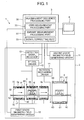
- FIG. 1 is a view illustrating a structure of a measurement device in accordance with the embodiment of the present invention
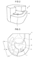
- FIG. 2 is a perspective view of a main unit of the measurement device illustrated in FIG. 1
- FIG. 3 is a plan view of the main unit.
- the measurement device 1 in accordance with the embodiment of the present invention measures an organism as an object, and includes a main unit 2 in which an organism as an object (a mouse M in the drawings) is put, and which measures the object, a control unit 3 controlling operation of each component of the main unit 2, and a display unit 4 displaying results of processing carried out by the control unit 3.
- the main unit 2 includes an apparatus 5 for generating a first external magnetic field having a low intensity, as means for generating a first magnetic field, an apparatus 6 for generating a second external magnetic field having a high intensity, as means for generating a second magnetic field, a cylindrical RF coil (a resonator) 7, and a turntable 8 rotating around a vertical axis, as rotating means.
- the turntable 8 is rotated by a mechanism 9 for rotating an object (see FIG. 3 ), including a motor, a pulley, and a belt and so on.
- the RF coil 7 is fixed on a periphery of the turntable 8. An organism as an object to be measured is kept in the RF coil 7, and is rotated together with the turntable 8 to thereby pass through magnetic fields in an order, generated by the first external magnetic-field generating apparatus 5 and the second external magnetic-field generating apparatus 6. In an example illustrated in FIG. 3 , the turntable 8 rotates in a clockwise direction.
- the RF coil 7 generates an electromagnetic radiation magnetic field in a direction perpendicular to static magnetic fields generated by the first external magnetic-field generating apparatus 5 and the second external magnetic-field generating apparatus 6.
- the first external magnetic-field generating apparatus 5 in the embodiment is comprised of three external magnetic-field generating apparatuses 5a, 5b and 5c, each of which includes an eternal magnet 50, a gradient magnetic field coil 51, and a magnetic field sweeping coil 52.
- the first external magnetic-field generating apparatus 5 provides an excited magnetic field for OMRI in a space in which the RF coil 7 fixed on the turntable 8 passes.
- the first external magnetic-field generating apparatus 5 excites electron spins of free radicals in an organism as an object kept in the RF coil 7 for carrying out OMRI measurement in the second external magnetic-field generating apparatus 6.
- the second external magnetic-field generating apparatus 6 includes an eternal magnet 60 for generating a static magnetic field in a space in which the RF coil 7 fixed on the turntable 8 passes, and further includes a gradient magnetic field coil 61 which generates gradient magnetic fields having a certain intensity at predetermined times in the static magnetic field generated by the eternal magnet 60, in accordance with a predetermined MR pulse sequence.
- the second external magnetic-field generating apparatus 6 provides an external magnetic field for carrying out MRI/OMRI. In the second external magnetic-field generating apparatus 6, MRI measurement and OMRI measurement are carried out.
- the first external magnetic-field generating apparatus 5 is electrically connected to the control unit 3 through a driver 10 which generates a first static magnetic field.
- the first static magnetic field generating driver 10 is electrically connected to an electric power source (not illustrated) for providing electric power to the gradient magnetic field coil 51 and the magnetic field sweeping coil 52.
- the first static magnetic field generating driver 10 controls the gradient magnetic field coil 51 and the magnetic field sweeping coil 52 in accordance with instructions received from the control unit 3.
- the first external magnetic-field generating apparatus 5 in the present embodiment generates a magnetic field having an intensity of 20 mT. It should be noted that the intensity may be varied such that it is greater than 0, but equal to or smaller than 50 mT in OMRI, and that it is greater than 0, but equal to or smaller than 11 mT in MRI.
- the eternal magnet 60 may be replaced with an electromagnet.
- the second external magnetic-field generating apparatus 6 is electrically connected to the control unit 3 through a driver 11 which generates a second static magnetic field.
- the second static magnetic field generating driver 11 is electrically connected to an electric power source (not illustrated) for providing electric power to the gradient magnetic field coil 61.
- the second static magnetic field generating driver 11 controls the gradient magnetic field coil 61 in accordance with instructions received from the control unit 3.
- the second external magnetic-field generating apparatus 6 in the present embodiment generates a magnetic field having an intensity of 1.5T. It should be noted that the intensity may be varied such that it is greater than 0, but equal to or smaller than 11T. It is more preferable for the magnetic field to have a greater intensity.
- the eternal magnet 60 which is capable of intensifying an intensity of the magnetic field up to about 2T.
- the eternal magnet 60 may be replaced with a superconducting magnet, in which case, an intensity of the magnetic field can be intensified up to about 11T.
- the RF coil 7 is electrically connected to the control unit 3 through a RF coil driver 12 or a detected signal receiver 13.
- the rotation mechanism 9 illustrated in FIG. 3 is electrically connected to the control unit 3 through a driver 14 which drives the rotation mechanism 9.
- the RF coil driver 12 and the driver 14 are electrically connected to an electric power source (not illustrated) for providing electric power to the RF coil 7 and the rotation mechanism 9.
- the RF coil driver 12 and the driver 14 drive the RF coil 7 and the rotation mechanism 9, respectively, in accordance with a sequence received from the control unit 3.
- the RF coil driver 12 drives the RF coil 7 in synchronization with the driver 10 at a timing at which the RF coil 7 rotating together with the turntable 8 passes magnetic fields generated by the first external magnetic field generating apparatus 5 and the second external magnetic field generating apparatus 6. Applying a high-frequency pulse to the RF coil 7, a high-frequency magnetic field is generated in the RF coil 7, and accordingly, the organism as an object put in the RF coil 7 is exposed to the high-frequency magnetic field.
- Electron spin resonance signals received at the RF coil 7 in the first external magnetic field generating apparatus 5 and magnetic resonance signals received at the RF coil 7 in the second external magnetic field generating apparatus 6 are transferred to the detected signal receiver 13, and then, transferred to the control unit 3. It is preferable that a period of time for driving the first external magnetic field generating apparatus 5 and then the second external magnetic field generating apparatus 6 is equal to or smaller than 1 second, and it is more preferable that the period of time is equal to or smaller than 0.7 seconds. In the present embodiment, the period of time is set equal to 0.5 seconds.
- the control unit 3 includes a measurement sequence processing part 30 for obtaining an electron spin resonance signal and a magnetic resonance signal of the organism as an object in accordance with a measurement sequence, a part 31 for processing OMRI measurement, a part 32 for processing MRI measurement, and a part 33 for correcting signals.
- the measurement sequence processing part 30 includes a sequence used for providing electric power to the first external magnetic field generating apparatus 5, the second external magnetic field generating apparatus 6, the RF coil 7, and the rotation mechanism 9, and a sequence for carrying out measurement in the RF coil 7.
- the measurement sequence processing part 30 controls the first external magnetic field generating apparatus 5, the second external magnetic field generating apparatus 6, the RF coil 7, and the rotation mechanism 9.
- the control unit 3 is actually comprised of a computer system, and executes a computer program stored in a recording medium such as a hard disc to thereby carry out the above-mentioned functions.
- the OMRI measurement processing part 31 and the MRI measurement processing part 32 process images in accordance with electron spin resonance signals and magnetic resonance signals obtained in accordance with the measurement sequence to thereby provide measured image signals.
- the signal correcting part 33 corrects image signals obtained through the OMRI measurement processing part 31 and the MRI measurement processing part 32 to thereby provide corrected image signals in which the influence caused by movement of the object is eliminated.
- the corrected image signals corrected by the signal correcting part 33 are displayed on the display unit 4.
- the OMRI measurement processing part 31 and the MRI measurement processing part 32 apply a gradient magnetic field in a moving direction "y" in which the organism as an object moves relative to the first and second external magnetic field generating apparatuses 5 and 6, and/or a direction "x" perpendicular to the moving direction "y” to thereby obtain image signals of the organism as an object by virtue of phase-encoding and/or frequency-encoding without a pause while the turntable 8 is rotating.
- a gradient magnetic field is applied in a direction "x" perpendicular to the moving direction "y” to thereby obtain image signals of the organism as an object by virtue of phase-encoding.
- frequency-encoding may be used in place of or together with phase-encoding.
- a direction in which a gradient magnetic field is applied may be changed into another direction.
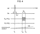
- FIG. 4 illustrates a measurement sequence in which a gradient magnetic field is applied in a direction "x" perpendicular to the moving direction "y” to thereby obtain image signals of the organism as an object by virtue of phase-encoding:
- a gradient magnetic field Gs is applied simultaneously (to) with application of a RF pulse, and then, a phase-encoding pulse Gp during t y0 to t y1 to obtain image signals.
- FIG. 5 is a typical view showing an intensity of a gradient magnetic field G y (n) of phase-encoding applied to the organism as an object in the case that the measurement is carried out in accordance with the measurement sequence illustrated in FIG. 4 .
- “v y " indicates a moving velocity of the organism in the moving direction "y”. Since the organism does move in the direction "x", "v x " is zero.
- the superscript (n) indicates that "G y " increases at every measurement (scan).
- each of "kx” and “ky” indicates a spatial frequency
- " ⁇ (x, y)" indicates a magnetization density.
- ⁇ indicates a gyromagnetic ratio
- ⁇ indicates a period of time.
- the equation (8) indicates that the movement of the organism as an object in a direction "y” is expressed as movement in a direction "y” in the measured images.
- An example of calculated lengths by which the object is shifted in the actually measured images is shown in Table 1. Parameters necessary for calculating the lengths are a moving velocity "v y " in a direction "y”, a period of time “ ⁇ t y " during which phase-encoding is applied, and a period of time "t y0 " until the phase-encoding starts being applied.
- shifting lengths (calculated lengths) calculated in accordance with the equation (8) are almost coincident with actually measured lengths. [Table 1] v y (m/s) shifting length (calculated) [mm] shifting length (experiment) [mm] 0.5 3.04 3.04 1.0 6.07 5.67 1.5 9.11 9.17 2.0 12.1 12.1
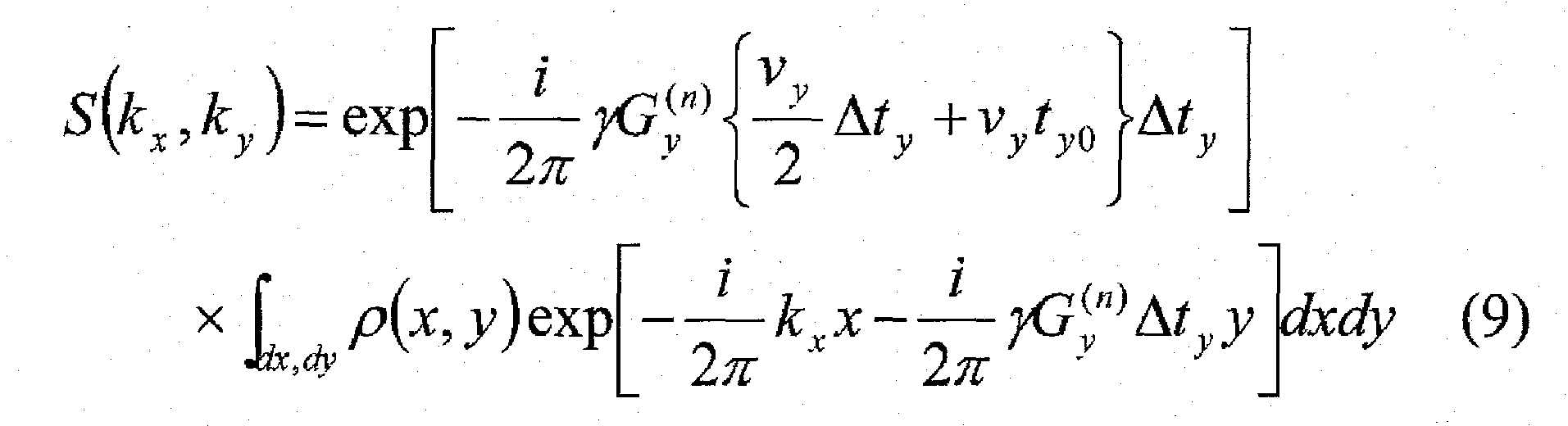
- the signal correcting part 33 calculates the corrected image signals S' (k x , k y ) in accordance with the equation (10), based on the measured image signals S (k x , k y ). This calculation corresponds to carrying out phase rotation.
- a small animal as an organism or an object for instance, a mouse M is put in the RF coil 7 fixed on the turntable 8.
- redox metabolism abnormality in oxidization stress disease in the organism, or brain functions in schizophrenia is analyzed with spatial images.
- the rotation mechanism 9 is driven to rotate the turntable 8 to cause the mouse M to pass through magnetic fields generated by the first external magnetic field generating apparatus 5 and the second external magnetic field generating apparatus 6 in this order.
- the first external magnetic field generating apparatus 5 irradiates high-frequency waves through the RF coil 7 and drives the magnetic field sweeping coil 52 to thereby swiftly sweep a static magnetic field.
- unpaired electron in the mouse M absorbs the high-frequency waves, and hence, electron spins are excited in resonance.
- the mouse M Having passed through the first external magnetic field generating apparatus 5, the mouse M enters the second external magnetic field generating apparatus 6, and thus, is put in a highly intensive static magnetic field having an intensity of 1T or greater, in the present embodiment, 1.5T. As a result, electron spins having been excited in resonance in the first external magnetic field generating apparatus 5 are transited in energy into nuclear spins. Then, signals generated from the mouse M as a result of the irradiation of high-frequency waves through the RF coil 7 are received at the detected signal receiver 13.
- the signals received at the detected signal receiver 13 in the above-mentioned manner are transferred to the control unit 3, and then, processed in the OMRI measurement processing part 31 and the MRI measurement processing part 32.
- the MRI measurement processing part 32 processes the signals having been obtained through the RF coil 7 in the second external magnetic field generating apparatus 5, to thereby synthesize MRI images.
- the OMRI measurement processing part 31 processes the signals having been obtained through the second external magnetic field generating apparatus 5 to thereby synthesize images showing nuclear spin distribution.
- the image signals obtained through the MRI measurement processing part 32 and the OMRI measurement processing part 31 are corrected by the above-mentioned signal correcting part 33, and the corrected image signals obtained by the signal correcting part 33 are displayed on the display unit 4.
- the MRI measurement processing part 32 and the OMRI measurement processing part 31 provide the image signals S (k x , k y ), and the image signals are corrected into the corrected image signals S' (k x , k y ) in which the influence caused by the "y" direction movement is eliminated.
- the first external magnetic field generating apparatus 5 and the second external magnetic field generating apparatus 6 may be designed to generate a magnetic field having an intensity different from each other, in which case, it is possible to rotate the turntable 8 together with the mouse M to cause the mouse M to pass successively through magnetic fields generated by the first and second external magnetic field generating apparatuses 5 and 6, to thereby obtain accurate non-shifted MRI images and OMRI images of the mouse M. Consequently, it is no longer necessary to reciprocatingly move the mouse M unlike the conventional process, and hence, it is possible to avoid the mouse from being loaded during moving and when stopped.
- the first external magnetic field generating apparatus 5 generating a magnetic field having a lower intensity is employed as an apparatus for exciting electron spin for carrying out OMRI
- the second external magnetic field generating apparatus 5 generating a magnetic field having a higher intensity is employed as an apparatus for generating an external magnetic field for carrying out MRI and OMRI. Accordingly, in the measurement device 1, since electron spin is excited by the first external magnetic field generating apparatus 5 generating a magnetic field having a lower intensity, and thereafter, OMRI measurement is carried out by the second external magnetic field generating apparatus 6 generating a magnetic field having a higher intensity, an external magnetic field used for carrying out OMRI has an extremely high intensity, and hence, it is possible to obtain accurate non-shifted OMRI images having high sensitivity and high resolution.
- the second external magnetic field generating apparatus 6 generating a magnetic field having a higher intensity may be employed as an apparatus for generating an external magnetic field for carrying out MRI
- the first external magnetic field generating apparatus generating a magnetic field having a lower intensity may be employed as an apparatus for generating an external magnetic field for carrying out OMRI.
- the second external magnetic field generating apparatus 6 provides MRI images
- the first external magnetic field generating apparatus 5 provides OMRI images.
- the measurement device 1 in accordance with the present embodiment is designed to rotate the mouse M by means of the turntable 8.
- the first and second external magnetic field generating apparatuses 5 and 6 may be designed to rotate without rotating the mouse M, in which case, the mouse M may be caused to make reciprocating movement. Since the moving direction "y" of the mouse M relative to the first and second external magnetic field generating apparatuses 5 and 6 is kept unchanged, it is possible to correct the image signals through the signal correcting part 33 in accordance with the above-mentioned way.
- the measurement device 1 in accordance with the present embodiment is designed to include the two external external magnetic field generating apparatuses used for carrying out MRI/OMRI measurement, but may be designed to include two or more external external magnetic field generating apparatuses which generate magnetic fields each having an intensity different from one another, and through which the organism as an object is caused to move.
- the signal correcting part 33 in the measurement device 1 in accordance with the present embodiment may be designed to correct the image signals even when the organism as an object is caused to move within a single external magnetic field generating apparatus.
- various measuring devices such as an X-ray CT (Computed Tomography) apparatus, a supersonic-wave visualizing apparatus and a positron emission tomography (PET) apparatus may be arranged on a path on which the organism as an object situated on the turntable 8 is rotated, to thereby successively make a plurality of measurements.
- X-ray CT Computed Tomography
- PET positron emission tomography
- the measurement device 1 can provide structural images as morphologic images as well as redox dynamics images as functional images of an organism.
- the measurement device can provide morphologic images of a material other than an organism, for instance, a structure and/or a defect of semiconductor.
- the measurement device can provide images of an object, such as functional images and morphologic images, by virtue of various resonances such as electron spin resonance and nuclear magnetic resonance.
- the signal correcting part 33 in the measurement device 1 in accordance with the present embodiment is designed to correct two-dimensional images such as MRI/OMRI images. It should be noted that the correction process carried out in the signal correcting part 33 may be applied to three- or more-dimensional images.
- FIG. 6 illustrates a measurement sequence in which a gradient magnetic field is applied in directions "x" and "z" both perpendicular to the moving direction "y” to thereby obtain image signals of the organism as an object by virtue of phase-encoding.
- a gradient magnetic field Gs is applied simultaneously with application of a RF pulse (to), and then, phase-encoding pulses Gp and Gp 2 during t y0 to t y1 to obtain image signals.
- FIG. 7 is a typical view showing an intensity of a gradient magnetic field G y (n) of phase-encoding applied to the organism as an object in the case that the measurement is carried out in accordance with the measurement sequence.
- "v y " indicates a moving velocity of the organism in the moving direction "y”.
- y ⁇ y + v y 2 ⁇ ⁇ ⁇ t y + v y ⁇ t y ⁇ 0
- the measurement device and the measurement method both in accordance with the present invention are useful as an apparatus and a method for obtaining images of an object by virtue of various magnetic resonances such as electron spin resonance and nuclear magnetic resonance.
- the present invention preferably provides accurate images in which the influence exerted by a moving velocity of a moving object is eliminated, in a measurement device and a measurement method for obtaining images of an object, such as functional images and morphologic images, by virtue of magnetic resonance.
Landscapes
- Physics & Mathematics (AREA)
- Health & Medical Sciences (AREA)
- Nuclear Medicine, Radiotherapy & Molecular Imaging (AREA)
- High Energy & Nuclear Physics (AREA)
- Radiology & Medical Imaging (AREA)
- General Physics & Mathematics (AREA)
- Condensed Matter Physics & Semiconductors (AREA)
- Engineering & Computer Science (AREA)
- General Health & Medical Sciences (AREA)
- Life Sciences & Earth Sciences (AREA)
- Signal Processing (AREA)
- Molecular Biology (AREA)
- Vascular Medicine (AREA)
- Surgery (AREA)
- Animal Behavior & Ethology (AREA)
- Heart & Thoracic Surgery (AREA)
- Public Health (AREA)
- Veterinary Medicine (AREA)
- Medical Informatics (AREA)
- Biomedical Technology (AREA)
- Pathology (AREA)
- Biophysics (AREA)
- Pulmonology (AREA)
- Theoretical Computer Science (AREA)
- Magnetic Resonance Imaging Apparatus (AREA)
Abstract
Description
- The invention relates to a measurement device and a measurement method for obtaining images of an object, such as functional images and morphologic images, by virtue of various magnetic resonances such as electron spin resonance (ESR) and nuclear magnetic resonance (NMR).
- Redox metabolism containing active oxygen and free radicals is much concerned with a lot of physiological phenomena, and causes and development of diseases. Accordingly, if redox dynamics in a laboratory animal could be visualized at an individual level, it would be possible without doubt to contribute to elucidation of life phenomenon, analysis of diseases, establishment of curing diseases, and development of medicines.
- Electron spin resonance imaging (ESRI), in accordance with which free radicals as intermediate products of redox metabolism are peculiarly detected, is useful for visualizing redox dynamics. However, images resulted from ESRI lack correspondence with internal organs. In order to solve this problem, there has been developed an ESRI-MRI combination type apparatus for analyzing magnetic resonance images, in which images resulted from ESRI are superimposed with MRI images of internal organs obtained by nuclear magnetic resonance imaging (MRI).
- Overhauser effect is a phenomenon in which electron spin of free radicals is made to be ESR-transited to thereby cause nuclear spin to be polarized by virtue of dipole-dipole interaction between electron spin and nuclear spin. OMRI is an imaging process in which after electron spin of free radicals is excited, hydrogen nuclear spin of water molecule is polarized for carrying out MRI measurement. In OMRI, nuclear spin polarization is 330-times intensified at maximum (theoretical value) in comparison with Boltzmann distribution of usual nuclear spin. That is, OMRI makes it possible to realize 330-times sensitization (theoretical value) in comparison with usual MRI measurement.
- The inventors of the present application suggested, in the
patent reference 1, the measurement device for obtaining images of organism structures by virtue of various magnetic resonances such as electron spin resonance and nuclear magnetic resonance. The measurement device is designed to include means for generating a first magnetic field having a certain intensity, means for generating a second magnetic field having an intensity greater than the intensity of the first magnetic field, means for linearly moving an object between the first magnetic field generating means and the second magnetic field generating means in synchronization with irradiation of RF pulses onto the object, and means for stopping the object to move, and obtaining images of organism structure of the object in accordance with signals detected in response to the RF pulses. - In the above-mentioned measurement device, the means for generating a first magnetic field may be employed as both an apparatus for generating an external magnetic field for ESRI and an apparatus for exciting electron spin for PEDRI (OMRI), and the means for generating a second magnetic field may be employed as an apparatus for generating an external magnetic field for MRI and OMRI. Thus, images of an amount of radicals varying with the lapse of time are obtained by OMRI, and images of radicals varying in quality are obtained by spectrum/spatial four-dimensional ESRI/MRI, and further, a magnetic field generated by the means for generating a second magnetic field can be designed to have a high intensity, resulting in that it is possible to obtain images having high sensitivity and high resolution.
-
- Patent Reference 1: Japanese Patent Application Publication No.
2006-204551 - In the above-mentioned measurement device, the means for linearly moving an object, disposed between the first magnetic field generating means and the second magnetic field generating means, causes the object to reciprocatingly move, and after the object is caused to stop, the measurement is carried out. Thus, high acceleration is applied to the object when the object starts moving and is stopped. Consequently, the above-mentioned measurement device is accompanied with a problem that high load is unavoidably applied to the organism as the object while moving.
- Thus, the inventors are presently developing a measurement device which is able to measure an object moving between a plurality of magnetic field generating means, without stopping the object to thereby avoid the object from being loaded. However, measuring an object without stopping the object, there newly arises a problem that images of the object are influenced by a moving velocity, and resultingly, images of the object are shifted.
- In view of the above-mentioned problems, it is an object of the present invention to provide a measurement device and a measurement method for obtaining images of an object to be measured such as functional images and morphologic images by virtue of magnetic resonance, both of which are capable of providing accurate images by eliminating influences caused by a moving velocity to a moving object.
- A measurement device for obtaining images of an object to be measured by virtue of magnetic resonance, in accordance with the present invention, includes magnetic-field generating means for generating a magnetic field to excite magnetic resonance of the object, moving means for moving one of the object and the magnetic-field generating means to thereby move the object in a magnetic field generated by the magnetic-field generating means, measurement means for applying a gradient magnetic field in at least one of a moving direction "y" in which the object moves relative to the magnetic-field generating means, and a direction "x" perpendicular to the moving direction "y" to thereby obtain image signals of the object by virtue of at least one of phase-encoding and frequency-encoding without stopping the object or the magnetic-field generating means while they are being moved by the moving means, and correction means for eliminating influence on the image signals derived from movement of the object in the moving direction "y" to provide corrected image signals.
- A measurement method for obtaining images of an object to be measured by virtue of magnetic resonance, in accordance with the present invention, includes moving one of the object and magnetic-field generating means which generates a magnetic field to excite magnetic resonance of the object to thereby move the object through a magnetic field generated by the magnetic-field generating means, applying a gradient magnetic field in at least one of a moving direction "y" in which the object moves relative to the magnetic-field generating means, and a direction "x" perpendicular to the moving direction "y" to thereby obtain image signals of the object by virtue of at least one of phase-encoding and frequency-encoding without stopping the object or the magnetic-field generating means while they are being moved, and eliminating influence on the image signals derived from movement of the object in the moving direction "y" to provide corrected image signals.
- In accordance with the above-mentioned invention, even if the object to be measured or the magnetic field generating means were moving by the moving means, it would be possible to obtain corrected image signals in which the influence on the image signals derived from movement of the object relative to the magnetic field generating means in the moving direction "y" is eliminated, ensuring it possible to provide accurate non-shifted images of the object, such as functional images and morphologic images.
- It is preferable that the corrected image signals are obtained in accordance with the following equation:

S (kx, ky) indicates the image signals,
S'(kx, ky) indicates the corrected image signals,
each of kx and ky indicates a spatial frequency in the directions "x" and "y" respectively,
"y "indicates a gyromagnetic ratio,
"Gy (n)" indicates an intensity of a gradient magnetic field of the phase-encoding or the frequency-encoding in n-th measurement,
"vy" indicates a moving velocity in the moving direction "y",
"Δty" indicates a period of time during which the phase-encoding or the frequency-encoding is applied, and
"ty0" indicates a period of time until the phase-encoding or the frequency-encoding starts being applied. - Thus, it is possible to obtain the corrected image signals S' (kx, ky) in which the influence on the image signals derived from movement of the object in the moving direction "y", caused by a moving velocity in the moving direction "y", a period of time during which the phase-encoding or the frequency-encoding is applied, and/or a period of time until the phase-encoding or the frequency-encoding starts being applied, is eliminated, ensuring it possible to obtain accurate non-shifted images of the object, such as functional images and morphologic images, in particular, accurate two-dimensional images.
- It is preferable that the corrected image signals are obtained in accordance with the following equation:

S (kx, ky, kz) indicates the image signals,
S' (kx, ky, kz) indicates the corrected image signals,
each of kx, ky and kz indicates a spatial frequency in the direction "x", the direction "y", and a direction "z", respectively,
"γ " indicates a gyromagnetic ratio,
"Gy (n)" indicates an intensity of a gradient magnetic field of the phase-encoding or the frequency-encoding in n-th measurement,
"vy" indicates a moving velocity in the moving direction "y",
"Δty" indicates a period of time during which the phase-encoding or the frequency-encoding is applied, and
"ty0" indicates a period of time until the phase-encoding or the frequency-encoding starts being applied. - Thus, it is possible to obtain the corrected image signals S' (kx, ky, kz) in which the influence on the image signals derived from movement of the object in the moving direction "y", caused by a moving velocity in the moving direction "y", a period of time during which the phase-encoding or the frequency-encoding is applied, and/or a period of time until the phase-encoding or the frequency-encoding starts being applied, is eliminated, ensuring it possible to obtain accurate non-shifted images of the object, such as functional images and morphologic images, in particular, accurate three-dimensional images.
- It is preferable that the magnetic-field generating means includes means for generating a first magnetic field having a predetermined intensity, and means for generating a second magnetic field having an intensity different from the intensity of the first magnetic-field generating means, and that the moving means moves one of the object, the first magnetic-field generating means, and the second magnetic-field generating means to thereby move the object through magnetic fields generated by the first magnetic-field generating means and the second magnetic-field generating means in this order.
- Thus, it is possible to obtain accurate non-shifted images of the object, such as functional images and morphologic images, by virtue of various magnetic resonances such as electron spin resonance and nuclear magnetic resonance, by causing a plurality of magnetic field generating means to generate magnetic fields having intensities different from one another, and causing the object to pass in succession through the magnetic fields generated by the plurality of magnetic field generating means.
- It is preferable that the moving means comprises rotating means which rotates one of the object and the first and second magnetic-field generating means to thereby move the object through magnetic fields generated by the first magnetic-field generating means and the second magnetic-field generating means in this order.
- Thus, it is possible to obtain accurate non-shifted images of the object, such as functional images and morphologic images, by virtue of various magnetic resonances such as electron spin resonance and nuclear magnetic resonance, by causing the object or the first and second magnetic field generating means to rotate, and causing the object to pass in succession through the magnetic fields generated by the plurality of magnetic field generating means.
- As an object to be measured in the present invention, there may be selected a body of a living (organism) or a material other than a living (for instance, semiconductor). When a living is selected as an object, there can be obtained accurate non-shifted images, such as redox dynamics images as functional images, organism functional image including metabolism images, and structural images (for instance, 13C, 1H, 31P nuclei) as morphologic images. When a material is selected as an object, there can be obtained accurate images such as morphologic images of structures and defects, and distribution images of a compound.
- It is preferable that one of the first and second magnetic-field generating means excites nuclear magnetic resonance for measurement, and the other excites electron spin resonance for measurement, for instance, in order to obtain images of redox dynamics. Thus, it is possible to obtain accurate non-shifted images of redox dynamics of organism by virtue of OMR1.
- Any one of the first and second magnetic-field generating means may generate a magnetic field having a higher intensity than the other. If the second magnetic-field generating means is designed to generate a magnetic field having an intensity higher than the same generated by the first magnetic-field generating means, the first magnetic-field generating means generating a magnetic field having a lower intensity may be employed as an apparatus for exciting electron spin for carrying out OMRI, and the second magnetic-field generating means generating a magnetic field having a higher intensity may be employed as an apparatus for generating an external magnetic field for carrying out MRI and OMRI. Thus, the second magnetic-field generating means provides MRI images and OMRI images. In particular, in the measurement device in accordance with the present invention, since electron spin is excited by the first magnetic-field generating means generating a magnetic field having a lower intensity, and thereafter, OMRI measurement is carried out by the second magnetic-field generating means generating a magnetic field having a higher intensity, an external magnetic field used for carrying out OMRI has an extremely high intensity, and hence, it is possible to obtain accurate non-shifted OMRI images having high sensitivity and high resolution.
- On the other hand, if the first magnetic-field generating means is designed to generate a magnetic field having an intensity higher than the same generated by the second magnetic-field generating means, the first magnetic-field generating means generating a magnetic field having a higher intensity may be employed as an apparatus for generating an external magnetic field for carrying out MRI, and the second magnetic-field generating means generating a magnetic field having a lower intensity may be employed as an apparatus for generating an external magnetic field for carrying out OMRI. Thus, the first magnetic-field generating means provides MRI images, and the second magnetic-field generating means provides OMRI images.
- As mentioned above, since the first or second magnetic field generating means excites magnetic resonance for measuring an object in the measurement device in accordance with the present embodiment, it is possible to obtain accurate non-shifted images of an object such as functional images and morphologic images, by virtue of various magnetic resonances such as electron spin resonance and nuclear magnetic resonance.
-
- (1) In accordance with the present invention, by moving an object or magnetic field generating means which generates a magnetic field for exciting a magnetic resonance of the object, the object is caused to move through a magnetic field generated by the magnetic field generating means, and further by applying a gradient magnetic field in a moving direction "y" in which the object moves relative to the magnetic-field generating means or in a direction "x" perpendicular to the moving direction "y" to thereby obtain image signals of the object by virtue of phase-encoding and/or frequency-encoding without stopping the object or the magnetic-field generating means while they are being moved. Eliminating the influence onto the image signals caused by the movement in the direction "y" out of the thus obtained image signals, corrected image signals can be obtained. Thus, even if the object to be measured or the magnetic field generating means were moving by the moving means, it would be possible to obtain accurate non-shifted images of the object, such as functional images and morphologic images, in which the influence caused by a moving velocity of the moving object is eliminated.
-
- (2) By obtaining the corrected image signals in accordance with the following equation:

-
- (3) By obtaining the corrected image signals in accordance with the following equation:

-
- (4) By designing the magnetic-field generating means to include means for generating a first magnetic field having a predetermined intensity, and means for generating a second magnetic field having an intensity different from the intensity of the first magnetic-field generating means, and further by designing the moving means to move the object or the first and second magnetic-field generating means to thereby move the object through magnetic fields generated by the first and second magnetic-field generating means in this order, it is possible to obtain, without stopping the object to move, accurate non-shifted images of the object, such as functional images and morphologic images, by virtue of various magnetic resonances such as electron spin resonance and nuclear magnetic resonance.
-
- (5) By designing the moving means to comprise rotating means which rotates one of the object and the first and second magnetic-field generating means to thereby move the object through magnetic fields generated by the first magnetic-field generating means and the second magnetic-field generating means in this order, it is no longer necessary to reciprocatingly move the object, and it is possible to obtain accurate non-shifted images of the object, such as functional images and morphologic images, by virtue of various magnetic resonances such as electron spin resonance and nuclear magnetic resonance, without stopping the object or the first and second magnetic-field generating means and further with the object being moved in rotation. Thus, it is possible to eliminate a load exerted on the object, caused when the object is temporarily stopped in reciprocal movement during measurement carried out in a conventional manner, and further, possible to avoid the first and second magnetic-field generating means from being loaded when they are caused to stop.
-
- (6) By designing one of the first and second magnetic-field generating means to excite nuclear magnetic resonance, and the other to excite electron spin resonance, it is possible to obtain accurate non-shifted redox dynamics images of organism by virtue of OMRI.
-
- (7) If the second magnetic-field generating means is designed to generate a magnetic field having an intensity higher than the same generated by the first magnetic-field generating means, the first magnetic-field generating means generating a magnetic field having a lower intensity may be employed as an apparatus for exciting electron spin for carrying out OMRI, and the second magnetic-field generating means generating a magnetic field having a higher intensity may be employed as an apparatus for generating an external magnetic field for carrying out MRI and OMRI. Thus, an external magnetic field used for carrying out OMRI has an extremely high intensity, and hence, it is possible to obtain accurate non-shifted OMRI images having high sensitivity and high resolution.
-
- (8) If the first magnetic-field generating means is designed to generate a magnetic field having an intensity higher than the same generated by the second magnetic-field generating means, the first magnetic-field generating means generating a magnetic field having a higher intensity may be employed as an apparatus for generating an external magnetic field for carrying out MRI, and the second magnetic-field generating means generating a magnetic field having a lower intensity may be employed as an apparatus for generating an external magnetic field for carrying out OMRI. Thus, it is possible to obtain accurate non-shifted OMRI images having high sensitivity.
-
- [
FIG. 1] FIG. 1 is a view illustrating a structure of the measurement device in accordance with the embodiment of the present invention. - [
FIG. 2] FIG. 2 is a perspective view of a main unit of the measurement device illustrated inFIG. 1 . - [
FIG. 3] FIG. 3 is a plan view of a main unit of the measurement device illustrated inFIG. 1 . - [
FIG. 4] FIG. 4 shows an example of the measurement sequence. - [
FIG. 5] FIG. 5 is a typical view showing an intensity of a gradient magnetic field Gy (n) of phase-encoding applied to an organism as an object in the case that the measurement is carried out in accordance with the measurement sequence illustrated inFIG. 4 . - [
FIG. 6] FIG. 6 shows another example of the measurement sequence. - [
FIG. 7] FIG. 7 is a typical view showing an intensity of a gradient magnetic field Gy (n) obtained when phase-encoding is applied to an organism as an object in the case that the measurement is carried out in accordance with the measurement sequence illustrated inFIG. 6 . -
- 1
- Measurement device
- 2
- Main unit
- 3
- Control unit
- 4
- Display unit
- 5, 6
- Apparatus for generating an external magnetic field
- 7
- RF coil
- 8
- Turntable
- 9
- Mechanism for rotating an object
- 10, 11
- Driver for generating a static magnetic field
- 12
- RF coil driver
- 13
- Detected signal receiver
- 14
- Driver for driving the mechanism for rotating an object
- 30
- Part for processing a measurement sequence
- 31
- Part for processing OMRI measurement
- 32
- Part for processing MRI measurement
- 33
- Part for correcting signals
-
FIG. 1 is a view illustrating a structure of a measurement device in accordance with the embodiment of the present invention,FIG. 2 is a perspective view of a main unit of the measurement device illustrated inFIG. 1 , andFIG. 3 is a plan view of the main unit.
With reference toFIG. 1 , themeasurement device 1 in accordance with the embodiment of the present invention measures an organism as an object, and includes amain unit 2 in which an organism as an object (a mouse M in the drawings) is put, and which measures the object, acontrol unit 3 controlling operation of each component of themain unit 2, and adisplay unit 4 displaying results of processing carried out by thecontrol unit 3. - The
main unit 2 includes anapparatus 5 for generating a first external magnetic field having a low intensity, as means for generating a first magnetic field, anapparatus 6 for generating a second external magnetic field having a high intensity, as means for generating a second magnetic field, a cylindrical RF coil (a resonator) 7, and aturntable 8 rotating around a vertical axis, as rotating means. Theturntable 8 is rotated by amechanism 9 for rotating an object (seeFIG. 3 ), including a motor, a pulley, and a belt and so on. - The
RF coil 7 is fixed on a periphery of theturntable 8. An organism as an object to be measured is kept in theRF coil 7, and is rotated together with theturntable 8 to thereby pass through magnetic fields in an order, generated by the first external magnetic-field generating apparatus 5 and the second external magnetic-field generating apparatus 6. In an example illustrated inFIG. 3 , theturntable 8 rotates in a clockwise direction. TheRF coil 7 generates an electromagnetic radiation magnetic field in a direction perpendicular to static magnetic fields generated by the first external magnetic-field generating apparatus 5 and the second external magnetic-field generating apparatus 6. - The first external magnetic-
field generating apparatus 5 in the embodiment is comprised of three external magnetic-field generating apparatuses eternal magnet 50, a gradientmagnetic field coil 51, and a magneticfield sweeping coil 52. The first external magnetic-field generating apparatus 5 provides an excited magnetic field for OMRI in a space in which theRF coil 7 fixed on theturntable 8 passes. The first external magnetic-field generating apparatus 5 excites electron spins of free radicals in an organism as an object kept in theRF coil 7 for carrying out OMRI measurement in the second external magnetic-field generating apparatus 6. - The second external magnetic-
field generating apparatus 6 includes aneternal magnet 60 for generating a static magnetic field in a space in which theRF coil 7 fixed on theturntable 8 passes, and further includes a gradientmagnetic field coil 61 which generates gradient magnetic fields having a certain intensity at predetermined times in the static magnetic field generated by theeternal magnet 60, in accordance with a predetermined MR pulse sequence. The second external magnetic-field generating apparatus 6 provides an external magnetic field for carrying out MRI/OMRI. In the second external magnetic-field generating apparatus 6, MRI measurement and OMRI measurement are carried out. - The first external magnetic-
field generating apparatus 5 is electrically connected to thecontrol unit 3 through adriver 10 which generates a first static magnetic field. The first static magneticfield generating driver 10 is electrically connected to an electric power source (not illustrated) for providing electric power to the gradientmagnetic field coil 51 and the magneticfield sweeping coil 52. The first static magneticfield generating driver 10 controls the gradientmagnetic field coil 51 and the magneticfield sweeping coil 52 in accordance with instructions received from thecontrol unit 3. The first external magnetic-field generating apparatus 5 in the present embodiment generates a magnetic field having an intensity of 20 mT. It should be noted that the intensity may be varied such that it is greater than 0, but equal to or smaller than 50 mT in OMRI, and that it is greater than 0, but equal to or smaller than 11 mT in MRI. Furthermore, theeternal magnet 60 may be replaced with an electromagnet. - The second external magnetic-
field generating apparatus 6 is electrically connected to thecontrol unit 3 through adriver 11 which generates a second static magnetic field. The second static magneticfield generating driver 11 is electrically connected to an electric power source (not illustrated) for providing electric power to the gradientmagnetic field coil 61. The second static magneticfield generating driver 11 controls the gradientmagnetic field coil 61 in accordance with instructions received from thecontrol unit 3. The second external magnetic-field generating apparatus 6 in the present embodiment generates a magnetic field having an intensity of 1.5T. It should be noted that the intensity may be varied such that it is greater than 0, but equal to or smaller than 11T. It is more preferable for the magnetic field to have a greater intensity. In the present embodiment, there is used theeternal magnet 60, which is capable of intensifying an intensity of the magnetic field up to about 2T. As an alternative, theeternal magnet 60 may be replaced with a superconducting magnet, in which case, an intensity of the magnetic field can be intensified up to about 11T. - The
RF coil 7 is electrically connected to thecontrol unit 3 through aRF coil driver 12 or a detectedsignal receiver 13. Therotation mechanism 9 illustrated inFIG. 3 is electrically connected to thecontrol unit 3 through adriver 14 which drives therotation mechanism 9. TheRF coil driver 12 and thedriver 14 are electrically connected to an electric power source (not illustrated) for providing electric power to theRF coil 7 and therotation mechanism 9. - The
RF coil driver 12 and thedriver 14 drive theRF coil 7 and therotation mechanism 9, respectively, in accordance with a sequence received from thecontrol unit 3. TheRF coil driver 12 drives theRF coil 7 in synchronization with thedriver 10 at a timing at which theRF coil 7 rotating together with theturntable 8 passes magnetic fields generated by the first external magneticfield generating apparatus 5 and the second external magneticfield generating apparatus 6. Applying a high-frequency pulse to theRF coil 7, a high-frequency magnetic field is generated in theRF coil 7, and accordingly, the organism as an object put in theRF coil 7 is exposed to the high-frequency magnetic field. - Electron spin resonance signals received at the
RF coil 7 in the first external magneticfield generating apparatus 5 and magnetic resonance signals received at theRF coil 7 in the second external magneticfield generating apparatus 6 are transferred to the detectedsignal receiver 13, and then, transferred to thecontrol unit 3. It is preferable that a period of time for driving the first external magneticfield generating apparatus 5 and then the second external magneticfield generating apparatus 6 is equal to or smaller than 1 second, and it is more preferable that the period of time is equal to or smaller than 0.7 seconds. In the present embodiment, the period of time is set equal to 0.5 seconds. - The
control unit 3 includes a measurementsequence processing part 30 for obtaining an electron spin resonance signal and a magnetic resonance signal of the organism as an object in accordance with a measurement sequence, apart 31 for processing OMRI measurement, apart 32 for processing MRI measurement, and apart 33 for correcting signals. The measurementsequence processing part 30 includes a sequence used for providing electric power to the first external magneticfield generating apparatus 5, the second external magneticfield generating apparatus 6, theRF coil 7, and therotation mechanism 9, and a sequence for carrying out measurement in theRF coil 7. The measurementsequence processing part 30 controls the first external magneticfield generating apparatus 5, the second external magneticfield generating apparatus 6, theRF coil 7, and therotation mechanism 9. Thecontrol unit 3 is actually comprised of a computer system, and executes a computer program stored in a recording medium such as a hard disc to thereby carry out the above-mentioned functions. - The OMRI
measurement processing part 31 and the MRImeasurement processing part 32 process images in accordance with electron spin resonance signals and magnetic resonance signals obtained in accordance with the measurement sequence to thereby provide measured image signals. Thesignal correcting part 33 corrects image signals obtained through the OMRImeasurement processing part 31 and the MRImeasurement processing part 32 to thereby provide corrected image signals in which the influence caused by movement of the object is eliminated. The corrected image signals corrected by thesignal correcting part 33 are displayed on thedisplay unit 4. - Hereinbelow is explained in detail the process of correcting the image signals, carried out by the
signal correcting part 33.
The OMRImeasurement processing part 31 and the MRImeasurement processing part 32 apply a gradient magnetic field in a moving direction "y" in which the organism as an object moves relative to the first and second external magneticfield generating apparatuses turntable 8 is rotating. - Hereinbelow is explained a case, for simplification, that a gradient magnetic field is applied in a direction "x" perpendicular to the moving direction "y" to thereby obtain image signals of the organism as an object by virtue of phase-encoding. However, it should be noted that frequency-encoding may be used in place of or together with phase-encoding. A direction in which a gradient magnetic field is applied may be changed into another direction.
-
FIG. 4 illustrates a measurement sequence in which a gradient magnetic field is applied in a direction "x" perpendicular to the moving direction "y" to thereby obtain image signals of the organism as an object by virtue of phase-encoding: As illustrated inFIG. 4 , in the measurement sequence, a gradient magnetic field Gs is applied simultaneously (to) with application of a RF pulse, and then, a phase-encoding pulse Gp during ty0 to ty1 to obtain image signals.FIG. 5 is a typical view showing an intensity of a gradient magnetic field Gy (n) of phase-encoding applied to the organism as an object in the case that the measurement is carried out in accordance with the measurement sequence illustrated inFIG. 4 . "vy" indicates a moving velocity of the organism in the moving direction "y". Since the organism does move in the direction "x", "vx" is zero. The superscript (n) indicates that "Gy" increases at every measurement (scan). - The magnetized signal S(kx, ky) encoded by the gradient magnetic field is expressed as follows:

- A location of the organism as an object while moving is expressed as follows:


- Since the object moves only in the "y" direction, and the gradient magnetic field Gy (n) is applied only during ty0 to ty1, the above-mentioned equation (2-2) is expressed as follows:

- Thus, the above-mentioned equation (1) is expressed as follows:

- Herein, introducing "y' " defined with the equation (4), there is carried out coordinate transformation.

- By carrying out the coordinate transformation, "y" is expressed with the equation (5).

- Carrying out coordinate transformation by introducing the equation (5) into the equation (3), there is obtained the equation (6).

- By carrying out Fourier transformation, the equation (6) is expressed as follows:


- The equation (8) indicates that the movement of the organism as an object in a direction "y" is expressed as movement in a direction "y" in the measured images. An example of calculated lengths by which the object is shifted in the actually measured images is shown in Table 1. Parameters necessary for calculating the lengths are a moving velocity "vy" in a direction "y", a period of time "Δty" during which phase-encoding is applied, and a period of time "ty0" until the phase-encoding starts being applied. As is understood in Table 1, shifting lengths (calculated lengths) calculated in accordance with the equation (8) are almost coincident with actually measured lengths.
[Table 1] vy (m/s) shifting length (calculated) [mm] shifting length (experiment) [mm] 0.5 3.04 3.04 1.0 6.07 5.67 1.5 9.11 9.17 2.0 12.1 12.1 - Then, when the influence caused by the movement in the direction "y" is eliminated, since the equation (3) can be rewritten into the equation (9), the corrected image signal is expressed as shown in the equation (10).

- The
signal correcting part 33 calculates the corrected image signals S' (kx, ky) in accordance with the equation (10), based on the measured image signals S (kx, ky). This calculation corresponds to carrying out phase rotation. - By applying Fourier transformation to the corrected image signals S' (kx, ky), there is obtained the equation (11).

- Hereinbelow is explained the operation of the
measurement device 1 having the above-mentioned structure.
First, a small animal as an organism or an object, for instance, a mouse M is put in theRF coil 7 fixed on theturntable 8. In the present embodiment, redox metabolism abnormality in oxidization stress disease in the organism, or brain functions in schizophrenia is analyzed with spatial images. - Then, the
rotation mechanism 9 is driven to rotate theturntable 8 to cause the mouse M to pass through magnetic fields generated by the first external magneticfield generating apparatus 5 and the second external magneticfield generating apparatus 6 in this order. The first external magneticfield generating apparatus 5 irradiates high-frequency waves through theRF coil 7 and drives the magneticfield sweeping coil 52 to thereby swiftly sweep a static magnetic field. Thus, unpaired electron in the mouse M absorbs the high-frequency waves, and hence, electron spins are excited in resonance. - Having passed through the first external magnetic
field generating apparatus 5, the mouse M enters the second external magneticfield generating apparatus 6, and thus, is put in a highly intensive static magnetic field having an intensity of 1T or greater, in the present embodiment, 1.5T. As a result, electron spins having been excited in resonance in the first external magneticfield generating apparatus 5 are transited in energy into nuclear spins. Then, signals generated from the mouse M as a result of the irradiation of high-frequency waves through theRF coil 7 are received at the detectedsignal receiver 13. - The signals received at the detected
signal receiver 13 in the above-mentioned manner are transferred to thecontrol unit 3, and then, processed in the OMRImeasurement processing part 31 and the MRImeasurement processing part 32. The MRImeasurement processing part 32 processes the signals having been obtained through theRF coil 7 in the second external magneticfield generating apparatus 5, to thereby synthesize MRI images. The OMRImeasurement processing part 31 processes the signals having been obtained through the second external magneticfield generating apparatus 5 to thereby synthesize images showing nuclear spin distribution. - The image signals obtained through the MRI
measurement processing part 32 and the OMRImeasurement processing part 31 are corrected by the above-mentionedsignal correcting part 33, and the corrected image signals obtained by thesignal correcting part 33 are displayed on thedisplay unit 4. - As mentioned above, in the
measurement device 1 in accordance with the present embodiment, the MRImeasurement processing part 32 and the OMRImeasurement processing part 31 provide the image signals S (kx, ky), and the image signals are corrected into the corrected image signals S' (kx, ky) in which the influence caused by the "y" direction movement is eliminated. Hence, even if the mouse M were moving by theturntable 8, it is possible to obtain accurate non-shifted MRI images and OMRI images of the mouse M in which the influence caused by the moving velocity of the moving mouse M is eliminated. - In the
measurement device 1 in accordance with the present embodiment, the first external magneticfield generating apparatus 5 and the second external magneticfield generating apparatus 6 may be designed to generate a magnetic field having an intensity different from each other, in which case, it is possible to rotate theturntable 8 together with the mouse M to cause the mouse M to pass successively through magnetic fields generated by the first and second external magneticfield generating apparatuses - In the
measurement device 1, the first external magneticfield generating apparatus 5 generating a magnetic field having a lower intensity is employed as an apparatus for exciting electron spin for carrying out OMRI, and the second external magneticfield generating apparatus 5 generating a magnetic field having a higher intensity is employed as an apparatus for generating an external magnetic field for carrying out MRI and OMRI. Accordingly, in themeasurement device 1, since electron spin is excited by the first external magneticfield generating apparatus 5 generating a magnetic field having a lower intensity, and thereafter, OMRI measurement is carried out by the second external magneticfield generating apparatus 6 generating a magnetic field having a higher intensity, an external magnetic field used for carrying out OMRI has an extremely high intensity, and hence, it is possible to obtain accurate non-shifted OMRI images having high sensitivity and high resolution. - In the
measurement device 1, it is possible to carry out the measurement by rotating theturntable 8 in a reverse direction to thereby cause the mouse M to pass through the second external magneticfield generating apparatus 6 and the first external magneticfield generating apparatus 5 in this order, in which case, the second external magneticfield generating apparatus 6 generating a magnetic field having a higher intensity may be employed as an apparatus for generating an external magnetic field for carrying out MRI, and the first external magnetic field generating apparatus generating a magnetic field having a lower intensity may be employed as an apparatus for generating an external magnetic field for carrying out OMRI. - Thus, the second external magnetic
field generating apparatus 6 provides MRI images, and the first external magneticfield generating apparatus 5 provides OMRI images. - The
measurement device 1 in accordance with the present embodiment is designed to rotate the mouse M by means of theturntable 8. As an alternative, the first and second external magneticfield generating apparatuses field generating apparatuses signal correcting part 33 in accordance with the above-mentioned way. - In the above-mentioned case, since the mouse M is kept stationary, it is possible to avoid the mouse M from feeling uncomfortable while the measurement is being carried out, accomplishing the measurement device friendly with the organism. In addition, since it is not necessary in the
measurement device 1 in accordance with the present embodiment to cause the first and second external magneticfield generating apparatuses field generating apparatuses - The
measurement device 1 in accordance with the present embodiment is designed to include the two external external magnetic field generating apparatuses used for carrying out MRI/OMRI measurement, but may be designed to include two or more external external magnetic field generating apparatuses which generate magnetic fields each having an intensity different from one another, and through which the organism as an object is caused to move. Thesignal correcting part 33 in themeasurement device 1 in accordance with the present embodiment may be designed to correct the image signals even when the organism as an object is caused to move within a single external magnetic field generating apparatus. - In the
measurement device 1 in accordance with the present embodiment, various measuring devices such as an X-ray CT (Computed Tomography) apparatus, a supersonic-wave visualizing apparatus and a positron emission tomography (PET) apparatus may be arranged on a path on which the organism as an object situated on theturntable 8 is rotated, to thereby successively make a plurality of measurements. - The
measurement device 1 can provide structural images as morphologic images as well as redox dynamics images as functional images of an organism. In addition, the measurement device can provide morphologic images of a material other than an organism, for instance, a structure and/or a defect of semiconductor. The measurement device can provide images of an object, such as functional images and morphologic images, by virtue of various resonances such as electron spin resonance and nuclear magnetic resonance. - The
signal correcting part 33 in themeasurement device 1 in accordance with the present embodiment is designed to correct two-dimensional images such as MRI/OMRI images. It should be noted that the correction process carried out in thesignal correcting part 33 may be applied to three- or more-dimensional images. -
FIG. 6 illustrates a measurement sequence in which a gradient magnetic field is applied in directions "x" and "z" both perpendicular to the moving direction "y" to thereby obtain image signals of the organism as an object by virtue of phase-encoding. As illustrated inFIG. 6 , in the measurement sequence, a gradient magnetic field Gs is applied simultaneously with application of a RF pulse (to), and then, phase-encoding pulses Gp and Gp2 during ty0 to ty1 to obtain image signals.FIG. 7 is a typical view showing an intensity of a gradient magnetic field Gy (n) of phase-encoding applied to the organism as an object in the case that the measurement is carried out in accordance with the measurement sequence. "vy" indicates a moving velocity of the organism in the moving direction "y". - The above-mentioned equations (1) to (11) are expressed with the corresponding equations (12) to (22) indicated below.
-

-


-


-

-


-

-
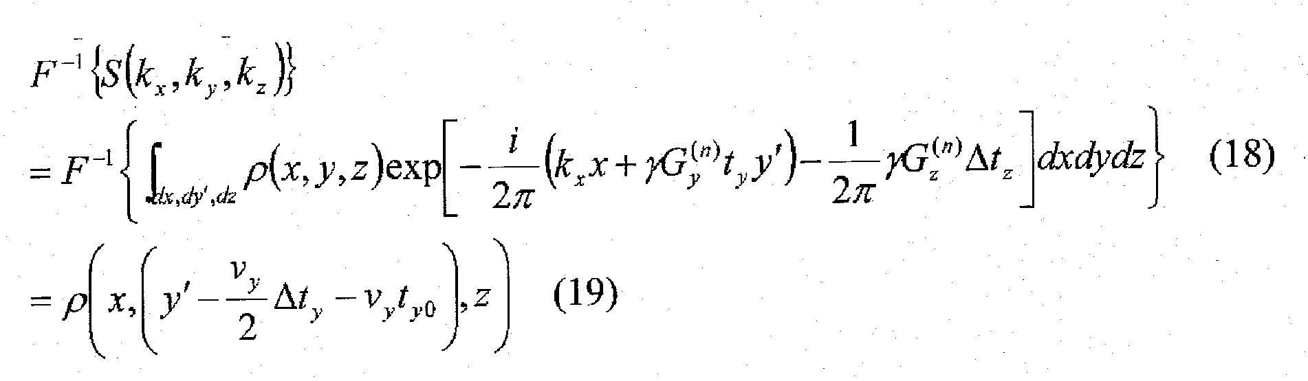
-

-

-

- Thus, it is possible to obtain the corrected image signals S' (kx, ky, kz), based on the three- or more-dimensional image signals S (kx, ky, kz), in accordance with the equation (21). By applying Fourier transformation to the corrected image signals S' (kx, ky, kz), it is possible to obtain accurate image signals in which the influence exerted by the movement in the direction "y" is eliminated.
- The measurement device and the measurement method both in accordance with the present invention are useful as an apparatus and a method for obtaining images of an object by virtue of various magnetic resonances such as electron spin resonance and nuclear magnetic resonance. In particular, the present invention preferably provides accurate images in which the influence exerted by a moving velocity of a moving object is eliminated, in a measurement device and a measurement method for obtaining images of an object, such as functional images and morphologic images, by virtue of magnetic resonance.
Claims (15)
- A measurement device for obtaining images of an object to be measured by virtue of magnetic resonance, comprising:magnetic-field generating means for generating a magnetic field to excite magnetic resonance of said object;moving means for moving one of said object and said magnetic-field generating means to thereby move said object in a magnetic field generated by said magnetic-field generating means;measurement means for applying a gradient magnetic field in at least one of a moving direction "y" in which said object moves relative to said magnetic-field generating means, and a direction "x" perpendicular to said moving direction "y" to thereby obtain image signals of said object by virtue of at least one of phase-encoding and frequency-encoding without stopping said object or said magnetic-field generating means while they are being moved by said moving means; andcorrection means for eliminating influence on said image signals derived from movement of said object in said moving direction "y" to provide corrected image signals.
- The measurement device as set forth in claim 1, wherein said correction means provides said corrected image signals in accordance with the following equation:

wherein
S (kx, ky) indicates said image signals,
S' (kx, ky) indicates said corrected image signals,
each of kx and ky indicates a spatial frequency in said directions "x" and "y" respectively,
"γ " indicates a gyromagnetic ratio,
"Gy (n)" indicates an intensity of a gradient magnetic field of said phase-encoding or said frequency-encoding in n-th measurement,
"vy" indicates a moving velocity in the moving direction "y",
"Δty" indicates a period of time during which said phase-encoding or said frequency-encoding is applied, and
"ty0" indicates a period of time until said phase-encoding or said frequency-encoding starts being applied. - The measurement device as set forth in claim 2, wherein said correction means provides said corrected image signals in accordance with the following equation:

wherein
S (kx, ky, kz) indicates said image signals,
S'(kx, ky, kz) indicates said corrected image signals,
each of kx, ky and kz indicates a spatial frequency in said direction "x", said direction "y", and a direction "z", respectively,
"γ " indicates a gyromagnetic ratio,
"Gy (n)" indicates an intensity of a gradient magnetic field of said phase-encoding or said frequency-encoding in n-th measurement,
"vy' indicates a moving velocity in the moving direction "y",
"Δty" indicates a period of time during which said phase-encoding or said frequency-encoding is applied, and
"ty0" indicates a period of time until said phase-encoding or said frequency-encoding starts being applied. - The measurement device as set forth in claim 1, wherein said magnetic-field generating means includes means for generating a first magnetic field having a predetermined intensity, and means for generating a second magnetic field having an intensity different from said intensity of said first magnetic-field generating means, and
said moving means moves one of said object, said first magnetic-field generating means, and said second magnetic-field generating means to thereby move said object through magnetic fields generated by said first magnetic-field generating means and said second magnetic-field generating means in this order. - The measurement device as set forth in claim 4, wherein said moving means comprises rotating means which rotates one of said object and said first and second magnetic-field generating means to thereby move said object through magnetic fields generated by said first magnetic-field generating means and said second magnetic-field generating means in this order.
- The measurement device as set forth in claim 4 or 5, wherein one of said first and second magnetic-field generating means excites nuclear magnetic resonance for measurement, and the other excites electron spin resonance for measurement.
- The measurement device as set forth in claim 2, wherein said magnetic-field generating means includes means for generating a first magnetic field having a predetermined intensity, and means for generating a second magnetic field having an intensity different from said intensity of said first magnetic-field generating means, and
said moving means moves one of said object, said first magnetic-field generating means, and said second magnetic-field generating means to thereby move said object through magnetic fields generated by said first magnetic-field generating means and said second magnetic-field generating means in this order. - The measurement device as set forth in claim 7, wherein said moving means comprises rotating means which rotates one of said object and said first and second magnetic-field generating means to thereby move said object through magnetic fields generated by said first magnetic-field generating means and said second magnetic-field generating means in this order.
- The measurement device as set forth in claim 7 or 8, wherein one of said first and second magnetic-field generating means excites nuclear magnetic resonance for measurement, and the other excites electron spin resonance for measurement.
- The measurement device as set forth in claim 3, wherein said magnetic-field generating means includes means for generating a first magnetic field having a predetermined intensity, and means for generating a second magnetic field having an intensity different from said intensity of said first magnetic-field generating means, and
said moving means moves one of said object, said first magnetic-field generating means, and said second magnetic-field generating means to thereby move said object through magnetic fields generated by said first magnetic-field generating means and said second magnetic-field generating means in this order. - The measurement device as set forth in claim 10, wherein said moving means comprises rotating means which rotates one of said object and said first and second magnetic-field generating means to thereby move said object through magnetic fields generated by said first magnetic-field generating means and said second magnetic-field generating means in this order.
- The measurement device as set forth in claim 10 or 11, wherein one of said first and second magnetic-field generating means excites nuclear magnetic resonance for measurement, and the other excites electron spin resonance for measurement.
- A measurement method for obtaining images of an object to be measured by virtue of magnetic resonance, comprising:moving one of said object and magnetic-field generating means which generates a magnetic field to excite magnetic resonance of said object to thereby move said object through a magnetic field generated by said magnetic-field generating means;applying a gradient magnetic field in at least one of a moving direction "y" in which said object moves relative to said magnetic-field generating means, and a direction "x" perpendicular to said moving direction "y" to thereby obtain image signals of said object by virtue of at least one of phase-encoding and frequency-encoding without stopping said object or said magnetic-field generating means while they are being moved; and
eliminating influence on said image signals derived from movement of said object in said moving direction "y" to provide corrected image signals. - The measurement method as set forth in claim 13, wherein said corrected image signals are calculated in accordance with the following equation:

wherein
S (kx, ky) indicates said image signals,
S' (kx, ky) indicates said corrected image signals,
each of kx and ky indicates a spatial frequency in said directions "x" and "y" respectively,
"γ " indicates a gyromagnetic ratio,
"Gy (n)" indicates an intensity of a gradient magnetic field of said phase-encoding or said frequency-encoding in n-th measurement,
"vy" indicates a moving velocity in the moving direction "y",
"Δty" indicates a period of time during which said phase-encoding or said frequency-encoding is applied, and
"ty0" indicates a period of time until said phase-encoding or said frequency-encoding starts being applied. - The measurement method as set forth in claim 13, wherein said corrected image signals are calculated in accordance with the following equation:

wherein
S (kx, ky, kz) indicates said image signals,
S'(kx, ky, kz) indicates said corrected image signals,
each of kx, ky and kz indicates a spatial frequency in said direction "x", said direction "y", and a direction "z", respectively,
"γ " indicates a gyromagnetic ratio,
"Gy (n)" indicates an intensity of a gradient magnetic field of said phase-encoding or said frequency-encoding in n-th measurement,
"vy" indicates a moving velocity in the moving direction "y",
"Δty" indicates a period of time during which said phase-encoding or said frequency-encoding is applied, and
"ty0" indicates a period of time until said phase-encoding or said frequency-encoding starts being applied.
Applications Claiming Priority (2)
| Application Number | Priority Date | Filing Date | Title |
|---|---|---|---|
| JP2009077389A JP5252444B2 (en) | 2009-03-26 | 2009-03-26 | Measuring device and measuring method |
| PCT/JP2010/055264 WO2010110384A1 (en) | 2009-03-26 | 2010-03-25 | Measuring instrument and measurement method |
Publications (2)
| Publication Number | Publication Date |
|---|---|
| EP2412309A1 true EP2412309A1 (en) | 2012-02-01 |
| EP2412309A4 EP2412309A4 (en) | 2013-07-03 |
Family
ID=42781075
Family Applications (1)
| Application Number | Title | Priority Date | Filing Date |
|---|---|---|---|
| EP10756180.5A Withdrawn EP2412309A4 (en) | 2009-03-26 | 2010-03-25 | MEASURING INSTRUMENT AND MEASURING METHOD |
Country Status (4)
| Country | Link |
|---|---|
| US (1) | US8896311B2 (en) |
| EP (1) | EP2412309A4 (en) |
| JP (1) | JP5252444B2 (en) |
| WO (1) | WO2010110384A1 (en) |
Cited By (1)
| Publication number | Priority date | Publication date | Assignee | Title |
|---|---|---|---|---|
| EP2869078A4 (en) * | 2012-07-02 | 2016-06-15 | MAGNETIC FIELD APPLICATION DEVICE |
Families Citing this family (6)
| Publication number | Priority date | Publication date | Assignee | Title |
|---|---|---|---|---|
| WO2011052760A1 (en) | 2009-10-29 | 2011-05-05 | 国立大学法人九州大学 | Method for detecting endogenous biomolecule |
| WO2014007122A1 (en) | 2012-07-02 | 2014-01-09 | 日立金属株式会社 | Magnetic circuit |
| WO2014107205A2 (en) * | 2012-10-11 | 2014-07-10 | The Penn State Research Foundation | Zero- & Low-Field Transport Detection System |
| WO2014196525A1 (en) * | 2013-06-03 | 2014-12-11 | 国立大学法人九州大学 | Measurement apparatus and measurement method |
| DE202015103602U1 (en) * | 2015-06-18 | 2015-10-01 | Aspect Imaging Ltd. | Apparatus for three-dimensional anatomical imaging and radiation therapy |
| WO2017217340A1 (en) | 2016-06-13 | 2017-12-21 | 国立大学法人九州大学 | Free radical consumption speed information acquisition method and nash determination method |
Family Cites Families (8)
| Publication number | Priority date | Publication date | Assignee | Title |
|---|---|---|---|---|
| US6912415B2 (en) | 2001-04-09 | 2005-06-28 | Mayo Foundation For Medical Education And Research | Method for acquiring MRI data from a large field of view using continuous table motion |
| US6538444B2 (en) * | 2001-07-27 | 2003-03-25 | The University Of Chicago | Two dimensional B1-gradient NMR imager |
| US7123008B1 (en) * | 2002-04-19 | 2006-10-17 | Fonar Corporation | Positional magnetic resonance imaging |
| JP2006204551A (en) * | 2005-01-28 | 2006-08-10 | Kyushu Univ | Biological measuring device and method |
| WO2006117922A1 (en) * | 2005-04-28 | 2006-11-09 | Hitachi Medical Corporation | Magnetic resonance imaging apparatus |
| JP4991689B2 (en) * | 2006-02-13 | 2012-08-01 | 株式会社日立メディコ | Magnetic resonance imaging apparatus and method |
| US8008917B2 (en) * | 2007-02-28 | 2011-08-30 | Esaote, S.P.A. | Magnetic resonance imaging apparatus |
| WO2008154059A2 (en) * | 2007-04-02 | 2008-12-18 | Regents Of The University Of California | Rotating frame gradient fields for mri and nmr in low polarizing magnetic fields |
-
2009
- 2009-03-26 JP JP2009077389A patent/JP5252444B2/en not_active Expired - Fee Related
-
2010
- 2010-03-25 US US13/258,743 patent/US8896311B2/en not_active Expired - Fee Related
- 2010-03-25 WO PCT/JP2010/055264 patent/WO2010110384A1/en not_active Ceased
- 2010-03-25 EP EP10756180.5A patent/EP2412309A4/en not_active Withdrawn
Cited By (1)
| Publication number | Priority date | Publication date | Assignee | Title |
|---|---|---|---|---|
| EP2869078A4 (en) * | 2012-07-02 | 2016-06-15 | MAGNETIC FIELD APPLICATION DEVICE |
Also Published As
| Publication number | Publication date |
|---|---|
| JP5252444B2 (en) | 2013-07-31 |
| WO2010110384A1 (en) | 2010-09-30 |
| US8896311B2 (en) | 2014-11-25 |
| JP2010227247A (en) | 2010-10-14 |
| US20120068705A1 (en) | 2012-03-22 |
| EP2412309A4 (en) | 2013-07-03 |
Similar Documents
| Publication | Publication Date | Title |
|---|---|---|
| JP5559223B2 (en) | Magnetic resonance imaging system | |
| US8896311B2 (en) | Measurement device and measurement method | |
| EP2130058B1 (en) | Fast magnetic resonance spectroscopic imaging | |
| EP2296546B1 (en) | Measurement device and measurement method | |
| JPH0348814B2 (en) | ||
| US9086446B2 (en) | Method and system for B1 field mapping in magnetic resonance imaging | |
| CN112630713B (en) | Magnetic resonance imaging method, system, electronic device and storage medium | |
| CN112798995B (en) | Motion monitoring method applied to magnetic resonance imaging and magnetic resonance imaging system | |
| US8723517B2 (en) | Reduction of slice select artifacts in half pulse excitations used in ultrashort TE (UTE) imaging | |
| EP3803428B1 (en) | Motion detection in cest magnetic resonance imaging based on z-spectrum analysis | |
| US10254373B2 (en) | Method and apparatus for acquiring magnetic resonance data with navigator scans on opposite sides of the examination region | |
| JP4138258B2 (en) | Magnetic resonance imaging system | |
| CN104955390A (en) | Magnetic resonance imaging device and measurement method thereof | |
| JP5154311B2 (en) | Magnetic resonance imaging apparatus and neurotransmitter quantification method | |
| JPH0549610A (en) | Magnetic resonance diagnostic device | |
| JPS6266846A (en) | NMR inspection device using chemical shift values | |
| US10918744B2 (en) | Biometric method | |
| JP2012095891A (en) | Magnetic resonance imaging apparatus | |
| EP4116728A1 (en) | Nuclear magnetic resonance measurement method and nuclear magnetic resonance apparatus | |
| Schwerter et al. | Advanced software and hardware control methods for improved static and dynamic B0 shimming in magnetic resonance imaging | |
| JP3152690B2 (en) | Magnetic resonance imaging | |
| JPS60166849A (en) | Nmr image apparatus | |
| JP2619398B2 (en) | Inspection equipment using nuclear magnetic resonance | |
| Hill | Developments in quantitative magnetic resonance imaging | |
| JPH0576515A (en) | MR imaging method |
Legal Events
| Date | Code | Title | Description |
|---|---|---|---|
| PUAI | Public reference made under article 153(3) epc to a published international application that has entered the european phase |
Free format text: ORIGINAL CODE: 0009012 |
|
| 17P | Request for examination filed |
Effective date: 20111025 |
|
| AK | Designated contracting states |
Kind code of ref document: A1 Designated state(s): AT BE BG CH CY CZ DE DK EE ES FI FR GB GR HR HU IE IS IT LI LT LU LV MC MK MT NL NO PL PT RO SE SI SK SM TR |
|
| DAX | Request for extension of the european patent (deleted) | ||
| A4 | Supplementary search report drawn up and despatched |
Effective date: 20130604 |
|
| RIC1 | Information provided on ipc code assigned before grant |
Ipc: G01R 33/48 20060101ALI20130528BHEP Ipc: G01R 33/38 20060101ALN20130528BHEP Ipc: A61B 5/055 20060101AFI20130528BHEP Ipc: G01R 33/60 20060101ALI20130528BHEP Ipc: G01N 24/10 20060101ALI20130528BHEP Ipc: G01R 33/44 20060101ALN20130528BHEP Ipc: G01R 33/565 20060101ALI20130528BHEP Ipc: G01R 33/563 20060101ALI20130528BHEP |
|
| 17Q | First examination report despatched |
Effective date: 20150617 |
|
| STAA | Information on the status of an ep patent application or granted ep patent |
Free format text: STATUS: THE APPLICATION IS DEEMED TO BE WITHDRAWN |
|
| 18D | Application deemed to be withdrawn |
Effective date: 20171003 |