EP2410798A1 - Method and device for controlling transmission delay in a coordinated multi-point transmission system - Google Patents
Method and device for controlling transmission delay in a coordinated multi-point transmission system Download PDFInfo
- Publication number
- EP2410798A1 EP2410798A1 EP10753123A EP10753123A EP2410798A1 EP 2410798 A1 EP2410798 A1 EP 2410798A1 EP 10753123 A EP10753123 A EP 10753123A EP 10753123 A EP10753123 A EP 10753123A EP 2410798 A1 EP2410798 A1 EP 2410798A1
- Authority
- EP
- European Patent Office
- Prior art keywords
- unsynchronized
- base station
- synchronization information
- sending
- data block
- Prior art date
- Legal status (The legal status is an assumption and is not a legal conclusion. Google has not performed a legal analysis and makes no representation as to the accuracy of the status listed.)
- Withdrawn
Links
- 230000005540 biological transmission Effects 0.000 title claims abstract description 145
- 238000000034 method Methods 0.000 title claims abstract description 63
- 230000001360 synchronised effect Effects 0.000 claims abstract description 128
- 238000004891 communication Methods 0.000 claims abstract description 15
- 239000011159 matrix material Substances 0.000 claims description 143
- 230000002045 lasting effect Effects 0.000 claims description 16
- 238000001514 detection method Methods 0.000 abstract description 56
- 230000003247 decreasing effect Effects 0.000 abstract description 2
- 230000001427 coherent effect Effects 0.000 description 23
- 238000010586 diagram Methods 0.000 description 11
- 125000004122 cyclic group Chemical group 0.000 description 1
- 238000012986 modification Methods 0.000 description 1
- 230000004048 modification Effects 0.000 description 1
- 230000011664 signaling Effects 0.000 description 1
Images




Classifications
-
- H—ELECTRICITY
- H04—ELECTRIC COMMUNICATION TECHNIQUE
- H04W—WIRELESS COMMUNICATION NETWORKS
- H04W56/00—Synchronisation arrangements
- H04W56/004—Synchronisation arrangements compensating for timing error of reception due to propagation delay
-
- H—ELECTRICITY
- H04—ELECTRIC COMMUNICATION TECHNIQUE
- H04W—WIRELESS COMMUNICATION NETWORKS
- H04W56/00—Synchronisation arrangements
-
- H—ELECTRICITY
- H04—ELECTRIC COMMUNICATION TECHNIQUE
- H04B—TRANSMISSION
- H04B7/00—Radio transmission systems, i.e. using radiation field
- H04B7/02—Diversity systems; Multi-antenna system, i.e. transmission or reception using multiple antennas
- H04B7/022—Site diversity; Macro-diversity
- H04B7/024—Co-operative use of antennas of several sites, e.g. in co-ordinated multipoint or co-operative multiple-input multiple-output [MIMO] systems
Definitions
- the present invention relates to COMP (Coordinated Multi-Point) transmission in a wireless communication system, especially to the coherent transmission in the COMP transmission.
- COMP Coordinatd Multi-Point
- the influence of propagation delay on the bit error ratio performance of a receiver ties to the transmission manner.
- the bit error ratio performance of a receiver adopting non-coherent transmission is better than the bit error ratio performance of a receiver adopting coherent transmission.
- the bit error ratio performance of a receiver when the propagation delay is less than a CP is better than the bit error ratio performance of a receiver when the propagation delay is greater than a CP.
- the DL (downlink) coherent transmission between COMP cells can obtain greater gain than non-coherent transmission.
- the performance of DL coherent transmission greatly deteriorates due to the propagation delay, and the performance of coherent transmission even becomes equivalent to that of the non-coherent transmission when the propagation delay is large.
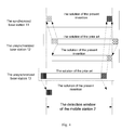
- Fig.1 shows a schematic diagram of the resulted problem of non-synchronization due to different propagation delay of three BSs (Base Station) in DL coherent transmission according to the prior art.
- the region between the left and right dashed lines in Fig. 1 denotes the detection window of MS 2' (mobile station).
- the three BSs 11', 12' and 13' achieve GPS (Global Positioning System) synchronization and send DL data to the MS 2' simultaneously.
- the MS 2' and the BS 11' achieve synchronization, that is, DL data sent by the BS 11' is just detected completely within the detection window of the MS 2'.
- the MS 2' can only detect part of data from the BS 12' and the BS 13' respectively within its detection window due to the problem of propagation delay. As shown in Fig.1 , part of tail data of the BS 12' will fall outside of the detection window of the MS 2', while part of head data of the BS 13' will fall outside of the detection window of the MS 2'.
- the present invention proposes a method and device for controlling propagation delay in a base station of a wireless communication system based on COMP transmission.
- BS when sending downlink data to a MS, BS processes part of data of one or more other unsynchronized base stations and sends the processed part of data to the MS at one or more specific time slots simultaneously.
- a method of controlling propagation delay in a base station of a wireless communication system based on COMP transmission comprising the steps of: when sending downlink data to a mobile station, processing part of data of one or more other unsynchronized base stations and sending the processed part of data to the mobile station at one or more specific time slots simultaneously.
- a method of assisting to control propagation delay in an unsynchronized base station of a wireless communication system based on COMP transmission wherein when out-of-synchronization information corresponding to the unsynchronized base station is larger than 0, the method comprises the steps of: sending to a mobile station downlink data to be transmitted with head data block corresponding to the length of the out-of-synchronization information clipped.
- a method of assisting to control propagation delay in an unsynchronized base station of a wireless communication system based on COMP transmission wherein when out-of-synchronization information corresponding to the unsynchronized base station is less than 0, the method comprises the steps of: postponing transmission starting moment for the length of the out-of-synchronization information, and sending to a mobile station downlink data to be transmitted with tail data block corresponding to said length of the out-of-synchronization information clipped.
- a control device for controlling propagation delay in a base station of a wireless communication system based on COMP transmission, wherein the control device is used for, when sending downlink data to a mobile station, processing part of data of one or more other unsynchronized base stations and sending the processed part of data to the mobile station at one or more specific time slots simultaneously.
- a first assisting control device for assisting to control propagation delay in an unsynchronized base station of a wireless communication system based on COMP transmission, wherein when out-of-synchronization information corresponding to the unsynchronized base station is larger than 0, the first assisting control device comprises: a fourth sending means, for sending to a mobile station downlink data to be transmitted with head data block corresponding to the length of the out-of-synchronization information clipped.
- a second assisting control device for assisting to control propagation delay in an unsynchronized base station of a wireless communication system based on COMP transmission, wherein when out-of-synchronization information corresponding to the unsynchronized base station is less than 0, the second assisting control device comprises: a fifth sending means, for postponing transmission starting moment for the length of the out-of-synchronization information, and sending to a mobile station downlink data to be transmitted with tail data block corresponding to said length of the out-of-synchronization information clipped.
- a plurality of BSs serve one MS. Because the transmission distances from each of the plurality of BSs to the MS are different, it causes different DL propagation delay from each BS to the MS.
- the MS establishes synchronization with one of the plurality of BSs, DL data that is sent to the MS by the synchronized BS will completely fall within the detection window of the MS, but part of DL data that is sent to the MS by other unsynchronized BSs will fall outside of the detection window of the MS due to the propagation delay, so that the receiving performance of the MS deteriorates.
- the synchronized BS may process part of data of one or more other unsynchronized BSs and send the processed part of data to the MS at one or more specific time slots simultaneously, so that DL data that is sent to the MS by one or more other unsynchronized BSs all falls within the detection window of the MS.
- the unsynchronized BS may also process part of data of one or more other unsynchronized BSs and send the processed part of data to the MS at one or more specific time slots simultaneously.
- Fig.2 shows a schematic diagram of a network of COMP transmission system based on DL coherent transmission.
- the BS 11, the BS 12, the BS 13 and the MS 2 are shown in Fig.2 .
- the BS 11, the BS 12 and the BS 13 achieve synchronization of GPS and send DL data to the MS 2 simultaneously.
- the MS 2 and the BS 11 achieve synchronization, and DL data that is sent to the MS 2 by the synchronized BS 11 completely falls within the detection window of the MS 2.
- the propagation distance from the unsynchronized BS 12 to the MS 2 is greater than the propagation distance from the synchronized BS 11 to the MS 2, and part of tail data in DL data that is sent to the MS 2 by the unsynchronized BS 12 falls outside of the detection window of the MS2 due to propagation delay.
- the propagation distance from the unsynchronized BS 13 to the MS 2 is less than the propagation distance from the synchronized BS 11 to the MS 2, part of head data in DL data that is sent to the MS 2 by the unsynchronized BS 13 falls outside of the detection window of the MS 2 due to propagation delay.
- the present invention will be descried by taking it as example that the COMP transmission system based on DL coherent transmission comprises three BSs simultaneously serving one MS, but those skilled in the art should understand that the number of BSs in the COMP transmission system based on DL coherent transmission of the present invention is not limited to three.
- the synchronized BS 11, the unsynchronized BS 12 and the unsynchronized BS 13 perform backhaul of data and signaling via X2 interface before the three BSs starts to send DL data to the MS 2, therefore, any one of the three BSs knows DL data to be transmitted, channel transmission matrix H and out-of-synchronization information (namely propagation delay from other BSs to the MS 2) from other BSs to the MS 2.
- the synchronized BS 11 will receive backhaul information respectively from the unsynchronized BS 12 and the unsynchronized BS 13.
- backhaul information that has been received from the unsynchronized BS 12 by the synchronized BS 11 comprises DL data that is to be sent from the unsynchronized BS 12 to the MS 2, the channel transmission matrix of the DL channel from the unsynchronized BS 12 to the MS 2 and out-of-synchronization information of the unsynchronized BS 12 and the MS 2, namely propagation delay from the unsynchronized BS 12 to the MS 2; similarly, backhaul information that has been received from the unsynchronized BS 13 by the synchronized BS 11 comprises DL data that is to be sent from the unsynchronized BS 13 to the MS 2, the channel transmission matrix of the DL channel from the unsynchronized BS 13 to the MS 2 and out-of-synchronization information of the unsynchronized BS 13 and the MS 2, namely propagation delay from the unsynchronized BS 13 to the MS 2.
- the unsynchronized BS 12 will also receive backhaul information respectively from the synchronized BS 11 and the unsynchronized BS 13; the unsynchronized BS 13 will also receive backhaul information respectively from the synchronized BS 11 and the unsynchronized BS 12, which will not be described in detail for the purpose of simplicity.
- the first row corresponds to DL data from the synchronized BS 11 that is received within the detection window of the MS 2 in the solution of the present invention.
- the upper portion of the second row corresponds to DL data from the unsynchronized BS 12 that is received within the detection window of the MS 2 in the solution of the prior art
- the lower portion of the second row corresponds to DL data from the unsynchronized BS 12 that is received within the detection window of the MS 2 in the solution of the present invention.
- the upper portion of the third row corresponds to DL data from the unsynchronized BS 13 that is received within the detection window of the MS 2 in the solution of the prior art
- the lower portion of the third row corresponds to DL data from the unsynchronized BS 13 that is received within the detection window of the MS 2 in the solution of the present invention.
- the synchronized BS 11 respectively receives backhaul information from the unsynchronized BS 12 and the unsynchronized BS 13 via X2 interface.
- backhaul message that is received from the unsynchronized BS 12 by the synchronized BS 11 comprises DL data to be transmitted from the unsynchronized BS 12 to the MS 2, the channel transmission matrix of DL channel from the unsynchronized BS 12 to the MS 2 and out-of-synchronization information of the unsynchronized BS 12 and the MS 2, namely propagation delay from the unsynchronized BS 12 to the MS 2;
- backhaul message that is received from the unsynchronized BS 13 by the synchronized BS 11 comprises DL data to be transmitted from the unsynchronized BS 13 to the MS 2, the channel transmission matrix of DL channel from the unsynchronized BS 13 to the MS 2 and out-of-synchronization information of the unsynchronized BS 13 and the MS 2, namely propagation delay from the unsynchronized BS 13 to the MS
- the synchronized BS 11 respectively determines whether out-of-synchronization information in backhaul information from the unsynchronized BS 12 and the unsynchronized BS 13 is greater than 0.
- out-of-synchronization information from the synchronized BS 11 to the MS 2 is considered as 0.
- out-of-synchronization information corresponding to the unsynchronized BS 12 is greater than 0; and because the propagation distance from the unsynchronized BS 13 to the MS 2 is less than the propagation distance from the synchronized BS 11 to the MS 2, out-of-synchronization information corresponding to the unsynchronized BS 13 is less than 0.
- out-of-synchronization information corresponding to the unsynchronized BS 12 is greater than 0, in the step S13, when sending DL data to the MS 2, the synchronized BS 11 processes head data block corresponding to the length of the out-of-synchronization information in DL data sent by the unsynchronized BS 12 and sends the processed head data block to the MS 2 at a specific time slot simultaneously.
- the specific time slot is the start time slot, lasting the length of the out-of-synchronization information, within the time slot occupied by the synchronized base station 11 for sending DL data.
- the unsynchronized BS 12 sends to the MS 2 DL data to be transmitted with the head data block corresponding to the length of the out-of-synchronization information clipped.
- the synchronized BS 11 processes head data block corresponding to the length of 0.1 ⁇ s in DL data sent by the unsynchronized BS 12 and sends the processed head data block to the MS 2 at the start time slot of the length of 0.1 ⁇ s for sending DL data simultaneously.
- the unsynchronized BS 12 sends to the MS 2 DL data to be transmitted with the head data block corresponding to the length of 0.1 ⁇ s clipped.
- the upper portion of the second row corresponds to DL data from the unsynchronized BS 12 that is received within the detection window of the MS 2 in the solution of the prior art, because of propagation delay such as 0.1 ⁇ s between the unsynchronized BS 12 and the MS 2, data block (shown as in Fig. 4 ) with the length of 0.1 ⁇ s falls outside of the detection window of the MS 2 in the solution of the prior art.
- head data block shown as in Fig.
- DL data that is sent to the MS 2 by the unsynchronized BS 12 is the DL data with head data block corresponding to the length of 0.1 ⁇ s clipped. Therefore, it may be seen from the solution of the present invention of the lower portion of the second row that DL data (namely DL data with head data block corresponding to the length of 0.1 ⁇ s clipped) that is received from the unsynchronized BS 12 by the MS 2 falls within the detection window of the MS 2 completely. And the head data block sent by the synchronized BS 11 instead of the unsynchronized BS 12 falls within the detection window of the MS 2, the head data block being denoted by corresponding to the first row in Fig.4 .
- the aforesaid processing is multiplying the head data block to be transmitted by the channel transmission matrix of the DL channel from the unsynchronized BS 12 to the MS 2 and the precoding matrix of the unsynchronized BS 12, as well as the inverse matrix of the channel transmission matrix of the DL channel from the synchronized BS 11 to the MS 2 and the inverse matrix of the precoding matrix of the synchronized BS 11.
- the synchronized BS 11 Before sending to the MS 2 the head data block S 21 of the unsynchronized BS 12, the synchronized BS 11 firstly processes the head data block S 21 , that is, the head data block S 21 is transformed into F 1 - 1 ⁇ H 1 - 1 ⁇ H 2 ⁇ F 2 ⁇ S 21 , wherein, F 1 - 1 is the inverse matrix of the precoding matrix of the synchronized BS 11, H 1 - 1 is the inverse matrix of the channel transmission matrix of the DL channel from the synchronized BS 11 to the MS 2, H 2 is the channel transmission matrix of the DL channel from the unsynchronized BS 12 to the MS 2, and F 2 is the precoding matrix of the unsynchronized BS 12.
- the synchronized BS 11 may send the processed head data block of the unsynchronized BS 12 by using the antenna for sending its own DL data; but if the transmission manner of space multiplexing is used between BS and MS, the synchronized BS 11 should use extra transmitting antenna to transmit the processed head data block of the unsynchronized BS 12.
- step S 14 when sending DL data to the MS 2, the synchronized BS 11 processes tail data block corresponding to the length of the out-of-synchronization information in DL data sent by the unsynchronized BS 13 and sends the processed tail data block to the MS 2 at a specific time slot simultaneously.
- the specific time slot is the final time slot, lasting the length of the out-of-synchronization information, within the time slot occupied by the synchronized base station 11 for sending DL signal.
- the unsynchronized BS 13 postpones the transmission starting moment for the length of the out-of-synchronization information and then sends to the MS 2 DL data to be transmitted with the tail data block corresponding to the length of the out-of-synchronization information clipped.
- the synchronized BS 11 processes tail data block corresponding to the length of 0.1 ⁇ s in DL data sent by the unsynchronized BS 13 and sends the processed tail data block to the MS 2 at the final time slot of the length of 0.1 ⁇ s for sending DL data simultaneously.
- the unsynchronized BS 13 postpones the transmission starting moment for the length of 0.1 ⁇ s and then sends to the MS 2 DL data to be transmitted with the tail data block corresponding to the length of 0.1 ⁇ s clipped.
- the upper portion of the third row corresponds to DL data from the unsynchronized BS 13 that is received within the detection window of the MS 2 in the solution of the prior art, because of propagation delay such as -0.1 ⁇ s between the unsynchronized BS 13 and the MS 2, data block (shown as in Fig. 4 ) with the length of 0.1 ⁇ s falls outside of the detection window of the MS 2 in the solution of the prior art.
- tail data block shown as in Fig.
- the aforesaid processing is multiplying the tail data block to be transmitted by the channel transmission matrix of the DL channel from the unsynchronized BS 13 to the MS 2 and the precoding matrix of the unsynchronized BS 13, as well as the inverse matrix of the channel transmission matrix of the DL channel from the synchronized BS 11 to the MS 2 and the inverse matrix of the precoding matrix of the synchronized BS 11.
- the synchronized BS 11 Before sending to the MS 2 the tail data block S31 of the unsynchronized BS 13, the synchronized BS 11 firstly processes the tail data block S 31 , that is, the tail data block S 31 is transformed into F 1 - 1 ⁇ H 1 - 1 ⁇ H 3 ⁇ F 3 ⁇ S 31 , wherein, F 1 - 1 is the inverse matrix of the precoding matrix of the synchronized BS 11, H 1 - 1 is the inverse matrix of the channel transmission matrix of the DL channel from the synchronized BS 11 to the MS 2, H 3 is the channel transmission matrix of the DL channel from the unsynchronized BS 13 to the MS 2, F 3 is the precoding matrix of the unsynchronized BS 13.
- the synchronized BS 11 may send the processed tail data block of the unsynchronized BS 13 by using the antenna for sending its own DL data; but if the transmission manner of space multiplexing is used between BS and MS, the synchronized BS 11 should use extra transmitting antenna to transmit the processed tail data block of the unsynchronized BS 13.
- the synchronized BS 11 processes part of data of the unsynchronized BS 12 and the unsynchronized BS 13 and sends the processed part of data to the MS 2 respectively at specific time slots simultaneously.
- the unsynchronized BS 12 processes part of data of the unsynchronized BS 13 and sends the processed part of data of the unsynchronized BS 13 to the MS 2 at specific time slots simultaneously
- the synchronized BS 13 processes part of data of the unsynchronized BS 12 and sends the processed part of data of the unsynchronized BS 12 to the MS 2 at specific time slots simultaneously.
- Fig.5 shows a schematic diagram of the unsynchronized BS 12 processing part of data of the unsynchronized BS 13 and sending the processed part of data of the unsynchronized BS 13 to the MS 2 at specific time slots simultaneously when sending DL data to the MS 2, and the synchronized BS 13 processing part of data of the unsynchronized BS 12 and sending the processed part of data of the unsynchronized BS 12 to the MS 2 at specific time slots simultaneously when sending DL data to the MS 2.
- the first row corresponds to DL data from the synchronized BS 11 that is received within the detection window of the MS 2 in the solution of the present invention.
- the upper portion of the second row corresponds to DL data from the unsynchronized BS 12 that is received within the detection window of the MS 2 in the solution of the prior art
- the lower portion of the second row corresponds to DL data from the unsynchronized BS 12 that is received within the detection window of the MS 2 in the solution of the present invention.
- the upper portion of the third row corresponds to DL data from the unsynchronized BS 13 that is received within the detection window of the MS 2 in the solution of the prior art
- the lower portion of the third row corresponds to DL data from the unsynchronized BS 13 that is received within the detection window of the MS 2 in the solution of the present invention.
- the unsynchronized BS 12 receives backhaul information from the unsynchronized BS 13 via X2 interface.
- backhaul message that is received from the unsynchronized BS 13 by the unsynchronized BS 12 comprises DL data to be transmitted from the unsynchronized BS 13 to the MS 2, the channel transmission matrix of DL channel from the unsynchronized BS 13 to the MS 2 and out-of-synchronization information of the unsynchronized BS 13 and the MS 2, namely propagation delay from the unsynchronized BS 13 to the MS 2.
- the unsynchronized BS 12 determines whether out-of-synchronization information in backhaul information from the unsynchronized BS 13 is greater than 0.
- out-of-synchronization information corresponding to the unsynchronized BS 13 is less than 0.
- out-of-synchronization information corresponding to the unsynchronized BS 13 is less than 0, when sending DL data to the MS 2, the unsynchronized BS 12 processes tail data block corresponding to the length of the out-of-synchronization information in DL data sent by the unsynchronized BS 13 and sends the processed tail data block to the MS 2 at a specific time slot simultaneously.
- the specific time slot is the final time slot, lasting the length of the out-of-synchronization information, within the time slot occupied by the synchronized BS 12 for sending DL data.
- the unsynchronized BS 13 postpones the transmission starting moment for the length of the out-of-synchronization information and sends to the MS 2 DL data to be transmitted with the tail data block corresponding to the length of the out-of-synchronization information clipped.
- the unsynchronized BS 12 processes tail data block corresponding to the length of 0.1 ⁇ s in DL data sent by the unsynchronized BS 13 and sends the processed tail data block to the MS 2 at the final time slot of the length of 0.1 ⁇ s for sending DL data simultaneously.
- the unsynchronized BS 13 postpones the transmission starting moment for the length of 0.1 ⁇ s and then sends to the MS 2 DL data to be transmitted with the tail data block corresponding to the length of 0.1 ⁇ s clipped.
- the upper portion of the third row corresponds to DL data from the unsynchronized BS 13 that received within the detection window of the MS 2 in the solution of the prior art, because of propagation delay such as -0.1 ⁇ s between the unsynchronized BS 13 and the MS 2, data block (shown as in Fig. 5 ) with the length of 0.1 ⁇ s falls outside of the detection window of the MS 2 in the solution of the prior art.
- tail data block shown as in Fig.
- the aforesaid processing is that the unsynchronized BS 12 multiplies the tail data block to be transmitted by the channel transmission matrix of the DL channel from the unsynchronized BS 13 to the MS 2 and the precoding matrix of the unsynchronized BS 13, as well as the inverse matrix of the channel transmission matrix of the DL channel from the unsynchronized BS 12 to the MS 2 and the inverse matrix of the precoding matrix of the unsynchronized BS 12.
- the unsynchronized BS 12 Before sending to the MS 2 the tail data block S 31 of the unsynchronized BS 13, the unsynchronized BS 12 firstly processes the tail data block S 31 , that is, the tail data block S 31 is transformed into F 2 - 1 ⁇ H 2 - 1 ⁇ H 3 ⁇ F 3 ⁇ S 31 , wherein, F 2 - 1 is the inverse matrix of the precoding matrix of the unsynchronized BS 12, H 2 - 1 is the inverse matrix of the channel transmission matrix of the DL channel from the unsynchronized BS 12 to the MS 2, H 3 is the channel transmission matrix of the DL channel from the unsynchronized BS 13 to the MS 2, F 3 is the precoding matrix of the unsynchronized BS 13.
- the unsynchronized BS 12 may send the processed tail data block of the unsynchronized BS 13 by using the antenna for sending its own DL data; but if the transmission manner of space multiplexing is used between BS and MS, the unsynchronized BS 12 should use extra transmitting antenna to transmit the processed tail data block of the unsynchronized BS 13.
- the unsynchronized BS 13 receives backhaul information from the unsynchronized BS 12 via X2 interface.
- backhaul information that is received from the unsynchronized BS 12 by the unsynchronized BS 13 comprises DL data to be transmitted from the unsynchronized BS 12 to the MS 2, the channel transmission matrix of DL channel from the unsynchronized BS 12 to the MS 2 and out-of-synchronization information of the unsynchronized BS 12 and the MS 2, namely propagation delay from the unsynchronized BS 12 to the MS 2.
- the unsynchronized BS 13 determines whether out-of-synchronization information in backhaul information from the unsynchronized BS 12 is greater than 0.
- out-of-synchronization information corresponding to the unsynchronized BS 12 is greater than 0.
- out-of-synchronization information corresponding to the unsynchronized BS 12 is greater than 0, when sending DL data to the MS 2, the unsynchronized BS 13 processes head data block corresponding to the length of the out-of-synchronization information in DL data sent by the unsynchronized BS 12 and sends the processed head data block to the MS 2 at a specific time slot simultaneously.
- the specific time slot is the start time slot, lasting the length of the out-of-synchronization information, within the time slot occupied by the synchronized base station 13 for sending DL signal.
- the unsynchronized BS 12 sends to the MS 2 DL data to be transmitted with the head data block corresponding to the length of the out-of-synchronization information clipped.
- the unsynchronized BS 13 processes head data block corresponding to the length of 0.1 ⁇ s in DL data sent by the unsynchronized BS 12 and sends the processed head data block to the MS 2 at the start time slot of the length of 0.1 ⁇ s for sending DL data simultaneously.
- the unsynchronized BS 12 sends to the MS 2 DL data to be transmitted with the head data block corresponding to the length of 0.1 ⁇ s clipped.
- the upper portion of the second row corresponds to DL data from the unsynchronized BS 12 that is received within the detection window of the MS 2 in the solution of the prior art, because of propagation delay such as 0.1 ⁇ s between the unsynchronized BS 12 and the MS 2, data block (shown as in Fig. 5 ) with the length of 0.1 ⁇ s falls outside of the detection window of the MS 2 in the solution of the prior art.
- head data block shown as in Fig.
- DL data that is sent to the MS 2 by the unsynchronized BS 12 is the DL data with head data block corresponding to the length of 0.1 ⁇ s clipped. Therefore, it may be seen from the solution of the present invention of the lower portion of the second row that DL data (namely DL data with head data block corresponding to the length of 0.1 ⁇ s clipped) that is received from the unsynchronized BS 12 by the MS 2 falls within the detection window of the MS 2 completely. And the head data block sent by the unsynchronized BS 13 instead of the unsynchronized BS 12 falls within the detection window of the MS 2, the head data block being denoted by corresponding to the lower portion of the third row in Fig.5 .
- the unsynchronized BS 13 multiplies the head data block to be transmitted by the channel transmission matrix of the DL channel from the unsynchronized BS 12 to the MS 2 and the precoding matrix of the unsynchronized BS 12, as well as the inverse matrix of the channel transmission matrix of the DL channel from the unsynchronized BS 13 to the MS 2 and the inverse matrix of the precoding matrix of the unsynchronized BS 13.
- the unsynchronized BS 13 Before sending to the MS 2 the head data block S 21 of the unsynchronized BS 12, the unsynchronized BS 13 firstly processes the head data block S 21 , that is, the head data block S 21 is transformed into F 3 - 1 ⁇ H 3 - 1 ⁇ H 2 ⁇ F 2 ⁇ S 21 , wherein, F 3 - 1 is the inverse matrix of the precoding matrix of the unsynchronized BS 13, H 3 - 1 is the inverse matrix of the channel transmission matrix of the DL channel from the unsynchronized BS 13 to the MS 2, H 2 is the channel transmission matrix of the DL channel from the unsynchronized BS 12 to the MS 2, F 2 is the precoding matrix of the unsynchronized BS 12.
- the unsynchronized BS 13 may send the processed head data block of the unsynchronized BS 12 by using the antenna for sending its own DL data; but if the transmission manner of space multiplexing is used between BS and MS, the unsynchronized BS 13 should use extra transmitting antenna to transmit the processed head data block of the unsynchronized BS 12.
- an unsynchronized BS 14 is included, and the propagation distance from the unsynchronized BS 14 to the MS 2 is greater than the propagation distance from the unsynchronized BS 12 to the MS 2.
- out-of-synchronization information corresponding to the unsynchronized BS 12 is 0.1 ⁇ s and out-of-synchronization information corresponding to the unsynchronized BS 14 is 0.2 ⁇ s.
- the head data block corresponding to the length of 0.2 ⁇ s in DL data to be transmitted of the unsynchronized BS 14 may be sent to the MS 2 at a specific time slot by the synchronized BS 11 simultaneously when the synchronized BS 11 sends DL data, and may also be sent to the MS 2 at a specific time slot by the unsynchronized BS 13 simultaneously when the unsynchronized BS 13 sends DL data.
- the latter 0.1 ⁇ s data block (shown as in Fig.6 ) in the head data block corresponding to the length of 0.2 ⁇ s may be sent to the MS 2 by the unsynchronized BS 12 at the start time slot of the length of 0.1 ⁇ s for sending DL data simultaneously when the unsynchronized BS 12 sends DL data
- the former 0.1 ⁇ s data block (shown as in Fig.6 ) in the head data block corresponding to the length of 0.2 ⁇ s may be sent to the MS 2 by the synchronized BS 11 or the unsynchronized BS 13 at the start time slot of the length of 0.1 ⁇ s for sending DL data simultaneously when the synchronized BS 11 or the unsynchronized BS 13 sends DL data.
- a control device 100 in the synchronized BS 11 processes part of data of the unsynchronized BS 12 and the unsynchronized BS 13 and sends the processed part of data to the MS 2 respectively at specific time slots simultaneously is described.
- the descriptions for Fig.2 and Fig.4 in the preceding context are taken as reference together.
- Fig.7 shows a block diagram of structure of a control device 100 in the synchronized BS 11 for processing part of data of the unsynchronized BS 12 and the unsynchronized BS 13 and sending the processed part of data to the MS 2 at different time slots simultaneously, when sending downlink data to the MS 2, according to one embodiment of the present invention.
- a first receiving means 1001 in control device 100 in the synchronized BS 11 respectively receives backhaul information from the unsynchronized BS 12 and the unsynchronized BS 13 via X2 interface.
- backhaul message that is received from the unsynchronized BS 12 by the first receiving means 1001 comprises DL data to be transmitted from the unsynchronized BS 12 to the MS 2, the channel transmission matrix of DL channel from the unsynchronized BS 12 to the MS 2 and out-of-synchronization information of the unsynchronized BS 12 and the MS 2, namely propagation delay from the unsynchronized BS 12 to the MS 2;
- backhaul message that is received from the unsynchronized BS 13 by the first receiving means 1001 comprises DL data to be transmitted from the unsynchronized BS 13 to the MS 2, the channel transmission matrix of DL channel from the unsynchronized BS 13 to the MS 2 and out-of-synchronization information of the unsynchronized BS 13 and the MS 2, namely propagation delay from the unsynchronized BS
- a first determining means 1002 in the control device 100 in the synchronized BS 11 respectively determines whether out-of-synchronization information in backhaul information from the unsynchronized BS 12 and the unsynchronized BS 13 is greater than 0.
- out-of-synchronization information from the synchronized BS 11 to the MS 2 is considered as 0.
- out-of-synchronization information corresponding to the unsynchronized BS 12 is greater than 0; and because the propagation distance from the unsynchronized BS 13 to the MS 2 is less than the propagation distance from the synchronized BS 11 to the MS 2, out-of-synchronization information corresponding to the unsynchronized BS 13 is less than 0.
- a first sending means 1003 in the control device 100 in the synchronized BS 11 processes head data block corresponding to the length of the out-of-synchronization information in DL data sent by the unsynchronized BS 12 and sends the processed head data block to the MS 2 at a specific time slot simultaneously.
- the specific time slot is the start time slot, lasting the length of the out-of-synchronization information, within the time slot occupied by the first sending means 1003 in the synchronized base station 11 for sending DL data.
- a fourth sending means in a first assisting control device in the unsynchronized BS 12 sends to the MS 2 DL data to be transmitted with the head data block corresponding to the length of the out-of-synchronization information clipped.
- the first sending means 1003 in the synchronized BS 11 processes head data block corresponding to the length of 0.1 ⁇ s in DL data sent by the unsynchronized BS 12 and sends the processed head data block to the MS 2 at the start time slot of the length of 0.1 ⁇ s for sending DL data simultaneously.
- the fourth sending means in the first assisting control device in the unsynchronized BS 12 sends to the MS 2 DL data to be transmitted with the head data block corresponding to the length of 0. 1 ⁇ s clipped.
- the upper portion of the second row corresponds to DL data from the unsynchronized BS 12 that is received within the detection window of the MS 2 in the solution of the prior art, because of propagation delay such as 0.1 ⁇ s between the unsynchronized BS 12 and the MS 2, data block (shown as in Fig. 4 ) with the length of 0.1 ⁇ s falls outside of the detection window of the MS 2 in the solution of the prior art.
- head data block shown as in Fig.
- DL data that is sent to the MS 2 by the fourth sending means in the first assisting control device in the unsynchronized BS 12 is the DL data with head data block corresponding to the length of 0.1 ⁇ s clipped.
- the aforesaid processing is multiplying the head data block to be transmitted by the channel transmission matrix of the DL channel from the unsynchronized BS 12 to the MS 2 and the precoding matrix of the unsynchronized BS 12, as well as the inverse matrix of the channel transmission matrix of the DL channel from the synchronized BS 11 to the MS 2 and the inverse matrix of the precoding matrix of the synchronized BS 11.
- the first sending means 1003 in the synchronized BS 11 Before sending to the MS 2 the head data block S 21 of the unsynchronized BS 12, the first sending means 1003 in the synchronized BS 11 firstly processes the head data block S21, that is, the head data block S 21 is transformed into F 1 - 1 ⁇ H 1 - 1 ⁇ H 2 ⁇ F 2 ⁇ S 21 , wherein, F 1 - 1 is the inverse matrix of the precoding matrix of the synchronized BS 11, H 1 - 1 is the inverse matrix of the channel transmission matrix of the DL channel from the synchronized BS 11 to the MS 2, H 2 is the channel transmission matrix of the DL channel from the unsynchronized BS 12 to the MS 2, and F 2 is the precoding matrix of the unsynchronized BS 12.
- the synchronized BS 11 may send the processed head data block of the unsynchronized BS 12 by using the antenna for sending its own DL data; but if the transmission manner of space multiplexing is used between BS and MS, the synchronized BS 11 should use extra transmitting antenna to transmit the processed head data block of the unsynchronized BS 12.
- the first sending means 1003 in the control device 100 in the synchronized BS 11 processes tail data block corresponding to the length of the out-of-synchronization information in DL data sent by the unsynchronized BS 13 and sends the processed tail data block to the MS 2 at a specific time slot simultaneously.
- the specific time slot is the final time slot, lasting the length of the out-of-synchronization information, within the time slot occupied by the first sending means 1003 in the synchronized base station 11 for sending DL signal.
- a fifth sending means in a second assisting control device in the unsynchronized BS 13 postpones the transmission starting moment for the length of the out-of-synchronization information and then sends to the MS 2 DL data to be transmitted with the tail data block corresponding to the length of the out-of-synchronization information clipped.
- the first sending means 1003 in the synchronized BS 11 processes tail data block corresponding to the length of 0.1 ⁇ s in DL data sent by the unsynchronized BS 13 and sends the processed tail data block to the MS 2 at the final time slot of the length of 0.1 ⁇ s for sending DL data simultaneously.
- the fifth sending means in the second assisting control device in the unsynchronized BS 13 postpones the transmission starting moment for the length of 0.1 ⁇ s and then sends to the MS 2 DL data to be transmitted with the tail data block corresponding to the length of 0.1 ⁇ s clipped.
- the upper portion of the third row corresponds to DL data from the unsynchronized BS 13 that is received within the detection window of the MS 2 in the solution of the prior art, because of propagation delay such as -0.1 ⁇ s between the unsynchronized BS 13 and the MS 2, data block (shown as in Fig. 4 ) with the length of 0.1 ⁇ s falls outside of the detection window of the MS 2 in the solution of the prior art.
- tail data block shown as in Fig.
- the aforesaid processing is multiplying the tail data block to be transmitted by the channel transmission matrix of the DL channel from the unsynchronized BS 13 to the MS 2 and the precoding matrix of the unsynchronized BS 13, as well as the inverse matrix of the channel transmission matrix of the DL channel from the synchronized BS 11 to the MS 2 and the inverse matrix of the precoding matrix of the synchronized BS 11.
- the first sending means 1003 in the synchronized BS 11 firstly processes the tail data block S 31 , that is, the tail data block S 31 is transformed into F 1 - 1 ⁇ H 1 - 1 ⁇ H 3 ⁇ F 3 ⁇ S 31 , wherein, F 1 - 1 is the inverse matrix of the precoding matrix of the synchronized BS 11, H 1 - 1 is the inverse matrix of the channel transmission matrix of the DL channel from the synchronized BS 11 to the MS 2, H 3 is the channel transmission matrix of the DL channel from the unsynchronized BS 13 to the MS 2, F 3 is the precoding matrix of the unsynchronized BS 13.
- the synchronized BS 11 may send the processed tail data block of the unsynchronized BS 13 by using the antenna for sending its own DL data; but if the transmission manner of space multiplexing is used between BS and MS, the synchronized BS 11 should use extra transmitting antenna to transmit the processed tail data block of the unsynchronized BS 13.
- the control device 100 in the synchronized BS 11 processes part of data of the unsynchronized BS 12 and the unsynchronized BS 13 and sends the processed part of data to the MS 2 respectively at specific time slots simultaneously is described.
- the unsynchronized BS 12 processes part of data of the unsynchronized BS 13 and sends the processed part of data of the unsynchronized BS 13 to the MS 2 at specific time slots simultaneously
- the synchronized BS 13 processes part of data of the unsynchronized BS 12 and sends the processed part of data of the unsynchronized BS 12 to the MS 2 at specific time slots simultaneously.
- a second receiving means in a control device in the unsynchronized BS 12 receives backhaul information from the unsynchronized BS 13 via X2 interface.
- backhaul message that is received from the unsynchronized BS 13 by the second receiving means in the control device in the unsynchronized BS 12 comprises DL data to be transmitted from the unsynchronized BS 13 to the MS 2, the channel transmission matrix of DL channel from the unsynchronized BS 13 to the MS 2 and out-of-synchronization information of the unsynchronized BS 13 and the MS 2, namely propagation delay from the unsynchronized BS 13 to the MS 2.
- a second determining means in the control device in the unsynchronized BS 12 determines whether out-of-synchronization information in backhaul information from the unsynchronized BS 13 is greater than 0.
- out-of-synchronization information corresponding to the unsynchronized BS 13 is less than 0.
- a second sending means in the control device in the unsynchronized BS 12 processes tail data block corresponding to the length of the out-of-synchronization information in DL data sent by the unsynchronized BS 13 and sends the processed tail data block to the MS 2 at a specific time slot simultaneously.
- the specific time slot is the final time slot, lasting the length of the out-of-synchronization information, within the time slot occupied by the second sending means in the control device in the synchronized BS 12 for sending DL data.
- the fifth sending means in the second assisting control device in the unsynchronized BS 13 postpones the transmission starting moment for the length of the out-of-synchronization information and sends to the MS 2 DL data to be transmitted with the tail data block corresponding to the length of the out-of-synchronization information clipped.
- the second sending means in the control device in the unsynchronized BS 12 processes tail data block corresponding to the length of 0.1 ⁇ s in DL data sent by the unsynchronized BS 13 and sends the processed tail data block to the MS 2 at the final time slot of the length of 0.1 ⁇ s for sending DL data simultaneously.
- the fifth sending means in the second assisting control device in the unsynchronized BS 13 postpones the transmission starting moment for the length of 0.1 ⁇ s and then sends to the MS 2 DL data to be transmitted with the tail data block corresponding to the length of 0.1 ⁇ s clipped.
- the upper portion of the third row corresponds to DL data from the unsynchronized BS 13 that received within the detection window of the MS 2 in the solution of the prior art, because of propagation delay such as -0.1 ⁇ s between the unsynchronized BS 13 and the MS 2, data block (shown as in Fig. 5 ) with the length of 0.1 ⁇ s falls outside of the detection window of the MS 2 in the solution of the prior art.
- tail data block shown as in Fig.
- the aforesaid processing is that the second sending means in the control device in the unsynchronized BS 12 multiplies the tail data block to be transmitted by the channel transmission matrix of the DL channel from the unsynchronized BS 13 to the MS 2 and the precoding matrix of the unsynchronized BS 13, as well as the inverse matrix of the channel transmission matrix of the DL channel from the unsynchronized BS 12 to the MS 2 and the inverse matrix of the precoding matrix of the unsynchronized BS 12.
- the second sending means in the control device in the unsynchronized BS 12 firstly processes the tail data block S 31 , that is, the tail data block S 31 is transformed into F 2 - 1 ⁇ H 2 - 1 ⁇ H 3 ⁇ F 3 ⁇ S 31 , wherein, F 2 - 1 is the inverse matrix of the precoding matrix of the unsynchronized BS 12, H 2 - 1 is the inverse matrix of the channel transmission matrix of the DL channel from the unsynchronized BS 12 to the MS 2, H 3 is the channel transmission matrix of the DL channel from the unsynchronized BS 13 to the MS 2, F 3 is the precoding matrix of the unsynchronized BS 13.
- the second sending means in the control device in the unsynchronized BS 12 sends the processed tail data block F 2 - 1 ⁇ H 2 - 1 ⁇ H 3 ⁇ F 3 ⁇ S 31 to the MS 2
- the fifth sending means in the second assisting control device in the unsynchronized BS 13 sends to the MS 2 the remaining data S 32 with the tail data block clipped
- the unsynchronized BS 12 may send the processed tail data block of the unsynchronized BS 13 by using the antenna for sending its own DL data; but if the transmission manner of space multiplexing is used between BS and MS, the unsynchronized BS 12 should use extra transmitting antenna to transmit the processed tail data block of the unsynchronized BS 13.
- a third receiving means in the control device in the unsynchronized BS 13 receives backhaul information from the unsynchronized BS 12 via X2 interface.
- backhaul information that is received from the unsynchronized BS 12 by the third receiving means in the control device in the unsynchronized BS 13 comprises DL data to be transmitted from the unsynchronized BS 12 to the MS 2, the channel transmission matrix of DL channel from the unsynchronized BS 12 to the MS 2 and out-of-synchronization information of the unsynchronized BS 12 and the MS 2, namely propagation delay from the unsynchronized BS 12 to the MS 2.
- a third determining means in the control device in the unsynchronized BS 13 determines whether out-of-synchronization information in backhaul information from the unsynchronized BS 12 is greater than 0.
- out-of-synchronization information corresponding to the unsynchronized BS 12 is greater than 0.
- a third sending means in the control device in the unsynchronized BS 13 processes head data block corresponding to the length of the out-of-synchronization information in DL data sent by the unsynchronized BS 12 and sends the processed head data block to the MS 2 at a specific time slot simultaneously.
- the specific time slot is the start time slot, lasting the length of the out-of-synchronization information, within the time slot occupied by the third sending means in the control device in the synchronized base station 13 for sending DL signal.
- the fourth sending means in the first assisting control device in the unsynchronized BS 12 sends to the MS 2 DL data to be transmitted with the head data block corresponding to the length of the out-of-synchronization information clipped.
- the third sending means in the control device in the unsynchronized BS 13 processes head data block corresponding to the length of 0.1 ⁇ s in DL data sent by the unsynchronized BS 12 and sends the processed head data block to the MS 2 at the start time slot of the length of 0.1 ⁇ s for sending DL data simultaneously.
- the fourth sending means in the first assisting control device in the unsynchronized BS 12 sends to the MS 2 DL data to be transmitted with the head data block corresponding to the length of 0.1 ⁇ s clipped.
- the upper portion of the second row corresponds to DL data from the unsynchronized BS 12 that is received within the detection window of the MS 2 in the solution of the prior art, because of propagation delay such as 0.1 ⁇ s between the unsynchronized BS 12 and the MS 2, data block (shown as in Fig. 5 ) with the length of 0.1 ⁇ s falls outside of the detection window of the MS 2 in the solution of the prior art.
- head data block shown as in Fig.
- DL data that is sent to the MS 2 by the fourth sending means in the first assisting control device in the unsynchronized BS 12 is the DL data with head data block corresponding to the length of 0.1 ⁇ s clipped.
- the third sending means in the control device in the unsynchronized BS 13 multiplies the head data block to be transmitted by the channel transmission matrix of the DL channel from the unsynchronized BS 12 to the MS 2 and the precoding matrix of the unsynchronized BS 12, as well as the inverse matrix of the channel transmission matrix of the DL channel from the unsynchronized BS 13 to the MS 2 and the inverse matrix of the precoding matrix of the unsynchronized BS 13.
- the third sending means in the control device in the unsynchronized BS 13 firstly processes the head data block S 21 , that is, the head data block S 21 is transformed into F 2 - 1 ⁇ H 3 - 1 ⁇ H 2 ⁇ F 2 ⁇ S 21 , wherein, F 3 - 1 is the inverse matrix of the precoding matrix of the unsynchronized BS 13, H 3 - 1 is the inverse matrix of the channel transmission matrix of the DL channel from the unsynchronized BS 13 to the MS 2, H 2 is the channel transmission matrix of the DL channel from the unsynchronized BS 12 to the MS 2, F 2 is the precoding matrix of the unsynchronized BS 12.
- the unsynchronized BS 13 may send the processed head data block of the unsynchronized BS 12 by using the antenna for sending its own DL data; but if the transmission manner of space multiplexing is used between BS and MS, the unsynchronized BS 13 should use extra transmitting antenna to transmit the processed head data block of the unsynchronized BS 12.
Landscapes
- Engineering & Computer Science (AREA)
- Computer Networks & Wireless Communication (AREA)
- Signal Processing (AREA)
- Mobile Radio Communication Systems (AREA)
Abstract
Description
- The present invention relates to COMP (Coordinated Multi-Point) transmission in a wireless communication system, especially to the coherent transmission in the COMP transmission.
- Considering the multi-path transmission of a single cell, influence on the bit error ratio performance of a receiver is unacceptable even if propagation delay between two COMP cells is less than a CP (Cyclic Prefix) length.
- Furthermore, the influence of propagation delay on the bit error ratio performance of a receiver ties to the transmission manner. For the same propagation delay, the bit error ratio performance of a receiver adopting non-coherent transmission is better than the bit error ratio performance of a receiver adopting coherent transmission. For the coherent transmission and the non-coherent transmission, the bit error ratio performance of a receiver when the propagation delay is less than a CP is better than the bit error ratio performance of a receiver when the propagation delay is greater than a CP.
- Although the DL (downlink) coherent transmission between COMP cells can obtain greater gain than non-coherent transmission. However, the performance of DL coherent transmission greatly deteriorates due to the propagation delay, and the performance of coherent transmission even becomes equivalent to that of the non-coherent transmission when the propagation delay is large.
-
Fig.1 shows a schematic diagram of the resulted problem of non-synchronization due to different propagation delay of three BSs (Base Station) in DL coherent transmission according to the prior art. The region between the left and right dashed lines inFig. 1 denotes the detection window of MS 2' (mobile station). The three BSs 11', 12' and 13' achieve GPS (Global Positioning System) synchronization and send DL data to the MS 2' simultaneously. The MS 2' and the BS 11' achieve synchronization, that is, DL data sent by the BS 11' is just detected completely within the detection window of the MS 2'. Because the distance from the BS 12' to the MS 2' is farther than the distance from the BS 11' to the MS 2', but the distance from the BS 13' to the MS 2' is nearer than the distance from the BS 11' to the MS 2', the MS 2' can only detect part of data from the BS 12' and the BS 13' respectively within its detection window due to the problem of propagation delay. As shown inFig.1 , part of tail data of the BS 12' will fall outside of the detection window of the MS 2', while part of head data of the BS 13' will fall outside of the detection window of the MS 2'. If the length of data falling outside of the detection window of the MS 2' in DL data, which the BS 12' and the BS 13' respectively send to the MS 2', is greater than a CP, then, the receiving performance of the MS 2' will greatly deteriorate. - For aforesaid problem, there are two solutions in the prior art:
- 1) adding the length of CP to tolerate greater propagation delay;
- 2) replacing coherent transmission with non-coherent transmission. However, for the first solution, the system efficiency will greatly decrease due to the adding of the length of CP. Moreover, if the propagation delay is still greater than the length of CP, the bit error ratio performance of a receiver will still be greatly influenced.
- For the second solution, it means that the gain from coherent transmission is abandoned due to the fact that coherent transmission is replaced with non-coherent transmission.
- In order to solve the aforesaid disadvantages in the prior art, the present invention proposes a method and device for controlling propagation delay in a base station of a wireless communication system based on COMP transmission. To be specific, when sending downlink data to a MS, BS processes part of data of one or more other unsynchronized base stations and sends the processed part of data to the MS at one or more specific time slots simultaneously.
- According to the first aspect of the present invention, there is provided a method of controlling propagation delay in a base station of a wireless communication system based on COMP transmission, the method comprising the steps of: when sending downlink data to a mobile station, processing part of data of one or more other unsynchronized base stations and sending the processed part of data to the mobile station at one or more specific time slots simultaneously.
- According to the second aspect of the present invention, there is provided a method of assisting to control propagation delay in an unsynchronized base station of a wireless communication system based on COMP transmission, wherein when out-of-synchronization information corresponding to the unsynchronized base station is larger than 0, the method comprises the steps of: sending to a mobile station downlink data to be transmitted with head data block corresponding to the length of the out-of-synchronization information clipped.
- According to the third aspect of the present invention, there is provided a method of assisting to control propagation delay in an unsynchronized base station of a wireless communication system based on COMP transmission, wherein when out-of-synchronization information corresponding to the unsynchronized base station is less than 0, the method comprises the steps of: postponing transmission starting moment for the length of the out-of-synchronization information, and sending to a mobile station downlink data to be transmitted with tail data block corresponding to said length of the out-of-synchronization information clipped.
- According to the fourth aspect of the present invention, there is provided a control device for controlling propagation delay in a base station of a wireless communication system based on COMP transmission, wherein the control device is used for, when sending downlink data to a mobile station, processing part of data of one or more other unsynchronized base stations and sending the processed part of data to the mobile station at one or more specific time slots simultaneously.
- According to the fifth aspect of the present invention, there is provided a first assisting control device for assisting to control propagation delay in an unsynchronized base station of a wireless communication system based on COMP transmission, wherein when out-of-synchronization information corresponding to the unsynchronized base station is larger than 0, the first assisting control device comprises: a fourth sending means, for sending to a mobile station downlink data to be transmitted with head data block corresponding to the length of the out-of-synchronization information clipped.
- According to the fifth aspect of the present invention, there is provided a second assisting control device for assisting to control propagation delay in an unsynchronized base station of a wireless communication system based on COMP transmission, wherein when out-of-synchronization information corresponding to the unsynchronized base station is less than 0, the second assisting control device comprises: a fifth sending means, for postponing transmission starting moment for the length of the out-of-synchronization information, and sending to a mobile station downlink data to be transmitted with tail data block corresponding to said length of the out-of-synchronization information clipped.
- In the present invention, because data, corresponding to the length of the out-of-synchronization information, of an unsynchronized base station is sent to the mobile station at a specific time slot through a synchronized base station or other unsynchronized base stations, DL data that is sent to the mobile station by the unsynchronized base station all falls within the detection window of the mobile station, such that the resulted problem of the decreased performance of a receiver due to the propagation delay is solved.
- By reading the detailed description of the non-limiting embodiments with reference to the following drawings, other features, objects and advantages of the present invention will become apparent.
-
Fig.1 shows a schematic diagram of the resulted problem of non-synchronization due to different propagation delay of three BSs in DL coherent transmission, according to the prior art; -
Fig.2 shows a schematic diagram of a network of COMP transmission system based on DL coherent transmission; -
Fig.3 shows a flowchart of a method of a synchronized BS processing part of data of one or more other unsynchronized BSs and sending the processed part of data to the MS at one or more specific time slots simultaneously, when sending downlink data to a MS, according to one embodiment of the present invention; -
Fig.4 shows a schematic diagram of a synchronized BS processing part of data of one or more other unsynchronized BSs and sending the processed part of data to the MS at one or more specific time slots simultaneously, when sending downlink data to a MS,, according to one embodiment of the present invention; -
Fig.5 shows a schematic diagram of an unsynchronized BS processing part of data of one or more other unsynchronized BSs and sending the processed part of data to the MS at one or more specific time slots simultaneously, when sending downlink data to a MS, according to another embodiment of the present invention; -
Fig.6 shows a schematic diagram of controlling propagation delay, according to another embodiment of the present invention; and -
Fig.7 shows a block diagram of structure of a control device in a synchronized BS for processing part of data of one or more other unsynchronized BSs and sending the processed part of data to the MS at one or more specific time slots simultaneously, when sending downlink data to a MS, according to one embodiment of the present invention. - In drawings, same or similar reference signs refer to the same or similar component.
- In COMP transmission system based on DL coherent transmission, a plurality of BSs serve one MS. Because the transmission distances from each of the plurality of BSs to the MS are different, it causes different DL propagation delay from each BS to the MS. When the MS establishes synchronization with one of the plurality of BSs, DL data that is sent to the MS by the synchronized BS will completely fall within the detection window of the MS, but part of DL data that is sent to the MS by other unsynchronized BSs will fall outside of the detection window of the MS due to the propagation delay, so that the receiving performance of the MS deteriorates.
- Based on this, when sending DL data to a MS, the synchronized BS may process part of data of one or more other unsynchronized BSs and send the processed part of data to the MS at one or more specific time slots simultaneously, so that DL data that is sent to the MS by one or more other unsynchronized BSs all falls within the detection window of the MS. Certainly, when sending DL data to a MS, the unsynchronized BS may also process part of data of one or more other unsynchronized BSs and send the processed part of data to the MS at one or more specific time slots simultaneously.
- Hereinafter, referring to the drawings, the two scenarios are described respectively.
-
Fig.2 shows a schematic diagram of a network of COMP transmission system based on DL coherent transmission. TheBS 11, theBS 12, theBS 13 and theMS 2 are shown inFig.2 . Wherein, theBS 11, theBS 12 and the BS 13 achieve synchronization of GPS and send DL data to theMS 2 simultaneously. TheMS 2 and theBS 11 achieve synchronization, and DL data that is sent to theMS 2 by thesynchronized BS 11 completely falls within the detection window of theMS 2. The propagation distance from theunsynchronized BS 12 to theMS 2 is greater than the propagation distance from thesynchronized BS 11 to theMS 2, and part of tail data in DL data that is sent to theMS 2 by theunsynchronized BS 12 falls outside of the detection window of the MS2 due to propagation delay. The propagation distance from theunsynchronized BS 13 to theMS 2 is less than the propagation distance from thesynchronized BS 11 to theMS 2, part of head data in DL data that is sent to theMS 2 by theunsynchronized BS 13 falls outside of the detection window of theMS 2 due to propagation delay. - It should be noted that the present invention will be descried by taking it as example that the COMP transmission system based on DL coherent transmission comprises three BSs simultaneously serving one MS, but those skilled in the art should understand that the number of BSs in the COMP transmission system based on DL coherent transmission of the present invention is not limited to three.
- In the COMP transmission system based on DL coherent transmission shown in
Fig.2 , thesynchronized BS 11, theunsynchronized BS 12 and theunsynchronized BS 13 perform backhaul of data and signaling via X2 interface before the three BSs starts to send DL data to theMS 2, therefore, any one of the three BSs knows DL data to be transmitted, channel transmission matrix H and out-of-synchronization information (namely propagation delay from other BSs to the MS 2) from other BSs to theMS 2. To be specific, thesynchronized BS 11 will receive backhaul information respectively from theunsynchronized BS 12 and theunsynchronized BS 13. Wherein, backhaul information that has been received from theunsynchronized BS 12 by thesynchronized BS 11 comprises DL data that is to be sent from theunsynchronized BS 12 to theMS 2, the channel transmission matrix of the DL channel from theunsynchronized BS 12 to theMS 2 and out-of-synchronization information of theunsynchronized BS 12 and theMS 2, namely propagation delay from theunsynchronized BS 12 to theMS 2; similarly, backhaul information that has been received from theunsynchronized BS 13 by thesynchronized BS 11 comprises DL data that is to be sent from theunsynchronized BS 13 to theMS 2, the channel transmission matrix of the DL channel from theunsynchronized BS 13 to theMS 2 and out-of-synchronization information of theunsynchronized BS 13 and theMS 2, namely propagation delay from theunsynchronized BS 13 to theMS 2. - Accordingly, the
unsynchronized BS 12 will also receive backhaul information respectively from thesynchronized BS 11 and theunsynchronized BS 13; theunsynchronized BS 13 will also receive backhaul information respectively from thesynchronized BS 11 and theunsynchronized BS 12, which will not be described in detail for the purpose of simplicity. - Hereinafter, referring to
Fig.2 ,Fig.3 andFig.4 , the scenario that when sending downlink data to theMS 2, thesynchronized BS 11 processes part of data of theunsynchronized BS 12 and theunsynchronized BS 13 and sends the processed part of data to theMS 2 respectively at specific time slots simultaneously is described. -
Fig.3 shows a flowchart of a method of thesynchronized BS 11 processing part of data of theunsynchronized BS 12 and theunsynchronized BS 13 and sending the processed part of data to theMS 2 at different time slots simultaneously, when sending DL data to theMS 2, according to one embodiment of the present invention. -
Fig.4 shows a schematic diagram of thesynchronized BS 11 processing part of data of theunsynchronized BS 12 and theunsynchronized BS 13 and sending the processed part of data to theMS 2 at different time slots simultaneously, when sending DL data to theMS 2, according to one embodiment of the present invention. - In
Fig.4 , the first row corresponds to DL data from thesynchronized BS 11 that is received within the detection window of theMS 2 in the solution of the present invention. The upper portion of the second row corresponds to DL data from theunsynchronized BS 12 that is received within the detection window of theMS 2 in the solution of the prior art, the lower portion of the second row corresponds to DL data from theunsynchronized BS 12 that is received within the detection window of theMS 2 in the solution of the present invention. The upper portion of the third row corresponds to DL data from theunsynchronized BS 13 that is received within the detection window of theMS 2 in the solution of the prior art, the lower portion of the third row corresponds to DL data from theunsynchronized BS 13 that is received within the detection window of theMS 2 in the solution of the present invention. - As shown in
Fig.3 , firstly, in the step S11, thesynchronized BS 11 respectively receives backhaul information from theunsynchronized BS 12 and theunsynchronized BS 13 via X2 interface. Wherein, backhaul message that is received from theunsynchronized BS 12 by thesynchronized BS 11 comprises DL data to be transmitted from theunsynchronized BS 12 to theMS 2, the channel transmission matrix of DL channel from theunsynchronized BS 12 to theMS 2 and out-of-synchronization information of theunsynchronized BS 12 and theMS 2, namely propagation delay from theunsynchronized BS 12 to theMS 2; backhaul message that is received from theunsynchronized BS 13 by thesynchronized BS 11 comprises DL data to be transmitted from theunsynchronized BS 13 to theMS 2, the channel transmission matrix of DL channel from theunsynchronized BS 13 to theMS 2 and out-of-synchronization information of theunsynchronized BS 13 and theMS 2, namely propagation delay from theunsynchronized BS 13 to theMS 2. - Then, in the step S12, the
synchronized BS 11 respectively determines whether out-of-synchronization information in backhaul information from theunsynchronized BS 12 and theunsynchronized BS 13 is greater than 0. - Because the
MS 2 and thesynchronized BS 11 achieve synchronization, out-of-synchronization information from thesynchronized BS 11 to theMS 2 is considered as 0. And because the propagation distance from theunsynchronized BS 12 to theMS 2 is greater than the propagation distance from thesynchronized BS 11 to theMS 2, out-of-synchronization information corresponding to theunsynchronized BS 12 is greater than 0; and because the propagation distance from theunsynchronized BS 13 to theMS 2 is less than the propagation distance from thesynchronized BS 11 to theMS 2, out-of-synchronization information corresponding to theunsynchronized BS 13 is less than 0. - Because out-of-synchronization information corresponding to the
unsynchronized BS 12 is greater than 0, in the step S13, when sending DL data to theMS 2, thesynchronized BS 11 processes head data block corresponding to the length of the out-of-synchronization information in DL data sent by theunsynchronized BS 12 and sends the processed head data block to theMS 2 at a specific time slot simultaneously. - Wherein, the specific time slot is the start time slot, lasting the length of the out-of-synchronization information, within the time slot occupied by the
synchronized base station 11 for sending DL data. - Accordingly, the
unsynchronized BS 12 sends to theMS 2 DL data to be transmitted with the head data block corresponding to the length of the out-of-synchronization information clipped. - For example, if the out-of-synchronization information of the
unsynchronized BS 12 and theMS 2 is 0.1µs, then when sending DL data to theMS 2, thesynchronized BS 11 processes head data block corresponding to the length of 0.1µs in DL data sent by theunsynchronized BS 12 and sends the processed head data block to theMS 2 at the start time slot of the length of 0.1µs for sending DL data simultaneously. - Accordingly, the
unsynchronized BS 12 sends to theMS 2 DL data to be transmitted with the head data block corresponding to the length of 0.1µs clipped. - It may be seen from
Fig.4 that the upper portion of the second row corresponds to DL data from theunsynchronized BS 12 that is received within the detection window of theMS 2 in the solution of the prior art, because of propagation delay such as 0.1µs between theunsynchronized BS 12 and theMS 2, data block (shown asin
Fig. 4 ) with the length of 0.1µs falls outside of the detection window of theMS 2 in the solution of the prior art. After using the solution of the present invention, because head data block (shown asin
Fig. 4 ) corresponding to the length of 0.1µs in DL data sent by theunsynchronized BS 12 is sent by thesynchronized BS 11 instead of theunsynchronized BS 12 at the start time slot of the length of 0.1µs for sending DL data simultaneously when thesynchronized BS 11 sending DL data, and DL data that is sent to theMS 2 by theunsynchronized BS 12 is the DL data with head data block corresponding to the length of 0.1µs clipped. Therefore, it may be seen from the solution of the present invention of the lower portion of the second row that DL data (namely DL data with head data block corresponding to the length of 0.1µs clipped) that is received from theunsynchronized BS 12 by theMS 2 falls within the detection window of theMS 2 completely. And the head data block sent by thesynchronized BS 11 instead of theunsynchronized BS 12 falls within the detection window of theMS 2, the head data block being denoted bycorresponding to the first row in
Fig.4 . - Furthermore, the aforesaid processing is multiplying the head data block to be transmitted by the channel transmission matrix of the DL channel from the
unsynchronized BS 12 to theMS 2 and the precoding matrix of theunsynchronized BS 12, as well as the inverse matrix of the channel transmission matrix of the DL channel from thesynchronized BS 11 to theMS 2 and the inverse matrix of the precoding matrix of thesynchronized BS 11. - To be specific, assuming that DL data to be transmitted of the
unsynchronized BS 12 is S2, wherein the head data block sent by thesynchronized BS 11 instead of theunsynchronized BS 12 is S21, the remaining data block is S22, wherein S2 = S21 + S22. - Before sending to the
MS 2 the head data block S21 of theunsynchronized BS 12, thesynchronized BS 11 firstly processes the head data block S21 , that is, the head data block S21 is transformed into

synchronized BS 11,
synchronized BS 11 to theMS 2, H 2 is the channel transmission matrix of the DL channel from theunsynchronized BS 12 to theMS 2, and F 2 is the precoding matrix of theunsynchronized BS 12. - Because the
synchronized BS 11 sends the processed head data block
MS 2, and theunsynchronized BS 12 sends to theMS 2 the remaining data S22 with the head data block clipped, for theMS 2, the received data of theMS 2 is
unsynchronized BS 12. - Here, it is to be noted that, if the transmission manner of transmission diversity is used between BS and MS, then the
synchronized BS 11 may send the processed head data block of theunsynchronized BS 12 by using the antenna for sending its own DL data; but if the transmission manner of space multiplexing is used between BS and MS, thesynchronized BS 11 should use extra transmitting antenna to transmit the processed head data block of theunsynchronized BS 12. - Similarly, Because out-of-synchronization information corresponding to the
unsynchronized BS 13 is less than 0, in thestep S 14, when sending DL data to theMS 2, thesynchronized BS 11 processes tail data block corresponding to the length of the out-of-synchronization information in DL data sent by theunsynchronized BS 13 and sends the processed tail data block to theMS 2 at a specific time slot simultaneously. - Wherein, the specific time slot is the final time slot, lasting the length of the out-of-synchronization information, within the time slot occupied by the
synchronized base station 11 for sending DL signal. - Accordingly, the
unsynchronized BS 13 postpones the transmission starting moment for the length of the out-of-synchronization information and then sends to theMS 2 DL data to be transmitted with the tail data block corresponding to the length of the out-of-synchronization information clipped. - For example, if the out-of-synchronization information of the
unsynchronized BS 13 and theMS 2 is -0.1µs, then when sending DL data to theMS 2, thesynchronized BS 11 processes tail data block corresponding to the length of 0.1µs in DL data sent by theunsynchronized BS 13 and sends the processed tail data block to theMS 2 at the final time slot of the length of 0.1µs for sending DL data simultaneously. - Accordingly, the
unsynchronized BS 13 postpones the transmission starting moment for the length of 0.1µs and then sends to theMS 2 DL data to be transmitted with the tail data block corresponding to the length of 0.1µs clipped. - It may be seen from
Fig.4 that the upper portion of the third row corresponds to DL data from theunsynchronized BS 13 that is received within the detection window of theMS 2 in the solution of the prior art, because of propagation delay such as -0.1µs between theunsynchronized BS 13 and theMS 2, data block (shown asin
Fig. 4 ) with the length of 0.1µs falls outside of the detection window of theMS 2 in the solution of the prior art. After using the solution of the present invention, because tail data block (shown asin
Fig. 4 ) corresponding to the length of 0.1µs in DL data sent by theunsynchronized BS 13 is sent by thesynchronized BS 11 instead of theunsynchronized BS 13 at the final time slot of the length of 0.1µs for sending DL data simultaneously when thesynchronized BS 11 sends DL data, and theunsynchronized BS 13 postpones the transmission starting moment for the length of 0.1µs and then sends to theMS 2 DL data to be transmitted with tail data block corresponding to the length of 0.1µs clipped. Therefore, it can be seen from the solution of the present invention of the lower portion of the third row that DL data (namely DL data with tail data block corresponding to the length of 0.1µs clipped) that is received from theunsynchronized BS 13 by theMS 2 falls within the detection window of theMS 2 completely. And the tail data block sent by thesynchronized BS 11 instead of theunsynchronized BS 13 falls within the detection window of theMS 2, the tail data block being denoted bycorresponding to the first row in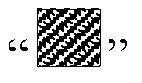
Fig.4 . - Furthermore, the aforesaid processing is multiplying the tail data block to be transmitted by the channel transmission matrix of the DL channel from the
unsynchronized BS 13 to theMS 2 and the precoding matrix of theunsynchronized BS 13, as well as the inverse matrix of the channel transmission matrix of the DL channel from thesynchronized BS 11 to theMS 2 and the inverse matrix of the precoding matrix of thesynchronized BS 11. - To be specific, assuming that DL data to be transmitted of the
unsynchronized BS 13 is S3, wherein the tail data block sent by thesynchronized BS 11 instead of theunsynchronized BS 13 is S31, the remaining data block is S32, wherein S3 = S31 + S32. - Before sending to the
MS 2 the tail data block S31 of theunsynchronized BS 13, thesynchronized BS 11 firstly processes the tail data block S31, that is, the tail data block S31 is transformed into

synchronized BS 11,
synchronized BS 11 to theMS 2, H 3 is the channel transmission matrix of the DL channel from theunsynchronized BS 13 to theMS 2, F 3 is the precoding matrix of theunsynchronized BS 13. - Because the
synchronized BS 11 sends the processed tail data block
MS 2, and theunsynchronized BS 13 sends to theMS 2 the remaining data S32 with the tail data block clipped, for theMS 2, the received data of theMS 2 is
unsynchronized BS 13. - Here, it is to be noted that, if the transmission manner of transmission diversity is used between BS and MS, the
synchronized BS 11 may send the processed tail data block of theunsynchronized BS 13 by using the antenna for sending its own DL data; but if the transmission manner of space multiplexing is used between BS and MS, thesynchronized BS 11 should use extra transmitting antenna to transmit the processed tail data block of theunsynchronized BS 13. - Hereinbefore, the scenario that when sending downlink data to the
MS 2, thesynchronized BS 11 processes part of data of theunsynchronized BS 12 and theunsynchronized BS 13 and sends the processed part of data to theMS 2 respectively at specific time slots simultaneously is described. - Hereinafter, referring to
Fig.2 andFig.5 , the scenarios that when sending DL data to theMS 2, theunsynchronized BS 12 processes part of data of theunsynchronized BS 13 and sends the processed part of data of theunsynchronized BS 13 to theMS 2 at specific time slots simultaneously, and when sending DL data to theMS 2, thesynchronized BS 13 processes part of data of theunsynchronized BS 12 and sends the processed part of data of theunsynchronized BS 12 to theMS 2 at specific time slots simultaneously are described. -
Fig.5 shows a schematic diagram of theunsynchronized BS 12 processing part of data of theunsynchronized BS 13 and sending the processed part of data of theunsynchronized BS 13 to theMS 2 at specific time slots simultaneously when sending DL data to theMS 2, and thesynchronized BS 13 processing part of data of theunsynchronized BS 12 and sending the processed part of data of theunsynchronized BS 12 to theMS 2 at specific time slots simultaneously when sending DL data to theMS 2. - In
Fig.5 , the first row corresponds to DL data from thesynchronized BS 11 that is received within the detection window of theMS 2 in the solution of the present invention. The upper portion of the second row corresponds to DL data from theunsynchronized BS 12 that is received within the detection window of theMS 2 in the solution of the prior art, the lower portion of the second row corresponds to DL data from theunsynchronized BS 12 that is received within the detection window of theMS 2 in the solution of the present invention. The upper portion of the third row corresponds to DL data from theunsynchronized BS 13 that is received within the detection window of theMS 2 in the solution of the prior art, the lower portion of the third row corresponds to DL data from theunsynchronized BS 13 that is received within the detection window of theMS 2 in the solution of the present invention. - For the
unsynchronized BS 12, firstly, theunsynchronized BS 12 receives backhaul information from theunsynchronized BS 13 via X2 interface. Wherein, backhaul message that is received from theunsynchronized BS 13 by theunsynchronized BS 12 comprises DL data to be transmitted from theunsynchronized BS 13 to theMS 2, the channel transmission matrix of DL channel from theunsynchronized BS 13 to theMS 2 and out-of-synchronization information of theunsynchronized BS 13 and theMS 2, namely propagation delay from theunsynchronized BS 13 to theMS 2. - Then, the
unsynchronized BS 12 determines whether out-of-synchronization information in backhaul information from theunsynchronized BS 13 is greater than 0. - Because the propagation distance from the
unsynchronized BS 13 to theMS 2 is less than the propagation distance from thesynchronized BS 11 to theMS 2, out-of-synchronization information corresponding to theunsynchronized BS 13 is less than 0. - Because out-of-synchronization information corresponding to the
unsynchronized BS 13 is less than 0, when sending DL data to theMS 2, theunsynchronized BS 12 processes tail data block corresponding to the length of the out-of-synchronization information in DL data sent by theunsynchronized BS 13 and sends the processed tail data block to theMS 2 at a specific time slot simultaneously. - Wherein, the specific time slot is the final time slot, lasting the length of the out-of-synchronization information, within the time slot occupied by the
synchronized BS 12 for sending DL data. - Accordingly, the
unsynchronized BS 13 postpones the transmission starting moment for the length of the out-of-synchronization information and sends to theMS 2 DL data to be transmitted with the tail data block corresponding to the length of the out-of-synchronization information clipped. - For example, if the out-of-synchronization information of the
unsynchronized BS 13 and theMS 2 is -0.1µs, then when sending DL data to theMS 2, theunsynchronized BS 12 processes tail data block corresponding to the length of 0.1µs in DL data sent by theunsynchronized BS 13 and sends the processed tail data block to theMS 2 at the final time slot of the length of 0.1µs for sending DL data simultaneously. - Accordingly, the
unsynchronized BS 13 postpones the transmission starting moment for the length of 0.1µs and then sends to theMS 2 DL data to be transmitted with the tail data block corresponding to the length of 0.1µs clipped. - It may be seen from
Fig. 5 that the upper portion of the third row corresponds to DL data from theunsynchronized BS 13 that received within the detection window of theMS 2 in the solution of the prior art, because of propagation delay such as -0.1µs between theunsynchronized BS 13 and theMS 2, data block (shown asin
Fig. 5 ) with the length of 0.1µs falls outside of the detection window of theMS 2 in the solution of the prior art. After using the solution of the present invention, because tail data block (shown asin
Fig. 5 ) corresponding to the length of 0.1µs in DL data sent by theunsynchronized BS 13 is sent by theunsynchronized BS 12 instead of theunsynchronized BS 13 at the final time slot of the length of 0.1µs for sending DL data simultaneously when thesynchronized BS 12 sends DL data, and theunsynchronized BS 13 postpones the transmission starting moment for the length of 0.1µs and then sends to theMS 2 DL data to be transmitted with tail data block corresponding to the length of 0.1µs clipped. Therefore, it may be seen from the solution of the present invention of the lower portion of the third row that DL data (namely DL data with tail data block corresponding to the length of 0.1µs clipped) that is received from theunsynchronized BS 13 by theMS 2 falls within detection window of theMS 2 completely. And the tail data block sent by theunsynchronized BS 12 instead of theunsynchronized BS 13 falls within the detection window of theMS 2, the tail data block being denoted bycorresponding to the lower portion of the second row in
Fig.5 . - Furthermore, the aforesaid processing is that the
unsynchronized BS 12 multiplies the tail data block to be transmitted by the channel transmission matrix of the DL channel from theunsynchronized BS 13 to theMS 2 and the precoding matrix of theunsynchronized BS 13, as well as the inverse matrix of the channel transmission matrix of the DL channel from theunsynchronized BS 12 to theMS 2 and the inverse matrix of the precoding matrix of theunsynchronized BS 12. - To be specific, assuming that DL data to be transmitted of the
unsynchronized BS 13 is S3, wherein the tail data block sent by theunsynchronized BS 12 instead of theunsynchronized BS 13 is S31, the remaining data block is S32, wherein S3 = S31 + S32. - Before sending to the
MS 2 the tail data block S31 of theunsynchronized BS 13, theunsynchronized BS 12 firstly processes the tail data block S31, that is, the tail data block S31 is transformed into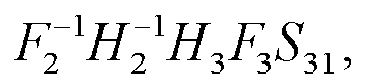

unsynchronized BS 12,
unsynchronized BS 12 to theMS 2, H 3 is the channel transmission matrix of the DL channel from theunsynchronized BS 13 to theMS 2, F 3 is the precoding matrix of theunsynchronized BS 13. - Because the
unsynchronized BS 12 sends the processed tail data block
MS 2, and theunsynchronized BS 13 sends to theMS 2 the remaining data S32 with the tail data block clipped, for theMS 2, the received data of theMS 2 is
unsynchronized BS 13. - Here, it is to be noted, if the transmission manner of transmission diversity is used between BS and MS, the
unsynchronized BS 12 may send the processed tail data block of theunsynchronized BS 13 by using the antenna for sending its own DL data; but if the transmission manner of space multiplexing is used between BS and MS, theunsynchronized BS 12 should use extra transmitting antenna to transmit the processed tail data block of theunsynchronized BS 13. - Similarly, for the
unsynchronized BS 13, firstly, theunsynchronized BS 13 receives backhaul information from theunsynchronized BS 12 via X2 interface. Wherein, backhaul information that is received from theunsynchronized BS 12 by theunsynchronized BS 13 comprises DL data to be transmitted from theunsynchronized BS 12 to theMS 2, the channel transmission matrix of DL channel from theunsynchronized BS 12 to theMS 2 and out-of-synchronization information of theunsynchronized BS 12 and theMS 2, namely propagation delay from theunsynchronized BS 12 to theMS 2. - Then, the
unsynchronized BS 13 determines whether out-of-synchronization information in backhaul information from theunsynchronized BS 12 is greater than 0. - Because the propagation distance from the
unsynchronized BS 12 to theMS 2 is greater than the propagation distance from thesynchronized BS 11 to theMS 2, out-of-synchronization information corresponding to theunsynchronized BS 12 is greater than 0. - Because out-of-synchronization information corresponding to the
unsynchronized BS 12 is greater than 0, when sending DL data to theMS 2, theunsynchronized BS 13 processes head data block corresponding to the length of the out-of-synchronization information in DL data sent by theunsynchronized BS 12 and sends the processed head data block to theMS 2 at a specific time slot simultaneously. - Wherein, the specific time slot is the start time slot, lasting the length of the out-of-synchronization information, within the time slot occupied by the
synchronized base station 13 for sending DL signal. - Accordingly, the
unsynchronized BS 12 sends to theMS 2 DL data to be transmitted with the head data block corresponding to the length of the out-of-synchronization information clipped. - For example, if the out-of-synchronization information of the
unsynchronized BS 12 and theMS 2 is 0.1µs, then when sending DL data to theMS 2, theunsynchronized BS 13 processes head data block corresponding to the length of 0.1µs in DL data sent by theunsynchronized BS 12 and sends the processed head data block to theMS 2 at the start time slot of the length of 0.1µs for sending DL data simultaneously. - Accordingly, the
unsynchronized BS 12 sends to theMS 2 DL data to be transmitted with the head data block corresponding to the length of 0.1µs clipped. - It may be seen from
Fig.5 that the upper portion of the second row corresponds to DL data from theunsynchronized BS 12 that is received within the detection window of theMS 2 in the solution of the prior art, because of propagation delay such as 0.1µs between theunsynchronized BS 12 and theMS 2, data block (shown asin
Fig. 5 ) with the length of 0.1µs falls outside of the detection window of theMS 2 in the solution of the prior art. After using the solution of the present invention, because head data block (shown asin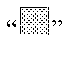
Fig. 5 ) corresponding to the length of 0.1µs in DL data sent by theunsynchronized BS 12 is sent by theunsynchronized BS 13 instead of theunsynchronized BS 12 at the start time slot of the length of 0.1µs for sending DL data simultaneously when theunsynchronized BS 13 sends DL data, and DL data that is sent to theMS 2 by theunsynchronized BS 12 is the DL data with head data block corresponding to the length of 0.1µs clipped. Therefore, it may be seen from the solution of the present invention of the lower portion of the second row that DL data (namely DL data with head data block corresponding to the length of 0.1µs clipped) that is received from theunsynchronized BS 12 by theMS 2 falls within the detection window of theMS 2 completely. And the head data block sent by theunsynchronized BS 13 instead of theunsynchronized BS 12 falls within the detection window of theMS 2, the head data block being denoted bycorresponding to the lower portion of the third row in
Fig.5 . - Furthermore, the aforesaid processing is that the
unsynchronized BS 13 multiplies the head data block to be transmitted by the channel transmission matrix of the DL channel from theunsynchronized BS 12 to theMS 2 and the precoding matrix of theunsynchronized BS 12, as well as the inverse matrix of the channel transmission matrix of the DL channel from theunsynchronized BS 13 to theMS 2 and the inverse matrix of the precoding matrix of theunsynchronized BS 13. - To be specific, assuming that DL data to be transmitted of the
unsynchronized BS 12 is S2, wherein the head data block sent by theunsynchronized BS 13 instead of theunsynchronized BS 12 is S21, the remaining data block is S22, wherein S2 = S21 + S22. - Before sending to the
MS 2 the head data block S21 of theunsynchronized BS 12, theunsynchronized BS 13 firstly processes the head data block S21, that is, the head data block S21 is transformed into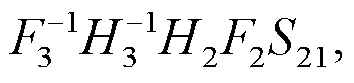

unsynchronized BS 13,
unsynchronized BS 13 to theMS 2, H 2 is the channel transmission matrix of the DL channel from theunsynchronized BS 12 to theMS 2, F 2 is the precoding matrix of theunsynchronized BS 12. - Because the
unsynchronized BS 13 sends the processed head data block
MS 2, and theunsynchronized BS 12 sends to theMS 2 the remaining data S22 with the head data block clipped, for theMS 2, the received data of theMS 2 is
unsynchronized BS 12. - Here, it is to be noted that, if the transmission manner of transmission diversity is used between BS and MS, the
unsynchronized BS 13 may send the processed head data block of theunsynchronized BS 12 by using the antenna for sending its own DL data; but if the transmission manner of space multiplexing is used between BS and MS, theunsynchronized BS 13 should use extra transmitting antenna to transmit the processed head data block of theunsynchronized BS 12. - In a variation shown in
Fig.6 , anunsynchronized BS 14 is included, and the propagation distance from theunsynchronized BS 14 to theMS 2 is greater than the propagation distance from theunsynchronized BS 12 to theMS 2. - Assuming that out-of-synchronization information corresponding to the
unsynchronized BS 12 is 0.1µs and out-of-synchronization information corresponding to theunsynchronized BS 14 is 0.2µs. it may be known from the aforesaid description of the solution of the present invention that the head data block corresponding to the length of 0.2µs in DL data to be transmitted of theunsynchronized BS 14 may be sent to theMS 2 at a specific time slot by thesynchronized BS 11 simultaneously when thesynchronized BS 11 sends DL data, and may also be sent to theMS 2 at a specific time slot by theunsynchronized BS 13 simultaneously when theunsynchronized BS 13 sends DL data. - Certainly, those skilled in the art may understand that the latter 0.1µs data block (shown asin

Fig.6 ) in the head data block corresponding to the length of 0.2µs may be sent to theMS 2 by theunsynchronized BS 12 at the start time slot of the length of 0.1µs for sending DL data simultaneously when theunsynchronized BS 12 sends DL data, and the former 0.1µs data block (shown asin
Fig.6 ) in the head data block corresponding to the length of 0.2µs may be sent to theMS 2 by thesynchronized BS 11 or theunsynchronized BS 13 at the start time slot of the length of 0.1µs for sending DL data simultaneously when thesynchronized BS 11 or theunsynchronized BS 13 sends DL data. - Hereinbefore, the solution of the present invention is described from the aspect of method; hereinafter the solution of the present invention will be further described from the aspect of device module.
- Hereinafter, referring to
Fig.2 ,Fig.4 andFig.7 , the scenario that when sending downlink data to theMS 2, acontrol device 100 in thesynchronized BS 11 processes part of data of theunsynchronized BS 12 and theunsynchronized BS 13 and sends the processed part of data to theMS 2 respectively at specific time slots simultaneously is described. The descriptions forFig.2 andFig.4 in the preceding context are taken as reference together. -
Fig.7 shows a block diagram of structure of acontrol device 100 in thesynchronized BS 11 for processing part of data of theunsynchronized BS 12 and theunsynchronized BS 13 and sending the processed part of data to theMS 2 at different time slots simultaneously, when sending downlink data to theMS 2, according to one embodiment of the present invention. - As shown in
Fig.7 , firstly, a first receiving means 1001 incontrol device 100 in thesynchronized BS 11 respectively receives backhaul information from theunsynchronized BS 12 and theunsynchronized BS 13 via X2 interface. Wherein, backhaul message that is received from theunsynchronized BS 12 by the first receiving means 1001 comprises DL data to be transmitted from theunsynchronized BS 12 to theMS 2, the channel transmission matrix of DL channel from theunsynchronized BS 12 to theMS 2 and out-of-synchronization information of theunsynchronized BS 12 and theMS 2, namely propagation delay from theunsynchronized BS 12 to theMS 2; backhaul message that is received from theunsynchronized BS 13 by the first receiving means 1001 comprises DL data to be transmitted from theunsynchronized BS 13 to theMS 2, the channel transmission matrix of DL channel from theunsynchronized BS 13 to theMS 2 and out-of-synchronization information of theunsynchronized BS 13 and theMS 2, namely propagation delay from theunsynchronized BS 13 to theMS 2. - Then, a first determining
means 1002 in thecontrol device 100 in thesynchronized BS 11 respectively determines whether out-of-synchronization information in backhaul information from theunsynchronized BS 12 and theunsynchronized BS 13 is greater than 0. - Because the
MS 2 and thesynchronized BS 11 achieve synchronization, out-of-synchronization information from thesynchronized BS 11 to theMS 2 is considered as 0. And because the propagation distance from theunsynchronized BS 12 to theMS 2 is greater than the propagation distance from thesynchronized BS 11 to theMS 2, out-of-synchronization information corresponding to theunsynchronized BS 12 is greater than 0; and because the propagation distance from theunsynchronized BS 13 to theMS 2 is less than the propagation distance from thesynchronized BS 11 to theMS 2, out-of-synchronization information corresponding to theunsynchronized BS 13 is less than 0. - Because out-of-synchronization information corresponding to the
unsynchronized BS 12 is greater than 0, when sending DL data to theMS 2, a first sending means 1003 in thecontrol device 100 in thesynchronized BS 11 processes head data block corresponding to the length of the out-of-synchronization information in DL data sent by theunsynchronized BS 12 and sends the processed head data block to theMS 2 at a specific time slot simultaneously. - Wherein, the specific time slot is the start time slot, lasting the length of the out-of-synchronization information, within the time slot occupied by the first sending means 1003 in the
synchronized base station 11 for sending DL data. - Accordingly, a fourth sending means in a first assisting control device in the
unsynchronized BS 12 sends to theMS 2 DL data to be transmitted with the head data block corresponding to the length of the out-of-synchronization information clipped. - For example, if the out-of-synchronization information of the
unsynchronized BS 12 and theMS 2 is 0.1µs, then when sending DL data to theMS 2, the first sending means 1003 in thesynchronized BS 11 processes head data block corresponding to the length of 0.1µs in DL data sent by theunsynchronized BS 12 and sends the processed head data block to theMS 2 at the start time slot of the length of 0.1µs for sending DL data simultaneously. - Accordingly, the fourth sending means in the first assisting control device in the
unsynchronized BS 12 sends to theMS 2 DL data to be transmitted with the head data block corresponding to the length of 0. 1µs clipped. - It may be seen from
Fig.4 that the upper portion of the second row corresponds to DL data from theunsynchronized BS 12 that is received within the detection window of theMS 2 in the solution of the prior art, because of propagation delay such as 0.1µs between theunsynchronized BS 12 and theMS 2, data block (shown asin
Fig. 4 ) with the length of 0.1µs falls outside of the detection window of theMS 2 in the solution of the prior art. After using the solution of the present invention, because head data block (shown asin
Fig. 4 ) corresponding to the length of 0.1µs in DL data sent by theunsynchronized BS 12 is sent by the first sending means 1003 in thesynchronized BS 11 instead of theunsynchronized BS 12 at the start time slot of the length of 0.1µs for sending DL data simultaneously when thesynchronized BS 11 sends DL data, and DL data that is sent to theMS 2 by the fourth sending means in the first assisting control device in theunsynchronized BS 12 is the DL data with head data block corresponding to the length of 0.1µs clipped. Therefore, it may be seen from the solution of the present invention of the lower portion of the second row that DL data (namely DL data with head data block corresponding to the length of 0.1µs clipped) that is received from theunsynchronized BS 12 by theMS 2 falls within the detection window of theMS 2 completely. And the head data block sent by the first sending means 1003 in thesynchronized BS 11 instead of theunsynchronized BS 12 falls within the detection window of theMS 2, the head data block being denoted bycorresponding to the first row in
Fig.4 . - Furthermore, the aforesaid processing is multiplying the head data block to be transmitted by the channel transmission matrix of the DL channel from the
unsynchronized BS 12 to theMS 2 and the precoding matrix of theunsynchronized BS 12, as well as the inverse matrix of the channel transmission matrix of the DL channel from thesynchronized BS 11 to theMS 2 and the inverse matrix of the precoding matrix of thesynchronized BS 11. - To be specific, assuming that DL data to be transmitted of the
unsynchronized BS 12 is S2, wherein the head data block sent by the first sending means 1003 in thesynchronized BS 11 instead of theunsynchronized BS 12 is S21, the remaining data block is S22, wherein S2 = S21 + S22. - Before sending to the
MS 2 the head data block S21 of theunsynchronized BS 12, the first sending means 1003 in thesynchronized BS 11 firstly processes the head data block S21, that is, the head data block S21 is transformed into

synchronized BS 11,
synchronized BS 11 to theMS 2, H 2 is the channel transmission matrix of the DL channel from theunsynchronized BS 12 to theMS 2, and F 2 is the precoding matrix of theunsynchronized BS 12. - Because the first sending means 1003 in the
synchronized BS 11 sends the processed head data block
MS 2, and the fourth sending means in a first assisting control device in theunsynchronized BS 12 sends to theMS 2 the remaining data S22 with the head data block clipped, for theMS 2, the received data of theMS 2 is
unsynchronized BS 12. - Here, it is to be noted that, if the transmission manner of transmission diversity is used between BS and MS, then the
synchronized BS 11 may send the processed head data block of theunsynchronized BS 12 by using the antenna for sending its own DL data; but if the transmission manner of space multiplexing is used between BS and MS, thesynchronized BS 11 should use extra transmitting antenna to transmit the processed head data block of theunsynchronized BS 12. - Similarly, Because out-of-synchronization information corresponding to the
unsynchronized BS 13 is less than 0, when sending DL data to theMS 2, the first sending means 1003 in thecontrol device 100 in thesynchronized BS 11 processes tail data block corresponding to the length of the out-of-synchronization information in DL data sent by theunsynchronized BS 13 and sends the processed tail data block to theMS 2 at a specific time slot simultaneously. - Wherein, the specific time slot is the final time slot, lasting the length of the out-of-synchronization information, within the time slot occupied by the first sending means 1003 in the
synchronized base station 11 for sending DL signal. - Accordingly, a fifth sending means in a second assisting control device in the
unsynchronized BS 13 postpones the transmission starting moment for the length of the out-of-synchronization information and then sends to theMS 2 DL data to be transmitted with the tail data block corresponding to the length of the out-of-synchronization information clipped. - For example, if the out-of-synchronization information of the
unsynchronized BS 13 and theMS 2 is -0.1µs, then when sending DL data to theMS 2, the first sending means 1003 in thesynchronized BS 11 processes tail data block corresponding to the length of 0.1µs in DL data sent by theunsynchronized BS 13 and sends the processed tail data block to theMS 2 at the final time slot of the length of 0.1µs for sending DL data simultaneously. - Accordingly, the fifth sending means in the second assisting control device in the
unsynchronized BS 13 postpones the transmission starting moment for the length of 0.1µs and then sends to theMS 2 DL data to be transmitted with the tail data block corresponding to the length of 0.1µs clipped. - It may be seen from
Fig.4 that the upper portion of the third row corresponds to DL data from theunsynchronized BS 13 that is received within the detection window of theMS 2 in the solution of the prior art, because of propagation delay such as -0.1µs between theunsynchronized BS 13 and theMS 2, data block (shown asin
Fig. 4 ) with the length of 0.1µs falls outside of the detection window of theMS 2 in the solution of the prior art. After using the solution of the present invention, because tail data block (shown asin
Fig. 4 ) corresponding to the length of 0.1µs in DL data sent by theunsynchronized BS 13 is sent by the first sending means 1003 in thesynchronized BS 11 instead of theunsynchronized BS 13 at the final time slot of the length of 0.1µs for sending DL data simultaneously when thesynchronized BS 11 sends DL data, and the fifth sending means in the second assisting control device in theunsynchronized BS 13 postpones the transmission starting moment for the length of 0.1µs and then sends to theMS 2 DL data to be transmitted with tail data block corresponding to the length of 0.1µs clipped. Therefore, it can be seen from the solution of the present invention of the lower portion of the third row that DL data (namely DL data with tail data block corresponding to the length of 0.1µs clipped) that is received from theunsynchronized BS 13 by theMS 2 falls within the detection window of theMS 2 completely. And the tail data block sent by the first sending means 1003 in thesynchronized BS 11 instead of theunsynchronized BS 13 falls within the detection window of theMS 2, the tail data block being denoted bycorresponding to the first row in
Fig.4 . - Furthermore, the aforesaid processing is multiplying the tail data block to be transmitted by the channel transmission matrix of the DL channel from the
unsynchronized BS 13 to theMS 2 and the precoding matrix of theunsynchronized BS 13, as well as the inverse matrix of the channel transmission matrix of the DL channel from thesynchronized BS 11 to theMS 2 and the inverse matrix of the precoding matrix of thesynchronized BS 11. - To be specific, assuming that DL data to be transmitted of the
unsynchronized BS 13 is S3, wherein the tail data block sent by the first sending means 1003 in thesynchronized BS 11 instead of theunsynchronized BS 13 is S31, the remaining data block is S32, wherein S3 = S31 + S32. - Before sending to the
MS 2 the tail data block S31 of theunsynchronized BS 13, the first sending means 1003 in thesynchronized BS 11 firstly processes the tail data block S31, that is, the tail data block S31 is transformed into

synchronized BS 11,
synchronized BS 11 to theMS 2, H 3 is the channel transmission matrix of the DL channel from theunsynchronized BS 13 to theMS 2, F 3 is the precoding matrix of theunsynchronized BS 13. - Because the first sending means 1003 in the
synchronized BS 11 sends the processed tail data block
MS 2, and the fifth sending means in the second assisting control device in theunsynchronized BS 13 sends to theMS 2 the remaining data S32 with the tail data block clipped, for theMS 2, the received data of theMS 2 is
unsynchronized BS 13. - Here, it is to be noted that, if the transmission manner of transmission diversity is used between BS and MS, the
synchronized BS 11 may send the processed tail data block of theunsynchronized BS 13 by using the antenna for sending its own DL data; but if the transmission manner of space multiplexing is used between BS and MS, thesynchronized BS 11 should use extra transmitting antenna to transmit the processed tail data block of theunsynchronized BS 13. - Hereinbefore, the scenario that when sending downlink data to the
MS 2, thecontrol device 100 in thesynchronized BS 11 processes part of data of theunsynchronized BS 12 and theunsynchronized BS 13 and sends the processed part of data to theMS 2 respectively at specific time slots simultaneously is described. - Hereinafter, referring to
Fig.2 andFig.5 , the scenarios that when sending DL data to theMS 2, theunsynchronized BS 12 processes part of data of theunsynchronized BS 13 and sends the processed part of data of theunsynchronized BS 13 to theMS 2 at specific time slots simultaneously, and when sending DL data to theMS 2, thesynchronized BS 13 processes part of data of theunsynchronized BS 12 and sends the processed part of data of theunsynchronized BS 12 to theMS 2 at specific time slots simultaneously are described. - The descriptions for
Fig.2 andFig.5 in the preceding contexts are taken as reference together. - For the
unsynchronized BS 12, firstly, a second receiving means in a control device in theunsynchronized BS 12 receives backhaul information from theunsynchronized BS 13 via X2 interface. Wherein, backhaul message that is received from theunsynchronized BS 13 by the second receiving means in the control device in theunsynchronized BS 12 comprises DL data to be transmitted from theunsynchronized BS 13 to theMS 2, the channel transmission matrix of DL channel from theunsynchronized BS 13 to theMS 2 and out-of-synchronization information of theunsynchronized BS 13 and theMS 2, namely propagation delay from theunsynchronized BS 13 to theMS 2. - Then, a second determining means in the control device in the
unsynchronized BS 12 determines whether out-of-synchronization information in backhaul information from theunsynchronized BS 13 is greater than 0. - Because the propagation distance from the
unsynchronized BS 13 to theMS 2 is less than the propagation distance from thesynchronized BS 11 to theMS 2, out-of-synchronization information corresponding to theunsynchronized BS 13 is less than 0. - Because out-of-synchronization information corresponding to the
unsynchronized BS 13 is less than 0, when sending DL data to theMS 2, a second sending means in the control device in theunsynchronized BS 12 processes tail data block corresponding to the length of the out-of-synchronization information in DL data sent by theunsynchronized BS 13 and sends the processed tail data block to theMS 2 at a specific time slot simultaneously. - Wherein, the specific time slot is the final time slot, lasting the length of the out-of-synchronization information, within the time slot occupied by the second sending means in the control device in the
synchronized BS 12 for sending DL data. - Accordingly, the fifth sending means in the second assisting control device in the
unsynchronized BS 13 postpones the transmission starting moment for the length of the out-of-synchronization information and sends to theMS 2 DL data to be transmitted with the tail data block corresponding to the length of the out-of-synchronization information clipped. - For example, if the out-of-synchronization information of the
unsynchronized BS 13 and theMS 2 is -0.1µs, then when sending DL data to theMS 2, the second sending means in the control device in theunsynchronized BS 12 processes tail data block corresponding to the length of 0.1µs in DL data sent by theunsynchronized BS 13 and sends the processed tail data block to theMS 2 at the final time slot of the length of 0.1µs for sending DL data simultaneously. - Accordingly, the fifth sending means in the second assisting control device in the
unsynchronized BS 13 postpones the transmission starting moment for the length of 0.1µs and then sends to theMS 2 DL data to be transmitted with the tail data block corresponding to the length of 0.1µs clipped. - It may be seen from
Fig.5 that the upper portion of the third row corresponds to DL data from theunsynchronized BS 13 that received within the detection window of theMS 2 in the solution of the prior art, because of propagation delay such as -0.1µs between theunsynchronized BS 13 and theMS 2, data block (shown asin
Fig. 5 ) with the length of 0.1µs falls outside of the detection window of theMS 2 in the solution of the prior art. After using the solution of the present invention, because tail data block (shown asin
Fig. 5 ) corresponding to the length of 0.1µs in DL data sent by theunsynchronized BS 13 is sent by the second sending means in the control device in theunsynchronized BS 12 instead of theunsynchronized BS 13 at the final time slot of the length of 0.1µs for sending DL data simultaneously when thesynchronized BS 12 sends DL data, and the fifth sending means in the second assisting control device in theunsynchronized BS 13 postpones the transmission starting moment for the length of 0.1µs and then sends to theMS 2 DL data to be transmitted with tail data block corresponding to the length of 0.1µs clipped. Therefore, it may be seen from the solution of the present invention of the lower portion of the third row that DL data (namely DL data with tail data block corresponding to the length of 0.1µs clipped) that is received from theunsynchronized BS 13 by theMS 2 falls within detection window of theMS 2 completely. And the tail data block sent by the second sending means in the control device in theunsynchronized BS 12 instead of theunsynchronized BS 13 falls within the detection window of theMS 2, the tail data block being denoted bycorresponding to the lower portion of the second row in
Fig.5 . - Furthermore, the aforesaid processing is that the second sending means in the control device in the
unsynchronized BS 12 multiplies the tail data block to be transmitted by the channel transmission matrix of the DL channel from theunsynchronized BS 13 to theMS 2 and the precoding matrix of theunsynchronized BS 13, as well as the inverse matrix of the channel transmission matrix of the DL channel from theunsynchronized BS 12 to theMS 2 and the inverse matrix of the precoding matrix of theunsynchronized BS 12. - To be specific, assuming that DL data to be transmitted of the
unsynchronized BS 13 is S3, wherein the tail data block sent by the second sending means in the control device in theunsynchronized BS 12 instead of theunsynchronized BS 13 is S31, the remaining data block is S32, wherein S3 = S31 + S32. Before sending to theMS 2 the tail data block S31 of theunsynchronized BS 13, the second sending means in the control device in theunsynchronized BS 12 firstly processes the tail data block S31, that is, the tail data block S31 is transformed into

unsynchronized BS 12,
unsynchronized BS 12 to theMS 2, H 3 is the channel transmission matrix of the DL channel from theunsynchronized BS 13 to theMS 2, F 3 is the precoding matrix of theunsynchronized BS 13. - Because the second sending means in the control device in the
unsynchronized BS 12 sends the processed tail data block
MS 2, and the fifth sending means in the second assisting control device in theunsynchronized BS 13 sends to theMS 2 the remaining data S32 with the tail data block clipped, for theMS 2, the received data of theMS 2 is
unsynchronized BS 13. - Here, it is to be noted, if the transmission manner of transmission diversity is used between BS and MS, the
unsynchronized BS 12 may send the processed tail data block of theunsynchronized BS 13 by using the antenna for sending its own DL data; but if the transmission manner of space multiplexing is used between BS and MS, theunsynchronized BS 12 should use extra transmitting antenna to transmit the processed tail data block of theunsynchronized BS 13. - Similarly, for the
unsynchronized BS 13, firstly, a third receiving means in the control device in theunsynchronized BS 13 receives backhaul information from theunsynchronized BS 12 via X2 interface. Wherein, backhaul information that is received from theunsynchronized BS 12 by the third receiving means in the control device in theunsynchronized BS 13 comprises DL data to be transmitted from theunsynchronized BS 12 to theMS 2, the channel transmission matrix of DL channel from theunsynchronized BS 12 to theMS 2 and out-of-synchronization information of theunsynchronized BS 12 and theMS 2, namely propagation delay from theunsynchronized BS 12 to theMS 2. - Then, a third determining means in the control device in the
unsynchronized BS 13 determines whether out-of-synchronization information in backhaul information from theunsynchronized BS 12 is greater than 0. - Because the propagation distance from the
unsynchronized BS 12 to theMS 2 is greater than the propagation distance from thesynchronized BS 11 to theMS 2, out-of-synchronization information corresponding to theunsynchronized BS 12 is greater than 0. - Because out-of-synchronization information corresponding to the
unsynchronized BS 12 is greater than 0, when sending DL data to theMS 2, a third sending means in the control device in theunsynchronized BS 13 processes head data block corresponding to the length of the out-of-synchronization information in DL data sent by theunsynchronized BS 12 and sends the processed head data block to theMS 2 at a specific time slot simultaneously. - Wherein, the specific time slot is the start time slot, lasting the length of the out-of-synchronization information, within the time slot occupied by the third sending means in the control device in the
synchronized base station 13 for sending DL signal. - Accordingly, the fourth sending means in the first assisting control device in the
unsynchronized BS 12 sends to theMS 2 DL data to be transmitted with the head data block corresponding to the length of the out-of-synchronization information clipped. - For example, if the out-of-synchronization information of the
unsynchronized BS 12 and theMS 2 is 0.1µs, then when sending DL data to theMS 2, the third sending means in the control device in theunsynchronized BS 13 processes head data block corresponding to the length of 0.1µs in DL data sent by theunsynchronized BS 12 and sends the processed head data block to theMS 2 at the start time slot of the length of 0.1µs for sending DL data simultaneously. - Accordingly, the fourth sending means in the first assisting control device in the
unsynchronized BS 12 sends to theMS 2 DL data to be transmitted with the head data block corresponding to the length of 0.1µs clipped. - It may be seen from
Fig.5 that the upper portion of the second row corresponds to DL data from theunsynchronized BS 12 that is received within the detection window of theMS 2 in the solution of the prior art, because of propagation delay such as 0.1µs between theunsynchronized BS 12 and theMS 2, data block (shown asin
Fig. 5 ) with the length of 0.1µs falls outside of the detection window of theMS 2 in the solution of the prior art. After using the solution of the present invention, because head data block (shown asin
Fig. 5 ) corresponding to the length of 0.1µs in DL data sent by theunsynchronized BS 12 is sent by the third sending means in the control device in theunsynchronized BS 13 instead of theunsynchronized BS 12 at the start time slot of the length of 0.1µs for sending DL data simultaneously when theunsynchronized BS 13 sends DL data, and DL data that is sent to theMS 2 by the fourth sending means in the first assisting control device in theunsynchronized BS 12 is the DL data with head data block corresponding to the length of 0.1µs clipped. Therefore, it may be seen from the solution of the present invention of the lower portion of the second row that DL data (namely DL data with head data block corresponding to the length of 0.1µs clipped) that is received from theunsynchronized BS 12 by theMS 2 falls within the detection window of theMS 2 completely. And the head data block sent by the third sending means in the control device in theunsynchronized BS 13 instead of theunsynchronized BS 12 falls within the detection window of theMS 2, the head data block being denoted bycorresponding to the lower portion of the third row in
Fig.5 . - Furthermore, the aforesaid processing is that the third sending means in the control device in the
unsynchronized BS 13 multiplies the head data block to be transmitted by the channel transmission matrix of the DL channel from theunsynchronized BS 12 to theMS 2 and the precoding matrix of theunsynchronized BS 12, as well as the inverse matrix of the channel transmission matrix of the DL channel from theunsynchronized BS 13 to theMS 2 and the inverse matrix of the precoding matrix of theunsynchronized BS 13. - To be specific, assuming that DL data to be transmitted of the
unsynchronized BS 12 is S2, wherein the head data block sent by the third sending means in the control device in theunsynchronized BS 13 instead of theunsynchronized BS 12 is S21, the remaining data block is S22, wherein S2 = S21 + S22. Before sending to theMS 2 the head data block S21 of theunsynchronized BS 12, the third sending means in the control device in theunsynchronized BS 13 firstly processes the head data block S21, that is, the head data block S21 is transformed into

unsynchronized BS 13,
unsynchronized BS 13 to theMS 2, H 2 is the channel transmission matrix of the DL channel from theunsynchronized BS 12 to theMS 2, F 2 is the precoding matrix of theunsynchronized BS 12. - Because the third sending means in the control device in the
unsynchronized BS 13 sends the processed head data block
MS 2, and the fourth sending means in the first assisting control device in theunsynchronized BS 12 sends to theMS 2 the remaining data S22 with the head data block clipped, for theMS 2, the received data of theMS 2 is
unsynchronized BS 12. - Here, it is to be noted that, if the transmission manner of transmission diversity is used between BS and MS, the
unsynchronized BS 13 may send the processed head data block of theunsynchronized BS 12 by using the antenna for sending its own DL data; but if the transmission manner of space multiplexing is used between BS and MS, theunsynchronized BS 13 should use extra transmitting antenna to transmit the processed head data block of theunsynchronized BS 12. - The detailed embodiments of the present invention are described hereinbefore, it needs to be understood that the present invention is not limited to the aforesaid specific embodiments, those skilled in the art may make all kinds of variation or modification within the scope of the appended claims.
Claims (18)
- A method of controlling propagation delay in a base station of a wireless communication system based on COMP transmission, the method comprising the steps of: when sending downlink data to a mobile station, processing part of data of one or more other unsynchronized base stations and sending the processed part of data to the mobile station at one or more specific time slots simultaneously.
- The method of claim 1, wherein when the base station is a synchronized base station, the method comprises the steps of:a. receiving one or more backhaul messages respectively from the one or more other unsynchronized base stations through X2 interface;b. determining whether out-of-synchronization information in each of the one or more backhaul messages is greater than 0 respectively;c. if out-of-synchronization information corresponding to an unsynchronized base station is greater than 0, then when sending downlink data to the mobile station, processing head data block corresponding to the length of the out-of-synchronization information in downlink data sent by the unsynchronized base station and sending the processed head data block to the mobile station at a specific time slot simultaneously,
wherein the specific time slot is the start time slot, lasting the length of the out-of-synchronization information, within the time slot occupied by the synchronized base station for sending downlink signal;d. if out-of-synchronization information corresponding to an unsynchronized base station is less than 0, then when sending downlink data to the mobile station, processing tail data block corresponding to the length of the out-of-synchronization information in downlink data sent by the unsynchronized base station and sending the processed tail data block to the mobile station at a specific time slot simultaneously,
wherein the specific time slot is the final time slot, lasting the length of the out-of-synchronization information, within the time slot occupied by the synchronized base station for sending downlink signal. - The method of claim 2, wherein the step of processing the head/tail data block comprises: multiplying the head/tail data block to be transmitted by the channel transmission matrix of the downlink channel from the unsynchronized base station to the mobile station and the precoding matrix of the unsynchronized base station, as well as the inverse matrix of the channel transmission matrix of the downlink channel from the synchronized base station to the mobile station and the inverse matrix of the precoding matrix of the synchronized base station.
- The method of claim 1, wherein when the base station is an unsynchronized base station and out-of-synchronization information corresponding to the unsynchronized base station is greater than 0, the method comprises the steps of:i. receiving one or more backhaul messages respectively from one or more other unsynchronized base stations through X2 interface;ii. determining whether out-of-synchronization information in each of the one or more backhaul messages is less than 0 respectively;iii. if out-of-synchronization information corresponding to an other unsynchronized base station is less than 0, then when sending downlink data to the mobile station, processing tail data block corresponding to the length of the out-of-synchronization information in downlink data sent by the other unsynchronized base station and sending the processed tail data block to the mobile station at a specific time slot,
wherein the specific time slot is the final time slot, lasting the length of the out-of-synchronization information, within the time slot occupied by the unsynchronized base station for sending downlink signal. - The method of claim 4, wherein the step of processing the tail data block comprises: multiplying the tail data block to be transmitted by the channel transmission matrix of the downlink channel from the other unsynchronized base station to the mobile station and the precoding matrix of the other unsynchronized base station, as well as the inverse matrix of the channel transmission matrix of the downlink channel from the unsynchronized base station to the mobile station and the inverse matrix of the precoding matrix of the unsynchronized base station.
- The method of claim 1, wherein when the base station is an unsynchronized base station and out-of-synchronization information corresponding to the unsynchronized base station is less than 0, the method comprises the steps of:i'. receiving one or more backhaul messages respectively from the one or more other synchronized base stations through X2 interface;ii'. determining whether out-of-synchronization information in each of the one or more backhaul messages is greater than 0 respectively;iii'. if out-of-synchronization information corresponding to an other unsynchronized base station is greater than 0, then when sending downlink data to the mobile station, processing head data block corresponding to the length of the out-of-synchronization information in downlink data sent by the other unsynchronized base station and sending the processed head data block to the mobile station at a specific time slot,wherein the specific time slot is the start time slot, lasting the length of the out-of-synchronization information, within the time slot occupied by the unsynchronized base station for sending downlink signal.
- The method of claim 6, wherein the step of processing the head data block comprises: multiplying the head data block to be transmitted by the channel transmission matrix of the downlink channel from the other unsynchronized base station to the mobile station and the precoding matrix of the other unsynchronized base station, as well as the inverse matrix of the channel transmission matrix of the downlink channel from the unsynchronized base station to the mobile station and the inverse matrix of the precoding matrix of the unsynchronized base station.
- A method of assisting to control propagation delay in an unsynchronized base station of a wireless communication system based on COMP transmission, wherein when out-of-synchronization information corresponding to the unsynchronized base station is larger than 0, the method comprises the steps of:- sending to a mobile station downlink data to be transmitted with head data block corresponding to the length of the out-of-synchronization information clipped.
- A method of assisting to control propagation delay in an unsynchronized base station of a wireless communication system based on COMP transmission, wherein when out-of-synchronization information corresponding to the unsynchronized base station is less than 0, the method comprises the steps of:- postponing transmission starting moment for the length of the out-of-synchronization information, and sending to a mobile station downlink data to be transmitted with tail data block corresponding to said length of the out-of-synchronization information clipped.
- A control device for controlling propagation delay in a base station of a wireless communication system based on COMP transmission, wherein the control device is used for processing part of data of one or more other unsynchronized base stations and sending the processed part of data to the mobile station at one or more specific time slots simultaneously, when sending downlink data to a mobile station.
- The control device of claim 10, wherein when the base station is a synchronized base station, the control device further comprises:a first receiving means, for receiving one or more backhaul messages respectively from the one or more other unsynchronized base stations through X2 interface;a first determining means, for determining whether out-of-synchronization information in each of the one or more backhaul messages is greater than 0 respectively;a first sending means, for processing head data block corresponding to the length of the out-of-synchronization information in downlink data sent by the unsynchronized base station and sending the processed head data block to the mobile station at a specific time slot simultaneously when sending downlink data to the mobile station, if out-of-synchronization information corresponding to an unsynchronized base station is greater than 0,wherein the specific time slot is the start time slot, lasting the length of the out-of-synchronization information, within the time slot occupied by the synchronized base station for sending downlink signal,the first sending means is further used for processing tail data block corresponding to the length of the out-of-synchronization information in downlink data sent by the unsynchronized base station and sending the processed tail data block to the mobile station at a specific time slot simultaneously when sending downlink data to the mobile station, if out-of-synchronization information corresponding to an unsynchronized base station is less than 0,wherein the specific time slot is the final time slot, lasting the length of the out-of-synchronization information, within the time slot occupied by the synchronized base station for sending downlink signal.
- The control device of claim 11, wherein the processing of the head/tail data block comprises: multiplying the head/tail data block to be transmitted by the channel transmission matrix of the downlink channel from the unsynchronized base station to the mobile station and the precoding matrix of the unsynchronized base station, as well as the inverse matrix of the channel transmission matrix of the downlink channel from the synchronized base station to the mobile station and the inverse matrix of the precoding matrix of the synchronized base station.
- The control device of claim 10, wherein when the base station is an unsynchronized base station and out-of-synchronization information corresponding to the unsynchronized base station is greater than 0, the control device comprises:a second receiving means, for receiving one or more backhaul messages respectively from one or more other unsynchronized base stations through X2 interface;a second determining means, for determining whether out-of-synchronization information in each of the one or more backhaul messages is less than 0 respectively;a second sending means, for processing tail data block corresponding to the length of the out-of-synchronization information in downlink data sent by the other unsynchronized base station and sending the processed tail data block to the mobile station at a specific time slot when sending downlink data to the mobile station, if out-of-synchronization information corresponding to an other unsynchronized base station is less than 0,wherein the specific time slot is the final time slot, lasting the length of the out-of-synchronization information, within the time slot occupied by the unsynchronized base station for sending downlink signal.
- The control device of claim 13, wherein the processing of the tail data block comprises: multiplying the tail data block to be transmitted by the channel transmission matrix of the downlink channel from the other unsynchronized base station to the mobile station and the precoding matrix of the other unsynchronized base station, as well as the inverse matrix of the channel transmission matrix of the downlink channel from the unsynchronized base station to the mobile station and the inverse matrix of the precoding matrix of the unsynchronized base station.
- The control device of claim 10, wherein when the base station is an unsynchronized base station and out-of-synchronization information corresponding to the unsynchronized base station is less than 0, the control device comprises:a third receiving means, for receiving one or more backhaul messages respectively from the one or more other synchronized base stations through X2 interface;a third determining means, for determining whether out-of-synchronization information in each of the one or more backhaul messages is greater than 0 respectively;a third sending means, for processing head data block corresponding to the length of the out-of-synchronization information in downlink data sent by the other unsynchronized base station and sending the processed head data block to the mobile station at a specific time slot when sending downlink data to the mobile station, if out-of-synchronization information corresponding to an other unsynchronized base station is greater than 0;wherein the specific time slot is the start time slot, lasting the length of the out-of-synchronization information, within the time slot occupied by the unsynchronized base station for sending downlink signal.
- The control device of claim 15, wherein the processing of the head data block comprises: multiplying the head data block to be transmitted by the channel transmission matrix of the downlink channel from the other unsynchronized base station to the mobile station and the precoding matrix of the other unsynchronized base station, as well as the inverse matrix of the channel transmission matrix of the downlink channel from the unsynchronized base station to the mobile station and the inverse matrix of the precoding matrix of the unsynchronized base station.
- A first assisting control device for assisting to control propagation delay in an unsynchronized base station of a wireless communication system based on COMP transmission, wherein when out-of-synchronization information corresponding to the unsynchronized base station is larger than 0, the first assisting control device comprises:a fourth sending means, for sending to a mobile station downlink data to be transmitted with head data block corresponding to the length of the out-of-synchronization information clipped.
- A second assisting control device for assisting to control propagation delay in an unsynchronized base station of a wireless communication system based on COMP transmission, wherein when out-of-synchronization information corresponding to the unsynchronized base station is less than 0, the second assisting control device comprises:a fifth sending means, for postponing transmission starting moment for the length of the out-of-synchronization information, and sending to a mobile station downlink data to be transmitted with tail data block corresponding to said length of the out-of-synchronization information clipped.
Applications Claiming Priority (2)
| Application Number | Priority Date | Filing Date | Title |
|---|---|---|---|
| CN2009100477471A CN101841361B (en) | 2009-03-18 | 2009-03-18 | Method and device for controlling transmission delay in cooperative multipoint transmission system |
| PCT/CN2010/071089 WO2010105556A1 (en) | 2009-03-18 | 2010-03-17 | Method and device for controlling transmission delay in a coordinated multi-point transmission system |
Publications (1)
| Publication Number | Publication Date |
|---|---|
| EP2410798A1 true EP2410798A1 (en) | 2012-01-25 |
Family
ID=42739206
Family Applications (1)
| Application Number | Title | Priority Date | Filing Date |
|---|---|---|---|
| EP10753123A Withdrawn EP2410798A1 (en) | 2009-03-18 | 2010-03-17 | Method and device for controlling transmission delay in a coordinated multi-point transmission system |
Country Status (7)
| Country | Link |
|---|---|
| US (1) | US20120014312A1 (en) |
| EP (1) | EP2410798A1 (en) |
| JP (1) | JP5260789B2 (en) |
| KR (1) | KR101337944B1 (en) |
| CN (1) | CN101841361B (en) |
| BR (1) | BRPI1009304A2 (en) |
| WO (1) | WO2010105556A1 (en) |
Cited By (1)
| Publication number | Priority date | Publication date | Assignee | Title |
|---|---|---|---|---|
| EP2800429A1 (en) * | 2013-05-03 | 2014-11-05 | Alcatel Lucent | Communication system comprising a plurality of communication nodes |
Families Citing this family (14)
| Publication number | Priority date | Publication date | Assignee | Title |
|---|---|---|---|---|
| CN102014216B (en) * | 2010-12-28 | 2013-06-12 | 中国科学院国家授时中心 | Method and device for detecting transmission delay of channels of public switched telephone network |
| CN102958084B (en) * | 2011-08-23 | 2018-03-02 | 中兴通讯股份有限公司 | The correcting method and system of a kind of delay inequality |
| CN102547968B (en) * | 2012-01-16 | 2014-09-10 | 电信科学技术研究院 | Coordinated multiple-point transmission downlink synchronization method and device |
| CN102685874B (en) * | 2012-04-12 | 2018-11-23 | 南京中兴新软件有限责任公司 | Deviation calibration mthods, systems and devices between a kind of multiple access points |
| CN103582151A (en) * | 2012-07-23 | 2014-02-12 | 中兴通讯股份有限公司 | Random access method and receiver |
| JP2016508341A (en) * | 2013-01-15 | 2016-03-17 | 富士通株式会社 | Negotiation method, apparatus and system for inter-base station function |
| CN105122878B (en) | 2013-04-23 | 2019-02-05 | 富士通株式会社 | Communication system, communication method, user terminal, control method and connection base station |
| WO2015139320A1 (en) * | 2014-03-21 | 2015-09-24 | 华为技术有限公司 | Method and apparatus for configuring position of frequency resource |
| CN109151920B (en) * | 2017-06-16 | 2021-07-20 | 成都鼎桥通信技术有限公司 | Method for transmitting synchronization signal and base station |
| US10820290B2 (en) | 2018-08-13 | 2020-10-27 | At&T Intellectual Property I, L.P. | Over the air synchronization by means of a protocol in a next generation wireless network |
| EP3874773B1 (en) | 2018-12-11 | 2025-11-05 | Zhejiang Dahua Technology Co., Ltd | Systems and methods for determining position and distance of a terminal |
| CN109714700B (en) * | 2018-12-11 | 2021-02-02 | 浙江大华技术股份有限公司 | Synchronization method, positioning method, main base station and positioning system |
| US11064449B2 (en) * | 2019-08-16 | 2021-07-13 | At&T Intellectual Property I, L.P. | Over the air synchronization of network nodes |
| CN111679247A (en) * | 2020-06-17 | 2020-09-18 | 广东博智林机器人有限公司 | Signal sending method and system, target positioning method, storage medium and processor |
Family Cites Families (11)
| Publication number | Priority date | Publication date | Assignee | Title |
|---|---|---|---|---|
| US6014376A (en) * | 1996-09-18 | 2000-01-11 | Motorola, Inc. | Method for over-the-air synchronization adjustment in a communication system |
| US6433739B1 (en) * | 1998-03-17 | 2002-08-13 | Qualcomm, Incorporated | Method and apparatus for synchronizing base stations using remote synchronizing stations |
| JP3376444B2 (en) * | 2000-07-07 | 2003-02-10 | 松下電器産業株式会社 | Base station apparatus and timing adjustment method for wireless communication system |
| GB0612139D0 (en) * | 2006-06-19 | 2006-08-02 | Nokia Corp | Synchronising wireless transmission of user data |
| US7701923B2 (en) * | 2006-07-10 | 2010-04-20 | Motorola, Inc. | Method and apparatus for frame synchronization in a communication network |
| CN101166073A (en) * | 2006-10-17 | 2008-04-23 | 株式会社Ntt都科摩 | A Cooperative Diversity Communication Method Applied to Multi-hop Communication System |
| US8149726B2 (en) * | 2007-01-04 | 2012-04-03 | Industrial Technology Research Institute | Wireless communication system and method |
| EP2012446A1 (en) * | 2007-07-06 | 2009-01-07 | Nokia Corporation | Higher layer synchronization between base stations |
| JP5147476B2 (en) * | 2008-03-17 | 2013-02-20 | 株式会社日立製作所 | Wireless communication system, base station, and data transmission timing control method |
| US8185060B2 (en) * | 2008-04-22 | 2012-05-22 | Qualcomm Incorporated | Serving base station selection using backhaul quality information |
| WO2010076854A1 (en) * | 2009-01-05 | 2010-07-08 | 富士通株式会社 | Communication device, mobile station, and communication control method |
-
2009
- 2009-03-18 CN CN2009100477471A patent/CN101841361B/en active Active
-
2010
- 2010-03-17 BR BRPI1009304A patent/BRPI1009304A2/en not_active IP Right Cessation
- 2010-03-17 KR KR1020117024164A patent/KR101337944B1/en not_active Expired - Fee Related
- 2010-03-17 EP EP10753123A patent/EP2410798A1/en not_active Withdrawn
- 2010-03-17 JP JP2012500050A patent/JP5260789B2/en not_active Expired - Fee Related
- 2010-03-17 US US13/257,110 patent/US20120014312A1/en not_active Abandoned
- 2010-03-17 WO PCT/CN2010/071089 patent/WO2010105556A1/en not_active Ceased
Non-Patent Citations (1)
| Title |
|---|
| See references of WO2010105556A1 * |
Cited By (1)
| Publication number | Priority date | Publication date | Assignee | Title |
|---|---|---|---|---|
| EP2800429A1 (en) * | 2013-05-03 | 2014-11-05 | Alcatel Lucent | Communication system comprising a plurality of communication nodes |
Also Published As
| Publication number | Publication date |
|---|---|
| CN101841361A (en) | 2010-09-22 |
| BRPI1009304A2 (en) | 2016-03-08 |
| US20120014312A1 (en) | 2012-01-19 |
| JP5260789B2 (en) | 2013-08-14 |
| JP2012521112A (en) | 2012-09-10 |
| KR20110129468A (en) | 2011-12-01 |
| WO2010105556A1 (en) | 2010-09-23 |
| CN101841361B (en) | 2012-11-07 |
| KR101337944B1 (en) | 2013-12-09 |
Similar Documents
| Publication | Publication Date | Title |
|---|---|---|
| EP2410798A1 (en) | Method and device for controlling transmission delay in a coordinated multi-point transmission system | |
| EP2445251B1 (en) | Transferring method, relay station and base station for uplink feedback information in relay link | |
| EP2343935B1 (en) | Method of uplink synchronization and related communication device | |
| JP5357984B2 (en) | Method and apparatus for avoiding interference caused by asynchronous in relay TDD system | |
| CN103313378B (en) | Timing method, timing reference determination method, device and system | |
| US8811239B2 (en) | Communication method and device | |
| CN103108389A (en) | Communication method and communication system from device to device and user devices | |
| TWI754040B (en) | Device and method of handling a measurement gap in a wireless communication system | |
| EP3175569B1 (en) | Cellular feedback transmission for user equipments enabling device-to-device communications | |
| KR101770906B1 (en) | Communication method and user equipment in mixed cellular and d2d network | |
| EP3780863B1 (en) | Communication method and device, apparatus, and storage medium | |
| US10044479B2 (en) | Method and apparatus for transmitting signal between user equipments | |
| CN101511115B (en) | Method and a device for determining if a handover has to be excuted for a terminal | |
| EP2015479A2 (en) | Subscriber station, time division multiplexing system and transmission timing control method suitable for wireless communication in synchronous PtoMP scheme | |
| CN118339791A (en) | HARQ feedback enhancements | |
| CN114342484B (en) | System information receiving method, sending method, device, terminal and storage medium | |
| CN103391611B (en) | Communication means, subscriber equipment, base station and communication equipment | |
| EP4443766A1 (en) | Network-assisted demodulation reference signal bundling framework | |
| CN103124191B (en) | Method and device of data transmission in mixed self-organizing network | |
| US8995408B2 (en) | Wireless base station and wireless communication method | |
| EP2110979A1 (en) | Communication network element and method transmitting data | |
| US20230269810A1 (en) | Method for resource updating, electronic device, and storage medium |
Legal Events
| Date | Code | Title | Description |
|---|---|---|---|
| PUAI | Public reference made under article 153(3) epc to a published international application that has entered the european phase |
Free format text: ORIGINAL CODE: 0009012 |
|
| 17P | Request for examination filed |
Effective date: 20111018 |
|
| AK | Designated contracting states |
Kind code of ref document: A1 Designated state(s): AT BE BG CH CY CZ DE DK EE ES FI FR GB GR HR HU IE IS IT LI LT LU LV MC MK MT NL NO PL PT RO SE SI SK SM TR |
|
| RAP1 | Party data changed (applicant data changed or rights of an application transferred) |
Owner name: ALCATEL LUCENT |
|
| DAX | Request for extension of the european patent (deleted) | ||
| 111Z | Information provided on other rights and legal means of execution |
Free format text: AT BE BG CH CY CZ DE DK EE ES FI FR GB GR HR HU IE IS IT LI LT LU LV MC MK MT NL NO PL PT RO SE SI SK SM TR Effective date: 20130410 |
|
| RAP1 | Party data changed (applicant data changed or rights of an application transferred) |
Owner name: ALCATEL LUCENT |
|
| D11X | Information provided on other rights and legal means of execution (deleted) | ||
| STAA | Information on the status of an ep patent application or granted ep patent |
Free format text: STATUS: THE APPLICATION IS DEEMED TO BE WITHDRAWN |
|
| 18D | Application deemed to be withdrawn |
Effective date: 20151001 |