EP2410725A1 - Receiver apparatus, transmitter apparatus, receiving method, transmitting method, communication system and communication method - Google Patents
Receiver apparatus, transmitter apparatus, receiving method, transmitting method, communication system and communication method Download PDFInfo
- Publication number
- EP2410725A1 EP2410725A1 EP09841868A EP09841868A EP2410725A1 EP 2410725 A1 EP2410725 A1 EP 2410725A1 EP 09841868 A EP09841868 A EP 09841868A EP 09841868 A EP09841868 A EP 09841868A EP 2410725 A1 EP2410725 A1 EP 2410725A1
- Authority
- EP
- European Patent Office
- Prior art keywords
- voice
- communication state
- unit
- audio data
- header compression
- Prior art date
- Legal status (The legal status is an assumption and is not a legal conclusion. Google has not performed a legal analysis and makes no representation as to the accuracy of the status listed.)
- Withdrawn
Links
Images














Classifications
-
- H—ELECTRICITY
- H04—ELECTRIC COMMUNICATION TECHNIQUE
- H04L—TRANSMISSION OF DIGITAL INFORMATION, e.g. TELEGRAPHIC COMMUNICATION
- H04L69/00—Network arrangements, protocols or services independent of the application payload and not provided for in the other groups of this subclass
- H04L69/04—Protocols for data compression, e.g. ROHC
-
- H—ELECTRICITY
- H04—ELECTRIC COMMUNICATION TECHNIQUE
- H04L—TRANSMISSION OF DIGITAL INFORMATION, e.g. TELEGRAPHIC COMMUNICATION
- H04L69/00—Network arrangements, protocols or services independent of the application payload and not provided for in the other groups of this subclass
- H04L69/22—Parsing or analysis of headers
-
- H—ELECTRICITY
- H03—ELECTRONIC CIRCUITRY
- H03M—CODING; DECODING; CODE CONVERSION IN GENERAL
- H03M7/00—Conversion of a code where information is represented by a given sequence or number of digits to a code where the same, similar or subset of information is represented by a different sequence or number of digits
- H03M7/30—Compression; Expansion; Suppression of unnecessary data, e.g. redundancy reduction
-
- H—ELECTRICITY
- H04—ELECTRIC COMMUNICATION TECHNIQUE
- H04L—TRANSMISSION OF DIGITAL INFORMATION, e.g. TELEGRAPHIC COMMUNICATION
- H04L1/00—Arrangements for detecting or preventing errors in the information received
- H04L1/12—Arrangements for detecting or preventing errors in the information received by using return channel
- H04L1/16—Arrangements for detecting or preventing errors in the information received by using return channel in which the return channel carries supervisory signals, e.g. repetition request signals
- H04L1/1607—Details of the supervisory signal
-
- H—ELECTRICITY
- H04—ELECTRIC COMMUNICATION TECHNIQUE
- H04L—TRANSMISSION OF DIGITAL INFORMATION, e.g. TELEGRAPHIC COMMUNICATION
- H04L65/00—Network arrangements, protocols or services for supporting real-time applications in data packet communication
- H04L65/60—Network streaming of media packets
- H04L65/65—Network streaming protocols, e.g. real-time transport protocol [RTP] or real-time control protocol [RTCP]
-
- H—ELECTRICITY
- H04—ELECTRIC COMMUNICATION TECHNIQUE
- H04W—WIRELESS COMMUNICATION NETWORKS
- H04W28/00—Network traffic management; Network resource management
- H04W28/02—Traffic management, e.g. flow control or congestion control
- H04W28/06—Optimizing the usage of the radio link, e.g. header compression, information sizing, discarding information
Definitions
- the present invention relates to a receiving apparatus, a transmitting apparatus, a receiving method, a transmitting method, a communications system, and a communication method that perform audio communication.
- LTE Long Term Evolution
- 3GPP 3rd Generation Partnership Project
- LTE systems realize high speed transmission in mobile communication, provide high speed service environments such as high speed image delivery, and are expected to facilitate efficient frequency utilization.
- Real-time data transmission in LTE systems similar to Voice over IP (VoIP) in typical wired IP networks, is implemented by RTP/UDP/IP protocols. Consequently, real-time data in LTE systems have large overhead due to the headers appended for each protocol.
- VoIP Voice over IP
- ROHC Robust Header Compressing
- PDCP Packet Data Convergence Protocol
- an object of the disclosed receiving apparatus, transmitting apparatus, receiving method, transmitting method, communications system and communication method is to improve the sound quality of audio data and improve band utilization efficiency.
- the receiving apparatus is a receiving apparatus in a communications system that performs header compression of audio data and has multiple operation modes that each have a different compression frequency.
- the receiving apparatus includes a receiving unit that receives the audio data transmitted by a transmitting apparatus, which performs the header compression; a determining unit that determines the voice-communication state of the audio data received by the receiving unit; and a control unit that changes the operation mode, according to a determination result obtained by the determining unit.
- the voice-communication state is determined and according to the voice-communication state, multiple operation modes, each having a different header compression frequency, can be switched between.
- the sound quality of audio data and band utilization efficiency can be improved.
- FIG. 1 is a block diagram of an example of configuration of a reception node according to a first embodiment.
- a reception node 100 depicted in FIG. 1 is an example of application of the receiving apparatus according to the embodiment, to user equipment (UE) such as a user terminal in an LTE system.
- the reception node 100 includes a MAC layer terminal unit 110, an RLC layer terminal unit 120, a PDCP terminal unit 130, an RTP/UDP/IP terminal unit 140, and an AMR terminal unit 150.
- the MAC layer terminal unit 110 is a terminus of a MAC layer in the communication with the transmission node (see FIG. 2 ). For example, the MAC layer terminal unit 110 corrects errors and controls retransmission of audio data or control data transmitted from the transmission node.
- the RLC layer terminal unit 120 is a terminus of an RLC layer in the communication with the transmission node.
- the PDCP terminal unit 130 is a terminus of a PDCP layer in the communication with the transmission node. Further, the PDCP terminal unit 130 is a terminus of the ROHC layer in the communication with the transmission node.
- the PDCP terminal unit 130 includes a reception buffer 131, a reception processing unit 132, an expanding unit 133, a voice-communication state determining unit 134, an ROHC control unit 135, and a transmission processing unit 136.
- the reception buffer 131 temporarily stores PDCP_PDU received through the MAC layer terminal unit 110 and the RLC layer terminal unit 120.
- the reception processing unit 132 (receiving unit) reads out the PDCP_PDU stored in the reception buffer 131, performs header processing on the PDCP_PDU, and outputs the PDCP_PDU to the expanding unit 133.
- the PDCP_PDU readout by the reception processing unit 132 is erased from the reception buffer 131.
- the expanding unit 133 expands the ROHC header of the data output from the reception processing unit 132 and outputs the data to the RTP/UDP/IP terminal unit 140.
- the expanding unit 133 expands the ROHC header according to the operation mode, which is changed by the ROHC control unit 135.
- the voice-communication state determining unit 134 determines the voice-communication state of the audio data received by the reception node 100 from the transmission node and notifies the ROHC control unit 135 of the determination results.
- a voice-communication state is, for example, a state related to whether the audio of the audio data is "sound" or "silence".
- the voice-communication state determining unit 134 determines the voice-communication state, based on the volume of accumulated data in the reception buffer 131.
- the voice-communication state determining unit 134 determines the voice-communication state to be "sound"
- the voice-communication state determining unit 134 determines the voice-communication state to be "silence”
- the threshold to which the volume of accumulated data is compared is, for example, a value corresponding to the size of silence insertion descriptor (SID) data transmitted from the transmission node when the voice-communication state is "silence”.
- the ROHC control unit 135 (control unit) changes the ROHC operation mode in the reception node 100 and transmission node, according to the determination results output from the voice-communication state determining unit 134. For example, the ROHC control unit 135 changes the ROHC operation mode in the reception node 100 and transmission node to any one among a U-mode, an O-mode, and an R-mode. These ROHC operations are described hereinafter (refer to FIGS. 5 to 8 ).
- the ROHC control unit 135 To change the ROHC operation mode, the ROHC control unit 135 generates a change instructing signal that indicates the operation mode to be changed to. The ROHC control unit 135 outputs the generated change instructing signal to the transmission processing unit 136. Consequently, the change instructing signal is transmitted to the transmission node and the ROHC mode is changed.
- the transmission processing unit 136 appends PDCP_PDU headers. For example, the transmission processing unit 136 appends headers to the change instructing signal output from the ROHC control unit 135 and outputs the change instructing signal to the transmission node through the MAC layer terminal unit 110 and the RLC layer terminal unit 120.
- the RTP/UDP/IP terminal unit 140 is a terminus of an RTP/UDP/IP layer in the communication with the transmission node.
- the AMR terminal unit 150 is a terminus of an AMR layer in the communication with the transmission node. For example, the AMR terminal unit 150 decodes audio data received from the transmission node.
- the reception node 100 may have a function related to an uplink of audio data transmitted by the reception node 100 (UE) to the transmission node (eNB).
- the voice-communication state determining unit 134 depicted in FIG. 1 writes the results of the voice-communication state determination to memory (not depicted) of the reception node 100.
- the voice-communication state determining unit 134 for example, is a computing unit such as a central processing unit (CPU).
- the ROHC control unit 135 reads the determination results written to the memory of the reception node 100 by the voice-communication state determining unit 134 and according to the read determination results, changes the ROHC operation mode.
- the ROHC control unit 135 is, for example, a computing unit such as a CPU.
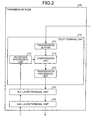
- FIG. 2 is a block diagram of an example of configuration of the transmission node according to the first embodiment.
- a transmission node 200 depicted in FIG. 2 is an example of application of the transmitting apparatus according to the embodiment, to an eNB in the LTE system.
- the transmission node 200 includes a PDCP terminal unit 210, an RLC layer terminal unit 220, and a MAC layer terminal unit 230.
- the PDCP terminal unit 210 is a terminus of the PDCP layer in the communication with the reception node 100.
- the PDCP terminal unit 210 is further a terminus of the ROHC layer in the communication with the reception node 100.
- the PDCP terminal unit 210 includes a transmission buffer 211, a compressing unit 212, a transmission processing unit 213, and a reception processing unit 214.
- the transmission buffer 211 temporarily stores PDCP_SDU transmitted from an upper system (e.g., S-GW_IF) of the transmission node 200.
- the compressing unit 212 reads out the PDCP_SDU stored in the transmission buffer 211, compresses the header, and outputs the PDCP_SDU to the transmission processing unit 213.
- the PDCP_SDU read out by the compressing unit 212 is deleted from the transmission buffer 211. Further, the compressing unit 212 compresses the header according to the ROHC operation mode set in the transmission node 200. For example, the compressing unit 212 acquires from the reception processing unit 214, the change instructing signal for the ROHC operation mode, received from the reception node 100, and compresses the header according to the operation mode indicated by the change instructing signal.
- the transmission processing unit 213 appends a PDCP header to the PDCP_SDU output from the compressing unit 212 and outputs the resulting PDCP_SDU as a PDCP_PDU to the reception node 100, through the RLC layer terminal unit 220 and the MAC layer terminal unit 230.
- the reception processing unit 214 processes the header of a PDCP_PDU received from the reception node 100 through the RLC layer terminal unit 220 and the MAC layer terminal unit 230.
- the reception processing unit 214 processes the header of a change instructing signal received from the reception node 100 and outputs the change instructing signal to the compressing unit 212.
- the RLC layer terminal unit 220 is a terminus of the RLC layer in the communication with the reception node 100.
- the MAC layer terminal unit 230 is a terminus of the MAC layer in the communication with the reception node 100.
- the transmission node 200 may have a function related to an uplink of audio data transmitted by the reception node 100 (UE) to the transmission node 200 (eNB).
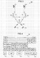
- FIG. 3 is a diagram of an example of configuration of a communications system according to the first embodiment.
- a communications system 300 depicted in FIG. 3 is an example of application of the communications system according to the embodiment, to an LTE system.
- the communications system 300 includes MME/S-GWs 311, 312; eNBs 321-323; and UE 331, 332.
- the MME/S-GWs 311, 312 respectively include a mobility management entity (MME) function and a serving gateway (S-GW) function in the LTE system.
- MME mobility management entity
- S-GW serving gateway
- the MME/S-GWs 311, 312 are respectively connected to the eNBs 321-323 by an S1 interface.
- the eNBs 321-323 are respectively an LTE system E-UTRAN_NodeB and are connected by an X2 interface. Further, the eNBs 321-323 respectively perform audio communication with each of the UE 331, 332 by wireless communication.
- the UE 331, 332 are respectively mobile terminals such as a mobile telephone.
- the reception node 100 depicted in FIG. 1 can be applied to at least one of the UE 331, 332.
- the transmission node 200 depicted in FIG. 2 can be applied to at least one of the eNBs 321-323.
- reception node 100 depicted in FIG. 1 may be applied to at least one of the eNBs 321-323; and the transmission node 200 depicted in FIG. 2 may be applied to at least one of the UE 331, 332.
- the PDCP terminal unit 130 of the reception node 100 depicted in FIG. 1 is connected to an upper system (e.g., S-GW_IF) and the transmission node 200 depicted in FIG. 2 includes the RTP/UDP/IP terminal unit 140 and the AMR terminal unit 150 (see FIG. 1 ).
- FIG. 4 is a diagram of a protocol stack in the communications system depicted in FIG. 3 .
- a protocol stack 400 depicted in FIG. 4 is applied.
- the protocol stack 400 depicted in FIG. 4 is a protocol stack related to IP-based real-time data, such as in audio communications, and under investigation under LTE.
- UE 411 is the UE 331, 332 depicted in FIG. 3 .
- eNB 412 is the eNBs 321-323 depicted in FIG. 3 .
- S-GW 413 is the MME/S-GWs 311, 312 depicted in FIG. 3 .
- PDN-GW 414 and an IP network 415 are connected to the MME/S-GWs 311, 312 depicted in FIG. 3 .
- PHY and Ether represent a physical layer (Physical) and an Ethernet (registered trademark), respectively.
- PHY and “Ether” use interfaces compliant as a basic rate interface of a local area network (LAN) and of a wide area network (WAN).
- LAN local area network
- WAN wide area network
- IP Internet Protocol
- UDP User Datagram Protocol
- RTP Real-time Transport Protocol
- RTP uses application-specific profiles and payload formats.
- GTP-U GPRS Tunneling Protocol tunnels user data in LTE/SAE networks.
- MAC Medium Access Control performs scheduling, priority control, error correction by Hybrid Automatic Repeat Request (HARQ), selection of transformat, etc.
- RLC Radio Link Control
- PDCP Packet Data Convergence Protocol
- ROHC header compression
- the RTP/UDP/IP header is compressed by ROHC, a function of the PDCP terminated in the eNB 412.
- AMR audio data
- the header is expanded by ROHC and the original audio data is recovered.
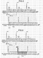
- FIG. 5 is a diagram of U-mode operation of ROHC (part 1).
- the horizontal axis represents time.
- An example will be described where at the RTP/UDP/IP layer, the transmission node 200 transmits audio data to the reception node 100 by a 20[msec]-cycle frame.
- An uncompressed frame 511 is audio data (including context) transmitted by the transmission node 200, without header compression.
- a compressed frame 512 is audio data (including context) that has a compressed header and is transmitted by the transmission node 200.
- a dimension along a direction perpendicular to the horizontal axis of the uncompressed frame 511 and the compressed frame 512 indicates frame size. Since the header has been compressed, the size of the compressed frame 512 is smaller than that of the uncompressed frame 511 whose header has not been compressed.
- the ROHC operation mode for the reception node 100 and the transmission node 200 is the U-mode (Unidirectional Mode).
- the transmission node 200 transmits a frame every 20[msec] and among the transmitted frames, frames transmitted at 180[msec] intervals are regarded as an uncompressed frame 511 while other frames are regarded as compressed frames 512.
- the reception node 100 receives the frames while expanding (recovering) the headers of the compressed frames 512, based on the context included in the previously received uncompressed frame 511. For example, based on the context included in the uncompressed frame 511 received at period t521, the reception node 100 expands the header of the compressed frames 512 received during interval T522 immediately subsequent to period t521.
- the transmission node transmits context at given intervals, whereby communication quality is assured.
- feedback requesting context the uncompressed frame 5111 from the reception node 100 is performed, whereby band of the link from the reception node 100 to the transmission node 200 is not under pressure.
- FIG. 6 is a diagram of U-mode operation of ROHC (part 2).
- parts identical to those depicted in FIG. 5 are given the same reference numerals used in FIG. 5 and description thereof is omitted.
- the operation mode of ROHC is the U-mode (see FIG. 5 ) and that at period t611, an uncompressed frame 511 is properly received by the reception node 100.
- the interval during which the compressed frames 512 result in data loss continues until the reception node 100 subsequently receives the uncompressed frame 511 and the context is recovered. Consequently, the interval during which the compressed frames 512 result in data loss is dependent upon the cycle (here, 180[msec]) at which the transmission node 200 transmits the context (the uncompressed frame 511).
- FIG. 7 is a diagram of the O-mode operation of ROHC.
- the ROHC operation mode of the reception node 100 and the transmission node 200 is set as the O-mode (Bidirectional Optimistic Mode).
- the transmission node 200 transmits, as an uncompressed frame 511, a frame whose header contents is different from that of the previous frame and transmits other frames as compressed frames 512.
- the reception node 100 receives the frames while expanding (recovering) the headers of the compressed frames 512, based on the context included in the previously received uncompressed frame 511.
- the reception node 100 transmits a Nack to the transmission node 200. For example, at period t711, if the reception node 100 is unable to properly receive the uncompressed frame 511, at period t712, which is immediately subsequent to period t711, the reception node 100 transmits a Nack 701 to the transmission node 200.
- the transmission node 200 Upon receiving the Nack 701 from the reception node 100, the transmission node 200 retransmits the uncompressed frame 511.
- the reception node 100 receives the retransmitted uncompressed frame 511 at period t713, subsequent to period t712.
- the interval during which the compressed frames 512 result in data loss continues until the reception node 100 subsequently receives the uncompressed frame 511 and the context is recovered. Consequently, the interval during which the compressed frames 512 result in data loss is dependent on the period from time that the reception node 100 transmits a Nack to the transmission node 200 until the transmission node 200 retransmits the uncompressed frame 511 to the reception node 100.
- Context (the uncompressed frame 511) is transmitted if the reception node 100 could not properly receive a frame, whereby the transmission frequency of the compressed frame 512 is high and header compression efficiency is favorable.
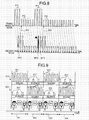
- FIG. 8 is a diagram of R-mode operation of ROHC.
- the ROHC operation mode of the reception node 100 and the transmission node 200 is set as the R-mode (Bidirectional Reliable Mode).
- the transmission node 200 transmits an uncompressed frame 511 every 20[msec] and upon receiving, from the reception node 100, an Ack for the uncompressed frame 511, the transmission node 200 subsequently transmits compressed frames 512 until there is a change in the header contents.
- the reception node 100 If the reception node 100 properly receives the uncompressed frames 511, the reception node 100 transmits an Ack to the transmission node 200. For example, it is assumed that at period t811, the reception node 100 properly receives the uncompressed frame 511 and transmits an Ack 801 to the transmission node 200. Upon receiving the Ack 801 from the reception node 100, the transmission node 200 transmits compressed frames 512 until there is a change in the header contents.
- the reception node 100 cannot properly receive the uncompressed frame 511.
- the reception node 100 properly receives the uncompressed frame 511 and transmits an Ack 802 to the transmission node 200.
- the transmission node 200 transmits the uncompressed frame 511 and upon receiving the Ack 802 from the reception node 100, the transmission node 200 subsequently transmits compressed frames 512 until there is a change in the header contents.
- the transmission node 200 upon receiving an Ack indicating that the context has properly reached the reception node 100, the transmission node 200 begins compressing the headers. Consequently, as compared to the U-mode and the O-mode, header compression efficiency is lower for the ROHC R-mode, but the reliability of context consistency is favorable. Furthermore, periods of data loss accompanying the inability to expand headers after context loss, do not occur.
- Switching between the ROHC operations depicted in FIGS. 5 to 8 is performed by the transmission of a change instructing signal from the reception node 100 to the transmission node 200.
- An example of switching between the ROHC operation modes will be described hereinafter (see FIGS. 34 to 36 ).
- FIG. 9 is a diagram of an example of a change in the voice-communication state.
- the horizontal axis represents time.
- Reference 910 represents audio data transmitted from the transmission node 200 to the reception node 100.
- Reference numeral 920 represents audio data transmitted from the reception node 100 to the transmission node 200.
- Person A represents a user on the transmission node 200 side.
- Person B represents a user on the reception node 100 side.
- AMR data 911 is transmitted when audio is to be transmitted.
- SID data 912 is transmitted when there is no audio to be transmitted.
- a dimension along a direction perpendicular to the horizontal axis of the AMR data 911 and the SID data 912 indicates data size. As depicted in FIG. 9 , the size of the SID data 912 is smaller than that of the AMR data 911.
- Intervals 931-934 are temporally continuous intervals of time.
- the voice-communication state of the audio data (reference numeral 910) transmitted from the transmission node 200 to the reception node 100 is "sound" in the intervals 931 and 933; and is "silence” in the intervals 932 and 934.
- the voice-communication state of the audio data (reference numeral 920) transmitted from the reception node 100 to the transmission node 200 is "silence” in the intervals 931 and 933; and is "sound” in the intervals 932 and 934.
- the reception node 100 and the transmission node 200 determine the voice-communication state of the audio data and change the ROHC operation state according to the determined voice-communication state. Consequently, when the voice-communication state is "sound”, the quality can be improved and when the voice-communication state is "silence", efficient header compression can be facilitated.
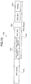
- FIG. 10 is a diagram of an example of MAC_PDU.
- the MAC layer frame format of the audio data transmitted and received between the reception node 100 and the transmission node 200 is, for example, a MAC_PDU 1000 depicted in FIG. 10 .
- the MAC_PDU 1000 is a MAC frame format at a layer below PDCP in the LTE system.
- the MAC_PDU 1000 includes a MAC_Header 1010 and a MAC_Payload 102.
- the MAC_Payload 1020 includes a MAC_Control_Element 1021 (see FIG. 11 ), a MAC_SDU 1022, and padding 1023.
- FIG. 11 is a diagram of the MAC_Control_Elements depicted in FIG. 10 .
- a table 1100 depicted in FIG. 11 depicts the types of the MAC_Control_Elements 1021 depicted in FIG. 10 .
- the MAC_Control_Element 1021 type field includes "UE Contention Resolution Identity”, “Timing Advance”, and "DRX Command".
- the MAC_Control_Element 1021 type field includes "Power Headroom Report”, "C-RNTI”, “Short_BSR”, and "Long_BSR”.
- Short_BSR indicates the volume of accumulated data in the buffer. Therefore, by the "Short_BSR” or the “Long_BSR” included in the MAC_Control_Element 1021, the transmission node 200 can notify the reception node 100 of the volume of accumulated data in the transmission buffer 211.
- FIG. 12 is a diagram of the Short_BSR depicted in FIG. 11 .
- the frame format of the "Short_BSR" depicted in FIG. 11 is, for example, a Short_BSR 1200 depicted in FIG. 12 .
- the Short_BSR 1200 includes an LCG_ID 1210 (Logical Channel Group) and buffer size 1220.
- the LCG_ID 1210 is an ID of a logical channel group (e.g., logical channel groups #1-#4).
- the buffer size 1220 indicates the total volume of accumulated data for the logical channel group of the LCG_ID 1210. An example of the buffer size 1220 will be described hereinafter (see FIG. 14 ).
- FIG. 13 is a diagram of the Long_BSR depicted in FIG. 11 .
- the frame format of the "Long_BSR" depicted in FIG. 11 is, for example, a Long_BSR 1300 depicted in FIG. 13 .
- the Long_BSR 1300 includes buffer sizes #1-#4.
- the buffer sizes #1-#4 indicate the total volume of accumulated data for each UE. An example of the buffer sizes #1-#4 will be described hereinafter (see FIG. 14 ).
- FIG. 14 is a diagram of a buffer size index.
- the buffer size 1220 depicted in FIG. 12 or the buffer sizes #1-#4 depicted in FIG. 13 , for example, are indicated by an index based on a table 1400 depicted in FIG. 14 .
- a buffer size (BS) of 0[Bytes] is indicated by an index "0".
- a buffer size that is greater than 0[Bytes] and equal to or less than 10[Bytes] is indicated by an index "1". Further, a buffer size that is greater than 10[Bytes] and equal to or less than 12[Bytes] is indicated by an index "2". In this manner, by indicating buffer size, which indicates data-volume information by an index, the size of the data-volume information can be made small.
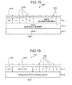
- FIG. 15 is a diagram of a data PDU format.
- the PDCP header frame format of the data PDU transmitted and received between the reception node 100 and the transmission node 200 is, for example, a PDCP frame 1500 depicted in FIG. 15 .
- the PDCP frame 1500 includes D/C 1510, R 1520 (Reserved), a PDCP sequence number 1530, and data 1540.
- the D/C 1510 is a value indicting whether the PDCP frame 1500 is a data PDU or a control PDU. In the PDCP frame 1500, the D/C 1510 is "1" indicative of data PDU.
- the R 1520 is not used in herein.
- the PDCP sequence number 1530 is the PDCP frame 1500 sequence number.
- the data 1540 is, for example, the AMR data 911 or the SID data 912.
- FIG. 16 is a diagram of an example of control PDU format.
- parts identical to those depicted in FIG. 15 are given the same reference numerals used in FIG. 15 and description thereof is omitted.
- the PDCP header of control PDU transmitted and received between the reception node 100 and the transmission node 200 are, for example, a PDCP frame 1600 depicted in FIG. 16 .
- the PDCP frame 1600 includes D/C 1510, PDU type 1610, R 1520, and an Interspersed_ROHC_feedback_packet 1620.
- the D/C 1510 is "0" indicative of control PDU.
- the PDU type 1610 indicates the type of control PDU (PDCP status report, header compression feedback information, etc.).
- FIG. 17 is a flowchart of an example of operation of the reception node depicted in FIG. 1 .
- the reception node 100 depicted in FIG. 1 performs the steps depicted in FIG. 17 .
- the voice-communication state determining unit 134 of the reception node 100 determines the voice-communication state ("sound" or "silence") of the audio data that the reception node 100 received from the transmission node 200 (step S1701).
- the voice-communication state determining unit 134 determines whether the voice-communication state determined at step S1701 has changed from the voice-communication state that was previously determined by the voice-communication state determining unit 134 (step S1702). If the voice-communication state has not changed (step S1702: NO), the reception node 100 returns to step S1701 and continues processing therefrom.
- step S1702 if the voice-communication state has changed (step S1702: YES), the ROHC control unit 135 changes the ROHC operation mode according to the voice-communication state determined at step S1701 (step S1703), ending a series of operations. If the voice-communication state is "silence", at step S1703, the ROHC control unit 135 changes the ROHC operation mode to, for example, the U-mode which has high header compression frequency.
- the ROHC control unit 135 changes the ROHC operation mode to, for example, the O-mode or the R-mode, which have low header compression frequencies. Consequently, when the voice-communication state is "sound", sound quality can be improved and when the voice-communication state is "silence" efficient header compression can be facilitated.
- FIG. 18 is a flowchart of step S1701 depicted in FIG. 17 .
- the voice-communication state determining unit 134 executes the following steps.
- the voice-communication state determining unit 134 determines whether the time that has elapsed since the start of operation has become at least equal to a monitoring cycle (e.g., 20[msec]) (step S1801), and waits until the elapsed time is equal to or greater than the monitoring cycle (step S1801: NO).
- a monitoring cycle e.g. 20[msec]
- step S1801 when the elapsed time has become equal to or greater than the monitoring cycle (step S1801: YES), the voice-communication state determining unit 134 measures the volume of accumulated data in the reception buffer 131 (step S1802) and determines whether the voice-communication state previously determined by the voice-communication state determining unit 134 and stored in memory is "sound" (step S1803).
- step S1803 if the voice-communication state is "sound" (step S1803: YES), the voice-communication state determining unit 134 determines whether the volume of accumulated data measured at step S1802 is at most a threshold (step S1804). If the volume of accumulated data is not less than or equal to the threshold (step S1804: NO), the series of processes ends.
- step S1804 if the volume of accumulated data measured at step S1802 is less than or equal to the threshold (step S1804: YES), the voice-communication state stored in the memory is updated to "silence" (step S1805), ending the series of the processes.
- step S1803 if the voice-communication state is not "sound" (step S1803: NO), the voice-communication state determining unit 134 determines whether the volume of accumulated data measured at step S1802 is greater than a threshold (step S1806). If the volume of accumulated data is not greater than the threshold (step S1806: NO), the series of processes ends.
- step S1806 if the volume of accumulated data measured at step S1802 is greater than the threshold (step S1806: YES), the voice-communication state stored in the memory is updated to "sound" (step S1807), ending the series of processes.
- the thresholds used for comparison for example, correspond to the size of the SID data 912 depicted in FIG. 9 .
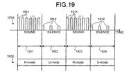
- FIG. 19 is a diagram of an example of changing the ROHC operation mode.
- the horizontal axis represents time.
- Reference numeral 1910 represents audio data transmitted from the transmission node 200 to the reception node 100.
- AMR data 1911 is transmitted when audio (sound) is to be transmitted.
- SID data 1912 is transmitted when there is no audio to be transmitted (silence).
- Intervals 1921-1924 are temporally continuous intervals of time.
- the voice-communication state in the intervals 1921 and 1923 is "sound" and AMR data 1911 is transmitted.
- the voice-communication state in the intervals 1922 and 1924 is "silence" and SID data 1912 is transmitted.
- Reference numeral 1930 indicates the ROHC operations modes switched to by the reception node 100.
- the reception node 100 determines that the voice-communication state is "sound" in the intervals 1921 and 1923 and the reception node 100 changes the ROHC operation mode to the R-mode (or the O-mode, for example) in intervals 1921 and 1923.
- the reception node 100 determines that the voice-communication state is "silence" in the intervals 1922 and 1924 and the reception node 100 changes the ROHC operation mode to the U-mode in the intervals 1922 and 1924.
- the ROHC operation mode is set to the U-mode, which has high header compression frequency.
- the wireless band utilization efficiency can be improved.
- the ROHC operation mode is set to the R-mode, which has low header compression frequency. As a result, sound quality can be improved.
- the voice-communication state is determined and according to the determined voice-communication state, the ROHC operation mode can be changed. Consequently, when the voice-communication state is "sound”, sound quality can be improved and when the voice-communication state is "silence”, efficient header compression can be facilitated. Therefore, the quality of audio data and band utilization efficiency can be improved.
- the volume of accumulated data in the reception buffer 131 is measured and based on the measured volume of accumulated data, the voice-communication state can be determined. For example, by comparing the measured volume of accumulated data and a threshold, the voice-communication state ("sound" or "silence”) can be easily determined.
- the transmission node 200 uses the BSR that is transmitted to the reception node 100 to determine the voice-communication state.
- BSR (see FIGS. 11- 13 ), which indicates the volume of data accumulated in the transmission buffer 211 of the transmission node 200, is included in the MAC_Control_Element of the MAC_PDU (see FIG. 10 ) that the transmission node 200 transmits to the reception node 100.
- FIG. 20 is a block diagram of an example of configuration of the reception node according to the second embodiment.
- the MAC layer terminal unit 110 of the reception node 100 according to the second embodiment includes a reception processing unit 2011, an MCE terminal unit 2012, and a transmission processing unit 2013.
- the reception processing unit 2011 performs reception processing in the MAC layer.
- the reception processing unit 2011 outputs reception processed data to the RLC layer terminal unit 120 and the MCE terminal unit 2012.
- the MCE terminal unit 2012 is a terminus of the MCE (MAC_Control_Element). For example, the MCE terminal unit 2012 acquires the BSR (see FIGS. 11-13 ) included in data output from the reception processing unit 2011.
- the BSR indicates the volume of accumulated data in the transmission buffer 211 of the transmission node 200.
- the MCE terminal unit 2012 outputs the acquired BSR, as the accumulated data volume, to the PDCP terminal unit 130.
- the transmission processing unit 2013 performs transmission processing in the MAC layer.
- the transmission processing unit 2013 transmits transmission processed data to the transmission node 200.
- the voice-communication state determining unit 134 of the PDCP terminal unit 130 determines the voice-communication state, based on the accumulated data volume indicated by the BSR output from the MCE terminal unit 2012. For example, if the accumulated data volume output is greater than a threshold, the voice-communication state determining unit 134 determines that the voice-communication state is "sound”. If the accumulated data volume is less than or equal to the threshold, the voice-communication state determining unit 134 determines that the voice-communication state is "silence".
- FIG. 21 is a flowchart of an example of operation of the transmission node according to the second embodiment. Fundamental operations of the reception node 100 depicted in FIG. 20 are identical to those depicted in FIG. 17 . Furthermore, the voice-communication state determining unit 134 of the reception node 100 depicted in FIG. 20 performs the following steps at step S1701 depicted in FIG. 17 .
- the voice-communication state determining unit 134 determines whether the time that has elapsed since the start of the operation has become at least equal to a monitoring cycle (step S2101), and waits until the elapsed time is equal to or greater than the monitoring cycle (step S2101: NO). When the elapsed time has become equal to or greater than the monitoring cycle (step S2101: YES), the voice-communication state determining unit 134 receives, through the MCE terminal unit 2012, the data-volume information (BSR) transmitted from the transmission node 200 (step S2102). The data-volume information received at step S2102 indicates the volume of accumulated data in the transmission buffer 211 of the transmission node 200.
- BSR data-volume information
- the voice-communication state determining unit 134 determines whether the voice-communication state stored in memory at the previous determination of the voice-communication state, is "sound" (step S2103). If the voice-communication state is "sound" (step S2103: YES), the voice-communication state determining unit 134 determines whether the accumulated data volume indicated by the data-volume information received at step S2102 is at most a threshold (step S2104). If the accumulated data volume is not equal to or less than the threshold (step S2104: NO), the series of operations ends.
- step S2104 If the accumulated data volume indicated by the data-volume information received is less than or equal to the threshold, at step S2104 (step S2104: YES), the voice-communication state determining unit 134 updates the voice-communication state stored in the memory, to "silence" (step S2105), ending the series of operations.
- step S2103 if the voice-communication state is not "sound" (step S2103: NO), the voice-communication state determining unit 134 determines whether the accumulated data volume indicated by the data-volume information received at step S2102, is greater than the threshold (step S2106). If the accumulated data volume is not greater than the threshold (step S2106: NO), the series of operations ends.
- step S2106 if the accumulated data volume indicated by the received data-volume information is greater than the threshold (step S2106: YES), the voice-communication state determining unit 134 updates the voice-communication state stored in the memory to "sound" (step S2107), ending the series of operations.
- the threshold used for comparison also uses the index depicted in FIG. 14 .
- the voice-communication state is determined and according to the determined voice-communication state, the ROHC operation mode can be changed. Consequently, when the voice-communication state is "sound”, sound quality can be improved and when the voice-communication state is "silence”, efficient header compression can be facilitated. As a result, the sound quality of audio data and band utilization efficiency can be improved.
- the volume of accumulated data in the transmission buffer 211 is measured and data-volume information indicating the measured volume of accumulated data is transmitted to the reception node 100. Consequently, the reception node 100 can determine the voice-communication state, based on the data-volume information received from the transmission node 200.
- Use of the accumulated data volume on the transmission node 200 side enables accurate determination of the voice-communication state, irrespective of the wireless interval quality, etc.
- the transmission node 200 uses the BSR included in the MAC_Control_Element of the MAC_PDU (see FIG. 10 ) transmitted to the reception node 100 and transmits data-volume information, whereby the data-volume information can be transmitted to the reception node 100 without newly adding a control signal that is to be transmitted from the transmission node 200 to the reception node 100.
- FIG. 22 is a block diagram of an example of configuration of the reception node according to a third embodiment.
- parts identical to those depicted in FIG. 1 are given the same reference numerals used in FIG. 1 and description thereof is omitted.
- the voice-communication state determining unit 134 depicted in FIG. 1 may be omitted.
- the reception processing unit 132 outputs to the ROHC control unit 135, voice-communication state information that is transmitted from the transmission node 200. According to the voice-communication state determination results ("sound" or "silence") indicated by the voice-communication state information output from the reception processing unit 132, the ROHC control unit 135 changes the ROHC operation mode.
- FIG. 23 is a block diagram of an example of configuration of the transmission node according to the third embodiment.
- the PDCP terminal unit 210 of the transmission node 200 according to the third embodiment includes a voice-communication state determining unit 2310 in addition to the configuration depicted in FIG. 2 .
- the voice-communication state determining unit 2310 determines the voice-communication state of audio data transmitted from the transmission node 200 to the reception node 100 and outputs to the transmission processing unit 213, voice-communication state information indicating the determination results.
- the voice-communication state determined by the voice-communication state determining unit 2310 is, for example, a state related to whether the audio of the audio data is "sound" or "silence".
- the voice-communication state determining unit 2310 determines the voice-communication state, based on the volume of accumulated data in the transmission buffer 211.
- the voice-communication state determining unit 2310 determines that the voice-communication state is "sound" and if the volume of accumulated data in the transmission buffer 211 less than or equal to the threshold, the voice-communication state determining unit 2310 determines that the voice-communication state is "silence".
- the threshold compared with the volume of accumulated data is, for example, the voice-communication state "silence" and a value that corresponds to the volume of SID data accumulated in the transmission buffer 211 when the transmission node 200 transmits SID data.
- the transmission processing unit 213 outputs, through the RLC layer terminal unit 220 and the MAC layer terminal unit 230, to the reception node 100, the voice-communication state information output from the voice-communication state determining unit 2310, enabling the voice-communication state information to be transmitted to the reception node 10.
- a PDCP frame for transmitting the voice-communication state information is described with reference to FIG. 24 .
- FIG. 24 is a diagram of an example of PDCP frame format.
- the PDCP header frame format of the control PDU that the transmission processing unit 213 transmits to the reception node 100 for example, is that of a PDCP frame 2400 depicted in FIG. 24 .
- the PDCP frame 2400 includes the D/C 1510, the PDU type 1610, the R 1520, and a telephone call status flag (TSF) 2410.
- the D/C 1510 is "0" indicating a control PDU.
- the TSF 2410 indicates the voice-communication state of audio data transmitted from the transmission node 200 to the reception node 100.
- the transmission processing unit 213 stores to the TSF 2410 of the PDCP frame 2400, the voice-communication state information output from the voice-communication state determining unit 2310.
- the reception processing unit 132 of the reception node 100 outputs to the ROHC control unit 135 and as the voice-communication state information, the TSF 2410 of the PDCP frame 2400 received from the transmission node 200.
- FIG. 25 is a flowchart of an example of operation of the transmission node depicted in FIG. 23 .
- the transmission node 200 depicted in FIG. 23 performs the steps depicted in FIG. 25 .
- the voice-communication state determining unit 2310 of the transmission node 200 determines the voice-communication state of audio data transmitted from the transmission node 200 to the reception node 100 (step S2501).
- the voice-communication state determining unit 2310 determines whether the voice-communication state determined at step S2501 has changed from the voice-communication state that was previously determined by the voice-communication state determining unit 2310 (step S2502). If the voice-communication state has not changed (step S2502: NO), the transmission node 200 returns to step S2501 and continues processing therefrom.
- step S2502 if voice-communication state has changed (step S2502: YES), the transmission processing unit 213 transmits to the reception node 100, voice-communication state information that indicates the voice-communication state determined at step S2501 (step S2503), ending the series of operations.
- the voice-communication state information transmitted at step S2503 is received by the reception node 100.
- the reception node 100 changes the ROHC operation mode for communication with the transmission node 200.
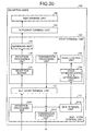
- FIG. 26 is a flowchart of step S2501 depicted in FIG. 25 .
- the voice-communication state determining unit 2310 executes the following steps.
- the voice-communication state determining unit 2310 determines whether the time that has elapsed since the start of operation has become at least equal to a monitoring cycle (step S2601), and waits until the elapsed time is equal to or greater than the monitoring cycle (step S2601: NO).
- step S2601 when the elapsed time has become equal to or greater than the monitoring cycle (step S2601: YES), the voice-communication state determining unit 2310 measures the volume of accumulated data in the transmission buffer 211 (step S2602).
- Steps S2603-S2607 depicted in FIG. 26 are identical to steps S1803-S1807 depicted in FIG. 18 and description thereof is omitted.
- the voice-communication state is determined and according to the determined voice-communication state, the ROHC operation mode can be changed. Consequently, when the voice-communication state is "sound”, sound quality can be improved and when the voice-communication state is "silence”, efficient header compression can be facilitated. As a result, the sound quality of audio data and band utilization efficiency can be improved.
- the voice-communication state is determined and voice-communication state information indicating the determination results is transmitted to the reception node 100, whereby the reception node 100 can change the ROHC operation mode according to the voice-communication state indicated by the voice-communication state information received from the transmission node 200.
- the voice-communication state can be accurately determined, irrespective of wireless interval quality.
- the transmission node 200 includes the TSF 2410 in the PDCP frame 2400 that is transmitted to the reception node 100, uses the TSF 2410, and transmits voice-communication state information, whereby the voice-communication state information can be transmitted to the reception node 100.
- FIG. 27 is a block diagram of an example of configuration of the reception node according to a fourth embodiment.
- the reception processing unit 132 of the reception node 100 according to the fourth embodiment outputs to the voice-communication state determining unit 134, data-volume information that is among the reception processed data.
- the data-volume information that is output to the voice-communication state determining unit 134 indicates the volume of accumulated data in the transmission buffer 211 in the transmission node 200.
- the voice-communication state determining unit 134 determines the voice-communication state, based on the data-volume information output from the reception processing unit 132. For example, if the accumulated data volume is greater than a threshold, the voice-communication state determining unit 134 determines that the voice-communication state is "sound" and if the accumulated data volume is less than or equal to the threshold, the voice-communication state determining unit 134 determines that voice-communication state is "silence".
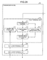
- FIG. 28 is a block diagram of an example of configuration of the transmission node according to the fourth embodiment.
- the PDCP terminal unit 210 of the transmission node 200 according to the third embodiment includes a data-volume measuring unit 2810 in addition to the configuration depicted in FIG. 2 .
- the data-volume measuring unit 2810 measures the volume of accumulated data in the transmission buffer 211 and outputs to the transmission processing unit 213, data-volume information that indicates the measured volume of accumulated data.
- the transmission processing unit 213 transmits to the reception node 100, through the RLC layer terminal unit 220 and the MAC layer terminal unit 230, the data-volume information output from the data-volume measuring unit 2810. Consequently, the data-volume information can be transmitted to the reception node 100.
- the PDCP frame for transmitting the data-volume information will be described with reference to FIG. 29 .
- FIG. 29 is a diagram of an example of PDCP frame format.
- the PDCP header frame format of the control PDU that is transmitted by the transmission processing unit 213 of the transmission node 200 is, for example, that of a PDCP frame 2900 depicted in FIG. 29 .
- the PDCP frame 2900 includes the D/C 1510, the PDU type 1610, and a BSR 2910.
- the D/C 1510 is "0" indicating a control PDU.
- the BSR 2910 indicates the volume of accumulated data in the transmission buffer 211 of the transmission node 200.
- the transmission processing unit 213 stores to the BSR 2910 of the PDCP frame 2900, the data-volume information output from the data-volume measuring unit 2810 and further transmits the data-volume information to the reception node 100.
- the reception processing unit 132 of the reception node 100 outputs to the voice-communication state determining unit 134, as the accumulated data volume, the BSR 2910 of the PDCP frame 2900 received from the transmission node 200.
- the voice-communication state is determined and according to the determined voice-communication state, the ROHC operation mode can be changed. Consequently, when the voice-communication state is "sound”, the sound quality can be improved and when the voice-communication state is "silence", efficient header compression can be facilitated.
- the volume of accumulated data in the transmission buffer 211 is measured and data-volume information that indicates the measured volume of accumulated data is transmitted to the reception node 100, whereby based on the accumulated data volume indicated by the data-volume information received from the transmission node 200, the reception node 100 can determine the voice-communication state.
- Use of the accumulated data volume on the transmission node 200 side enables the voice-communication state to be accurately determined, irrespective of wireless interval quality.
- the transmission node 200 includes the BSR 2910 in the PDCP frame 2900 transmitted to the reception node 100, uses the BSR 2910, and transmits the data-volume information, whereby the accumulated data volume can be reported to the reception node 100 by the transmission node 200.
- the voice-communication state determining unit 134 of the reception node 100 determines that the voice-communication state is "sound", if the volume of accumulated data in the reception buffer 131 is greater than a threshold for a given period or longer. If the volume of accumulated data in the reception buffer 131 is less than or equal to the threshold for the given period or longer, the voice-communication state determining unit 134 determines that the voice-communication state is "silence".
- the configurations of the reception node 100 and the transmission node 200 are, for example, identical to the configurations depicted in FIG. 1 and FIG. 2 .
- FIG. 30 is a flowchart of an example of operation of the reception node according to the fifth embodiment. Fundamental operations of the reception node 100 according to the fifth embodiment are identical to those depicted in FIG. 17 . Furthermore, the voice-communication state determining unit 134 of the reception node 100 according to the fifth embodiment performs the following steps at step S1701 depicted in FIG. 17 .
- the voice-communication state determining unit 134 sets a counter k to 0 (step S3001), determines whether the time that has elapsed since the start of operation is at least equal to a monitoring cycle (step S3002), and waits until the elapsed time is equal to or greater than the monitoring cycle (step S3002: NO).
- step S3002 when the elapsed time becomes equal to or greater than the monitoring cycle (step S3002: YES), the voice-communication state determining unit 134 measures the volume of accumulated data in the reception buffer 131 (step S3003) and determines whether the voice-communication state stored in memory at the previous determination of the voice-communication state, is "sound" (step S3004).
- step S3004 if the voice-communication state is "sound" (step S3004: YES), the voice-communication state determining unit 134 determines whether the volume of accumulated data measured at step S3003 is at most a threshold (step S3005). If the volume of accumulated data is not less than or equal to the threshold (step S3005: NO), the voice-communication state determining unit 134 proceeds to step S3009 and continues processing therefrom.
- step S3007 if the counter k is not greater than the protective-step count (step S3007: NO), the voice-communication state determining unit 134 returns to step S3002 and continues processing therefrom. If the counter k is greater than the protective-step count (step S3007: YES), the voice-communication state determining unit 134 updates the voice-communication state stored in the memory, to "silence" (step S3008) and sets the counter k to 0 (step S3009), ending the series of operations.
- step S3004 if the voice-communication state is not "sound" (step S3004: NO), the voice-communication state determining unit 134 determines whether the accumulated data volume measured at step S3003 is greater than the threshold (step S3010). If the accumulated data volume is not greater than the threshold (step S3010: NO), the voice-communication state determining unit 134 proceeds to step S3014 and continues processing therefrom.
- step S3012 if the counter k is not greater than the protective-step count (step S3012: NO), the voice-communication state determining unit 134 returns to step S3002 and continues processing therefrom. If the counter k is greater than the protective-step count (step S3012: YES), the voice-communication state determining unit 134 updates the voice-communication state stored in the memory, to "sound" (step S3013) and sets the counter k to 0 (step S3014), ending the series of operations.
- the voice-communication state determining unit 134 disregards cases when the value of the counter k is less than the protective-step count, even if the volume of accumulated data is less than or equal to the threshold at step S3005. As a result, if the volume of accumulated data in the reception buffer 131 is less than or equal to the threshold for a given period or longer, the voice-communication state determining unit 134 is able to determine that the voice-communication state is "silence".
- the voice-communication state determining unit 134 disregards cases when the value of the counter k is less than the protective-step count, even if the accumulated data volume is greater than the threshold at step S3010. As a result, if the volume of accumulated data in the reception buffer 131 is greater than the threshold for the given period or longer, the voice-communication state determining unit 134 is able to determine that the voice-communication state is "sound".
- FIG. 31 is a diagram of an example of voice-communication state determination by the operations depicted in FIG. 30 .
- parts identical to those depicted in FIG. 19 are given the same reference numerals used in FIG. 19 and description thereof is omitted.
- the horizontal axis represents time.
- Reference numeral 3110 represents audio data transmitted from the transmission node 200 to the reception node 100.
- the initial voice-communication state is assumed to be "silence"
- the monitoring cycle is assumed to be 20[ms]
- the threshold (corresponds to size of SID data 1912) is assumed to be 10[bytes]
- the protective-step count is assumed to be 3.
- the reception node 100 acquires the volume of accumulated data in the reception buffer 131 during the monitoring cycle 20[ms] and if the accumulated data volume exceeds the threshold of 10[bytes], the reception node 100 increments the counter k.
- Monitoring cycles T1-T23 are the monitoring cycles (20[ms]) in the reception node 100.
- the reception node 100 determines that the voice-communication state is still "silence”. As a result, in the monitoring cycles T1-T3, the voice-communication state is determined to be "silence".
- the reception node 100 determines that the voice-communication state has changed to "sound”.
- the actual voice-communication state of the audio data transmitted from the transmission node 200 to the reception node 100 is "silence". It is assumed that in each of the monitoring cycles T12, T16, T20, the reception node 100 properly receives the SID data 1912 (size of 10[bytes]).
- the voice-communication state determining unit 134 disregards cases where the value of the counter k does not exceed the protective-step count. As a result, if the reception node 100 cannot properly receive the AMR data 1911, errant determination that the voice-communication state has changed to "silence" can be prevented.
- the voice-communication state is determined and according to the determined voice-communication state, the ROHC operation mode can be changed. Consequently, when the voice-communication state is "sound”, sound quality can be improved and when the voice-communication state is "silence”, efficient head compression can be facilitated. As a result, the sound quality of audio data and band utilization efficiency can be improved.
- the voice-communication state is determined to be "sound", whereby errant determination that the voice-communication state has changed to "sound" due to instantaneous traffic increases, can be prevented.
- the voice-communication state is determined to be "silence", whereby errant determination that the voice-communication state has changed to "sound" due to instantaneous traffic decreases caused by missing frames, can be prevented.
- the configurations of the reception node 100 and the transmission node 200 have been described to be the configurations depicted in FIG. 1 and FIG. 2 (first embodiment). However, the configurations of the reception node 100 and the transmission node 200 may be identical to those of any one of the second to fourth embodiments. As one example, a case in which the configurations of the reception node 100 and the transmission node 200 are identical to the configurations depicted in FIG. 22 and FIG. 23 (third embodiment) will be described.
- the voice-communication state determining unit 2310 of the transmission node 200 determines that the voice-communication state is "sound”. Further, if the data accumulated in the transmission buffer 211 is less than or equal to the threshold for the given period or longer, the voice-communication state determining unit 2310 determines that the voice-communication state is "silence”.
- a configuration in which the ROHC control unit 135 is disposed in the reception node 100 and ROHC switching control is performed by the reception node 100 has been described.
- a function corresponding to the ROHC control unit 135 is provided to the transmission node 200 and the ROHC switching control is performed by the transmission node 200.
- FIG. 32 is a block diagram of an example of configuration of the reception node according to the sixth embodiment.
- parts identical to those depicted in FIG. 22 are given the same reference numerals used in FIG. 22 and description thereof is omitted.
- the ROHC control unit 135 and the transmission processing unit 136 depicted in FIG. 22 may be omitted.
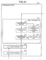
- FIG. 33 is a block diagram of an example of configuration of the transmission node according to the sixth embodiment.
- the PDCP terminal unit 210 of the transmission node 200 according to the sixth embodiment includes an ROHC control unit 3310 in addition to the configuration depicted in FIG. 23 .
- the reception processing unit 214 depicted in FIG. 23 may be omitted.
- the voice-communication state determining unit 2310 outputs to the ROHC control unit 3310, voice-communication state information that indicates voice-communication state determination results.
- the ROHC control unit 3310 (control unit) changes the ROHC operation mode for the reception node 100 and the transmission node 200, according to the determination results output from the voice-communication state determining unit 2310. To change the ROHC operation mode, the ROHC control unit 3310 notifies the compressing unit 212 of the operation mode to be changed to.
- the ROHC control unit 3310 generates a change instructing signal that indicates the operation mode to be changed to.
- the ROHC control unit 3310 outputs the generated change-instructing signal to the transmission processing unit 213, whereby the change instructing signal is transmitted to the reception node 100 and the ROHC operation mode is changed.
- Changing of the ROHC operation mode by the ROHC control unit 3310 is identical to that by the ROHC control unit 135 described above and description thereof is omitted.
- the compressing unit 212 depicted in FIG. 33 writes header compressed audio data to memory (not depicted) of the transmission node 200.
- the compressing unit 212 for example, is a computing unit such as a CPU.
- the transmission processing unit 213 reads out the audio data stored to the memory of the transmission node 200 by the compressing unit 212 and transmits the audio data.
- the voice-communication state determining unit 2310 writes the voice-communication state determination results to the memory (not depicted) of the transmission node 200.
- the voice-communication state determining unit 2310 is, for example, a computing unit such as a CPU.
- the ROHC control unit 3310 reads out the determination results stored to the memory of the transmission node 200 by the voice-communication state determining unit 2310 and according to the determination results, changes the ROHC operation mode.
- the ROHC control unit 3310 is, for example, a computing unit such as a CPU.
- the voice-communication state is determined and according to the determined voice-communication state, the ROHC operation state can be changed. Consequently, when the voice-communication state is "sound”, sound quality can be improved and when the voice-communication state is "silence”, efficient header compression can be facilitated. As a result, the sound quality of audio data and band utilization efficiency can be improved.
- the voice-communication state is determined and based on the results, the ROHC operation mode can be changed, whereby the voice-communication state can be accurately determined, irrespective of the wireless interval quality. Further, since the voice-communication state determination and the changing of the ROHC operation mode is performed on the transmission node 200 side, the processing load on the reception node 100 side can be reduced.
- FIG. 34 is a diagram of an example of switching from the U-mode to the O-mode.
- C_MODE 3410 indicates the ROHC operation mode set in the compressing unit 212 of the transmission node 200.
- the C_MODE 3410 indicates any one among “U-mode”, “O-mode”, and "R-mode”.
- C_TRANS 3420 indicates the transition state of the ROHC operation mode in the compressing unit 212 of the transmission node 200.
- the C_TRANS 3420 indicates any one among "Pending” and "Done”.
- D_MODE 3430 indicates the ROHC operation mode set in the expanding unit 133 of the reception node 100.
- the D_MODE 3430 indicates any one of "U-mode”, “O-mode”, and "R-mode”.
- D_TRANS 3440 indicates the transition state of the ROHC operation mode set in the expanding unit 133 of the reception node 100.
- the D_TRANS 3440 indicates any one among "Initiated”, “Pending”, and "Done”.
- Switching from the U-mode to the O-mode can be performed at an arbitrary timing, if a feedback channel is available from the reception node 100 to the transmission node 200. For example, during the interval before period t3411, it is assumed that the ROHC operation mode of the reception node 100 and the transmission node 200 is the U-mode.
- the reception node 100 transmits to the transmission node 200, a change instructing signal 3450 that indicates that the ROHC operation mode is to be changed to the O-mode.
- the transmission node 200 upon receiving the change instructing signal 3450 from the reception node 100, changes the ROHC operation mode in the transmission node 200 to the O-mode.
- the transmission node 200 suspends the cyclic transmission of the uncompressed frames 511 and transmits the compressed frame 512 until a Nack is received from the reception node 100.
- the switch can be performed at an arbitrary timing in the reception node 100 and the transmission node 200, the switch can be performed with the C_TRANS 3420 and the D_TRANS 3440 as is, indicating "Done".
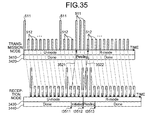
- FIG. 35 is a diagram of an example of switching from the U-mode to the R-mode.
- parts identical to those depicted in FIG. 34 are given the same reference numerals used in FIG. 34 and description thereof is omitted.
- the switch from the U-mode to the R-mode is performed after at least 1 uncompressed frame 511 has been received properly. For example, during the interval before period t3511, the ROHC operation mode of the reception node 100 and the transmission node 200 is assumed to be the U-mode.
- the reception node 100 transmits to the transmission node 200, a change instructing signal 3521 that indicates that the ROHC operation mode is to be changed to the R-mode.
- the transmission node 200 upon receiving the change instructing signal 3521 from the reception node 100, changes the operation mode to the R-mode and continues to transmit the uncompressed frame 511 to the reception node 100.
- the reception node 100 upon receiving the uncompressed frame 511 transmitted from the transmission node 200, changes the ROHC operation mode in the reception node 100 to the R-mode. During the interval from the period t3511 when the reception node 100 transmits the change instructing signal 3521 until the period t3512 when the reception node 100 receives the uncompressed frame 511 transmitted from the transmission node 200, the D_TRANS 3440 indicates "Initiated".
- the reception node 100 if the reception node 100 properly receives the uncompressed frame 511 transmitted from the transmission node 200, the reception node 100 transmits an Ack 3522 to the transmission node 200. Upon receiving the ACK 3522, the transmission node 200 continues to transmit the compressed frame 512 to the reception node 100, until a Nack is received from the reception node 100.
- the C_TRANS 3420 indicates “Pending”. Further, the D_TRANS 3440 indicates "Pending” during the interval from the period t3512 when the reception node 100 transmits the Ack 3522 until the period t3513 when the reception node 100 receives the compressed frame 512.
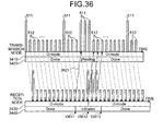
- FIG. 36 is a diagram of an example of switching from the O-mode to the U-mode.
- parts identical to those depicted in FIG. 34 are given the same reference numerals used in FIG. 34 and description thereof is omitted.
- the switch from the O-mode to the U-mode can be performed at an arbitrary timing. For example, during an interval before period t3611, the ROHC operation mode of the reception node 100 and the transmission node 200 is assumed to be the O-mode.
- the reception node 100 transmits to the transmission node 200, a change instructing signal 3621 that indicates that the ROHC operation mode is to be changed to the U-mode.
- the transmission node 200 upon receiving the change instructing signal 3621 from the reception node 100, changes the ROHC operation mode in the transmission node 200 to the U-mode.
- the transmission node 200 starts the cyclic transmission of the uncompressed frame 511.
- configuration may be such that when the transmission node 200 changes the ROHC operation mode to the U-mode, the transmission node 200 transmits the uncompressed frame 511 3 times consecutively and receives from the reception node 100, Acks in response to the uncompressed frames 511. Consequently, it can be confirmed that the operation mode switch was performed properly (Three-way handshake).
- the reception node 100 changes the ROHC operation mode to the U-mode.
- the D_TRANS 3440 indicates "Initiated" during the interval from the period t3611 when the reception node 100 transmits the change instructing signal 3621 until the period t3613 when the reception node 100 receives the compressed frame 512 from the transmission node 200.
- the switch from the R-mode to the U-mode is identical to the switch from the O-mode to the U-mode and description thereof is omitted.
- the voice-communication state is determined and according to the determined voice-communication state, the ROHC operation mode can be changed. Consequently, when the voice-communication state is "sound”, the sound quality can be improved and when the voice-communication state is "silence", efficient header compression can be facilitated. Therefore, the sound quality of audio data and band utilization efficiency can be improved.
- the disclosed receiving apparatus, transmitting apparatus, receiving method, transmitting method, communications system, and communication method are further applicable to other communications system, such as WiMAX.
- configuration in which the ROHC operation mode is changed to the O-mode or the R-mode when the voice-communication state is "sound” and the ROHC operation mode is changed to the U-mode when the voice-communication state is "silence".
- configuration may be such that when the voice-communication state is "sound”, the ROHC operation mode is changed to the R-mode and when the voice-communication state is "silence", the ROHC operation mode is changed to the O-mode.
- header compression efficiency can be improved.
- various types of operation modes having different header compression frequencies can be used.
Landscapes
- Engineering & Computer Science (AREA)
- Computer Networks & Wireless Communication (AREA)
- Signal Processing (AREA)
- Computer Security & Cryptography (AREA)
- Mobile Radio Communication Systems (AREA)
- Telephone Function (AREA)
- Telephonic Communication Services (AREA)
Abstract
Description
- The present invention relates to a receiving apparatus, a transmitting apparatus, a receiving method, a transmitting method, a communications system, and a communication method that perform audio communication.
- Long Term Evolution (LTE) systems aim to improve performance by leaps and bounds from 3G cellular systems and under the 3rd Generation Partnership Project (3GPP), advances are being made toward international standardization. LTE systems realize high speed transmission in mobile communication, provide high speed service environments such as high speed image delivery, and are expected to facilitate efficient frequency utilization.
- Further, although in existing systems (3G), audio and data communication have been provided by separate communication infrastructures, in LTE systems, movement towards "all IP" integrating audio and data communication to an IP base is intended, whereby completely IP-based systems are expected to be realized by LTE systems, from systems that include conventional circuit switching infrastructure.
- Real-time data transmission in LTE systems, similar to Voice over IP (VoIP) in typical wired IP networks, is implemented by RTP/UDP/IP protocols. Consequently, real-time data in LTE systems have large overhead due to the headers appended for each protocol.
- In networks that include wireless intervals of limited bandwidth, to improve the bandwidth utilization efficiency of the wireless intervals, a function to compress the protocol headers, which cause overhead, is demanded. This header compression function is expected to be realized in LTE systems.
- For example, a technique called Robust Header Compressing (ROHC) included in a Packet Data Convergence Protocol (PDCP) between eNB and UE is expected to implement header compression. Multiple operation modes, each having a different header compression efficiency exist in ROHC (see, for example,
Patent Document 1 below). -
- Patent Document 1: Japanese Laid-Open Patent Publication No.
2002-135362 - Nevertheless, with the above conventional technology, a problem arises in that the quality of audio data degrades, if header compression is performed frequently and frames are missing. On the other hand, if the frequency of header compression is set to be low, a problem arises in that the data overhead becomes large, whereby the band utilization efficiency of the transmission path decreases.
- In addition to solving the problems above, an object of the disclosed receiving apparatus, transmitting apparatus, receiving method, transmitting method, communications system and communication method is to improve the sound quality of audio data and improve band utilization efficiency.
- To solve the problems above and achieve an object, the receiving apparatus is a receiving apparatus in a communications system that performs header compression of audio data and has multiple operation modes that each have a different compression frequency. The receiving apparatus includes a receiving unit that receives the audio data transmitted by a transmitting apparatus, which performs the header compression; a determining unit that determines the voice-communication state of the audio data received by the receiving unit; and a control unit that changes the operation mode, according to a determination result obtained by the determining unit.
- According to the configuration above, the voice-communication state is determined and according to the voice-communication state, multiple operation modes, each having a different header compression frequency, can be switched between.
- According to the disclosed receiving apparatus, transmitting apparatus, receiving method, transmitting method, communications system, and communication method, the sound quality of audio data and band utilization efficiency can be improved.
-
-
FIG. 1 is a block diagram of an example of configuration of a reception node according to a first embodiment; -
FIG. 2 is a block diagram of an example of configuration of a transmission node according to the first embodiment; -
FIG. 3 is a diagram of an example of configuration of a communications system according to the first embodiment; -
FIG. 4 is a diagram of a protocol stack in the communications system depicted inFIG. 3 ; -
FIG. 5 is a diagram of U-mode operation of ROHC (part 1); -
FIG. 6 is a diagram of the U-mode operation of ROHC (part 2); -
FIG. 7 is a diagram of O-mode operation of ROHC; -
FIG. 8 is a diagram of R-mode operation of ROHC; -
FIG. 9 is a diagram of an example of a change in the voice-communication state; -
FIG. 10 is a diagram of an example of MAC_PDU; -
FIG. 11 is a diagram of MAC_Control_Elements depicted inFIG. 10 ; -
FIG. 12 is a diagram of a Short_BSR depicted inFIG. 11 ; -
FIG. 13 is a diagram of a Long_BSR depicted inFIG. 11 ; -
FIG. 14 is a diagram of a buffer size index; -
FIG. 15 is a diagram of a data PDU format; -
FIG. 16 is a diagram of an example of control PDU format; -
FIG. 17 is a flowchart of an example of operation of the reception node depicted inFIG. 1 ; -
FIG. 18 is a flowchart of step S1701 depicted inFIG. 17 ; -
FIG. 19 is a diagram of an example of changing the ROHC operation mode; -
FIG. 20 is a block diagram of an example of configuration of the reception node according to a second embodiment; -
FIG. 21 is a flowchart of an example of operation of the transmission node according to the second embodiment; -
FIG. 22 is a block diagram of an example of configuration of the reception node according to a third embodiment; -
FIG. 23 is a block diagram of an example of configuration of the transmission node according to the third embodiment; -
FIG. 24 is a diagram of an example of PDCP frame format; -
FIG. 25 is a flowchart of an example of operation of the transmission node depicted inFIG. 23 ; -
FIG. 26 is a flowchart of step S2501 depicted inFIG. 25 ; -
FIG. 27 is a block diagram of an example of configuration of the reception node according to a fourth embodiment; -
FIG. 28 is a block diagram of an example of configuration of the transmission node according to the fourth embodiment; -
FIG. 29 is a diagram of an example of PDCP frame format; -
FIG. 30 is a flowchart of an example of operation of the reception node according to a fifth embodiment; -
FIG. 31 is a diagram of an example of voice-communication state determination by the operations depicted inFIG. 30 ; -
FIG. 32 is a block diagram of an example of configuration of the reception node according to a sixth embodiment; -
FIG. 33 is a block diagram of an example of configuration of the transmission node according to the sixth embodiment; -
FIG. 34 is a diagram of an example of switching from the U-mode to the O-mode; -
FIG. 35 is a diagram of an example of switching from the U-mode to the R-mode; and -
FIG. 36 is a diagram of an example of switching from the O-mode to the U-mode. -
- 300 communications system
- 311, 312 MME/S-GW
- 321-323 eNB
- 331, 332 UE
- 400 protocol stack
- 511 uncompressed frame
- 512 compressed frame
- 801, 3522 Ack
- 911, 1911 AMR data
- 912, 1912 SID data
- 1000 MAC_PDU
- 1500, 1600, 2400, 2900 PDCP frame
- 3410 C_MODE
- 3420 C_TRANS
- 3430 D_MODE
- 3440 D_TRANS
- 3450, 3521, 3621 change instructing signal
- T1-T23 monitoring cycle
- With reference to the accompanying drawings, preferred embodiments of the receiving apparatus, the transmitting apparatus, the receiving method, the transmitting method, the communications system, and the communication method are described in detail.
-
FIG. 1 is a block diagram of an example of configuration of a reception node according to a first embodiment. Areception node 100 depicted inFIG. 1 is an example of application of the receiving apparatus according to the embodiment, to user equipment (UE) such as a user terminal in an LTE system. Thereception node 100 includes a MAClayer terminal unit 110, an RLClayer terminal unit 120, aPDCP terminal unit 130, an RTP/UDP/IP terminal unit 140, and anAMR terminal unit 150. - The MAC
layer terminal unit 110 is a terminus of a MAC layer in the communication with the transmission node (seeFIG. 2 ). For example, the MAClayer terminal unit 110 corrects errors and controls retransmission of audio data or control data transmitted from the transmission node. The RLClayer terminal unit 120 is a terminus of an RLC layer in the communication with the transmission node. - The
PDCP terminal unit 130 is a terminus of a PDCP layer in the communication with the transmission node. Further, thePDCP terminal unit 130 is a terminus of the ROHC layer in the communication with the transmission node. For example, thePDCP terminal unit 130 includes areception buffer 131, areception processing unit 132, an expandingunit 133, a voice-communicationstate determining unit 134, anROHC control unit 135, and atransmission processing unit 136. - The
reception buffer 131 temporarily stores PDCP_PDU received through the MAClayer terminal unit 110 and the RLClayer terminal unit 120. The reception processing unit 132 (receiving unit) reads out the PDCP_PDU stored in thereception buffer 131, performs header processing on the PDCP_PDU, and outputs the PDCP_PDU to the expandingunit 133. The PDCP_PDU readout by thereception processing unit 132 is erased from thereception buffer 131. - The expanding
unit 133 expands the ROHC header of the data output from thereception processing unit 132 and outputs the data to the RTP/UDP/IP terminal unit 140. The expandingunit 133 expands the ROHC header according to the operation mode, which is changed by theROHC control unit 135. - The voice-communication state determining unit 134 (determining unit) determines the voice-communication state of the audio data received by the
reception node 100 from the transmission node and notifies theROHC control unit 135 of the determination results. A voice-communication state is, for example, a state related to whether the audio of the audio data is "sound" or "silence". The voice-communicationstate determining unit 134, for example, determines the voice-communication state, based on the volume of accumulated data in thereception buffer 131. - For example, if the volume of accumulated data in the
reception buffer 131 is greater than a threshold, the voice-communicationstate determining unit 134 determines the voice-communication state to be "sound", and if the volume of accumulated data in thereception buffer 131 is equal to or less than the threshold, the voice-communicationstate determining unit 134 determines the voice-communication state to be "silence". The threshold to which the volume of accumulated data is compared is, for example, a value corresponding to the size of silence insertion descriptor (SID) data transmitted from the transmission node when the voice-communication state is "silence". - The ROHC control unit 135 (control unit) changes the ROHC operation mode in the
reception node 100 and transmission node, according to the determination results output from the voice-communicationstate determining unit 134. For example, theROHC control unit 135 changes the ROHC operation mode in thereception node 100 and transmission node to any one among a U-mode, an O-mode, and an R-mode. These ROHC operations are described hereinafter (refer toFIGS. 5 to 8 ). - To change the ROHC operation mode, the
ROHC control unit 135 generates a change instructing signal that indicates the operation mode to be changed to. TheROHC control unit 135 outputs the generated change instructing signal to thetransmission processing unit 136. Consequently, the change instructing signal is transmitted to the transmission node and the ROHC mode is changed. - The
transmission processing unit 136 appends PDCP_PDU headers. For example, thetransmission processing unit 136 appends headers to the change instructing signal output from theROHC control unit 135 and outputs the change instructing signal to the transmission node through the MAClayer terminal unit 110 and the RLClayer terminal unit 120. - The RTP/UDP/
IP terminal unit 140 is a terminus of an RTP/UDP/IP layer in the communication with the transmission node. TheAMR terminal unit 150 is a terminus of an AMR layer in the communication with the transmission node. For example, theAMR terminal unit 150 decodes audio data received from the transmission node. - In
FIG. 1 , a function related to the downlink of audio data transmitted from the transmission node (eNB) and received by the reception node 100 (UE) has been described. However, thereception node 100 may have a function related to an uplink of audio data transmitted by the reception node 100 (UE) to the transmission node (eNB). - The voice-communication
state determining unit 134 depicted inFIG. 1 writes the results of the voice-communication state determination to memory (not depicted) of thereception node 100. The voice-communicationstate determining unit 134, for example, is a computing unit such as a central processing unit (CPU). TheROHC control unit 135 reads the determination results written to the memory of thereception node 100 by the voice-communicationstate determining unit 134 and according to the read determination results, changes the ROHC operation mode.
TheROHC control unit 135 is, for example, a computing unit such as a CPU. -
FIG. 2 is a block diagram of an example of configuration of the transmission node according to the first embodiment. Atransmission node 200 depicted inFIG. 2 is an example of application of the transmitting apparatus according to the embodiment, to an eNB in the LTE system. Thetransmission node 200 includes aPDCP terminal unit 210, an RLClayer terminal unit 220, and a MAClayer terminal unit 230. - The
PDCP terminal unit 210 is a terminus of the PDCP layer in the communication with thereception node 100. ThePDCP terminal unit 210 is further a terminus of the ROHC layer in the communication with thereception node 100. For example, thePDCP terminal unit 210 includes atransmission buffer 211, acompressing unit 212, atransmission processing unit 213, and areception processing unit 214. - The
transmission buffer 211 temporarily stores PDCP_SDU transmitted from an upper system (e.g., S-GW_IF) of thetransmission node 200. The compressingunit 212 reads out the PDCP_SDU stored in thetransmission buffer 211, compresses the header, and outputs the PDCP_SDU to thetransmission processing unit 213. - The PDCP_SDU read out by the compressing
unit 212 is deleted from thetransmission buffer 211. Further, the compressingunit 212 compresses the header according to the ROHC operation mode set in thetransmission node 200. For example, the compressingunit 212 acquires from thereception processing unit 214, the change instructing signal for the ROHC operation mode, received from thereception node 100, and compresses the header according to the operation mode indicated by the change instructing signal. - The
transmission processing unit 213 appends a PDCP header to the PDCP_SDU output from the compressingunit 212 and outputs the resulting PDCP_SDU as a PDCP_PDU to thereception node 100, through the RLClayer terminal unit 220 and the MAClayer terminal unit 230. Thereception processing unit 214 processes the header of a PDCP_PDU received from thereception node 100 through the RLClayer terminal unit 220 and the MAClayer terminal unit 230. - For example, the
reception processing unit 214 processes the header of a change instructing signal received from thereception node 100 and outputs the change instructing signal to thecompressing unit 212. The RLClayer terminal unit 220 is a terminus of the RLC layer in the communication with thereception node 100. The MAClayer terminal unit 230 is a terminus of the MAC layer in the communication with thereception node 100. - In
FIG. 2 , a function related to the downlink of audio data transmitted from the transmission node 200 (eNB) and received by the reception node 100 (UE) has been described. However, thetransmission node 200 may have a function related to an uplink of audio data transmitted by the reception node 100 (UE) to the transmission node 200 (eNB). -
FIG. 3 is a diagram of an example of configuration of a communications system according to the first embodiment. Acommunications system 300 depicted inFIG. 3 is an example of application of the communications system according to the embodiment, to an LTE system. Thecommunications system 300 includes MME/S-GWs UE - The MME/S-
GWs GWs - The eNBs 321-323 are respectively an LTE system E-UTRAN_NodeB and are connected by an X2 interface. Further, the eNBs 321-323 respectively perform audio communication with each of the
UE
TheUE - The
reception node 100 depicted inFIG. 1 , for example, can be applied to at least one of theUE transmission node 200 depicted inFIG. 2 , for example, can be applied to at least one of the eNBs 321-323. - Further, the
reception node 100 depicted inFIG. 1 may be applied to at least one of the eNBs 321-323; and thetransmission node 200 depicted inFIG. 2 may be applied to at least one of theUE PDCP terminal unit 130 of thereception node 100 depicted inFIG. 1 is connected to an upper system (e.g., S-GW_IF) and thetransmission node 200 depicted inFIG. 2 includes the RTP/UDP/IP terminal unit 140 and the AMR terminal unit 150 (seeFIG. 1 ). -
FIG. 4 is a diagram of a protocol stack in the communications system depicted inFIG. 3 . In thecommunications system 300 depicted inFIG. 3 , for example, aprotocol stack 400 depicted inFIG. 4 is applied. Theprotocol stack 400 depicted inFIG. 4 is a protocol stack related to IP-based real-time data, such as in audio communications, and under investigation under LTE. - In
FIG. 4 ,UE 411 is theUE FIG. 3 .eNB 412 is the eNBs 321-323 depicted inFIG. 3 . S-GW 413 is the MME/S-GWs FIG. 3 . PDN-GW 414 and anIP network 415 are connected to the MME/S-GWs FIG. 3 . - In the
protocol stack 400, "PHY" and "Ether" represent a physical layer (Physical) and an Ethernet (registered trademark), respectively. "PHY" and "Ether" use interfaces compliant as a basic rate interface of a local area network (LAN) and of a wide area network (WAN). - "IP" (Internet Protocol) is
Layer 3 used on the Internet. "IP" provides a data routing function. "UDP" (User Datagram Protocol) is a connectionless transfer protocol. "RTP" (Real-time Transport Protocol) provides framework for real-time media transfer. "RTP" uses application-specific profiles and payload formats. - "GTP-U" (GPRS Tunneling Protocol) tunnels user data in LTE/SAE networks. "MAC" (Medium Access Control) performs scheduling, priority control, error correction by Hybrid Automatic Repeat Request (HARQ), selection of transformat, etc.
- "RLC" (Radio Link Control) performs error correction by Automatic Repeat Request (ARQ), etc. "PDCP" (Packet Data Convergence Protocol) performs header compression (ROHC), etc.
- Taking the downlink (eNB→UE) as an example, in audio data (AMR) transmitted from the
IP network 415 side, via RTP/UDP/IP, the RTP/UDP/IP header is compressed by ROHC, a function of the PDCP terminated in theeNB 412. For audio data that has been transferred to theUE 411 and whose header has been compressed, when the PDCP is terminated in theUE 411, the header is expanded by ROHC and the original audio data is recovered. -
FIG. 5 is a diagram of U-mode operation of ROHC (part 1). InFIG. 5 , the horizontal axis represents time. An example will be described where at the RTP/UDP/IP layer, thetransmission node 200 transmits audio data to thereception node 100 by a 20[msec]-cycle frame. Anuncompressed frame 511 is audio data (including context) transmitted by thetransmission node 200, without header compression. Acompressed frame 512 is audio data (including context) that has a compressed header and is transmitted by thetransmission node 200. - A dimension along a direction perpendicular to the horizontal axis of the
uncompressed frame 511 and the compressed frame 512 (the vertical direction in the figure) indicates frame size. Since the header has been compressed, the size of thecompressed frame 512 is smaller than that of theuncompressed frame 511 whose header has not been compressed. In this example, the ROHC operation mode for thereception node 100 and thetransmission node 200 is the U-mode (Unidirectional Mode). - For example, the
transmission node 200 transmits a frame every 20[msec] and among the transmitted frames, frames transmitted at 180[msec] intervals are regarded as anuncompressed frame 511 while other frames are regarded ascompressed frames 512. - The
reception node 100 receives the frames while expanding (recovering) the headers of thecompressed frames 512, based on the context included in the previously receiveduncompressed frame 511. For example, based on the context included in theuncompressed frame 511 received at period t521, thereception node 100 expands the header of thecompressed frames 512 received during interval T522 immediately subsequent to period t521. - In this manner, in the ROHC U-mode, the transmission node transmits context at given intervals, whereby communication quality is assured. In this case, feedback requesting context (the uncompressed frame 511) from the
reception node 100 is performed, whereby band of the link from thereception node 100 to thetransmission node 200 is not under pressure. -
FIG. 6 is a diagram of U-mode operation of ROHC (part 2). InFIG. 6 , parts identical to those depicted inFIG. 5 are given the same reference numerals used inFIG. 5 and description thereof is omitted. In this example, it is assumed that the operation mode of ROHC is the U-mode (seeFIG. 5 ) and that at period t611, anuncompressed frame 511 is properly received by thereception node 100. - In this example, concerning the
compressed frames 512 received during interval T612, which is immediately subsequent to period t611, frames have been discarded at the PDCP layer and header expansion cannot be properly performed. Consequently, thecompressed frames 512 received during internal T612 result in data loss and sound quality is degraded. In this case, for example, audio is temporarily interrupted. - The interval during which the
compressed frames 512 result in data loss continues until thereception node 100 subsequently receives theuncompressed frame 511 and the context is recovered. Consequently, the interval during which thecompressed frames 512 result in data loss is dependent upon the cycle (here, 180[msec]) at which thetransmission node 200 transmits the context (the uncompressed frame 511). -
FIG. 7 is a diagram of the O-mode operation of ROHC. InFIG. 7 , parts identical to those depicted inFIG. 5 are given the same reference numerals used inFIG. 5 and description thereof is omitted. The ROHC operation mode of thereception node 100 and thetransmission node 200 is set as the O-mode (Bidirectional Optimistic Mode). - Among the frames transmitted every 20[msec], the
transmission node 200 transmits, as anuncompressed frame 511, a frame whose header contents is different from that of the previous frame and transmits other frames as compressed frames 512. Thereception node 100 receives the frames while expanding (recovering) the headers of thecompressed frames 512, based on the context included in the previously receiveduncompressed frame 511. - Further, if the
reception node 100 cannot properly receive theuncompressed frame 511, thereception node 100 transmits a Nack to thetransmission node 200. For example, at period t711, if thereception node 100 is unable to properly receive theuncompressed frame 511, at period t712, which is immediately subsequent to period t711, thereception node 100 transmits aNack 701 to thetransmission node 200. - Upon receiving the
Nack 701 from thereception node 100, thetransmission node 200 retransmits theuncompressed frame 511. Here, it is assumed that thereception node 100 receives the retransmitteduncompressed frame 511 at period t713, subsequent to period t712. - Concerning the
compressed frames 512 received during the interval T720, from period t711 when theuncompressed frame 511 could not be received until period t713 when theuncompressed frame 511 is received, frames have been discarded at the PDCP layer and header expansion cannot be properly performed. Consequently, thecompressed frames 512 received during interval T720 result in data loss. - The interval during which the
compressed frames 512 result in data loss continues until thereception node 100 subsequently receives theuncompressed frame 511 and the context is recovered. Consequently, the interval during which thecompressed frames 512 result in data loss is dependent on the period from time that thereception node 100 transmits a Nack to thetransmission node 200 until thetransmission node 200 retransmits theuncompressed frame 511 to thereception node 100. - In this manner, in the ROHC O-mode, feedback from the
reception node 100 is performed, whereby communication quality is assured. Context (the uncompressed frame 511) is transmitted if thereception node 100 could not properly receive a frame, whereby the transmission frequency of thecompressed frame 512 is high and header compression efficiency is favorable. -
FIG. 8 is a diagram of R-mode operation of ROHC. InFIG. 8 , parts identical to those depicted inFIG. 5 are given the same reference numerals used inFIG. 5 and description thereof is omitted. In this example, the ROHC operation mode of thereception node 100 and thetransmission node 200 is set as the R-mode (Bidirectional Reliable Mode). - The
transmission node 200 transmits anuncompressed frame 511 every 20[msec] and upon receiving, from thereception node 100, an Ack for theuncompressed frame 511, thetransmission node 200 subsequently transmitscompressed frames 512 until there is a change in the header contents. - If the
reception node 100 properly receives theuncompressed frames 511, thereception node 100 transmits an Ack to thetransmission node 200. For example, it is assumed that at period t811, thereception node 100 properly receives theuncompressed frame 511 and transmits anAck 801 to thetransmission node 200. Upon receiving theAck 801 from thereception node 100, thetransmission node 200 transmits compressedframes 512 until there is a change in the header contents. - Further, it is assumed that at t812 subsequent to period t811, the
reception node 100 cannot properly receive theuncompressed frame 511. At period t813 subsequent to period t812, it is assumed that thereception node 100 properly receives theuncompressed frame 511 and transmits anAck 802 to thetransmission node 200. Until receiving theAck 802 from thereception node 100, thetransmission node 200 transmits theuncompressed frame 511 and upon receiving theAck 802 from thereception node 100, thetransmission node 200 subsequently transmitscompressed frames 512 until there is a change in the header contents. - In this manner, in the ROHC R-mode, upon receiving an Ack indicating that the context has properly reached the
reception node 100, thetransmission node 200 begins compressing the headers. Consequently, as compared to the U-mode and the O-mode, header compression efficiency is lower for the ROHC R-mode, but the reliability of context consistency is favorable. Furthermore, periods of data loss accompanying the inability to expand headers after context loss, do not occur. - Switching between the ROHC operations depicted in
FIGS. 5 to 8 is performed by the transmission of a change instructing signal from thereception node 100 to thetransmission node 200. An example of switching between the ROHC operation modes will be described hereinafter (seeFIGS. 34 to 36 ). -
FIG. 9 is a diagram of an example of a change in the voice-communication state. InFIG. 9 , the horizontal axis represents time.Reference 910 represents audio data transmitted from thetransmission node 200 to thereception node 100.Reference numeral 920 represents audio data transmitted from thereception node 100 to thetransmission node 200. Person A represents a user on thetransmission node 200 side. Person B represents a user on thereception node 100 side. -
AMR data 911 is transmitted when audio is to be transmitted.SID data 912 is transmitted when there is no audio to be transmitted. A dimension along a direction perpendicular to the horizontal axis of theAMR data 911 and the SID data 912 (the vertical direction in the figure) indicates data size. As depicted inFIG. 9 , the size of theSID data 912 is smaller than that of theAMR data 911. - Intervals 931-934 are temporally continuous intervals of time. The voice-communication state of the audio data (reference numeral 910) transmitted from the
transmission node 200 to thereception node 100 is "sound" in theintervals intervals - On the other hand, the voice-communication state of the audio data (reference numeral 920) transmitted from the
reception node 100 to thetransmission node 200 is "silence" in theintervals intervals - With the exception of, for example, arguments, in typical conversations, person A and person B alternately speak. Consequently, in the audio data (reference numeral 910) transmitted from the
transmission node 200 to thereception node 100 and in the audio data (reference numeral 920) transmitted from thereception node 100 to thetransmission node 200, there are intervals during which the voice-communication state is "sound" and intervals during which the voice-communication state is "silence". - In an interval when the voice-communication state is "sound", if the
AMR data 911 is discarded in PDCP due to an inability to expand the headers, there is a connection to sound quality degradation. On the other hand, in an interval when the voice-communication state is "silence", since theSID data 912 is not data representing sounds by the user, even if theSID data 912 is discarded in PDCP, the call is not affected. - Using this concept, the
reception node 100 and thetransmission node 200 determine the voice-communication state of the audio data and change the ROHC operation state according to the determined voice-communication state. Consequently, when the voice-communication state is "sound", the quality can be improved and when the voice-communication state is "silence", efficient header compression can be facilitated. -
FIG. 10 is a diagram of an example of MAC_PDU. The MAC layer frame format of the audio data transmitted and received between thereception node 100 and thetransmission node 200 is, for example, aMAC_PDU 1000 depicted inFIG. 10 . TheMAC_PDU 1000 is a MAC frame format at a layer below PDCP in the LTE system. - The
MAC_PDU 1000 includes aMAC_Header 1010 and a MAC_Payload 102. TheMAC_Payload 1020 includes a MAC_Control_Element 1021 (seeFIG. 11 ), aMAC_SDU 1022, andpadding 1023. -
FIG. 11 is a diagram of the MAC_Control_Elements depicted inFIG. 10 . A table 1100 depicted inFIG. 11 depicts the types of theMAC_Control_Elements 1021 depicted inFIG. 10 . - For audio data that is transmitted from the
transmission node 200 to the reception node 100 (eNB→UE), theMAC_Control_Element 1021 type field includes "UE Contention Resolution Identity", "Timing Advance", and "DRX Command". - Further, for audio data that is transmitted from the
reception node 100 to the transmission node 200 (UE→eNB), theMAC_Control_Element 1021 type field includes "Power Headroom Report", "C-RNTI", "Short_BSR", and "Long_BSR". - "Short_BSR" and "Long_BSR" indicates the volume of accumulated data in the buffer. Therefore, by the "Short_BSR" or the "Long_BSR" included in the
MAC_Control_Element 1021, thetransmission node 200 can notify thereception node 100 of the volume of accumulated data in thetransmission buffer 211. -
FIG. 12 is a diagram of the Short_BSR depicted inFIG. 11 . The frame format of the "Short_BSR" depicted inFIG. 11 is, for example, aShort_BSR 1200 depicted inFIG. 12 . TheShort_BSR 1200 includes an LCG_ID 1210 (Logical Channel Group) andbuffer size 1220. - The
LCG_ID 1210 is an ID of a logical channel group (e.g., logical channel groups #1-#4). Thebuffer size 1220 indicates the total volume of accumulated data for the logical channel group of theLCG_ID 1210. An example of thebuffer size 1220 will be described hereinafter (seeFIG. 14 ). -
FIG. 13 is a diagram of the Long_BSR depicted inFIG. 11 . The frame format of the "Long_BSR" depicted inFIG. 11 is, for example, aLong_BSR 1300 depicted inFIG. 13 . TheLong_BSR 1300 includes buffer sizes #1-#4. The buffer sizes #1-#4 indicate the total volume of accumulated data for each UE. An example of the buffer sizes #1-#4 will be described hereinafter (seeFIG. 14 ). -
FIG. 14 is a diagram of a buffer size index. Thebuffer size 1220 depicted inFIG. 12 or the buffer sizes #1-#4 depicted inFIG. 13 , for example, are indicated by an index based on a table 1400 depicted inFIG. 14 . For example, a buffer size (BS) of 0[Bytes] is indicated by an index "0". - A buffer size that is greater than 0[Bytes] and equal to or less than 10[Bytes] is indicated by an index "1". Further, a buffer size that is greater than 10[Bytes] and equal to or less than 12[Bytes] is indicated by an index "2". In this manner, by indicating buffer size, which indicates data-volume information by an index, the size of the data-volume information can be made small.
-
FIG. 15 is a diagram of a data PDU format. The PDCP header frame format of the data PDU transmitted and received between thereception node 100 and thetransmission node 200 is, for example, aPDCP frame 1500 depicted inFIG. 15 . ThePDCP frame 1500 includes D/C 1510, R 1520 (Reserved), aPDCP sequence number 1530, anddata 1540. - The D/
C 1510 is a value indicting whether thePDCP frame 1500 is a data PDU or a control PDU. In thePDCP frame 1500, the D/C 1510 is "1" indicative of data PDU.
TheR 1520 is not used in herein. ThePDCP sequence number 1530 is thePDCP frame 1500 sequence number. Thedata 1540 is, for example, theAMR data 911 or theSID data 912. -
FIG. 16 is a diagram of an example of control PDU format. InFIG. 16 , parts identical to those depicted inFIG. 15 are given the same reference numerals used inFIG. 15 and description thereof is omitted. The PDCP header of control PDU transmitted and received between thereception node 100 and thetransmission node 200 are, for example, aPDCP frame 1600 depicted inFIG. 16 . - The
PDCP frame 1600 includes D/C 1510,PDU type 1610,R 1520, and anInterspersed_ROHC_feedback_packet 1620. In thePDCP frame 1600, the D/C 1510 is "0" indicative of control PDU. ThePDU type 1610 indicates the type of control PDU (PDCP status report, header compression feedback information, etc.). -
FIG. 17 is a flowchart of an example of operation of the reception node depicted inFIG. 1 . Thereception node 100 depicted inFIG. 1 performs the steps depicted inFIG. 17 . The voice-communicationstate determining unit 134 of thereception node 100 determines the voice-communication state ("sound" or "silence") of the audio data that thereception node 100 received from the transmission node 200 (step S1701). - The voice-communication
state determining unit 134 determines whether the voice-communication state determined at step S1701 has changed from the voice-communication state that was previously determined by the voice-communication state determining unit 134 (step S1702). If the voice-communication state has not changed (step S1702: NO), thereception node 100 returns to step S1701 and continues processing therefrom. - At step S1702, if the voice-communication state has changed (step S1702: YES), the
ROHC control unit 135 changes the ROHC operation mode according to the voice-communication state determined at step S1701 (step S1703), ending a series of operations. If the voice-communication state is "silence", at step S1703, theROHC control unit 135 changes the ROHC operation mode to, for example, the U-mode which has high header compression frequency. - If voice-communication state is "sound", at step S1703, the
ROHC control unit 135 changes the ROHC operation mode to, for example, the O-mode or the R-mode, which have low header compression frequencies. Consequently, when the voice-communication state is "sound", sound quality can be improved and when the voice-communication state is "silence" efficient header compression can be facilitated. -
FIG. 18 is a flowchart of step S1701 depicted inFIG. 17 . At step S1701 depicted inFIG. 17 , the voice-communicationstate determining unit 134, for example, executes the following steps. The voice-communicationstate determining unit 134 determines whether the time that has elapsed since the start of operation has become at least equal to a monitoring cycle (e.g., 20[msec]) (step S1801), and waits until the elapsed time is equal to or greater than the monitoring cycle (step S1801: NO). - At step S1801, when the elapsed time has become equal to or greater than the monitoring cycle (step S1801: YES), the voice-communication
state determining unit 134 measures the volume of accumulated data in the reception buffer 131 (step S1802) and determines whether the voice-communication state previously determined by the voice-communicationstate determining unit 134 and stored in memory is "sound" (step S1803). - At step S1803, if the voice-communication state is "sound" (step S1803: YES), the voice-communication
state determining unit 134 determines whether the volume of accumulated data measured at step S1802 is at most a threshold (step S1804). If the volume of accumulated data is not less than or equal to the threshold (step S1804: NO), the series of processes ends. - At step S1804, if the volume of accumulated data measured at step S1802 is less than or equal to the threshold (step S1804: YES), the voice-communication state stored in the memory is updated to "silence" (step S1805), ending the series of the processes.
- At step S1803, if the voice-communication state is not "sound" (step S1803: NO), the voice-communication
state determining unit 134 determines whether the volume of accumulated data measured at step S1802 is greater than a threshold (step S1806). If the volume of accumulated data is not greater than the threshold (step S1806: NO), the series of processes ends. - At step S1806, if the volume of accumulated data measured at step S1802 is greater than the threshold (step S1806: YES), the voice-communication state stored in the memory is updated to "sound" (step S1807), ending the series of processes. At step S1804 and step S1806, the thresholds used for comparison, for example, correspond to the size of the
SID data 912 depicted inFIG. 9 . -
FIG. 19 is a diagram of an example of changing the ROHC operation mode. InFIG. 19 , the horizontal axis represents time.Reference numeral 1910 represents audio data transmitted from thetransmission node 200 to thereception node 100.AMR data 1911 is transmitted when audio (sound) is to be transmitted.SID data 1912 is transmitted when there is no audio to be transmitted (silence). - Intervals 1921-1924 are temporally continuous intervals of time. The voice-communication state in the
intervals AMR data 1911 is transmitted. The voice-communication state in theintervals SID data 1912 is transmitted. -
Reference numeral 1930 indicates the ROHC operations modes switched to by thereception node 100. As indicated byreference numeral 1930, thereception node 100 determines that the voice-communication state is "sound" in theintervals reception node 100 changes the ROHC operation mode to the R-mode (or the O-mode, for example) inintervals reception node 100 determines that the voice-communication state is "silence" in theintervals reception node 100 changes the ROHC operation mode to the U-mode in theintervals - Consequently, in the
intervals intervals - In this manner, according to the reception node 100 (receiving apparatus) of the first embodiment, the voice-communication state is determined and according to the determined voice-communication state, the ROHC operation mode can be changed. Consequently, when the voice-communication state is "sound", sound quality can be improved and when the voice-communication state is "silence", efficient header compression can be facilitated. Therefore, the quality of audio data and band utilization efficiency can be improved.
- Further, the volume of accumulated data in the
reception buffer 131 is measured and based on the measured volume of accumulated data, the voice-communication state can be determined. For example, by comparing the measured volume of accumulated data and a threshold, the voice-communication state ("sound" or "silence") can be easily determined. - In a second embodiment, in the LTE system, the
transmission node 200 uses the BSR that is transmitted to thereception node 100 to determine the voice-communication state. As described above, BSR (seeFIGS. 11- 13 ), which indicates the volume of data accumulated in thetransmission buffer 211 of thetransmission node 200, is included in the MAC_Control_Element of the MAC_PDU (seeFIG. 10 ) that thetransmission node 200 transmits to thereception node 100. -
FIG. 20 is a block diagram of an example of configuration of the reception node according to the second embodiment. InFIG. 20 , parts identical to those depicted inFIG. 1 are given the same reference numerals used inFIG. 1 and description thereof is omitted. As depicted inFIG. 20 , the MAClayer terminal unit 110 of thereception node 100 according to the second embodiment includes areception processing unit 2011, anMCE terminal unit 2012, and atransmission processing unit 2013. Thereception processing unit 2011 performs reception processing in the MAC layer. - The
reception processing unit 2011 outputs reception processed data to the RLClayer terminal unit 120 and theMCE terminal unit 2012. TheMCE terminal unit 2012 is a terminus of the MCE (MAC_Control_Element). For example, theMCE terminal unit 2012 acquires the BSR (seeFIGS. 11-13 ) included in data output from thereception processing unit 2011. - BSR indicates the volume of accumulated data in the
transmission buffer 211 of thetransmission node 200. TheMCE terminal unit 2012 outputs the acquired BSR, as the accumulated data volume, to thePDCP terminal unit 130.
Thetransmission processing unit 2013 performs transmission processing in the MAC layer. Thetransmission processing unit 2013 transmits transmission processed data to thetransmission node 200. - The voice-communication
state determining unit 134 of thePDCP terminal unit 130 determines the voice-communication state, based on the accumulated data volume indicated by the BSR output from theMCE terminal unit 2012. For example, if the accumulated data volume output is greater than a threshold, the voice-communicationstate determining unit 134 determines that the voice-communication state is "sound". If the accumulated data volume is less than or equal to the threshold, the voice-communicationstate determining unit 134 determines that the voice-communication state is "silence". -
FIG. 21 is a flowchart of an example of operation of the transmission node according to the second embodiment. Fundamental operations of thereception node 100 depicted inFIG. 20 are identical to those depicted inFIG. 17 . Furthermore, the voice-communicationstate determining unit 134 of thereception node 100 depicted inFIG. 20 performs the following steps at step S1701 depicted inFIG. 17 . - The voice-communication
state determining unit 134 determines whether the time that has elapsed since the start of the operation has become at least equal to a monitoring cycle (step S2101), and waits until the elapsed time is equal to or greater than the monitoring cycle (step S2101: NO). When the elapsed time has become equal to or greater than the monitoring cycle (step S2101: YES), the voice-communicationstate determining unit 134 receives, through theMCE terminal unit 2012, the data-volume information (BSR) transmitted from the transmission node 200 (step S2102). The data-volume information received at step S2102 indicates the volume of accumulated data in thetransmission buffer 211 of thetransmission node 200. - The voice-communication
state determining unit 134 determines whether the voice-communication state stored in memory at the previous determination of the voice-communication state, is "sound" (step S2103). If the voice-communication state is "sound" (step S2103: YES), the voice-communicationstate determining unit 134 determines whether the accumulated data volume indicated by the data-volume information received at step S2102 is at most a threshold (step S2104). If the accumulated data volume is not equal to or less than the threshold (step S2104: NO), the series of operations ends. - If the accumulated data volume indicated by the data-volume information received is less than or equal to the threshold, at step S2104 (step S2104: YES), the voice-communication
state determining unit 134 updates the voice-communication state stored in the memory, to "silence" (step S2105), ending the series of operations. - At step S2103, if the voice-communication state is not "sound" (step S2103: NO), the voice-communication
state determining unit 134 determines whether the accumulated data volume indicated by the data-volume information received at step S2102, is greater than the threshold (step S2106). If the accumulated data volume is not greater than the threshold (step S2106: NO), the series of operations ends. - At step S2106, if the accumulated data volume indicated by the received data-volume information is greater than the threshold (step S2106: YES), the voice-communication
state determining unit 134 updates the voice-communication state stored in the memory to "sound" (step S2107), ending the series of operations. As depicted inFIG. 14 , if the BSR buffer size is indexed, at step S2104 and step S2106, the threshold used for comparison also uses the index depicted inFIG. 14 . - In this manner, according to the reception node 100 (receiving apparatus) of the second embodiment, the voice-communication state is determined and according to the determined voice-communication state, the ROHC operation mode can be changed. Consequently, when the voice-communication state is "sound", sound quality can be improved and when the voice-communication state is "silence", efficient header compression can be facilitated. As a result, the sound quality of audio data and band utilization efficiency can be improved.
- In the
transmission node 200, the volume of accumulated data in thetransmission buffer 211 is measured and data-volume information indicating the measured volume of accumulated data is transmitted to thereception node 100. Consequently, thereception node 100 can determine the voice-communication state, based on the data-volume information received from thetransmission node 200. Use of the accumulated data volume on thetransmission node 200 side enables accurate determination of the voice-communication state, irrespective of the wireless interval quality, etc. - The
transmission node 200 uses the BSR included in the MAC_Control_Element of the MAC_PDU (seeFIG. 10 ) transmitted to thereception node 100 and transmits data-volume information, whereby the data-volume information can be transmitted to thereception node 100 without newly adding a control signal that is to be transmitted from thetransmission node 200 to thereception node 100. -
FIG. 22 is a block diagram of an example of configuration of the reception node according to a third embodiment. InFIG. 22 , parts identical to those depicted inFIG. 1 are given the same reference numerals used inFIG. 1 and description thereof is omitted. In thereception node 100 according to the third embodiment, the voice-communicationstate determining unit 134 depicted inFIG. 1 may be omitted. - Among the data readout from the
reception buffer 131, thereception processing unit 132 outputs to theROHC control unit 135, voice-communication state information that is transmitted from thetransmission node 200. According to the voice-communication state determination results ("sound" or "silence") indicated by the voice-communication state information output from thereception processing unit 132, theROHC control unit 135 changes the ROHC operation mode. -
FIG. 23 is a block diagram of an example of configuration of the transmission node according to the third embodiment. InFIG. 23 , parts identical to those depicted inFIG. 2 are given the same reference numerals used inFIG. 2 and description thereof is omitted. As depicted inFIG. 23 , thePDCP terminal unit 210 of thetransmission node 200 according to the third embodiment includes a voice-communicationstate determining unit 2310 in addition to the configuration depicted inFIG. 2 . - The voice-communication
state determining unit 2310 determines the voice-communication state of audio data transmitted from thetransmission node 200 to thereception node 100 and outputs to thetransmission processing unit 213, voice-communication state information indicating the determination results. The voice-communication state determined by the voice-communicationstate determining unit 2310 is, for example, a state related to whether the audio of the audio data is "sound" or "silence". The voice-communicationstate determining unit 2310, for example, determines the voice-communication state, based on the volume of accumulated data in thetransmission buffer 211. - For example, if volume of accumulated data in the
transmission buffer 211 is greater than a threshold, the voice-communicationstate determining unit 2310 determines that the voice-communication state is "sound" and if the volume of accumulated data in thetransmission buffer 211 less than or equal to the threshold, the voice-communicationstate determining unit 2310 determines that the voice-communication state is "silence". The threshold compared with the volume of accumulated data is, for example, the voice-communication state "silence" and a value that corresponds to the volume of SID data accumulated in thetransmission buffer 211 when thetransmission node 200 transmits SID data. - The
transmission processing unit 213 outputs, through the RLClayer terminal unit 220 and the MAClayer terminal unit 230, to thereception node 100, the voice-communication state information output from the voice-communicationstate determining unit 2310, enabling the voice-communication state information to be transmitted to thereception node 10. A PDCP frame for transmitting the voice-communication state information is described with reference toFIG. 24 . -
FIG. 24 is a diagram of an example of PDCP frame format. InFIG. 24 , parts identical to those depicted inFIG. 16 are given the same reference numerals used inFIG. 16 and description thereof is omitted. The PDCP header frame format of the control PDU that thetransmission processing unit 213 transmits to thereception node 100, for example, is that of aPDCP frame 2400 depicted inFIG. 24 . - The
PDCP frame 2400 includes the D/C 1510, thePDU type 1610, theR 1520, and a telephone call status flag (TSF) 2410. In thePDCP frame 2400, the D/C 1510 is "0" indicating a control PDU. - The
TSF 2410 indicates the voice-communication state of audio data transmitted from thetransmission node 200 to thereception node 100. Thetransmission processing unit 213 stores to theTSF 2410 of thePDCP frame 2400, the voice-communication state information output from the voice-communicationstate determining unit 2310. Thereception processing unit 132 of thereception node 100 outputs to theROHC control unit 135 and as the voice-communication state information, theTSF 2410 of thePDCP frame 2400 received from thetransmission node 200. -
FIG. 25 is a flowchart of an example of operation of the transmission node depicted inFIG. 23 . Thetransmission node 200 depicted inFIG. 23 performs the steps depicted inFIG. 25 . The voice-communicationstate determining unit 2310 of thetransmission node 200 determines the voice-communication state of audio data transmitted from thetransmission node 200 to the reception node 100 (step S2501). - The voice-communication
state determining unit 2310 determines whether the voice-communication state determined at step S2501 has changed from the voice-communication state that was previously determined by the voice-communication state determining unit 2310 (step S2502). If the voice-communication state has not changed (step S2502: NO), thetransmission node 200 returns to step S2501 and continues processing therefrom. - At step S2502, if voice-communication state has changed (step S2502: YES), the
transmission processing unit 213 transmits to thereception node 100, voice-communication state information that indicates the voice-communication state determined at step S2501 (step S2503), ending the series of operations. The voice-communication state information transmitted at step S2503 is received by thereception node 100. According to the voice-communication state indicated by the received voice-communication state information, thereception node 100 changes the ROHC operation mode for communication with thetransmission node 200. -
FIG. 26 is a flowchart of step S2501 depicted inFIG. 25 . At step S2501, the voice-communicationstate determining unit 2310, for example, executes the following steps. The voice-communicationstate determining unit 2310 determines whether the time that has elapsed since the start of operation has become at least equal to a monitoring cycle (step S2601), and waits until the elapsed time is equal to or greater than the monitoring cycle (step S2601: NO). - At step S2601, when the elapsed time has become equal to or greater than the monitoring cycle (step S2601: YES), the voice-communication
state determining unit 2310 measures the volume of accumulated data in the transmission buffer 211 (step S2602). Steps S2603-S2607 depicted inFIG. 26 are identical to steps S1803-S1807 depicted inFIG. 18 and description thereof is omitted. - In this manner, according to the reception node 100 (receiving apparatus) of the third embodiment, the voice-communication state is determined and according to the determined voice-communication state, the ROHC operation mode can be changed. Consequently, when the voice-communication state is "sound", sound quality can be improved and when the voice-communication state is "silence", efficient header compression can be facilitated. As a result, the sound quality of audio data and band utilization efficiency can be improved.
- Further, in the
transmission node 200, the voice-communication state is determined and voice-communication state information indicating the determination results is transmitted to thereception node 100, whereby thereception node 100 can change the ROHC operation mode according to the voice-communication state indicated by the voice-communication state information received from thetransmission node 200. By determining the voice-communication state on thetransmission node 200 side, the voice-communication state can be accurately determined, irrespective of wireless interval quality. - Further, by determining the voice-communication state on the
transmission node 200 side, the processing load on thereception node 100 side can decreased. Thetransmission node 200 includes theTSF 2410 in thePDCP frame 2400 that is transmitted to thereception node 100, uses theTSF 2410, and transmits voice-communication state information, whereby the voice-communication state information can be transmitted to thereception node 100. -
FIG. 27 is a block diagram of an example of configuration of the reception node according to a fourth embodiment. InFIG. 27 , parts identical to those depicted inFIG. 1 are given the same reference numerals used inFIG. 1 and description thereof is omitted. Thereception processing unit 132 of thereception node 100 according to the fourth embodiment outputs to the voice-communicationstate determining unit 134, data-volume information that is among the reception processed data. - The data-volume information that is output to the voice-communication
state determining unit 134 indicates the volume of accumulated data in thetransmission buffer 211 in thetransmission node 200. The voice-communicationstate determining unit 134 determines the voice-communication state, based on the data-volume information output from thereception processing unit 132. For example, if the accumulated data volume is greater than a threshold, the voice-communicationstate determining unit 134 determines that the voice-communication state is "sound" and if the accumulated data volume is less than or equal to the threshold, the voice-communicationstate determining unit 134 determines that voice-communication state is "silence". -
FIG. 28 is a block diagram of an example of configuration of the transmission node according to the fourth embodiment. InFIG. 28 , parts identical to those depicted inFIG. 2 are given the same reference numerals used inFIG. 2 and description thereof is omitted. As depicted inFIG. 28 , thePDCP terminal unit 210 of thetransmission node 200 according to the third embodiment includes a data-volume measuring unit 2810 in addition to the configuration depicted inFIG. 2 . - The data-
volume measuring unit 2810 measures the volume of accumulated data in thetransmission buffer 211 and outputs to thetransmission processing unit 213, data-volume information that indicates the measured volume of accumulated data. Thetransmission processing unit 213 transmits to thereception node 100, through the RLClayer terminal unit 220 and the MAClayer terminal unit 230, the data-volume information output from the data-volume measuring unit 2810. Consequently, the data-volume information can be transmitted to thereception node 100. The PDCP frame for transmitting the data-volume information will be described with reference toFIG. 29 . -
FIG. 29 is a diagram of an example of PDCP frame format. InFIG. 29 , parts identical to those depicted inFIG. 16 are given the same reference numerals used inFIG. 16 and description thereof is omitted. The PDCP header frame format of the control PDU that is transmitted by thetransmission processing unit 213 of thetransmission node 200 is, for example, that of aPDCP frame 2900 depicted inFIG. 29 . - The
PDCP frame 2900 includes the D/C 1510, thePDU type 1610, and aBSR 2910. In thePDCP frame 2900, the D/C 1510 is "0" indicating a control PDU. - The
BSR 2910 indicates the volume of accumulated data in thetransmission buffer 211 of thetransmission node 200. Thetransmission processing unit 213 stores to theBSR 2910 of thePDCP frame 2900, the data-volume information output from the data-volume measuring unit 2810 and further transmits the data-volume information to thereception node 100. Thereception processing unit 132 of thereception node 100 outputs to the voice-communicationstate determining unit 134, as the accumulated data volume, theBSR 2910 of thePDCP frame 2900 received from thetransmission node 200. - In this manner, according to the reception node 100 (receiving apparatus) of the fourth embodiment, the voice-communication state is determined and according to the determined voice-communication state, the ROHC operation mode can be changed. Consequently, when the voice-communication state is "sound", the sound quality can be improved and when the voice-communication state is "silence", efficient header compression can be facilitated.
- Further, in the
transmission node 200, the volume of accumulated data in thetransmission buffer 211 is measured and data-volume information that indicates the measured volume of accumulated data is transmitted to thereception node 100, whereby based on the accumulated data volume indicated by the data-volume information received from thetransmission node 200, thereception node 100 can determine the voice-communication state. Use of the accumulated data volume on thetransmission node 200 side enables the voice-communication state to be accurately determined, irrespective of wireless interval quality. - The
transmission node 200 includes theBSR 2910 in thePDCP frame 2900 transmitted to thereception node 100, uses theBSR 2910, and transmits the data-volume information, whereby the accumulated data volume can be reported to thereception node 100 by thetransmission node 200. - The voice-communication
state determining unit 134 of thereception node 100 according to a fifth embodiment determines that the voice-communication state is "sound", if the volume of accumulated data in thereception buffer 131 is greater than a threshold for a given period or longer. If the volume of accumulated data in thereception buffer 131 is less than or equal to the threshold for the given period or longer, the voice-communicationstate determining unit 134 determines that the voice-communication state is "silence". The configurations of thereception node 100 and thetransmission node 200 are, for example, identical to the configurations depicted inFIG. 1 andFIG. 2 . -
FIG. 30 is a flowchart of an example of operation of the reception node according to the fifth embodiment. Fundamental operations of thereception node 100 according to the fifth embodiment are identical to those depicted inFIG. 17 . Furthermore, the voice-communicationstate determining unit 134 of thereception node 100 according to the fifth embodiment performs the following steps at step S1701 depicted inFIG. 17 . - The voice-communication
state determining unit 134 sets a counter k to 0 (step S3001), determines whether the time that has elapsed since the start of operation is at least equal to a monitoring cycle (step S3002), and waits until the elapsed time is equal to or greater than the monitoring cycle (step S3002: NO). - At step S3002, when the elapsed time becomes equal to or greater than the monitoring cycle (step S3002: YES), the voice-communication
state determining unit 134 measures the volume of accumulated data in the reception buffer 131 (step S3003) and determines whether the voice-communication state stored in memory at the previous determination of the voice-communication state, is "sound" (step S3004). - At step S3004, if the voice-communication state is "sound" (step S3004: YES), the voice-communication
state determining unit 134 determines whether the volume of accumulated data measured at step S3003 is at most a threshold (step S3005). If the volume of accumulated data is not less than or equal to the threshold (step S3005: NO), the voice-communicationstate determining unit 134 proceeds to step S3009 and continues processing therefrom. - At step S3005, if the volume of accumulated data measured at step S3003 is less than or equal to the threshold (step S3005: YES), the voice-communication
state determining unit 134 increments the counter k (k=k+1) (step S3006) and determines whether the counter k is greater than a protective-step count (step S3007). - At step S3007, if the counter k is not greater than the protective-step count (step S3007: NO), the voice-communication
state determining unit 134 returns to step S3002 and continues processing therefrom. If the counter k is greater than the protective-step count (step S3007: YES), the voice-communicationstate determining unit 134 updates the voice-communication state stored in the memory, to "silence" (step S3008) and sets the counter k to 0 (step S3009), ending the series of operations. - At step S3004, if the voice-communication state is not "sound" (step S3004: NO), the voice-communication
state determining unit 134 determines whether the accumulated data volume measured at step S3003 is greater than the threshold (step S3010). If the accumulated data volume is not greater than the threshold (step S3010: NO), the voice-communicationstate determining unit 134 proceeds to step S3014 and continues processing therefrom. - At step S3010, if the accumulated data volume measured at step S3003 is greater than the threshold (step S3010: YES), the voice-communication
state determining unit 134 increments the counter k (k=k+1) (step S3011) and determines whether the counter k is greater than the protective-step count (step S3012). - At step S3012, if the counter k is not greater than the protective-step count (step S3012: NO), the voice-communication
state determining unit 134 returns to step S3002 and continues processing therefrom. If the counter k is greater than the protective-step count (step S3012: YES), the voice-communicationstate determining unit 134 updates the voice-communication state stored in the memory, to "sound" (step S3013) and sets the counter k to 0 (step S3014), ending the series of operations. - In this manner, the voice-communication
state determining unit 134 disregards cases when the value of the counter k is less than the protective-step count, even if the volume of accumulated data is less than or equal to the threshold at step S3005. As a result, if the volume of accumulated data in thereception buffer 131 is less than or equal to the threshold for a given period or longer, the voice-communicationstate determining unit 134 is able to determine that the voice-communication state is "silence". - Further, the voice-communication
state determining unit 134 disregards cases when the value of the counter k is less than the protective-step count, even if the accumulated data volume is greater than the threshold at step S3010. As a result, if the volume of accumulated data in thereception buffer 131 is greater than the threshold for the given period or longer, the voice-communicationstate determining unit 134 is able to determine that the voice-communication state is "sound". -
FIG. 31 is a diagram of an example of voice-communication state determination by the operations depicted inFIG. 30 . InFIG. 31 , parts identical to those depicted inFIG. 19 are given the same reference numerals used inFIG. 19 and description thereof is omitted. InFIG. 31 , the horizontal axis represents time.Reference numeral 3110 represents audio data transmitted from thetransmission node 200 to thereception node 100. - Here, the initial voice-communication state is assumed to be "silence", the monitoring cycle is assumed to be 20[ms], the threshold (corresponds to size of SID data 1912) is assumed to be 10[bytes], and the protective-step count is assumed to be 3. The
reception node 100 acquires the volume of accumulated data in thereception buffer 131 during the monitoring cycle 20[ms] and if the accumulated data volume exceeds the threshold of 10[bytes], thereception node 100 increments the counter k. Monitoring cycles T1-T23 are the monitoring cycles (20[ms]) in thereception node 100. - In the monitoring cycles T1-T6, it is assumed that the
reception node 100 properly receives the AMR data 1911 (size of 30[bytes]) 6 times consecutively during the 20[ms]-cycles. At each of the monitoring cycles T1-T3, since the voice-communication state stored in the memory is "silence" and the accumulated data volume is 30[bytes], which is greater than the threshold of 10[bytes], thereception node 100 increments the counter k (k=1, 2, 3). - In the monitoring cycles T1-T3, since the value of the counter k is less than or equal to the protective-step count of 3, the
reception node 100 determines that the voice-communication state is still "silence". As a result, in the monitoring cycles T1-T3, the voice-communication state is determined to be "silence". - In the monitoring cycle T4, since the voice-communication state is "silence" and the accumulated data volume is 30[bytes], which exceeds the threshold of 10[bytes], the
reception node 100 increments the counter k (k=4). At the monitoring cycle T4, since the value of the counter k exceeds the protective-step count of 3, thereception node 100 determines that the voice-communication state has changed to "sound". Thereception node 100 further initializes the counter k to 0 (k=0). - In the monitoring cycles T5-T6, since the voice-communication state stored in the memory is "sound" and the accumulated data volume is 30[bytes], which is not less than or equal to the threshold of 10[bytes], the
reception node 100 does not increment the counter k (k=0). - In the monitoring cycle T7, it is assumed that the
reception node 100 cannot properly receive theAMR data 1911. In the monitoring cycle T7, since the voice-communication state stored in the memory is "sound" and the accumulated data volume is 0[bytes], which is less than or equal to the threshold of 10[bytes], thereception node 100 increments the counter k (k=1). In the monitoring cycle T7, since the value of the counter k (k=1) is less than the protective-step count of 3, thereception node 100 determines that the voice-communication state is still "sound". - In the monitoring cycles T8-T11, it is assumed that the
reception node 100 properly receives theAMR data 1911 4 times consecutively. In the monitoring cycles T8-T11, since the voice-communication state stored in the memory is "sound" and the accumulated data volume is 30[bytes], which is not less than or equal to the threshold of 10[bytes], thereception node 100 does not increment the counter k (k=0). - In the monitoring cycle T12 and thereafter, it is assumed that the actual voice-communication state of the audio data transmitted from the
transmission node 200 to thereception node 100 is "silence". It is assumed that in each of the monitoring cycles T12, T16, T20, thereception node 100 properly receives the SID data 1912 (size of 10[bytes]). - In the monitoring cycles T12-T15, since the voice-communication state stored in the memory is "sound" and the accumulated data volume is 10 or 0[bytes], which is less than or equal to the threshold of 10[bytes], the
reception node 100 increments the counter k (k=1, 2, 3). During the interval between the monitoring cycles T12-T15, since the value of the counter k is less than or equal to the protective-step count of 3, thereception node 100 determines that the voice-communication state is still "sound". - In the monitoring cycle T16, since the voice-communication state is "sound" and the accumulated data volume is 10[bytes], which is less than or equal to the threshold of 10[bytes], the
reception node 100 increments the counter k (k=4). In the monitoring cycle T16, since the value of the counter k exceeds the protective-step count of 3, thereception node 100 determines that the voice-communication state has changed to "silence". Thereception node 100 further initializes the counter k to 0 (k=0). - In the monitoring cycles T17-T23, since the voice-communication state stored in the memory is "silence" and the accumulated data volume is 10[bytes ] or 0[bytes], which is less than or equal to the threshold of 10[bytes], the
reception node 100 does not increment the counter k (k=0). - In this manner, even if the accumulated data volume is less than or equal to the threshold at monitoring cycle T7, the voice-communication
state determining unit 134 disregards cases where the value of the counter k does not exceed the protective-step count. As a result, if thereception node 100 cannot properly receive theAMR data 1911, errant determination that the voice-communication state has changed to "silence" can be prevented. - In this manner, according to the reception node 100 (receiving apparatus) of the fifth embodiment, the voice-communication state is determined and according to the determined voice-communication state, the ROHC operation mode can be changed. Consequently, when the voice-communication state is "sound", sound quality can be improved and when the voice-communication state is "silence", efficient head compression can be facilitated. As a result, the sound quality of audio data and band utilization efficiency can be improved.
- Further, if the volume of accumulated data in the
reception buffer 131 is greater than the threshold for the given period or longer, the voice-communication state is determined to be "sound", whereby errant determination that the voice-communication state has changed to "sound" due to instantaneous traffic increases, can be prevented. - If the volume of accumulated data in the
reception buffer 131 is less than or equal to the threshold for the given period or longer, the voice-communication state is determined to be "silence", whereby errant determination that the voice-communication state has changed to "sound" due to instantaneous traffic decreases caused by missing frames, can be prevented. - In the fifth embodiment, the configurations of the
reception node 100 and thetransmission node 200 have been described to be the configurations depicted inFIG. 1 andFIG. 2 (first embodiment). However, the configurations of thereception node 100 and thetransmission node 200 may be identical to those of any one of the second to fourth embodiments. As one example, a case in which the configurations of thereception node 100 and thetransmission node 200 are identical to the configurations depicted inFIG. 22 andFIG. 23 (third embodiment) will be described. - In this case, if the volume of accumulated data in the
transmission buffer 211 is greater than the threshold for the given period or longer, the voice-communicationstate determining unit 2310 of thetransmission node 200 determines that the voice-communication state is "sound". Further, if the data accumulated in thetransmission buffer 211 is less than or equal to the threshold for the given period or longer, the voice-communicationstate determining unit 2310 determines that the voice-communication state is "silence". - In the first to the fifth embodiments, a configuration in which the
ROHC control unit 135 is disposed in thereception node 100 and ROHC switching control is performed by thereception node 100 has been described. In contrast, in a sixth embodiment, a function corresponding to theROHC control unit 135 is provided to thetransmission node 200 and the ROHC switching control is performed by thetransmission node 200. -
FIG. 32 is a block diagram of an example of configuration of the reception node according to the sixth embodiment. InFIG. 32 , parts identical to those depicted inFIG. 22 are given the same reference numerals used inFIG. 22 and description thereof is omitted. In thereception node 100 according to the sixth embodiment, theROHC control unit 135 and thetransmission processing unit 136 depicted inFIG. 22 may be omitted. -
FIG. 33 is a block diagram of an example of configuration of the transmission node according to the sixth embodiment. InFIG. 33 , parts identical to those depicted inFIG. 23 are given the same reference numerals used inFIG. 23 and description thereof is omitted. As depicted inFIG. 33 , thePDCP terminal unit 210 of thetransmission node 200 according to the sixth embodiment includes anROHC control unit 3310 in addition to the configuration depicted inFIG. 23 . - Further, in the
transmission node 200 according to the sixth embodiment, thereception processing unit 214 depicted inFIG. 23 may be omitted. The voice-communicationstate determining unit 2310 outputs to theROHC control unit 3310, voice-communication state information that indicates voice-communication state determination results. - The ROHC control unit 3310 (control unit) changes the ROHC operation mode for the
reception node 100 and thetransmission node 200, according to the determination results output from the voice-communicationstate determining unit 2310. To change the ROHC operation mode, theROHC control unit 3310 notifies thecompressing unit 212 of the operation mode to be changed to. - Further, the
ROHC control unit 3310 generates a change instructing signal that indicates the operation mode to be changed to. TheROHC control unit 3310 outputs the generated change-instructing signal to thetransmission processing unit 213, whereby the change instructing signal is transmitted to thereception node 100 and the ROHC operation mode is changed. Changing of the ROHC operation mode by theROHC control unit 3310 is identical to that by theROHC control unit 135 described above and description thereof is omitted. - The compressing
unit 212 depicted inFIG. 33 writes header compressed audio data to memory (not depicted) of thetransmission node 200. The compressingunit 212, for example, is a computing unit such as a CPU. Thetransmission processing unit 213 reads out the audio data stored to the memory of thetransmission node 200 by the compressingunit 212 and transmits the audio data. - The voice-communication
state determining unit 2310 writes the voice-communication state determination results to the memory (not depicted) of thetransmission node 200. The voice-communicationstate determining unit 2310 is, for example, a computing unit such as a CPU. TheROHC control unit 3310 reads out the determination results stored to the memory of thetransmission node 200 by the voice-communicationstate determining unit 2310 and according to the determination results, changes the ROHC operation mode. TheROHC control unit 3310 is, for example, a computing unit such as a CPU. - In this manner, according to the transmission node 200 (transmitting apparatus) of the sixth embodiment, the voice-communication state is determined and according to the determined voice-communication state, the ROHC operation state can be changed. Consequently, when the voice-communication state is "sound", sound quality can be improved and when the voice-communication state is "silence", efficient header compression can be facilitated. As a result, the sound quality of audio data and band utilization efficiency can be improved.
- Further, in the
transmission node 200, the voice-communication state is determined and based on the results, the ROHC operation mode can be changed, whereby the voice-communication state can be accurately determined, irrespective of the wireless interval quality. Further, since the voice-communication state determination and the changing of the ROHC operation mode is performed on thetransmission node 200 side, the processing load on thereception node 100 side can be reduced. -
FIG. 34 is a diagram of an example of switching from the U-mode to the O-mode. InFIG. 34 , parts identical to those depicted inFIG. 5 are given the same reference numerals and description thereof is omitted.C_MODE 3410 indicates the ROHC operation mode set in thecompressing unit 212 of thetransmission node 200. - The
C_MODE 3410 indicates any one among "U-mode", "O-mode", and "R-mode".C_TRANS 3420 indicates the transition state of the ROHC operation mode in thecompressing unit 212 of thetransmission node 200. TheC_TRANS 3420 indicates any one among "Pending" and "Done". -
D_MODE 3430 indicates the ROHC operation mode set in the expandingunit 133 of thereception node 100. TheD_MODE 3430 indicates any one of "U-mode", "O-mode", and "R-mode".D_TRANS 3440 indicates the transition state of the ROHC operation mode set in the expandingunit 133 of thereception node 100. TheD_TRANS 3440 indicates any one among "Initiated", "Pending", and "Done". - Switching from the U-mode to the O-mode can be performed at an arbitrary timing, if a feedback channel is available from the
reception node 100 to thetransmission node 200. For example, during the interval before period t3411, it is assumed that the ROHC operation mode of thereception node 100 and thetransmission node 200 is the U-mode. - During period t3411, the
reception node 100 transmits to thetransmission node 200, achange instructing signal 3450 that indicates that the ROHC operation mode is to be changed to the O-mode. Thetransmission node 200, upon receiving thechange instructing signal 3450 from thereception node 100, changes the ROHC operation mode in thetransmission node 200 to the O-mode. - For example, the
transmission node 200 suspends the cyclic transmission of theuncompressed frames 511 and transmits thecompressed frame 512 until a Nack is received from thereception node 100. In switching from the U-mode to the O-mode, since the switch can be performed at an arbitrary timing in thereception node 100 and thetransmission node 200, the switch can be performed with theC_TRANS 3420 and theD_TRANS 3440 as is, indicating "Done". -
FIG. 35 is a diagram of an example of switching from the U-mode to the R-mode. InFIG. 35 , parts identical to those depicted inFIG. 34 are given the same reference numerals used inFIG. 34 and description thereof is omitted. The switch from the U-mode to the R-mode is performed after at least 1uncompressed frame 511 has been received properly. For example, during the interval before period t3511, the ROHC operation mode of thereception node 100 and thetransmission node 200 is assumed to be the U-mode. - During period t3511, the
reception node 100 transmits to thetransmission node 200, achange instructing signal 3521 that indicates that the ROHC operation mode is to be changed to the R-mode. Thetransmission node 200, upon receiving thechange instructing signal 3521 from thereception node 100, changes the operation mode to the R-mode and continues to transmit theuncompressed frame 511 to thereception node 100. - The
reception node 100, upon receiving theuncompressed frame 511 transmitted from thetransmission node 200, changes the ROHC operation mode in thereception node 100 to the R-mode. During the interval from the period t3511 when thereception node 100 transmits thechange instructing signal 3521 until the period t3512 when thereception node 100 receives theuncompressed frame 511 transmitted from thetransmission node 200, theD_TRANS 3440 indicates "Initiated". - Further, during the period t3512, if the
reception node 100 properly receives theuncompressed frame 511 transmitted from thetransmission node 200, thereception node 100 transmits anAck 3522 to thetransmission node 200. Upon receiving theACK 3522, thetransmission node 200 continues to transmit thecompressed frame 512 to thereception node 100, until a Nack is received from thereception node 100. - During the interval from when the
transmission node 200 changes the ROHC operation mode to the R-mode until thetransmission node 200 receives theAck 3522, theC_TRANS 3420 indicates "Pending". Further, theD_TRANS 3440 indicates "Pending" during the interval from the period t3512 when thereception node 100 transmits theAck 3522 until the period t3513 when thereception node 100 receives the compressedframe 512. -
FIG. 36 is a diagram of an example of switching from the O-mode to the U-mode. InFIG. 36 , parts identical to those depicted inFIG. 34 are given the same reference numerals used inFIG. 34 and description thereof is omitted. The switch from the O-mode to the U-mode can be performed at an arbitrary timing. For example, during an interval before period t3611, the ROHC operation mode of thereception node 100 and thetransmission node 200 is assumed to be the O-mode. - At the period t3611, the
reception node 100 transmits to thetransmission node 200, achange instructing signal 3621 that indicates that the ROHC operation mode is to be changed to the U-mode. Thetransmission node 200, upon receiving thechange instructing signal 3621 from thereception node 100, changes the ROHC operation mode in thetransmission node 200 to the U-mode. - For example, the
transmission node 200 starts the cyclic transmission of theuncompressed frame 511. Further, configuration may be such that when thetransmission node 200 changes the ROHC operation mode to the U-mode, thetransmission node 200 transmits theuncompressed frame 511 3 times consecutively and receives from thereception node 100, Acks in response to theuncompressed frames 511. Consequently, it can be confirmed that the operation mode switch was performed properly (Three-way handshake). - At period t3612 when the
reception node 100 receives theuncompressed frame 511 from thetransmission node 200, after having transmitted thechange instructing signal 3621 thereto, thereception node 100 changes the ROHC operation mode to the U-mode. TheD_TRANS 3440 indicates "Initiated" during the interval from the period t3611 when thereception node 100 transmits thechange instructing signal 3621 until the period t3613 when thereception node 100 receives the compressedframe 512 from thetransmission node 200. The switch from the R-mode to the U-mode is identical to the switch from the O-mode to the U-mode and description thereof is omitted. - As described, according to the disclosed receiving apparatus, transmitting apparatus, receiving method, transmitting method, communications system, and communication method, the voice-communication state is determined and according to the determined voice-communication state, the ROHC operation mode can be changed. Consequently, when the voice-communication state is "sound", the sound quality can be improved and when the voice-communication state is "silence", efficient header compression can be facilitated. Therefore, the sound quality of audio data and band utilization efficiency can be improved.
- In each of the embodiments, although a configuration for an LTE system has been described, the disclosed receiving apparatus, transmitting apparatus, receiving method, transmitting method, communications system, and communication method are further applicable to other communications system, such as WiMAX.
- Further, in the embodiments, a configuration is described in which the ROHC operation mode is changed to the O-mode or the R-mode when the voice-communication state is "sound" and the ROHC operation mode is changed to the U-mode when the voice-communication state is "silence". On the contrary, configuration may be such that when the voice-communication state is "sound", the ROHC operation mode is changed to the R-mode and when the voice-communication state is "silence", the ROHC operation mode is changed to the O-mode.
- Typically, since the O-mode has a higher header compression frequency that the R-mode, the efficiency of header compression is favorable. Therefore, by changing the ROHC operation mode to the O-mode when the voice-communication state is "silence", header compression efficiency can be improved. Concerning other operation modes for header compression, without limitation to the ROHC U-mode, O-mode and R-mode, various types of operation modes having different header compression frequencies can be used.
Claims (15)
- A receiving apparatus in a communications system that performs header compression of audio data and has a plurality of operation modes that each have a different frequency of header compression, the receiving apparatus comprising:a receiving unit that receives the audio data, which is transmitted from a transmitting apparatus that performs the header compression;a determining unit that determines a voice-communication state of the received audio data; anda control unit that changes the operation mode, according to a determination result obtained by the determining unit.
- The receiving apparatus according to claim 1, wherein the determining unit determines the voice-communication state, based on the volume of accumulated data in a reception buffer that stores the received audio data.
- The receiving apparatus according to claim 1, wherein
the receiving unit receives from the transmitting apparatus, data volume information that indicates the volume of accumulated data stored in a transmission buffer of the transmitting apparatus, and
the determining unit determines the voice-communication state, based on the received data volume information. - The receiving apparatus according to claim 1, wherein
the receiving unit receives from the transmitting apparatus, voice-communication state information that indicates the voice-communication state determined by the transmitting apparatus, and
the control unit changes the operation mode, according to the received voice-communication state information. - The receiving apparatus according to claim 2, wherein the determining unit determines the voice-communication state to be sound, if the volume of accumulated data in the reception buffer is greater than a threshold.
- The receiving apparatus according to claim 5, wherein the control unit changes the operation mode to an operation mode having a low frequency of header compression, among the operation modes, if the determining unit determines the voice-communication state to be sound and changes the operation mode to an operation having a high frequency of header compression, among the operation modes, if the determining unit determines the voice-communication state to be silence.
- The receiving apparatus according to claim 5, wherein the determining unit determines the voice-communication state to be sound, if the volume of accumulated data in the reception buffer is greater than the threshold for a given period or longer.
- The receiving apparatus according to claim 5, wherein the determining unit determines the voice-communication state to be silence, if the volume of accumulated data in the reception buffer is less than or equal to the threshold for a given period or longer.
- The receiving apparatus according to claim 1, wherein
the determining unit is a computing unit that writes the determination result to memory, and
the control unit is a computing unit that reads out the determination result written to the memory by the determining unit and changes the operation mode, according to the read determination result. - A transmitting apparatus in a communications system that performs header compression of audio data and has a plurality of operation modes that each have a different frequency of header compression, the transmitting apparatus comprising:a compressing unit that performs the header compression of the audio data;a transmitting unit that transmits the audio data that has been subjected to the header compression by the compressing unit;a determining unit that determines a voice-communication state of the audio data transmitted by the transmitting unit; anda control unit that changes the operation mode, according to a determination result obtained by the determining unit.
- The transmitting apparatus according to claim 10, wherein
the compressing unit is a computing unit that writes to memory, the audio data that has been subjected to the header compression by the compressing unit;
the transmitting unit reads out the audio data written to the memory by the compressing unit and transmits the read audio data,
the determining unit is a computing unit that writes the determination result to the memory, and
the control unit is a computing unit that reads out the determination result written to the memory by the determining unit and changes the operation mode, according to the read determination result. - A receiving method in a communications system that performs header compression of audio data and has a plurality of operation modes that each have a different frequency of header compression, the receiving method comprising:receiving the audio data, which is transmitted from a transmitting apparatus that performs the header compression;determining a voice-communication state of the received audio data; andchanging the operation mode, according to a determination result obtained at the determining.
- A transmitting method in a communications system that performs header compression of audio data and has a plurality of operation modes that each have a different frequency of header compression, the transmitting method comprising:performing the header compression of the audio data;transmitting the audio data that has been subjected to the header compression at the performing the header compression;determining a voice-communication state of the audio data transmitted at the transmitting; andchanging the operation mode, according to a determination result obtained at the determining.
- A communications system that performs header compression of audio data and has a plurality of operation modes that each have a different frequency of header compression, the communications system comprising:a compressing unit that performs the header compression of the audio data;a transmitting unit that transmits the audio data that has been subjected to the header compression by the compressing unit;a receiving unit that receives the audio data transmitted by the transmitting unit;a determining unit that determines a voice-communication state of the audio data received by the receiving unit; anda control unit that changes the operation mode, according to a determination result obtained by the determining unit.
- A communication method of a communications system that performs header compression of audio data and has a plurality of operation modes that each have a different frequency of header compression, the communication method comprising:performing the header compression of the audio data;transmitting the audio data that has been subjected to the header compression at the performing the header compression;receiving the audio data transmitted at the transmitting;determining a voice-communication state of the audio data received at the receiving; andchanging the operation mode, according to a determination result obtained at the determining.
Applications Claiming Priority (1)
| Application Number | Priority Date | Filing Date | Title |
|---|---|---|---|
| PCT/JP2009/055451 WO2010106663A1 (en) | 2009-03-19 | 2009-03-19 | Receiver apparatus, transmitter apparatus, receiving method, transmitting method, communication system and communication method |
Publications (2)
| Publication Number | Publication Date |
|---|---|
| EP2410725A1 true EP2410725A1 (en) | 2012-01-25 |
| EP2410725A4 EP2410725A4 (en) | 2015-07-01 |
Family
ID=42739332
Family Applications (1)
| Application Number | Title | Priority Date | Filing Date |
|---|---|---|---|
| EP09841868.4A Withdrawn EP2410725A4 (en) | 2009-03-19 | 2009-03-19 | RECEIVING APPARATUS, TRANSMITTING APPARATUS, RECEIVING METHOD, TRANSMITTING METHOD, COMMUNICATION SYSTEM, AND COMMUNICATION METHOD |
Country Status (6)
| Country | Link |
|---|---|
| US (1) | US8521098B2 (en) |
| EP (1) | EP2410725A4 (en) |
| JP (1) | JP5278532B2 (en) |
| KR (1) | KR20110113649A (en) |
| CN (1) | CN102349285B (en) |
| WO (1) | WO2010106663A1 (en) |
Families Citing this family (20)
| Publication number | Priority date | Publication date | Assignee | Title |
|---|---|---|---|---|
| KR101671254B1 (en) * | 2010-03-02 | 2016-11-01 | 삼성전자주식회사 | Apparatus and method for detecting voice period in mobile communication system |
| CN102300256B (en) * | 2010-06-22 | 2014-06-18 | 电信科学技术研究院 | Method and device for feeding back header compression and feedback information |
| US8989140B2 (en) | 2010-06-28 | 2015-03-24 | Qualcomm Incorporated | System and method for mobility in a multi-point HSDPA communication network |
| US8891356B2 (en) | 2010-06-28 | 2014-11-18 | Qualcomm Incorporated | System and method for multi-point HSDPA communication utilizing a multi-link RLC sublayer |
| US8989004B2 (en) | 2010-11-08 | 2015-03-24 | Qualcomm Incorporated | System and method for multi-point HSDPA communication utilizing a multi-link PDCP sublayer |
| US9125098B2 (en) | 2011-08-03 | 2015-09-01 | Qualcomm Incorporated | Method and apparatus for flow congestion control in multiflow networks |
| US9148623B2 (en) * | 2013-06-11 | 2015-09-29 | Qualcomm Incorporated | Apparatus and methods for modem assisted video telephony |
| US10129779B2 (en) * | 2014-05-08 | 2018-11-13 | Telefonaktiebolaget Lm Ericsson (Publ) | Method, system and device for detecting a silence period status in a user equipment |
| EP3434059B1 (en) * | 2016-03-21 | 2021-05-05 | Telefonaktiebolaget LM Ericsson (PUBL) | Uplink data indication |
| US9986456B2 (en) * | 2016-06-03 | 2018-05-29 | Futurewei Technologies, Inc. | System and method for data forwarding in a communications system |
| US10299163B2 (en) * | 2016-07-05 | 2019-05-21 | Mediatek Inc. | Enhancement on header compression |
| WO2018026393A1 (en) * | 2016-08-02 | 2018-02-08 | Intel IP Corporation | User equipment (ue), evolved node-b (enb) and methods for voice over lte (volte) communication in accordance with robust header compression (rohc) |
| US10978096B2 (en) * | 2017-04-25 | 2021-04-13 | Qualcomm Incorporated | Optimized uplink operation for voice over long-term evolution (VoLte) and voice over new radio (VoNR) listen or silent periods |
| CN109257772A (en) * | 2017-07-13 | 2019-01-22 | 普天信息技术有限公司 | A kind of sending, receiving method and user equipment of RTP data |
| CN110958646B (en) | 2018-09-27 | 2023-03-31 | 华为技术有限公司 | Communication method and device |
| JP2020113895A (en) * | 2019-01-11 | 2020-07-27 | シャープ株式会社 | Transmission device and reception device |
| CN114157723B (en) * | 2019-08-15 | 2023-08-22 | 华为技术有限公司 | A communication method and device |
| EP4128690B1 (en) * | 2020-05-19 | 2025-06-25 | Sony Group Corporation | Wireless data link layer compression and decompression |
| WO2022080304A1 (en) * | 2020-10-13 | 2022-04-21 | シャープ株式会社 | Terminal device, base station device, and method |
| CN113660756B (en) * | 2021-08-04 | 2024-07-30 | 深圳市海曼科技股份有限公司 | Light control method, control system and intelligent home system based on ZigBee |
Family Cites Families (26)
| Publication number | Priority date | Publication date | Assignee | Title |
|---|---|---|---|---|
| US5754589A (en) * | 1993-01-08 | 1998-05-19 | Multi-Tech Systems, Inc. | Noncompressed voice and data communication over modem for a computer-based multifunction personal communications system |
| FR2721784B1 (en) * | 1994-06-24 | 1996-07-19 | Thomson Csf | Method, transmitter and receiver for the transmission of information in packets. |
| WO2000069139A2 (en) * | 1999-05-10 | 2000-11-16 | Nokia Corporation | Header compression |
| JP4520032B2 (en) | 2000-08-17 | 2010-08-04 | パナソニック株式会社 | Header compression apparatus and header compression method |
| US7031666B2 (en) * | 2001-03-28 | 2006-04-18 | Qualcomm Incorporated. | Method and apparatus for header compression in a wireless communication system |
| FI118244B (en) * | 2001-06-27 | 2007-08-31 | Nokia Corp | Mediation of a header field compression identifier using a data packet connection |
| US7313152B2 (en) * | 2002-03-01 | 2007-12-25 | Nokia Corporation | IP header compression dependent connection admission control and/or channel allocation |
| TWI250724B (en) | 2002-10-11 | 2006-03-01 | Ericsson Telefon Ab L M | Method and communication system for packeting messaging, and header compressor unit |
| JP2004194232A (en) * | 2002-12-13 | 2004-07-08 | Mitsubishi Electric Corp | Packet communication device |
| JP4176576B2 (en) * | 2003-08-01 | 2008-11-05 | 株式会社エヌ・ティ・ティ・ドコモ | Data inflow control method, base station and control station |
| JP2005229378A (en) * | 2004-02-13 | 2005-08-25 | Nec Corp | Repeater and control method thereof |
| JP2006287284A (en) * | 2005-03-31 | 2006-10-19 | Nec Corp | Wireless communication system and header compression control method thereof |
| KR100703303B1 (en) | 2005-04-28 | 2007-04-03 | 삼성전자주식회사 | Uplink Resource Allocation Request Method of Extended Real-Time Polling Service in Wireless Communication System |
| JP2006333407A (en) * | 2005-05-30 | 2006-12-07 | Ntt Docomo Inc | Transmission control device |
| US20080212566A1 (en) * | 2005-09-23 | 2008-09-04 | Samsung Electronics Co., Ltd. | Method and apparatus for transmitting and receiving VOIP packet with UDP checksum in wireless communication system |
| US7907609B2 (en) * | 2006-01-06 | 2011-03-15 | Qualcomm, Incorporated | Method and apparatus for enhancing RoHC performance when encountering silence suppression |
| JP2007249075A (en) * | 2006-03-17 | 2007-09-27 | Toshiba Corp | Audio reproduction device and high-frequency interpolation processing method |
| CN101047711B (en) * | 2006-04-27 | 2010-08-18 | 华为技术有限公司 | IP Packet Transmission, Negotiating Bandwidth Saving Capability and Method for Saving Network Bandwidth |
| KR101419287B1 (en) * | 2006-07-07 | 2014-07-14 | 삼성전자주식회사 | Apparatus and method for providing IPDC service and apparatus and method for processing IPDC service |
| KR100833973B1 (en) * | 2006-08-14 | 2008-05-30 | 전남대학교산학협력단 | Meta access control system |
| EP1890422A2 (en) * | 2006-08-16 | 2008-02-20 | Samsung Electronics Co.,Ltd. | Method and apparatus for sending state indication of voice packet by user equipment in a mobile communication system |
| US8289911B2 (en) * | 2007-03-21 | 2012-10-16 | Lg Electronics Inc. | Method of scheduling of transmitting data in a wireless communication system |
| US7936695B2 (en) * | 2007-05-14 | 2011-05-03 | Cisco Technology, Inc. | Tunneling reports for real-time internet protocol media streams |
| KR101377961B1 (en) | 2007-07-27 | 2014-03-25 | 엘지전자 주식회사 | Method Of Transmitting Packet For Reducing Header Overhead |
| EP2228097B1 (en) * | 2009-03-11 | 2016-01-27 | Schiller Medical S.A.S. | Defibrillator, rescue kit of parts and process for controlling the quality of chest compressions |
| US8111704B2 (en) * | 2009-06-26 | 2012-02-07 | Intel Corporation | Multiple compression techniques for packetized information |
-
2009
- 2009-03-19 CN CN200980158061.8A patent/CN102349285B/en not_active Expired - Fee Related
- 2009-03-19 KR KR1020117020322A patent/KR20110113649A/en not_active Ceased
- 2009-03-19 JP JP2011504677A patent/JP5278532B2/en not_active Expired - Fee Related
- 2009-03-19 EP EP09841868.4A patent/EP2410725A4/en not_active Withdrawn
- 2009-03-19 WO PCT/JP2009/055451 patent/WO2010106663A1/en not_active Ceased
-
2011
- 2011-08-25 US US13/217,900 patent/US8521098B2/en not_active Expired - Fee Related
Also Published As
| Publication number | Publication date |
|---|---|
| WO2010106663A1 (en) | 2010-09-23 |
| JPWO2010106663A1 (en) | 2012-09-20 |
| EP2410725A4 (en) | 2015-07-01 |
| JP5278532B2 (en) | 2013-09-04 |
| CN102349285B (en) | 2014-04-16 |
| US20110306309A1 (en) | 2011-12-15 |
| KR20110113649A (en) | 2011-10-17 |
| US8521098B2 (en) | 2013-08-27 |
| CN102349285A (en) | 2012-02-08 |
Similar Documents
| Publication | Publication Date | Title |
|---|---|---|
| EP2410725A1 (en) | Receiver apparatus, transmitter apparatus, receiving method, transmitting method, communication system and communication method | |
| JP5063781B2 (en) | Method for transmitting uplink data and buffer status report in a wireless communication system and wireless device embodying the same | |
| US9357039B2 (en) | Header elimination for real time internet applications | |
| US8189594B2 (en) | Method of controlling header compression in wireless communication, wireless base station, and transmitter | |
| EP1309122A2 (en) | Apparatus and method for data communication with retransmissions | |
| US8537708B2 (en) | Packet transmission method and nodes | |
| CN108141787B (en) | Wireless communication device and wireless communication method | |
| KR20180030720A (en) | Method and apparatus for performing uplink packet delay measurement in a wireless communication system | |
| EP2159976A1 (en) | Relay device and relay method | |
| CN111385625B (en) | Non-IP data transmission synchronization method and device | |
| CN107566330B (en) | Apparatus adapted to maintain received data quality and method for receiving data | |
| CN115334574A (en) | Application layer measuring method and related device | |
| US20250374123A1 (en) | Communication method and communication apparatus | |
| CN103428484B (en) | A kind of transmission method and device | |
| Maeder et al. | Performance evaluation of ROHC reliable and optimistic mode for voice over LTE | |
| KR101595575B1 (en) | Apparatus and method for transmitting/receiving data in a mobile communication system |
Legal Events
| Date | Code | Title | Description |
|---|---|---|---|
| PUAI | Public reference made under article 153(3) epc to a published international application that has entered the european phase |
Free format text: ORIGINAL CODE: 0009012 |
|
| 17P | Request for examination filed |
Effective date: 20111012 |
|
| AK | Designated contracting states |
Kind code of ref document: A1 Designated state(s): AT BE BG CH CY CZ DE DK EE ES FI FR GB GR HR HU IE IS IT LI LT LU LV MC MK MT NL NO PL PT RO SE SI SK TR |
|
| DAX | Request for extension of the european patent (deleted) | ||
| RA4 | Supplementary search report drawn up and despatched (corrected) |
Effective date: 20150529 |
|
| RIC1 | Information provided on ipc code assigned before grant |
Ipc: H04M 3/00 20060101ALI20150522BHEP Ipc: H04L 29/06 20060101ALI20150522BHEP Ipc: H04M 11/00 20060101AFI20150522BHEP Ipc: H04L 1/16 20060101ALI20150522BHEP Ipc: H04W 28/06 20090101ALI20150522BHEP |
|
| STAA | Information on the status of an ep patent application or granted ep patent |
Free format text: STATUS: THE APPLICATION HAS BEEN WITHDRAWN |
|
| 18W | Application withdrawn |
Effective date: 20160524 |