EP2410669A1 - Method and device for adjusting timing advance in uplink multiple points reception - Google Patents
Method and device for adjusting timing advance in uplink multiple points reception Download PDFInfo
- Publication number
- EP2410669A1 EP2410669A1 EP10753135A EP10753135A EP2410669A1 EP 2410669 A1 EP2410669 A1 EP 2410669A1 EP 10753135 A EP10753135 A EP 10753135A EP 10753135 A EP10753135 A EP 10753135A EP 2410669 A1 EP2410669 A1 EP 2410669A1
- Authority
- EP
- European Patent Office
- Prior art keywords
- power
- serving station
- propagation delay
- advancement amount
- time advancement
- Prior art date
- Legal status (The legal status is an assumption and is not a legal conclusion. Google has not performed a legal analysis and makes no representation as to the accuracy of the status listed.)
- Withdrawn
Links
- 238000000034 method Methods 0.000 title claims abstract description 93
- 230000004044 response Effects 0.000 claims abstract description 68
- 238000004891 communication Methods 0.000 claims abstract description 15
- 230000005540 biological transmission Effects 0.000 claims description 45
- 238000005259 measurement Methods 0.000 claims description 43
- 238000004364 calculation method Methods 0.000 claims description 27
- 238000013139 quantization Methods 0.000 claims description 9
- 238000010295 mobile communication Methods 0.000 claims description 3
- 230000011664 signaling Effects 0.000 description 40
- 230000001934 delay Effects 0.000 description 29
- 230000006870 function Effects 0.000 description 22
- 238000005516 engineering process Methods 0.000 description 7
- 230000000694 effects Effects 0.000 description 4
- 230000008569 process Effects 0.000 description 4
- 238000007796 conventional method Methods 0.000 description 3
- 125000004122 cyclic group Chemical group 0.000 description 3
- 238000012545 processing Methods 0.000 description 3
- 230000001960 triggered effect Effects 0.000 description 3
- 102100024372 Nuclear cap-binding protein subunit 1 Human genes 0.000 description 1
- 230000008859 change Effects 0.000 description 1
- 239000013256 coordination polymer Substances 0.000 description 1
- 230000000593 degrading effect Effects 0.000 description 1
- 230000003111 delayed effect Effects 0.000 description 1
- 230000006872 improvement Effects 0.000 description 1
- 230000001788 irregular Effects 0.000 description 1
- 238000012986 modification Methods 0.000 description 1
- 230000004048 modification Effects 0.000 description 1
- NRNCYVBFPDDJNE-UHFFFAOYSA-N pemoline Chemical compound O1C(N)=NC(=O)C1C1=CC=CC=C1 NRNCYVBFPDDJNE-UHFFFAOYSA-N 0.000 description 1
Images






Classifications
-
- H—ELECTRICITY
- H04—ELECTRIC COMMUNICATION TECHNIQUE
- H04W—WIRELESS COMMUNICATION NETWORKS
- H04W56/00—Synchronisation arrangements
- H04W56/004—Synchronisation arrangements compensating for timing error of reception due to propagation delay
- H04W56/0045—Synchronisation arrangements compensating for timing error of reception due to propagation delay compensating for timing error by altering transmission time
-
- Y—GENERAL TAGGING OF NEW TECHNOLOGICAL DEVELOPMENTS; GENERAL TAGGING OF CROSS-SECTIONAL TECHNOLOGIES SPANNING OVER SEVERAL SECTIONS OF THE IPC; TECHNICAL SUBJECTS COVERED BY FORMER USPC CROSS-REFERENCE ART COLLECTIONS [XRACs] AND DIGESTS
- Y02—TECHNOLOGIES OR APPLICATIONS FOR MITIGATION OR ADAPTATION AGAINST CLIMATE CHANGE
- Y02D—CLIMATE CHANGE MITIGATION TECHNOLOGIES IN INFORMATION AND COMMUNICATION TECHNOLOGIES [ICT], I.E. INFORMATION AND COMMUNICATION TECHNOLOGIES AIMING AT THE REDUCTION OF THEIR OWN ENERGY USE
- Y02D30/00—Reducing energy consumption in communication networks
- Y02D30/70—Reducing energy consumption in communication networks in wireless communication networks
Definitions
- the present invention relates to a technology for uplink synchronization and uplink multiple-base-station coordination in the communication field. More particularly, the present invention relates to time advancement amount adjustment in uplink multipoint reception in a mobile communication system.
- an uplink of a radio communication system based on orthogonal frequency division multiplexing (OFDM) or time division multiple access (TDMA) there is one reception time window.
- this time window is a cyclic prefix, and in a time division multiple access system, this window is a guard interval.
- a transmission signal of a terminal is only correctly received and demodulated when it reaches a base station within a time window, and in other cases an arriving signal changes to interference, thereby degrading uplink performance.
- uplink propagation delay is measured by a base station, this delay is reported to a terminal as a time advancement amount, and the terminal advances its own transmission timing by this time advancement amount, thereby compensating for terminal signal uplink propagation delay, and enabling a terminal signal to reach the base station at the start of a time window. Consequently, in a point-to-point uplink, a time advancement amount is set to uplink propagation delay.
- FIG.1 shows the framework of a system in which a plurality of base stations perform coordinated reception of uplink signals.
- base station eNB 2 is the serving station of mobile terminals UE 1 and UE 2
- time delays for the arrival of a signal transmitted by mobile terminal UE 1 at eNB 1, eNB 2, and eNB 3 are T (1, 1), T (1, 2), and T (1, 3), respectively
- time delays for the arrival of a signal transmitted by mobile terminal UE 2 at eNB 1, eNB 2, and eNB 3 are T (2, 1), T (2, 2), and T (2, 3), respectively.
- Method 1 is to set a time advancement amount to an uplink propagation delay from a terminal to a serving station.
- Method 2 is to set a time advancement amount to the shortest of a plurality of propagation delays.
- method 1 When method 1 is used, or if the propagation delay from a terminal to a serving station is not the shortest delay, there is a terminal signal that arrives at a base station before a reception time window, and interference is caused.
- method 2 When method 2 is used, there is no terminal signal that arrives at a base station before a reception time window, and method 2 can ensure that all uplink signals reach a base station within a reception time window if the difference between the maximum propagation delay and minimum propagation delay does not exceed the width of the reception time window.
- method 1 and method 2 differ in the algorithms that actually set a time advancement amount, both are similar in terms of signaling flow.
- FIG.2 is a signaling flowchart showing an algorithm that sets a time advancement amount in conventional technology.
- eNB 1, eNB 2, and eNB 3 receive a mobile terminal UE 1 signal
- those three base stations each measure the mobile terminal UE 1 propagation delay
- coordinated reception base stations (non-serving stations) eNB 1 and eNB 3 report measured propagation delays T (1, 1) and T (1, 3) to serving station eNB 2
- serving station eNB 2 decides a time advancement amount based on the received propagation delays.
- the time advancement amount algorithm used by serving station eNB 2 can be generalized using one simple function.
- TA i f T i j
- Equation 1 TA (i) is a time advancement amount for terminal i
- f() is a function that decides a time advancement amount
- T (i, j) is a propagation delay from terminal i to each base station j. Equation 1 explains that, with a conventional method, time advancement amount setting relates only to differences in propagation delay from a terminal to base stations.
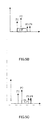
- FIG.3 shows and explains an actual example of a case in which the difference between the maximum propagation delay and minimum propagation delay exceeds the width of a reception time window.
- propagation delay difference T (1, 3) - T (1, 1) is less than the reception window width, but power P1 of a channel response corresponding to delay T (1, 1) is smaller than power P3 of a channel response corresponding to delay T (1, 3).
- a method for adjusting an uplink time advancement amount in a communication system composed of a mobile terminal and a plurality of base stations, and this method includes: a step of that plurality of base stations measuring propagation delay T (i, j) and channel response power P (i, j) from a mobile terminal to that plurality of base stations (where T (i, j) represents a propagation delay from mobile terminal i to base station j, P (i, j) represents channel response power from mobile terminal i to base station j, and i and j are natural numbers); a step of a non-serving station among that plurality of base stations reporting that measured propagation delay and power to a serving station; and a step of that serving station deciding an uplink time advancement amount of that mobile terminal based on that received propagation delay and power and propagation delay and power measured by that serving station itself, and reporting that time advancement amount to that mobile terminal.
- that method further includes: a step of that non-serving station comparing that measured propagation delay T (i, j) and propagation delay T' (i, j) previously measured by that non-serving station and determining whether or not an obtained first difference value is larger than a first predetermined threshold value, and/or comparing measured current power P (i, j) and previously measured power P' (i, j) and determining whether or not an obtained second difference value is larger than a second predetermined threshold value; and a step of that non-serving station reporting that measured propagation delay T (i, j) and power P (i, j) to that serving station according to a first difference value being larger than a first predetermined threshold value or a second difference value being larger than a second predetermined threshold value.
- that method further includes: a step of that serving station reporting propagation delay T (i, j) and power P (i, j) measured beforehand by each base station, stored by itself, to that non-serving station, and that non-serving station deciding a first time advancement amount of a system based on received propagation delay and power and propagation delay T (i, j) and power P (i, j) measured beforehand by itself; a step of that non-serving station deciding a second time advancement amount based on propagation delay Tn (i, j) and power Pn (i, j) newly measured by itself and that received propagation delay T (i, j) and power P (i, j) measured by another base station, and determining whether or not a difference value between a first time advancement amount and second time advancement amount is larger than a third predetermined threshold value, or determining whether or not a difference value between total received power obtained using a first time advancement amount and total received power obtained using a second time advancement amount is larger than
- that method further includes: a step of that serving station deciding a time advancement amount based on propagation delay and power received from that non-serving station and propagation delay and power measured by itself, and determining whether or not a difference value between that time advancement amount and a previously decided time advancement amount is larger than a sixth predetermined threshold value; and a step of that serving station reporting that time advancement amount to that mobile terminal according to a difference value between that time advancement amount and that previously decided time advancement amount being larger than that sixth predetermined threshold value.
- that method further includes: a step of a plurality of base stations measuring respectively current propagation delay Tn (i, j) and power Pn (i, j) of that mobile terminal; a step of that non-serving station calculating a first difference value between current propagation delay Tn (i, j) measured by itself and that propagation delay T (i, j), and a second difference value between that current power Pn (i, j) and that power P (i, j), and reporting each difference value to that serving station; and a step of that serving station adding together a received first difference value and that propagation delay T (i, j) measured by that non-serving station and acquiring current propagation delay Tn (i, j) of that non-serving station, adding together a received second difference value and that power P (i, j) of that non-serving station and acquiring current power Pn (i, j) of that non-serving station, deciding a new time advancement amount based on respective current propagation delay
- that function F() decides a time advancement amount that maximizes the power of a signal positioned within a reception window.
- that function F() decides a time advancement amount that maximizes the diversity gain of a signal positioned within a reception window.
- a quantization interval of that time advancement amount transmitted to that mobile terminal from a serving station via an air-interface is configurable.
- a method for adjusting an uplink time advancement amount in a communication system composed of a mobile terminal and a plurality of base stations, and that method includes: a step of that plurality of base stations measuring propagation delay T (i, j) and channel response power P (i, j) from a mobile terminal to that plurality of base stations (where T (i, j) represents a propagation delay from mobile terminal i to base station j, P (i, j) represents channel response power from mobile terminal i to base station j, and i and j are natural numbers); a step of a non-serving station among that plurality of base stations reporting that measured propagation delay and power to a serving station; a step of that serving station deciding which base station configures a coordination area based on that received propagation delay and power, and reporting that coordination area to a terminal and all non-serving stations that transmitted a measurement report; and a step of that serving station deciding an uplink time advancement amount of that mobile terminal
- a step of that non-serving station comparing that measured propagation delay T (i, j) and propagation delay T' (i, j) previously measured by that non-serving station and determining whether or not an obtained first difference value is larger than a first predetermined threshold value, and/or comparing measured current power P (i, j) and previously measured power P' (i, j) and determining whether or not an obtained second difference value is larger than a second predetermined threshold value; and a step of that non-serving station reporting that measured propagation delay T (i, j) and power P (i, j) to that serving station according to a first difference value being larger than a first predetermined threshold value or a second difference value being larger than a second predetermined threshold value.
- a step of a plurality of base stations measuring respectively current propagation delay Tn (i, j) and power Pn (i, j) of that mobile terminal; a step of that non-serving station calculating a first difference value between current propagation delay Tn (i, j) measured by itself and that propagation delay T (i, j), and a second difference value between that current power Pn (i, j) and that power P (i, j), and reporting each difference value to that serving station; and a step of that serving station adding together a received first difference value and that propagation delay T (i, j) measured by that non-serving station and acquiring current propagation delay Tn (i, j) of that non-serving station, and adding together a received second difference value and that power P (i, j) of that non-serving station and acquiring current power Pn (i, j) of that non-serving station.
- a method for adjusting an uplink time advancement amount in a communication system composed of a mobile terminal and a plurality of base stations, and this method includes: a step of that mobile terminal measuring propagation delay from itself to each non-serving station among that plurality of base stations, and reporting measured propagation delay to a serving station; a step of each non-serving station measuring only channel response power of a mobile terminal, and reporting measured power to that serving station; a step of that serving station deciding a time advancement amount based on propagation delay received from a mobile terminal, power information received from a non-serving station, and propagation delay and power measured by a serving station itself; and a step of that serving station reporting that time advancement amount to that mobile terminal.
- that method further includes: a step of that non-serving station comparing respectively measured current power and power previously measured by that station itself, determining whether or not a compared first difference value is larger than one first predetermined threshold value, and reporting current power measured by that non-serving station to that serving station according to that first difference value being larger than that first predetermined threshold value; and a step of that serving station comparing a decided time advancement amount and a previously decided time advancement amount, determining whether or not a compared second difference value is larger than one second predetermined threshold value, and that serving station reporting that time advancement amount to a mobile terminal according to that second difference value being larger than a second predetermined threshold value.
- an apparatus for adjusting an uplink time advancement amount in a mobile communication system is located in a serving station and includes: a measurement section that measures propagation delay and channel response power from a mobile terminal to a serving station; a transmission/reception section that receives from a non-serving station propagation delay and channel response power from that mobile terminal to that non-serving station; and a time advancement amount deciding section that decides a time advancement amount based on propagation delay and channel response power measured by that measurement section, and propagation delay and channel response power received from that non-serving station; wherein that transmission/reception section transmits a decided time advancement amount to that mobile terminal.
- that apparatus further includes a calculation section that determines whether or not a difference value between a decided time advancement amount and a previously decided time advancement amount is larger than a predetermined threshold value; wherein the transmission/reception section reports that time advancement amount to that mobile terminal according to a difference value between that time advancement amount and that previously decided time advancement amount being larger than a predetermined threshold value.
- that calculation section compares measured propagation delay and previously measured propagation delay and determines whether or not an obtained first difference value is larger than a first predetermined threshold value, and/or compares measured channel response power and previously measured power and determines whether or not an obtained second difference value is larger than a second predetermined threshold value; and that transmission/reception section transmits that propagation delay and channel response power to a serving station according to a first difference value being larger than a first predetermined threshold value or a second difference value being larger than a second predetermined threshold value.
- that function F() decides a time advancement amount that maximizes the power of a signal positioned within a reception window.
- that function F() decides a time advancement amount that maximizes the diversity gain of a signal positioned within a reception window.
- the present invention provides a new time advancement amount adjustment method and apparatus that enable uplink multipoint reception link performance to be improved.
- the effective power of uplink multiple-base-station reception can be optimized, and interference power is effectively reduced.
- FIG.4 is a diagrammatic representation of the signaling flow according to Embodiment 1 of the present invention.
- base stations eNB 1, eNB 2, and eNB 3 measure respectively propagation delays T (1,1), T (1, 2), and T (1, 3), and channel response powers P (1, 1), P (1, 2), and P (1, 3), from mobile terminal UE 1, after which measured propagation delays T (1, 1) and T (1, 3) and channel response powers P (1, 1), P (1, 2), and P (1, 3) are reported to serving station eNB 2 by non-serving stations eNB 1 and eNB 3, and then serving station eNB 2 measures an uplink time advancement amount of that mobile terminal based on received delay and power information, and propagation delay and power information measured by itself, after which serving station eNB 2 reports a decided time advancement amount to mobile terminal UE 1.
- serving station eNB 2 calculates a time advancement amount in accordance with equation 2 below.
- TA i F T i j , P i j
- F() represents a function that decides a time advancement amount.
- P (i, j) is channel response power from mobile terminal i to base station j, where i and j are natural numbers.
- time advancement amount TA (i) is no more than a function of different (channel) propagation delays
- time advancement amount TA (i) is a function of different propagation delays and channel response powers.
- non-serving stations eNB 1 and eNB 3 need only report measured channel propagation delay to serving station eNB 2, whereas in FIG.4 according to Embodiment 1 of the present invention, it is necessary for non-serving stations eNB 1 and eNB 3 to report corresponding channel response power as well as reporting propagation delay.
- a method of deciding function F() can be to select time advancement amount TA (i) such that function F() maximizes the power of a signal positioned within a reception window. If time advancement amount TA (i) is decided using this kind of function F(), it is possible for the effect of time advancement amount TA (i) to be improved as shown in FIG.5A .
- FIG.5A through FIG.5C are diagrammatic representations of time advancement amounts decided by embodiments of the present invention.
- T2 is not the minimum propagation delay, but with time advancement amount TA (i) shown in FIG.5A , if the difference between the maximum propagation delay and minimum propagation delay exceeds reception time window width CP, signal P3 having higher power can enter into a reception window of a base station, and therefore the problem of a high-power signal not being accommodated in a base station's reception window, and furthermore of interference being caused, as seen with conventional technology, is solved.
- FIG.5B is a diagrammatic representation of a time advancement amount decided according to another embodiment of the present invention.
- the relationship between different delayed signal powers is P1>P3-E-P4, but the difference value between P1 and P3+P4 is not large.
- the value of TA (i) shown in FIG.5B should be able to be used.
- FIG.6 is a diagrammatic representation of related sections in a base station arranged according to one embodiment of the present invention.
- base station apparatus 600 may include central processing unit (CPU) 601 that executes various kinds of system software and application software, processes various kinds of data, and controls the operation of each section within base station apparatus 600, read-only memory (ROM) 602 that stores various kinds of programs necessary for CPU 601 to perform various kinds of processing and control, random access memory (RAM) 603 that stores intermediate data generated incidentally in the process of processing and control by CPU 601, transmission/reception section 604 that is connected to a radio network (not shown) via an antenna (not shown), and transmits and receives various kinds of data and signaling between base station apparatus 600 and mobile terminal UEs, and storage section 605 that stores various kinds of received and/or transmitted data and signaling.
- CPU central processing unit
- ROM read-only memory
- RAM random access memory
- transmission/reception section 604 that is connected to a radio network (not shown) via an antenna (not shown), and transmits and receives various kinds of data and signaling between base station apparatus 600 and mobile terminal UEs
- storage section 605 that stores various kinds
- Base station apparatus 600 further includes measurement section 606, calculation section 607, time advancement amount deciding section 608, and/or user interface section 609.
- CPU 601 controls the above sections and accomplishes various kinds of functions and operations by executing a control function by execution of a corresponding control program.
- the above sections are mutually connected by bus line 610.
- above base station apparatus 600 does not limit the scope of the present invention and is no more than an illustrative description, and a number of sections may be omitted, the functions of a number of sections may be executed in an amalgamated fashion by a single section, and/or the functions of a number of sections may be executed divided among a smaller plurality of sections.
- a plurality of base stations may be included in a communication system according to an embodiment of the present invention, and each base station may be provided with the same configuration as described above.
- suffix "-1" is appended to the reference code of each section, so that the measurement section is represented by 606-1, for example, for each section in base station eNB 2
- suffix "-2" is appended to the reference code of each section, so that the measurement section is represented by 606-2
- suffix "-3" is appended to the reference code of each section, so that the measurement section is represented by 606-3, for example, and likewise for other cases.
- measurement sections 606-1, 606-2, and 606-3 of base stations eNB 1, eNB 2, and eNB 3 measure respectively propagation delays T (1, 1), T (1, 2), and T (1, 3) and channel response powers P (1, 1), P (1, 2), and P (1, 3) from mobile terminal UE 1 to the respective base station, and store each measured data in storage sections 605-1, 605-2, and 605-3 of the respective base station itself, transmission/reception sections 604-1 and 604-3 of non-serving stations eNB 1 and eNB 3 transmit powers P (1, 1) and P (1, 3) to serving station eNB 2, time advancement amount deciding section 608-2 of serving station eNB 2 decides an uplink time advancement amount of that mobile terminal based on equation 2 shown above, based on received delay and power information and propagation delay and power information measured by itself, and finally, transmission/reception section 604-2 of serving station eNB 2 reports a decided time advancement
- Embodiment 1 there may be a problem of signaling overhead when a non-serving station reports delay and power information to a serving station.
- a method according to an embodiment of the present invention it is necessary for irregular power information to be transmitted between base stations, and this increases signaling overhead, and since the time advancement amount is updated periodically, the increase in signaling overhead then increases the system load.
- the embodiment below is presented, in which signaling overhead caused by information transmission between base stations is reduced, and an advantageous effect of the present invention is achieved.
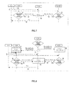
- FIG.7 is a diagrammatic representation of the signaling flow according to Embodiment 2 of the present invention.
- step ST01 mobile terminal UE 1 propagation delays T (1, 1), T (1, 2), and T (1, 3) and channel response powers P (1, 1), P (1, 2), and P (1, 3) are measured respectively by measurement sections 606-1, 606-2, and 606-3 of base stations eNB 1, eNB 2, and eNB 3, and then the flow proceeds to step ST02.
- step ST02 calculation sections 607-1 and 607-3 of non-serving stations eNB 1 and eNB 3 compare measured current propagation delay T (i, j) and power P (i, j) with propagation delay T' (i, j) and power P' (i, j) previously measured by those non-serving stations eNB 1 and eNB 3, and determine whether or not the comparison difference value is larger than a predetermined threshold value.
- calculation section 607-1 of non-serving station eNB 1 calculates the value of
- step ST03 transmission/reception sections 604-1 and 604-3 of non-serving stations eNB 1 and eNB 3 report measured current propagation delays T (1, 1) and T (1, 3) and current powers P (1, 1) and P (1, 3) to serving station eNB 2, and then the flow proceeds to step ST04.
- time advancement amount deciding section 608-2 of serving station eNB 2 decides uplink time advancement amount TA (i) of the relevant mobile terminal based on received propagation delay and power information and propagation delay and channel response power measured by itself, and then the flow proceeds to step ST05.
- the method whereby time advancement amount deciding section 608-2 of serving station eNB 2 decides time advancement amount TA (i) is similar to the method in Embodiment 1, and will not be described again here.
- step ST05 transmission/reception section 604-2 of serving station eNB 2 transmits decided time advancement amount TA (i) to mobile terminal UE 1.
- Embodiment 2 The distinction between Embodiment 2 and Embodiment 1 lies in the diamond-shaped block parts in FIG.7 -- that is, step ST02.
- the function of these diamond-shaped blocks in Embodiment 2 is threshold value determination, and after a non-serving station has periodically measured new propagation delay and power, these are not reported immediately to the serving station, but instead, threshold value determination is first performed, and measured values are only reported to the serving station after a certain condition is satisfied.
- reporting is performed based on an event trigger
- Embodiment 1 reporting is performed based on a time trigger or periodically. Therefore, event trigger based Embodiment 2 effectively reduces unnecessary reporting from a non-serving station to a serving station.
- Embodiment 2 there are two conditions for times for triggering a report.
- the first condition is that the difference between an original propagation delay measured value and a new channel measured value is larger than ⁇ T/2
- the second condition is that the difference between an original channel response power measured value and a new channel response power measured value is larger than ⁇ P/N, where N is the number of multipoint reception base stations, and ⁇ T and ⁇ P are parameters set by the system beforehand. If either of these two conditions is satisfied, an event is triggered.
- Embodiment 2 of the present invention enables signaling overhead between base stations to be effectively reduced.
- FIG.8 is a diagrammatic representation of the signaling flow according to Embodiment 3 of the present invention.
- step ST01 in a method of adjusting an uplink time advancement amount according to Embodiment 3 of the present invention, in step ST01, if one predetermined condition (a threshold value determination condition "Is the threshold value exceeded?" is possible as in step ST04 in Embodiment 5 described later herein) is satisfied, transmission/reception section 604-2 of serving station eNB 2 reports all propagation delay and power information to non-serving stations eNB 1 and eNB 3.
- transmission/reception section 604-2 of serving station eNB 2 reports stored propagation delay and power information measured beforehand by all related base stations to a non-serving station.
- propagation delays T (1, 2) and T (1, 3) and channel response powers P (1, 2) and P (1, 3) are reported to non-serving station eNB 1, and propagation delays T (1, 1) and T (1, 2) and channel response powers P (1, 1) and P(1, 2) are reported to non-serving station eNB 3.
- the flow proceeds to step ST02.
- step ST02 time advancement amount deciding sections 608-1 and 608-3 of non-serving stations eNB 1 and eNB 3 decide a system time advancement amount for that time based on received propagation delay and power information and propagation delay and power information measured beforehand by those stations.
- time advancement amount deciding sections 608-1 and 608-3 of non-serving stations eNB 1 and eNB 3 decide a time advancement amount using the same kind of method as serving station eNB 2 -- that is, using equation 2 in Embodiment 1.
- the flow proceeds to step ST03.
- step ST03 measurement sections 606-1, 606-2, and 606-3 of base stations eNB 1, eNB 2, and eNB 3 each measure new propagation delay and power information, and represent these items of information as Tn and Pn. That is to say, measurement section 606-1 of non-serving station eNB 1 measures new propagation delay Tn (1, 1) and new channel response power Pn (1, 1), measurement section 606-3 of non-serving station eNB 3 measures new propagation delay Tn (1, 3) and new channel response power Pn (1, 3), and measurement section 606-2 of serving station eNB 2 measures new propagation delay Tn (1, 2) and new channel response power Pn (1, 2). Following this, the flow proceeds to step ST04.
- time advancement amount deciding sections 608-1 and 608-3 of non-serving stations eNB 1 and eNB 3 decide a "new" time advancement amount based on new propagation delay and power information measured by measurement sections 606-1 and 606-3 of those stations, and perform event determination.
- a "new" time advancement amount is obtained based on propagation delay and power information newly measured by those stations (eNB 1 and eNB 3), and old measurement information (propagation delay and power) of another base station previously obtained from serving station eNB 2.
- the method whereby time advancement amount deciding section 608 of a non-serving station decides a time advancement amount is similar to the method used in Embodiment 1.
- calculation sections 607-1 and 607-3 of non-serving stations eNB 1 and eNB 3 compare a decided current time advancement amount and total received power obtained using a current time advancement amount with a time advancement amount previously decided by those non-serving stations eNB 1 and eNB 3 and total received power obtained using that time advancement amount, and determine whether or not the comparison difference value is larger than a predetermined threshold value.
- Non-serving station eNB 3 also executes the same kind of operation as non-serving station eNB 3 .
- TAn (1, 1) a current time advancement amount decided by time advancement amount deciding section 608-1 of non-serving station eNB 1
- TA (1, 1) a previous time advancement amount is TA (1, 1)
- calculation section 607-1 of non-serving station eNB 1 calculates the value of
- a trigger event is defined as two conditions, the first condition being that a difference value of time advancement amounts obtained in step ST02 and step ST04 is larger than ⁇ T, and the second condition being that a difference value of total power obtained using two time advancement amounts is larger than ⁇ P. If either the first condition or the second condition is satisfied, an event is triggered.
- the definitions of ⁇ T and ⁇ P are similar to the definitions given in Embodiment 2.
- step ST05 transmission/reception sections 604-1 and 604-3 of non-serving stations eNB 1 and eNB 3 report measured current propagation delay Tn (1, 1) and/or Tn (1, 3) and current power Pn (1, 1) and/or Pn (1, 3) to serving station eNB 2, and then the flow proceeds to step ST06.
- step ST06 time advancement amount deciding section 608-2 of serving station eNB 2 decides new uplink time advancement amount TAn (i) based on received propagation delay and power information and propagation delay and power measured by itself. Following this, the flow proceeds to step ST07.
- step ST07 transmission/reception section 604-2 of serving station eNB 2 transmits decided new time advancement amount TAn (i) to mobile terminal UE 1.
- time advancement amount deciding section 608-2 of serving station eNB 2 decides time advancement amount TAn (i) in step ST06 is similar to the method in Embodiment 1, and will not be described again here.
- Embodiment 3 of the present invention enables signaling overhead between base stations to be effectively reduced.
- FIG.9 is a diagrammatic representation of the signaling flow according to Embodiment 4 of the present invention.
- T (i, j) represents a propagation delay from mobile terminal i to base station j
- P (i, j) represents channel response power from mobile terminal i to base station j
- new parameter TP (i, j) is equivalent to performing weighting on propagation delay using power.
- transmission/reception section 604-2 of serving station eNB 2 can directly provide a minimum TP (i, j) to non-serving stations eNB 1 and eNB 3 as an event trigger reference. Following this, the flow proceeds to step ST02.
- step ST02 measurement sections 606-1, 606-2, and 606-3 of base stations eNB 1, eNB 2, and eNB 3 each measure new propagation delay and power information, and represent these items of information as Tn and Pn. That is to say, measurement section 606-1 of non-serving station eNB 1 measures new propagation delay Tn (1, 1) and new channel response power Pn (1, 1), measurement section 606-3 of non-serving station eNB 3 measures new propagation delay Tn (1, 3) and new channel response power Pn (1, 3), and measurement section 606-2 of serving station eNB 2 measures new propagation delay Tn (1, 2) and new channel response power Pn (1, 2). Following this, the flow proceeds to step ST03.
- a non-serving station configures an event using newly measured propagation delay and power information, that event being defined as
- calculation section 607-1 of non-serving station eNB 1 calculates Tn (1, 1)/Pn (1, 1) and determines whether or not a difference value between value Tn (1, 1)/Pn (1, 1) and min ⁇ TP (i, j) ⁇ is larger than predetermined threshold value ⁇ Tp
- calculation section 607-3 of non-serving station eNB 3 calculates Tn (1, 3)/Pn (1, 3) and determines whether or not a difference value between value Tn (1, 3)/Pn (1, 3) and min ⁇ TP (i, j) ⁇ is larger than predetermined threshold value ⁇ Tp.
- step ST04 transmission/reception section 604-1 and/or 604-3 of non-serving stations eNB 1 and/or eNB 3 for which a condition is satisfied report measured current propagation delay Tn (1, 1) and/or Tn (1, 3) and current power Pn (1, 1) and/or Pn (1, 3) to serving station eNB 2, and then the flow proceeds to step ST05.
- step ST05 time advancement amount deciding section 608-2 of serving station eNB 2 decides new uplink time advancement amount TAn (i) based on received propagation delay and power information and propagation delay and power measured by itself. Following this, the flow proceeds to step ST06.
- step ST06 transmission/reception section 604-2 of serving station eNB 2 transmits decided new time advancement amount TAn (i) to mobile terminal UE 1.
- time advancement amount deciding section 608-2 of serving station eNB 2 decides time advancement amount TAn (i) in step ST05 is similar to the method in Embodiment 1, and will not be described again here.
- Embodiment 4 of the present invention information transmission from a serving station to a non-serving station is greatly compressed, and an event trigger determination process within a non-serving station is simplified.
- FIG.10 is a diagrammatic representation of the signaling flow according to Embodiment 5 of the present invention.
- step ST01 measurement sections 606-1, 606-2, and 606-3 of base stations eNB 1, eNB 2, and eNB 3 measure respectively mobile terminal UE 1 propagation delays T (1, 1), T (1, 2), and T (1, 3), and channel response powers P (1, 1), P (1, 2), and P (1, 3).
- step ST02. measurement sections 606-1, 606-2, and 606-3 of base stations eNB 1, eNB 2, and eNB 3 measure respectively mobile terminal UE 1 propagation delays T (1, 1), T (1, 2), and T (1, 3), and channel response powers P (1, 1), P (1, 2), and P (1, 3).
- step ST02 transmission/reception sections 604-1 and 604-3 of non-serving stations eNB 1 and eNB 3 report measured propagation delays T (1, 1) and T (1, 3) and powers P (1, 1) and P (1, 3) to serving station eNB 2. Following this, the flow proceeds to step ST03.
- step ST03 time advancement amount deciding section 608-2 of serving station eNB 2 decides uplink time advancement amount TA (i) based on received propagation delay and power information and propagation delay and channel response power information measured by measurement section 606-2 of serving station eNB 2. Following this, the flow proceeds to step ST04.
- step ST04 calculation section 607-2 of serving station eNB 2 compares decided time advancement amount TA (i) with previously decided time advancement amount TA'(i), and determines whether or not the comparison difference value is larger than predetermined threshold value AT. If the comparison difference value is determined to be larger than predetermined threshold value AT, the flow proceeds to step ST05.
- step ST05 transmission/reception section 604-2 of serving station eNB 2 reports decided time advancement amount TA (i) to mobile terminal UE 1.
- Embodiment 5 The main distinction between Embodiment 5 and Embodiment 1 is that event determination is performed after a serving station obtains a time advancement amount, and a new time advancement amount is only reported to a mobile terminal when an event is satisfied. In this way, a number of unnecessary time advancement amount updates are avoided on an air-interface.
- FIG.11 is a diagrammatic representation of the signaling flow according to Embodiment 6 of the present invention.
- step STO1 mobile terminal UE 1 propagation delays T (1, 1), T (1, 2), and T (1, 3) and channel response powers P (1, 1), P (1, 2), and P (1, 3) are measured respectively by measurement sections 606-1, 606-2, and 606-3 of base stations eNB 1, eNB 2, and eNB 3, and then the flow proceeds to step ST02.
- step ST02 calculation sections 607-1 and 607-3 of non-serving stations eNB 1 and eNB 3 compare measured current propagation delay and power with propagation delay and power previously measured by those non-serving stations eNB 1 and eNB 3, and determine whether or not the comparison difference value is larger than a predetermined threshold value.
- calculation section 607-1 of non-serving station eNB 1 calculates the value of
- step ST03 transmission/reception sections 604-1 and 604-3 of non-serving stations eNB 1 and eNB 3 report measured current propagation delays T (1, 1) and T (1, 3) and current powers P (1, 1) and P (1, 3) to serving station eNB 2, and then the flow proceeds to step ST04.
- time advancement amount deciding section 608-2 of serving station eNB 2 decides new time advancement amount TA (i) based on received propagation delay and power information and propagation delay and channel response power measured by itself.
- the method whereby time advancement amount deciding section 608-2 of serving station eNB 2 decides time advancement amount TA (i) is similar to the method in Embodiment 1. Following this, the flow proceeds to step ST05.
- step ST05 calculation section 607-2 of serving station eNB 2 compares measured time advancement amount TA (i) with previously decided time advancement amount TA'(i), and determines whether or not the comparison difference value is larger than predetermined threshold value AT. If the comparison difference value is determined to be larger than predetermined threshold value AT, the flow proceeds to step ST06.
- step ST06 transmission/reception section 604-2 of serving station eNB 2 transmits decided time advancement amount TA (i) to mobile terminal UE 1.
- Embodiment 6 The main distinction between Embodiment 6 and Embodiment 2 is that event determination is performed after a serving station obtains a time advancement amount, and a new time advancement amount is only reported to a mobile terminal when an event is satisfied. In this way, a number of unnecessary time advancement amount updates are avoided on an air-interface.
- FIG.12 is a diagrammatic representation of the signaling flow according to Embodiment 7 of the present invention.
- step ST01 measurement sections 606-1, 606-2, and 606-3 of base stations eNB 1, eNB 2, and eNB 3 measure respectively mobile terminal UE 1 propagation delays T (1, 1), T (1, 2), and T (1, 3), and channel response powers P (1, 1), P (1, 2), and P (1, 3).
- step ST02. measurement sections 606-1, 606-2, and 606-3 of base stations eNB 1, eNB 2, and eNB 3 measure respectively mobile terminal UE 1 propagation delays T (1, 1), T (1, 2), and T (1, 3), and channel response powers P (1, 1), P (1, 2), and P (1, 3).
- step ST02 transmission/reception sections 604-1 and 604-3 of non-serving stations eNB 1 and eNB 3 report measured propagation delays T (1, 1) and T (1, 3) and powers P (1, 1) and P (1, 3) to serving station eNB 2. Following this, the flow proceeds to step ST03.
- time advancement amount deciding section 608-2 of serving station eNB 2 decides new time advancement amount TA (i) based on received propagation delay and power information and propagation delay and power information measured by itself, and reports decided new time advancement amount TA (i) to mobile terminal UE 1 by means of transmission/reception section 604-2.
- step ST04 the measurement sections of base stations eNB 1, eNB 2, and eNB 3 repeat the operation of step ST01. That is to say, mobile terminal UE 1 current propagation delays Tn (1, 1), Tn (1, 2), and Tn (1, 3) and channel response powers Pn (1, 1), Pn (1, 2), and Pn (1, 3) are measured respectively. Following this, the flow proceeds to step ST05.
- step ST05 calculation section 607-1 of non-serving station eNB 1 calculates difference value
- Calculation section 607-3 of non-serving station eNB 3 calculates difference value
- step ST06 calculation section 607-2 of serving station eNB 2 performs calculation based on received respective difference values and previous respective propagation delay and power values, and obtains a respective current propagation delay and power. Specifically, calculation section 607-2 of serving station eNB 2 adds together received difference value
- time advancement amount deciding section 608-2 of serving station eNB 2 decides new time advancement amount TA (i) based on obtained current propagation delays Tn (1, 1), Tn (1, 2), and Tn (1, 3) and channel response powers Pn (1, 1), Pn (1, 2), and Pn (1, 3), and reports decided new time advancement amount TAn (i) to mobile terminal UE 1 by means of transmission/reception section 604-2.
- the method whereby time advancement amount deciding section 608-2 of serving station eNB 2 decides time advancement amount TAn (i) is similar to the method in Embodiment 1, and will not be described again here.
- Embodiment 8 is presented in order to improve the accuracy of delay measurement.
- Embodiment 8 while downlink channel delay is measured by a mobile terminal and reported directly to a serving station, a non-serving station need only measure a power value and report this to a serving station.
- uplink delay and downlink delay can be regarded as symmetrical, while uplink channel response power and downlink channel response power are generally asymmetrical. Consequently, it is possible for a mobile terminal to measure only propagation delay.
- a measurement section (not shown) that measures propagation delay from that mobile terminal to a base station
- a transmission/reception section (not shown) that receives various kinds of data and signaling from a base station.
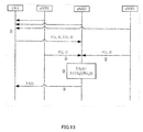
- FIG.13 is a diagrammatic representation of the signaling flow according to Embodiment 8 of the present invention.
- step ST01 a measurement section (not shown) of mobile terminal UE 1 measures propagation delays T (1, 1) and T (1, 3) from that mobile terminal to non-serving stations eNB 1 and eNB 3, and a transmission/reception section (not shown) reports measured propagation delays T (1, 1) and T (1, 3) to serving station eNB 2.
- step ST02. a measurement section (not shown) of mobile terminal UE 1 measures propagation delays T (1, 1) and T (1, 3) from that mobile terminal to non-serving stations eNB 1 and eNB 3, and a transmission/reception section (not shown) reports measured propagation delays T (1, 1) and T (1, 3) to serving station eNB 2.
- step ST02 measurement sections 606-1 and 606-3 of non-serving stations eNB 1 and eNB 3 measure only mobile terminal UE 1 channel response powers P (1, 1) and P (1, 3), and report measured powers P (1, 1) and P (1, 3) to serving station eNB 2 by means of transmission/reception sections 604-1 and 604-3, after which the flow proceeds to step ST03.
- time advancement amount deciding section 608-2 of serving station eNB 2 decides time advancement amount TA (i) based on propagation delays T (1, 1) and T (1, 3) received from mobile terminal UE 1, power information P (1, 1) and P (1, 3) received from non-serving stations eNB 1 and eNB 3, and propagation delay T (1, 2) and power P (1, 2) measured by serving station eNB 2 itself.
- the method whereby time advancement amount deciding section 608-2 of serving station eNB 2 decides time advancement amount TA (i) is similar to the method in Embodiment 1, and will not be described again here. Following this, the flow proceeds to step ST04.
- step ST04 transmission/reception section 604-2 of serving station eNB 2 reports time advancement amount TA (i) to mobile terminal UE 1.
- Embodiment 8 of the present invention enables signaling overhead between base stations to be effectively reduced.
- a measurement section (not shown) that measures propagation delay from that mobile terminal to a base station
- a transmission/reception section (not shown) that receives various kinds of data and signaling from a base station.
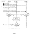
- FIG.14 is a diagrammatic representation of the signaling flow according to Embodiment 9 of the present invention.
- step ST01 a measurement section (not shown) of mobile terminal UE 1 measures propagation delays T (1, 1) and T (1, 3) from that mobile terminal to non-serving stations eNB 1 and eNB 3, and a transmission/reception section (not shown) reports measured propagation delays T (1, 1) and T (1, 3) to serving station eNB 2.
- step ST02. a measurement section (not shown) of mobile terminal UE 1 measures propagation delays T (1, 1) and T (1, 3) from that mobile terminal to non-serving stations eNB 1 and eNB 3, and a transmission/reception section (not shown) reports measured propagation delays T (1, 1) and T (1, 3) to serving station eNB 2.
- step ST02 measurement sections 606-1 and 606-3 of non-serving stations eNB 1 and eNB 3 measure only mobile terminal UE 1 channel response powers P (1, 1) and P (1, 3), and calculation sections 607-1 and 607-3 of non-serving stations eNB 1 and eNB 3 compare measured current power with power previously measured by those non-serving stations eNB 1 and eNB 3, and determine whether or not the comparison difference value is larger than a predetermined threshold value.
- Non-serving station eNB 3 also executes the same kind of operation as non-serving station eNB 1.
- step ST03 transmission/reception sections 604-1 and 604-3 of non-serving stations eNB 1 and eNB 3 report measured current powers P (1, 1) and P (1, 3) to serving station eNB 2, and then the flow proceeds to step ST04.
- time advancement amount deciding section 608-2 of serving station eNB 2 decides time advancement amount TA (i) based on propagation delays T (1, 1) and T (1, 3) received from mobile terminal UE 1, power information P (1, 1) and P (1, 3) received from non-serving stations eNB 1 and eNB 3, and propagation delay T (1, 2) and power P (1, 2) measured by measurement section 606-2 of serving station eNB 2 itself.
- the method whereby time advancement amount deciding section 608-2 of serving station eNB 2 decides time advancement amount TA (i) is similar to the method in Embodiment 1, and will not be described again here. Following this, the flow proceeds to step ST05.
- step ST05 calculation section 607-2 of serving station eNB 2 compares decided time advancement amount TA (i) with previously decided time advancement amount TA'(i), and determines whether or not the comparison difference value is larger than predetermined threshold value AT. If the comparison difference value is determined to be larger than predetermined threshold value AT, the flow proceeds to step ST06.
- step ST06 transmission/reception section 604-2 of serving station eNB 2 reports decided new time advancement amount TA (i) to mobile terminal UE 1.
- Embodiment 9 of the present invention enables signaling overhead between base stations to be effectively reduced.
- the quantization interval is related to parameter ⁇ T set within the base station system.
- a quantization interval of a time advancement amount transmitted on an air-interface is fixed.
- system parameter ⁇ T of each embodiment of the present invention is configurable, and therefore a corresponding time advancement amount quantization interval is also configurable.
- a system according to an embodiment of the present invention can represent 15 ms by performing automatic arrangement of 4-bit transmitted numeric value 15 (the quantization interval being 1 at this time), or represent 15 ms by performing automatic arrangement of 3-bit transmitted numeric value 5 (the quantization interval being 3 at this time), or represent 15 ms by performing automatic arrangement of 2-bit transmitted numeric value 3 (the quantization interval being 5 at this time), according to the actual conditions. If a time advancement amount is transmitted using a large quantization interval, fewer bits can be used, enabling signaling overhead between base stations to be reduced.
- transmission between base stations of signaling relating to power and propagation delay can be used in an uplink coordination area (UP CoMP set) decision.
- UP CoMP set uplink coordination area
- FIG.15 is a diagrammatic representation of the signaling flow according to Embodiment 11 of the present invention.
- a CoMP set decision is divided into the following steps.
- non-serving stations eNB 1, eNB 3, and eNB 4 report (channel) propagation delay and channel response power from mobile terminal UE 1 to each base station to serving station eNB 2, and in step ST02, serving station eNB 2 decides which base stations configure a CoMP set based on the received propagation delay and power data. For example, different combinations are decided such as eNB 1 and eNB 3 configuring a CoMP set or eNB 1 and eNB 4 configuring a CoMP set.
- serving station eNB 2 reports the CoMP set decision to mobile terminal UE 1 and all non-serving stations eNB 1, eNB 3, and eNB 4 that transmitted a measurement report.
- serving station eNB 2 also decides a mobile terminal UE 1 uplink time advancement amount based on propagation delay and power received from each non-serving station configuring a CoMP set, and propagation delay and power measured by serving station eNB 2 itself, and reports the decided time advancement amount to that mobile terminal UE 1.
- Embodiments 2 through 4 and Embodiment 7 can be similarly applied in an improvement of Embodiment 11, and will not be described again here.
- Embodiment 11 emphasizes a CoMP set decision
- Embodiments 2 through 4 emphasize TA adjustment, but the requirements for signaling transmission between base stations in Embodiment 11 and Embodiment 1 are similar -- that is, uplink propagation delay and power information may be used in a time advancement amount decision, and may be used in a UP CoMP set decision. Therefore, the methods described in Embodiments 2 through 4 and Embodiment 7 can be applied directly to Embodiment 11.
- Embodiments of the present invention can be implemented by means of hardware, software, firmware, or a method combining these, but the implementation method does not limit the scope of the present invention.
Landscapes
- Engineering & Computer Science (AREA)
- Computer Networks & Wireless Communication (AREA)
- Signal Processing (AREA)
- Mobile Radio Communication Systems (AREA)
- Time-Division Multiplex Systems (AREA)
Abstract
A method and device for adjusting a timing advance in a communication system composed of a mobile terminal and multiple base stations is provided. The method includes steps: the multiple base stations measures channel latencies and powers of channel responses between the mobile terminal and the multiple base stations separately; the non-serving base station in the multiple base stations reports the channel latency and the power measured to a serving base station; and the serving base station determines the timing advance of the uplink of the mobile terminal according to the channel latency and the power received and the channel latency and the power which are measured by the serving base station itself, and informs the mobile base station of the timing advance. By using the method and the device, the useful power received by the uplink multi-base stations can be optimized, and the interference power can be effectively reduced.
Description
- The present invention relates to a technology for uplink synchronization and uplink multiple-base-station coordination in the communication field. More particularly, the present invention relates to time advancement amount adjustment in uplink multipoint reception in a mobile communication system.
- In an uplink of a radio communication system based on orthogonal frequency division multiplexing (OFDM) or time division multiple access (TDMA), there is one reception time window. In an orthogonal frequency division multiplexing system, this time window is a cyclic prefix, and in a time division multiple access system, this window is a guard interval. A transmission signal of a terminal is only correctly received and demodulated when it reaches a base station within a time window, and in other cases an arriving signal changes to interference, thereby degrading uplink performance.
- However, in an uplink there is propagation delay from a terminal to a base station, and uplink propagation delay must be compensated for in order to ensure that a terminal signal is able to reach the base station within a time window. In an actual radio communication system, uplink propagation delay is measured by a base station, this delay is reported to a terminal as a time advancement amount, and the terminal advances its own transmission timing by this time advancement amount, thereby compensating for terminal signal uplink propagation delay, and enabling a terminal signal to reach the base station at the start of a time window. Consequently, in a point-to-point uplink, a time advancement amount is set to uplink propagation delay.
- However, when a plurality of base stations perform coordinated reception of uplink signals, the situation becomes complicated.
FIG.1 shows the framework of a system in which a plurality of base stations perform coordinated reception of uplink signals. As shown inFIG. 1 , there are a plurality of base stations (three being shown here) and mobile stations (two being shown here), and it is assumed here that base station eNB 2 is the serving station of mobile terminals UE 1 andUE 2, time delays for the arrival of a signal transmitted bymobile terminal UE 1 at eNB 1, eNB 2, and eNB 3 are T (1, 1), T (1, 2), and T (1, 3), respectively, and time delays for the arrival of a signal transmitted bymobile terminal UE 2 ateNB 1, eNB 2, and eNB 3 are T (2, 1), T (2, 2), and T (2, 3), respectively. - Due to the effects of the actual communication environment, there is a possibility that none of the propagation delays with which a signal transmitted by a terminal reaches a plurality of receiving base stations will coincide, but a terminal can only change transmission timing in line with one time advancement amount, and calculation of this time advancement amount is an important factor affecting uplink performance. There are two conventional methods of setting a time advancement amount in such a situation, referred to here as
method 1 andmethod 2.Method 1 is to set a time advancement amount to an uplink propagation delay from a terminal to a serving station.Method 2 is to set a time advancement amount to the shortest of a plurality of propagation delays. - When
method 1 is used, or if the propagation delay from a terminal to a serving station is not the shortest delay, there is a terminal signal that arrives at a base station before a reception time window, and interference is caused. Whenmethod 2 is used, there is no terminal signal that arrives at a base station before a reception time window, andmethod 2 can ensure that all uplink signals reach a base station within a reception time window if the difference between the maximum propagation delay and minimum propagation delay does not exceed the width of the reception time window. Althoughmethod 1 andmethod 2 differ in the algorithms that actually set a time advancement amount, both are similar in terms of signaling flow. -
FIG.2 is a signaling flowchart showing an algorithm that sets a time advancement amount in conventional technology. As shown inFIG.2 , when three base stations eNB 1, eNB 2, and eNB 3 receive amobile terminal UE 1 signal, those three base stations each measure themobile terminal UE 1 propagation delay, and then coordinated reception base stations (non-serving stations) eNB 1 and eNB 3 report measured propagation delays T (1, 1) and T (1, 3) to serving station eNB 2, and serving station eNB 2 decides a time advancement amount based on the received propagation delays. The time advancement amount algorithm used by serving station eNB 2 can be generalized using one simple function.
- In
equation 1, TA (i) is a time advancement amount for terminal i, f() is a function that decides a time advancement amount, and T (i, j) is a propagation delay from terminal i to each base station j.Equation 1 explains that, with a conventional method, time advancement amount setting relates only to differences in propagation delay from a terminal to base stations. -
- NPL 1
3GPP TR 36.814 (2009-01) - However, if the difference between the maximum propagation delay and minimum propagation delay exceeds the width of a reception time window, a conventional method -- and
method 2, in particular -- is no longer desirable.FIG.3 shows and explains an actual example of a case in which the difference between the maximum propagation delay and minimum propagation delay exceeds the width of a reception time window. InFIG.3 , propagation delay difference T (1, 3) - T (1, 1) is less than the reception window width, but power P1 of a channel response corresponding to delay T (1, 1) is smaller than power P3 of a channel response corresponding to delay T (1, 3). If a time advancement amount is set usingmethod 2, as shown inFIG.3 , there is a possibility of received signal P3 of higher power than P1 being positioned other than in the reception time window. Consequently, a signal from a terminal is not only erroneously demodulated, but may also become interference. - According to one aspect of the present invention, a method is provided for adjusting an uplink time advancement amount in a communication system composed of a mobile terminal and a plurality of base stations, and this method includes: a step of that plurality of base stations measuring propagation delay T (i, j) and channel response power P (i, j) from a mobile terminal to that plurality of base stations (where T (i, j) represents a propagation delay from mobile terminal i to base station j, P (i, j) represents channel response power from mobile terminal i to base station j, and i and j are natural numbers); a step of a non-serving station among that plurality of base stations reporting that measured propagation delay and power to a serving station; and a step of that serving station deciding an uplink time advancement amount of that mobile terminal based on that received propagation delay and power and propagation delay and power measured by that serving station itself, and reporting that time advancement amount to that mobile terminal.
- According to the above aspect, that method further includes: a step of that non-serving station comparing that measured propagation delay T (i, j) and propagation delay T' (i, j) previously measured by that non-serving station and determining whether or not an obtained first difference value is larger than a first predetermined threshold value, and/or comparing measured current power P (i, j) and previously measured power P' (i, j) and determining whether or not an obtained second difference value is larger than a second predetermined threshold value; and a step of that non-serving station reporting that measured propagation delay T (i, j) and power P (i, j) to that serving station according to a first difference value being larger than a first predetermined threshold value or a second difference value being larger than a second predetermined threshold value.
- According to an above aspect, that method further includes: a step of that serving station reporting propagation delay T (i, j) and power P (i, j) measured beforehand by each base station, stored by itself, to that non-serving station, and that non-serving station deciding a first time advancement amount of a system based on received propagation delay and power and propagation delay T (i, j) and power P (i, j) measured beforehand by itself; a step of that non-serving station deciding a second time advancement amount based on propagation delay Tn (i, j) and power Pn (i, j) newly measured by itself and that received propagation delay T (i, j) and power P (i, j) measured by another base station, and determining whether or not a difference value between a first time advancement amount and second time advancement amount is larger than a third predetermined threshold value, or determining whether or not a difference value between total received power obtained using a first time advancement amount and total received power obtained using a second time advancement amount is larger than a fourth predetermined threshold value; and a step of that non-serving station reporting that new propagation delay Tn (i, j) and power Pn (i, j) to a serving station according to a difference value between a first time advancement amount and second time advancement amount being larger than that third predetermined threshold value, or a difference value between total received power obtained using a first time advancement amount and total received power obtained using a second time advancement amount being larger than that fourth predetermined threshold value.
- According to an above aspect, that method further includes: a step of that serving station defining new parameter TP (i, j)=T (i, j)/P (i, j) beforehand, and transmitting min{TP (i, j)} to each non-serving station; a step of each of those non-serving stations measuring new propagation delay Tn (i, j) and power Pn (i, j), and determining whether or not |Tn (i, j)/Pn (i, j)-min{TP (i, j)}| is larger than a fifth predetermined threshold value; and a step of each of those non-serving stations reporting that measured propagation delay Tn (i, j) and power Pn (i, j) to that serving station according to |Tn (i, j)/Pn (i, j)-min{TP (i, j)}| being larger than that fifth predetermined threshold value.
- According to an above aspect, that method further includes: a step of that serving station deciding a time advancement amount based on propagation delay and power received from that non-serving station and propagation delay and power measured by itself, and determining whether or not a difference value between that time advancement amount and a previously decided time advancement amount is larger than a sixth predetermined threshold value; and a step of that serving station reporting that time advancement amount to that mobile terminal according to a difference value between that time advancement amount and that previously decided time advancement amount being larger than that sixth predetermined threshold value.
- According to an above aspect, that method further includes: a step of a plurality of base stations measuring respectively current propagation delay Tn (i, j) and power Pn (i, j) of that mobile terminal; a step of that non-serving station calculating a first difference value between current propagation delay Tn (i, j) measured by itself and that propagation delay T (i, j), and a second difference value between that current power Pn (i, j) and that power P (i, j), and reporting each difference value to that serving station; and a step of that serving station adding together a received first difference value and that propagation delay T (i, j) measured by that non-serving station and acquiring current propagation delay Tn (i, j) of that non-serving station, adding together a received second difference value and that power P (i, j) of that non-serving station and acquiring current power Pn (i, j) of that non-serving station, deciding a new time advancement amount based on respective current propagation delay Tn (i, j) and current power Pn (i, j), and reporting that new time advancement amount to that mobile terminal.
- According to an above aspect, that first difference value is related to the width of a reception window of that base station, and is expressed by "first difference value = (current measured delay value - previous reported value) / reception window width / 2N," where N is a natural number.
- According to an above aspect, a method of deciding a time advancement amount is TA (i)=F({T (i, j), P (i, j)}), where TA (i) is a time advancement amount for mobile terminal i, and F() represents a function that decides a time advancement amount.
- According to an above aspect, that function F() decides a time advancement amount that maximizes the power of a signal positioned within a reception window.
- According to an above aspect, that function F() decides a time advancement amount that maximizes the diversity gain of a signal positioned within a reception window.
- According to an above aspect, a quantization interval of that time advancement amount transmitted to that mobile terminal from a serving station via an air-interface is configurable.
- According to another aspect of the present invention, a method is provided for adjusting an uplink time advancement amount in a communication system composed of a mobile terminal and a plurality of base stations, and that method includes: a step of that plurality of base stations measuring propagation delay T (i, j) and channel response power P (i, j) from a mobile terminal to that plurality of base stations (where T (i, j) represents a propagation delay from mobile terminal i to base station j, P (i, j) represents channel response power from mobile terminal i to base station j, and i and j are natural numbers); a step of a non-serving station among that plurality of base stations reporting that measured propagation delay and power to a serving station; a step of that serving station deciding which base station configures a coordination area based on that received propagation delay and power, and reporting that coordination area to a terminal and all non-serving stations that transmitted a measurement report; and a step of that serving station deciding an uplink time advancement amount of that mobile terminal based on that propagation delay and that power received from that non-serving station configuring a coordination area and propagation delay and power measured by that serving station itself, and reporting that time advancement amount to that mobile terminal.
- According to an above aspect, there are further included: a step of that non-serving station comparing that measured propagation delay T (i, j) and propagation delay T' (i, j) previously measured by that non-serving station and determining whether or not an obtained first difference value is larger than a first predetermined threshold value, and/or comparing measured current power P (i, j) and previously measured power P' (i, j) and determining whether or not an obtained second difference value is larger than a second predetermined threshold value; and a step of that non-serving station reporting that measured propagation delay T (i, j) and power P (i, j) to that serving station according to a first difference value being larger than a first predetermined threshold value or a second difference value being larger than a second predetermined threshold value.
- According to an above aspect, there are further included: a step of that serving station reporting propagation delay T (i, j) and power P (i, j) measured beforehand by each base station, stored by itself, to that non-serving station, and that non-serving station deciding a first time advancement amount of a system based on received propagation delay and power and propagation delay T (i, j) and power P (i, j) measured beforehand by itself; a step of that non-serving station deciding a second time advancement amount based on propagation delay Tn (i, j) and power Pn (i, j) newly measured by itself and that received propagation delay T (i, j) and power P (i, j) measured by another base station, and determining whether or not a difference value between a first time advancement amount and second time advancement amount is larger than a third predetermined threshold value, or determining whether or not a difference value between total received power obtained using a first time advancement amount and total received power obtained using a second time advancement amount is larger than a fourth predetermined threshold value; and a step of that non-serving station reporting that new propagation delay Tn (i, j) and power Pn (i, j) to a serving station according to a difference value between a first time advancement amount and second time advancement amount being larger than that third predetermined threshold value, or a difference value between total received power obtained using a first time advancement amount and total received power obtained using a second time advancement amount being larger than that fourth predetermined threshold value.
- According to an above aspect, there are further included: a step of that serving station defining new parameter TP (i, j)=T (i, j)/P (i, j) beforehand, and transmitting min{TP (i, j)} to each non-serving station; a step of each of those non-serving stations measuring new propagation delay Tn (i, j) and power Pn (i, j), and determining whether or not |Tn (i, j)/Pn (i, j)-min{TP (i, j)}| is larger than a fifth predetermined threshold value; and a step of each of those non-serving stations reporting that measured propagation delay Tn (i, j) and power Pn (i, j) to that serving station according to |Tn (i, j)/Pn (i, j)-min{TP (i, j)}| being larger than that fifth predetermined threshold value.
- According to an above aspect, there are further included: a step of a plurality of base stations measuring respectively current propagation delay Tn (i, j) and power Pn (i, j) of that mobile terminal; a step of that non-serving station calculating a first difference value between current propagation delay Tn (i, j) measured by itself and that propagation delay T (i, j), and a second difference value between that current power Pn (i, j) and that power P (i, j), and reporting each difference value to that serving station; and a step of that serving station adding together a received first difference value and that propagation delay T (i, j) measured by that non-serving station and acquiring current propagation delay Tn (i, j) of that non-serving station, and adding together a received second difference value and that power P (i, j) of that non-serving station and acquiring current power Pn (i, j) of that non-serving station.
- According to another aspect of the present invention, a method is provided for adjusting an uplink time advancement amount in a communication system composed of a mobile terminal and a plurality of base stations, and this method includes: a step of that mobile terminal measuring propagation delay from itself to each non-serving station among that plurality of base stations, and reporting measured propagation delay to a serving station; a step of each non-serving station measuring only channel response power of a mobile terminal, and reporting measured power to that serving station; a step of that serving station deciding a time advancement amount based on propagation delay received from a mobile terminal, power information received from a non-serving station, and propagation delay and power measured by a serving station itself; and a step of that serving station reporting that time advancement amount to that mobile terminal.
- According to an above aspect, that method further includes: a step of that non-serving station comparing respectively measured current power and power previously measured by that station itself, determining whether or not a compared first difference value is larger than one first predetermined threshold value, and reporting current power measured by that non-serving station to that serving station according to that first difference value being larger than that first predetermined threshold value; and a step of that serving station comparing a decided time advancement amount and a previously decided time advancement amount, determining whether or not a compared second difference value is larger than one second predetermined threshold value, and that serving station reporting that time advancement amount to a mobile terminal according to that second difference value being larger than a second predetermined threshold value.
- According to another aspect of the present invention, an apparatus for adjusting an uplink time advancement amount in a mobile communication system is provided that is located in a serving station and includes: a measurement section that measures propagation delay and channel response power from a mobile terminal to a serving station; a transmission/reception section that receives from a non-serving station propagation delay and channel response power from that mobile terminal to that non-serving station; and a time advancement amount deciding section that decides a time advancement amount based on propagation delay and channel response power measured by that measurement section, and propagation delay and channel response power received from that non-serving station; wherein that transmission/reception section transmits a decided time advancement amount to that mobile terminal.
- According to an above aspect, that apparatus further includes a calculation section that determines whether or not a difference value between a decided time advancement amount and a previously decided time advancement amount is larger than a predetermined threshold value; wherein the transmission/reception section reports that time advancement amount to that mobile terminal according to a difference value between that time advancement amount and that previously decided time advancement amount being larger than a predetermined threshold value.
- According to an above aspect, that calculation section compares measured propagation delay and previously measured propagation delay and determines whether or not an obtained first difference value is larger than a first predetermined threshold value, and/or compares measured channel response power and previously measured power and determines whether or not an obtained second difference value is larger than a second predetermined threshold value; and that transmission/reception section transmits that propagation delay and channel response power to a serving station according to a first difference value being larger than a first predetermined threshold value or a second difference value being larger than a second predetermined threshold value.
- According to an above aspect, a method whereby that time advancement amount deciding section decides a time advancement amount is TA (i)=F({T (i, j), P (i, j)}), where TA (i) is a time advancement amount for mobile terminal i, T (i, j) represents a propagation delay from mobile terminal i to base station j, P (i, j) represents channel response power from mobile terminal i to base station j, i and j are natural numbers, and F() represents a function that decides a time advancement amount.
- According to an above aspect, that function F() decides a time advancement amount that maximizes the power of a signal positioned within a reception window.
- According to an above aspect, that function F() decides a time advancement amount that maximizes the diversity gain of a signal positioned within a reception window.
- The present invention provides a new time advancement amount adjustment method and apparatus that enable uplink multipoint reception link performance to be improved. By using the method and apparatus according to the present invention, the effective power of uplink multiple-base-station reception can be optimized, and interference power is effectively reduced.
-
-
FIG.1 is a drawing showing the framework of a system in which a plurality of base stations perform coordinated reception of uplink signals; -
FIG.2 is a signaling flowchart showing an algorithm that sets a time advancement amount in conventional technology; -
FIG.3 is a drawing showing a case in which the difference between the maximum propagation delay and minimum propagation delay exceeds the width of a reception time window in conventional technology; -
FIG.4 is a drawing showing the signaling flow according toEmbodiment 1 of the present invention; -
FIG.5A is a drawing showing a time advancement amount decided according to an embodiment of the present invention; -
FIG.5B is a drawing showing a time advancement amount decided according to an embodiment of the present invention; -
FIG.5C is a drawing showing a time advancement amount decided according to an embodiment of the present invention; -
FIG.6 is a drawing showing related sections in a base station arranged according to one embodiment of the present invention; -
FIG.7 is a drawing showing the signaling flow according toEmbodiment 2 of the present invention; -
FIG.8 is a drawing showing the signaling flow according toEmbodiment 3 of the present invention; -
FIG.9 is a drawing showing the signaling flow according toEmbodiment 4 of the present invention; -
FIG.10 is a drawing showing the signaling flow according toEmbodiment 5 of the present invention; -
FIG.11 is a drawing showing the signaling flow according toEmbodiment 6 of the present invention; -
FIG.12 is a drawing showing the signaling flow according toEmbodiment 7 of the present invention; -
FIG.13 is a drawing showing the signaling flow according to Embodiment 8 of the present invention; -
FIG. 14 is a drawing showing the signaling flow according to Embodiment 9 of the present invention; and -
FIG.15 is a drawing showing the signaling flow according toEmbodiment 11 of the present invention. - The following detailed description of embodiments of the present invention with reference to the accompanying drawings will make these embodiments of the present invention, and/or other aspects and advantages, clearer and easier to understand.
- Actual embodiments of the present invention are described in detail below with reference to the accompanying drawings. Detailed descriptions of a number of related conventional technologies might make the essentials of the present invention less distinct, and therefore such detailed descriptions are not provided here. Elements or sections that execute identical functions are assigned the same reference codes in all the embodiments.
-
FIG.4 is a diagrammatic representation of the signaling flow according toEmbodiment 1 of the present invention. - As shown in
FIG.4 , in a method for adjusting an uplink time advancement amount in a communication system composed of a mobile terminal and a plurality of base stations according toEmbodiment 1 of the present invention, first,base stations eNB 1,eNB 2, andeNB 3 measure respectively propagation delays T (1,1), T (1, 2), and T (1, 3), and channel response powers P (1, 1), P (1, 2), and P (1, 3), frommobile terminal UE 1, after which measured propagation delays T (1, 1) and T (1, 3) and channel response powers P (1, 1), P (1, 2), and P (1, 3) are reported to servingstation eNB 2 by non-serving stations eNB 1 andeNB 3, and then servingstation eNB 2 measures an uplink time advancement amount of that mobile terminal based on received delay and power information, and propagation delay and power information measured by itself, after which servingstation eNB 2 reports a decided time advancement amount tomobile terminal UE 1. - According to an illustrative embodiment of the present invention, serving
station eNB 2 calculates a time advancement amount in accordance withequation 2 below.
- Here, the meanings of TA (i) and T (i, j) are the same as in
equation 1. F() represents a function that decides a time advancement amount. P (i, j) is channel response power from mobile terminal i to base station j, where i and j are natural numbers. The greatest distinction betweenequation 2 andequation 1 is that, whereas inequation 1 time advancement amount TA (i) is no more than a function of different (channel) propagation delays, inequation 2 time advancement amount TA (i) is a function of different propagation delays and channel response powers. ComparingFIG.2 andFIG.4 , it can readily be seen that in the conventional technology ofFIG.2 , non-serving stations eNB 1 andeNB 3 need only report measured channel propagation delay to servingstation eNB 2, whereas inFIG.4 according toEmbodiment 1 of the present invention, it is necessary for non-serving stations eNB 1 andeNB 3 to report corresponding channel response power as well as reporting propagation delay. - How function F() in
equation 2 is decided can be regarded as an issue handled within a base station. According to one embodiment of the present invention, a method of deciding function F() can be to select time advancement amount TA (i) such that function F() maximizes the power of a signal positioned within a reception window. If time advancement amount TA (i) is decided using this kind of function F(), it is possible for the effect of time advancement amount TA (i) to be improved as shown inFIG.5A . -
FIG.5A through FIG.5C are diagrammatic representations of time advancement amounts decided by embodiments of the present invention. InFIG.5A , a time advancement amount is set as TA (i)=T2. T2 is not the minimum propagation delay, but with time advancement amount TA (i) shown inFIG.5A , if the difference between the maximum propagation delay and minimum propagation delay exceeds reception time window width CP, signal P3 having higher power can enter into a reception window of a base station, and therefore the problem of a high-power signal not being accommodated in a base station's reception window, and furthermore of interference being caused, as seen with conventional technology, is solved. - According to another embodiment of the present invention, it is also possible for a TA (i) decision by means of function F() to be made according to another rule, such as one that maximizes diversity gain, for example.
FIG.5B is a diagrammatic representation of a time advancement amount decided according to another embodiment of the present invention. InFIG.5B , the relationship between different delayed signal powers is P1>P3-E-P4, but the difference value between P1 and P3+P4 is not large. When a method that maximizes power within a reception window is used, the value of TA (i) shown inFIG.5B should be able to be used. Although P1>P3+P4, since the difference value between P1 and P3+P4 is not large, and power allocation of P3 and P4 is average, if the value of TA (i) shown inFIG.5C is used, the system can obtain larger diversity gain, and system performance can thereby be improved compared with TA (i) shown inFIG.5B . -
FIG.6 is a diagrammatic representation of related sections in a base station arranged according to one embodiment of the present invention. - As shown in
FIG.6 ,base station apparatus 600 according to one embodiment of the present invention may include central processing unit (CPU) 601 that executes various kinds of system software and application software, processes various kinds of data, and controls the operation of each section withinbase station apparatus 600, read-only memory (ROM) 602 that stores various kinds of programs necessary forCPU 601 to perform various kinds of processing and control, random access memory (RAM) 603 that stores intermediate data generated incidentally in the process of processing and control byCPU 601, transmission/reception section 604 that is connected to a radio network (not shown) via an antenna (not shown), and transmits and receives various kinds of data and signaling betweenbase station apparatus 600 and mobile terminal UEs, andstorage section 605 that stores various kinds of received and/or transmitted data and signaling.Base station apparatus 600 according to that embodiment of the present invention, further includesmeasurement section 606,calculation section 607, time advancementamount deciding section 608, and/oruser interface section 609. Of these,CPU 601 controls the above sections and accomplishes various kinds of functions and operations by executing a control function by execution of a corresponding control program. The above sections are mutually connected bybus line 610. - The actual configuration of above
base station apparatus 600 according to one embodiment of the present invention does not limit the scope of the present invention and is no more than an illustrative description, and a number of sections may be omitted, the functions of a number of sections may be executed in an amalgamated fashion by a single section, and/or the functions of a number of sections may be executed divided among a smaller plurality of sections. - Also, a plurality of base stations may be included in a communication system according to an embodiment of the present invention, and each base station may be provided with the same configuration as described above. For convenience of explanation, for each section in
base station eNB 1, suffix "-1" is appended to the reference code of each section, so that the measurement section is represented by 606-1, for example, for each section inbase station eNB 2, suffix "-2" is appended to the reference code of each section, so that the measurement section is represented by 606-2, for example, for each section inbase station eNB 3, suffix "-3" is appended to the reference code of each section, so that the measurement section is represented by 606-3, for example, and likewise for other cases. - With respect to the operation of each section of above base station apparatus 600 according to one embodiment of the present invention, measurement sections 606-1, 606-2, and 606-3 of base stations eNB 1, eNB 2, and eNB 3 measure respectively propagation delays T (1, 1), T (1, 2), and T (1, 3) and channel response powers P (1, 1), P (1, 2), and P (1, 3) from mobile terminal UE 1 to the respective base station, and store each measured data in storage sections 605-1, 605-2, and 605-3 of the respective base station itself, transmission/reception sections 604-1 and 604-3 of non-serving stations eNB 1 and eNB 3 transmit powers P (1, 1) and P (1, 3) to serving station eNB 2, time advancement amount deciding section 608-2 of serving station eNB 2 decides an uplink time advancement amount of that mobile terminal based on equation 2 shown above, based on received delay and power information and propagation delay and power information measured by itself, and finally, transmission/reception section 604-2 of serving station eNB 2 reports a decided time advancement amount to mobile terminal UE 1.
- In
Embodiment 1, there may be a problem of signaling overhead when a non-serving station reports delay and power information to a serving station. First, in a method according to an embodiment of the present invention, it is necessary for irregular power information to be transmitted between base stations, and this increases signaling overhead, and since the time advancement amount is updated periodically, the increase in signaling overhead then increases the system load. In order to alleviate the above problem, the embodiment below is presented, in which signaling overhead caused by information transmission between base stations is reduced, and an advantageous effect of the present invention is achieved. -
FIG.7 is a diagrammatic representation of the signaling flow according toEmbodiment 2 of the present invention. - As shown in
FIG.7 , in a method of adjusting an uplink time advancement amount according toEmbodiment 2 of the present invention, in step ST01mobile terminal UE 1 propagation delays T (1, 1), T (1, 2), and T (1, 3) and channel response powers P (1, 1), P (1, 2), and P (1, 3) are measured respectively by measurement sections 606-1, 606-2, and 606-3 ofbase stations eNB 1,eNB 2, andeNB 3, and then the flow proceeds to step ST02. - In step ST02, calculation sections 607-1 and 607-3 of non-serving stations eNB 1 and
eNB 3 compare measured current propagation delay T (i, j) and power P (i, j) with propagation delay T' (i, j) and power P' (i, j) previously measured by those non-serving stations eNB 1 andeNB 3, and determine whether or not the comparison difference value is larger than a predetermined threshold value. For example, if current propagation delay measured by measurement section 606-1 ofnon-serving station eNB 1 is T (1, 1), and previously measured propagation delay is T' (1, 1), calculation section 607-1 ofnon-serving station eNB 1 calculates the value of |T (1, 1) - T' (1, 1)| and determines whether or not |T (1, 1) - T' (1, 1)|≥AT/2 (where AT is a threshold value set within the base station system), or, for example, if current channel response power measured by measurement section 606-1 ofnon-serving station eNB 1 is P (1, 1), and previously measured channel response power is P' (1, 1), calculation section 607-1 ofnon-serving station eNB 1 calculates the value of |P (1, 1) - P' (1, 1)) and determines whether or not |P (1, 1) - P' (1, 1)|≥AP/N (where AP is a threshold value set within the base station system, and N is the number of receiving base stations). If either of the above two conditions is satisfied, the flow proceeds to step ST03.Non-serving station eNB 3 also executes the same kind of operation asnon-serving station eNB 1. - In step ST03, transmission/reception sections 604-1 and 604-3 of non-serving stations eNB 1 and
eNB 3 report measured current propagation delays T (1, 1) and T (1, 3) and current powers P (1, 1) and P (1, 3) to servingstation eNB 2, and then the flow proceeds to step ST04. - In step ST04, time advancement amount deciding section 608-2 of serving
station eNB 2 decides uplink time advancement amount TA (i) of the relevant mobile terminal based on received propagation delay and power information and propagation delay and channel response power measured by itself, and then the flow proceeds to step ST05. The method whereby time advancement amount deciding section 608-2 of servingstation eNB 2 decides time advancement amount TA (i) is similar to the method inEmbodiment 1, and will not be described again here. - In step ST05, transmission/reception section 604-2 of serving
station eNB 2 transmits decided time advancement amount TA (i) tomobile terminal UE 1. - The distinction between
Embodiment 2 andEmbodiment 1 lies in the diamond-shaped block parts inFIG.7 -- that is, step ST02. The function of these diamond-shaped blocks inEmbodiment 2 is threshold value determination, and after a non-serving station has periodically measured new propagation delay and power, these are not reported immediately to the serving station, but instead, threshold value determination is first performed, and measured values are only reported to the serving station after a certain condition is satisfied. Thus, inEmbodiment 2 reporting is performed based on an event trigger, whereas inEmbodiment 1 reporting is performed based on a time trigger or periodically. Therefore, event trigger basedEmbodiment 2 effectively reduces unnecessary reporting from a non-serving station to a serving station. InEmbodiment 2, there are two conditions for times for triggering a report. The first condition is that the difference between an original propagation delay measured value and a new channel measured value is larger than ΔT/2, and the second condition is that the difference between an original channel response power measured value and a new channel response power measured value is larger than ΔP/N, where N is the number of multipoint reception base stations, and ΔT and ΔP are parameters set by the system beforehand. If either of these two conditions is satisfied, an event is triggered. - Using
Embodiment 2 of the present invention enables signaling overhead between base stations to be effectively reduced. -
FIG.8 is a diagrammatic representation of the signaling flow according toEmbodiment 3 of the present invention. - As shown in
FIG.8 , in a method of adjusting an uplink time advancement amount according toEmbodiment 3 of the present invention, in step ST01, if one predetermined condition (a threshold value determination condition "Is the threshold value exceeded?" is possible as in step ST04 inEmbodiment 5 described later herein) is satisfied, transmission/reception section 604-2 of servingstation eNB 2 reports all propagation delay and power information to non-serving stations eNB 1 andeNB 3. Here, transmission/reception section 604-2 of servingstation eNB 2 reports stored propagation delay and power information measured beforehand by all related base stations to a non-serving station. That is to say, propagation delays T (1, 2) and T (1, 3) and channel response powers P (1, 2) and P (1, 3) are reported tonon-serving station eNB 1, and propagation delays T (1, 1) and T (1, 2) and channel response powers P (1, 1) and P(1, 2) are reported tonon-serving station eNB 3. Following this, the flow proceeds to step ST02. - Then, in step ST02, time advancement amount deciding sections 608-1 and 608-3 of non-serving stations eNB 1 and
eNB 3 decide a system time advancement amount for that time based on received propagation delay and power information and propagation delay and power information measured beforehand by those stations. In this process, time advancement amount deciding sections 608-1 and 608-3 of non-serving stations eNB 1 andeNB 3 decide a time advancement amount using the same kind of method as servingstation eNB 2 -- that is, usingequation 2 inEmbodiment 1. Following this, the flow proceeds to step ST03. - In step ST03, measurement sections 606-1, 606-2, and 606-3 of
base stations eNB 1,eNB 2, andeNB 3 each measure new propagation delay and power information, and represent these items of information as Tn and Pn. That is to say, measurement section 606-1 ofnon-serving station eNB 1 measures new propagation delay Tn (1, 1) and new channel response power Pn (1, 1), measurement section 606-3 ofnon-serving station eNB 3 measures new propagation delay Tn (1, 3) and new channel response power Pn (1, 3), and measurement section 606-2 of servingstation eNB 2 measures new propagation delay Tn (1, 2) and new channel response power Pn (1, 2). Following this, the flow proceeds to step ST04. - In step ST04, time advancement amount deciding sections 608-1 and 608-3 of non-serving stations eNB 1 and
eNB 3 decide a "new" time advancement amount based on new propagation delay and power information measured by measurement sections 606-1 and 606-3 of those stations, and perform event determination. Here, a "new" time advancement amount is obtained based on propagation delay and power information newly measured by those stations (eNB 1 and eNB 3), and old measurement information (propagation delay and power) of another base station previously obtained from servingstation eNB 2. Here, the method whereby time advancementamount deciding section 608 of a non-serving station decides a time advancement amount is similar to the method used inEmbodiment 1. - More specifically, calculation sections 607-1 and 607-3 of non-serving stations eNB 1 and
eNB 3 compare a decided current time advancement amount and total received power obtained using a current time advancement amount with a time advancement amount previously decided by those non-serving stations eNB 1 and eNB 3 and total received power obtained using that time advancement amount, and determine whether or not the comparison difference value is larger than a predetermined threshold value. Specifically, if a current time advancement amount decided by time advancement amount deciding section 608-1 ofnon-serving station eNB 1 is TAn (1, 1), and a previous time advancement amount is TA (1, 1), calculation section 607-1 ofnon-serving station eNB 1 calculates the value of |TAn (1, 1) - TA (1, 1)| and determines whether or not |TAn (1, 1) - TA (1, 1)|>AT, or, if total received power obtained bynon-serving station eNB 1 using a current time advancement amount is PAn (1, 1), and total received power obtained using a previous time advancement amount is PA (1, 1), calculation section 607-1 ofnon-serving station eNB 1 calculates the value of |PAN (1, 1) - PA (1, 1)| and determines whether or not |PAn (1, 1) - PA (1, 1)|>AP. If either of the above two conditions is satisfied, the flow proceeds to step ST05.Non-serving station eNB 3 also executes the same kind of operation asnon-serving station eNB 1. - Here, a trigger event is defined as two conditions, the first condition being that a difference value of time advancement amounts obtained in step ST02 and step ST04 is larger than ΔT, and the second condition being that a difference value of total power obtained using two time advancement amounts is larger than ΔP. If either the first condition or the second condition is satisfied, an event is triggered. The definitions of ΔT and ΔP are similar to the definitions given in
Embodiment 2. - In step ST05, transmission/reception sections 604-1 and 604-3 of non-serving stations eNB 1 and
eNB 3 report measured current propagation delay Tn (1, 1) and/or Tn (1, 3) and current power Pn (1, 1) and/or Pn (1, 3) to servingstation eNB 2, and then the flow proceeds to step ST06. - In step ST06, time advancement amount deciding section 608-2 of serving
station eNB 2 decides new uplink time advancement amount TAn (i) based on received propagation delay and power information and propagation delay and power measured by itself. Following this, the flow proceeds to step ST07. - In step ST07, transmission/reception section 604-2 of serving
station eNB 2 transmits decided new time advancement amount TAn (i) tomobile terminal UE 1. - The method whereby time advancement amount deciding section 608-2 of serving
station eNB 2 decides time advancement amount TAn (i) in step ST06 is similar to the method inEmbodiment 1, and will not be described again here. - Using
Embodiment 3 of the present invention enables signaling overhead between base stations to be effectively reduced. -
FIG.9 is a diagrammatic representation of the signaling flow according toEmbodiment 4 of the present invention. - As shown in
FIG.9 , in a method of adjusting an uplink time advancement amount according toEmbodiment 4 of the present invention, in step ST01 new parameter TP (i, j)=T (i, j)/P (i, j) is defined by servingstation eNB 2, and transmission/reception section 604-2 of servingstation eNB 2 transmits a minimum TP (i, j) -- that is, min{TP (i, j)} -- to non-serving stations eNB 1 andeNB 3. Here, T (i, j) represents a propagation delay from mobile terminal i to base station j, P (i, j) represents channel response power from mobile terminal i to base station j, and new parameter TP (i, j) is equivalent to performing weighting on propagation delay using power. Thus, transmission/reception section 604-2 of servingstation eNB 2 can directly provide a minimum TP (i, j) to non-serving stations eNB 1 andeNB 3 as an event trigger reference. Following this, the flow proceeds to step ST02. - In step ST02, measurement sections 606-1, 606-2, and 606-3 of
base stations eNB 1,eNB 2, andeNB 3 each measure new propagation delay and power information, and represent these items of information as Tn and Pn. That is to say, measurement section 606-1 ofnon-serving station eNB 1 measures new propagation delay Tn (1, 1) and new channel response power Pn (1, 1), measurement section 606-3 ofnon-serving station eNB 3 measures new propagation delay Tn (1, 3) and new channel response power Pn (1, 3), and measurement section 606-2 of servingstation eNB 2 measures new propagation delay Tn (1, 2) and new channel response power Pn (1, 2). Following this, the flow proceeds to step ST03. - In step ST03, a non-serving station configures an event using newly measured propagation delay and power information, that event being defined as |Tn (i, j)/Pn (i, j)-min{TP (i, j)}|>ΔTp, where ΔTp is a parameter set beforehand within the base station system. More specifically, calculation section 607-1 of
non-serving station eNB 1 calculates Tn (1, 1)/Pn (1, 1) and determines whether or not a difference value between value Tn (1, 1)/Pn (1, 1) and min{TP (i, j)} is larger than predetermined threshold value ΔTp, and calculation section 607-3 ofnon-serving station eNB 3 calculates Tn (1, 3)/Pn (1, 3) and determines whether or not a difference value between value Tn (1, 3)/Pn (1, 3) and min{TP (i, j)} is larger than predetermined threshold value ΔTp. When an event is triggered, the flow proceeds to step ST04 as soon as an above condition is satisfied. - In step ST04, transmission/reception section 604-1 and/or 604-3 of non-serving stations eNB 1 and/or
eNB 3 for which a condition is satisfied report measured current propagation delay Tn (1, 1) and/or Tn (1, 3) and current power Pn (1, 1) and/or Pn (1, 3) to servingstation eNB 2, and then the flow proceeds to step ST05. - In step ST05, time advancement amount deciding section 608-2 of serving
station eNB 2 decides new uplink time advancement amount TAn (i) based on received propagation delay and power information and propagation delay and power measured by itself. Following this, the flow proceeds to step ST06. - In step ST06, transmission/reception section 604-2 of serving
station eNB 2 transmits decided new time advancement amount TAn (i) tomobile terminal UE 1. - The method whereby time advancement amount deciding section 608-2 of serving
station eNB 2 decides time advancement amount TAn (i) in step ST05 is similar to the method inEmbodiment 1, and will not be described again here. - By using
Embodiment 4 of the present invention, information transmission from a serving station to a non-serving station is greatly compressed, and an event trigger determination process within a non-serving station is simplified. -
FIG.10 is a diagrammatic representation of the signaling flow according toEmbodiment 5 of the present invention. - As shown in
FIG.10 , in a method of adjusting an uplink time advancement amount according toEmbodiment 5 of the present invention, in step ST01 measurement sections 606-1, 606-2, and 606-3 ofbase stations eNB 1,eNB 2, andeNB 3 measure respectivelymobile terminal UE 1 propagation delays T (1, 1), T (1, 2), and T (1, 3), and channel response powers P (1, 1), P (1, 2), and P (1, 3). Following this, the flow proceeds to step ST02. - In step ST02, transmission/reception sections 604-1 and 604-3 of non-serving stations eNB 1 and
eNB 3 report measured propagation delays T (1, 1) and T (1, 3) and powers P (1, 1) and P (1, 3) to servingstation eNB 2. Following this, the flow proceeds to step ST03. - In step ST03, time advancement amount deciding section 608-2 of serving
station eNB 2 decides uplink time advancement amount TA (i) based on received propagation delay and power information and propagation delay and channel response power information measured by measurement section 606-2 of servingstation eNB 2. Following this, the flow proceeds to step ST04. - In step ST04, calculation section 607-2 of serving
station eNB 2 compares decided time advancement amount TA (i) with previously decided time advancement amount TA'(i), and determines whether or not the comparison difference value is larger than predetermined threshold value AT. If the comparison difference value is determined to be larger than predetermined threshold value AT, the flow proceeds to step ST05. - In step ST05, transmission/reception section 604-2 of serving
station eNB 2 reports decided time advancement amount TA (i) tomobile terminal UE 1. - The main distinction between
Embodiment 5 andEmbodiment 1 is that event determination is performed after a serving station obtains a time advancement amount, and a new time advancement amount is only reported to a mobile terminal when an event is satisfied. In this way, a number of unnecessary time advancement amount updates are avoided on an air-interface. -
FIG.11 is a diagrammatic representation of the signaling flow according toEmbodiment 6 of the present invention. - As shown in
FIG.11 , in a method of adjusting an uplink time advancement amount according toEmbodiment 6 of the present invention, in step STO1mobile terminal UE 1 propagation delays T (1, 1), T (1, 2), and T (1, 3) and channel response powers P (1, 1), P (1, 2), and P (1, 3) are measured respectively by measurement sections 606-1, 606-2, and 606-3 ofbase stations eNB 1,eNB 2, andeNB 3, and then the flow proceeds to step ST02. - In step ST02, calculation sections 607-1 and 607-3 of non-serving stations eNB 1 and
eNB 3 compare measured current propagation delay and power with propagation delay and power previously measured by those non-serving stations eNB 1 andeNB 3, and determine whether or not the comparison difference value is larger than a predetermined threshold value. For example, if current propagation delay measured by measurement section 606-1 ofnon-serving station eNB 1 is T (1, 1), and previously measured propagation delay is T' (1, 1), calculation section 607-1 ofnon-serving station eNB 1 calculates the value of |T (1, 1) - T' (1, 1)| and determines whether or not |T (1, 1) - T' (1, 1)|>AT/2 (where AT is a threshold value set within the base station system), or, for example, if current channel response power measured by measurement section 606-1 ofnon-serving station eNB 1 is P (1, 1), and previously measured channel response power is P' (1, 1), calculation section 607-1 ofnon-serving station eNB 1 calculates the value of |P (1, 1) - P' (1, 1)| and determines whether or not |P (1, 1) - P' (1, 1)|>AP/N (where AP is a threshold value set within the base station system, and N is the number of receiving base stations). If either of the above two conditions is satisfied, the flow proceeds to step ST03.Non-serving station eNB 3 also executes the same kind of operation asnon-serving station eNB 1. - In step ST03, transmission/reception sections 604-1 and 604-3 of non-serving stations eNB 1 and
eNB 3 report measured current propagation delays T (1, 1) and T (1, 3) and current powers P (1, 1) and P (1, 3) to servingstation eNB 2, and then the flow proceeds to step ST04. - In step ST04, time advancement amount deciding section 608-2 of serving
station eNB 2 decides new time advancement amount TA (i) based on received propagation delay and power information and propagation delay and channel response power measured by itself. The method whereby time advancement amount deciding section 608-2 of servingstation eNB 2 decides time advancement amount TA (i) is similar to the method inEmbodiment 1. Following this, the flow proceeds to step ST05. - In step ST05, calculation section 607-2 of serving
station eNB 2 compares measured time advancement amount TA (i) with previously decided time advancement amount TA'(i), and determines whether or not the comparison difference value is larger than predetermined threshold value AT. If the comparison difference value is determined to be larger than predetermined threshold value AT, the flow proceeds to step ST06. - In step ST06, transmission/reception section 604-2 of serving
station eNB 2 transmits decided time advancement amount TA (i) tomobile terminal UE 1. - The main distinction between
Embodiment 6 andEmbodiment 2 is that event determination is performed after a serving station obtains a time advancement amount, and a new time advancement amount is only reported to a mobile terminal when an event is satisfied. In this way, a number of unnecessary time advancement amount updates are avoided on an air-interface. -
FIG.12 is a diagrammatic representation of the signaling flow according toEmbodiment 7 of the present invention. - As shown in
FIG.12 , in a method of adjusting an uplink time advancement amount according toEmbodiment 7 of the present invention, in step ST01 measurement sections 606-1, 606-2, and 606-3 ofbase stations eNB 1,eNB 2, andeNB 3 measure respectivelymobile terminal UE 1 propagation delays T (1, 1), T (1, 2), and T (1, 3), and channel response powers P (1, 1), P (1, 2), and P (1, 3). Following this, the flow proceeds to step ST02. - In step ST02, transmission/reception sections 604-1 and 604-3 of non-serving stations eNB 1 and
eNB 3 report measured propagation delays T (1, 1) and T (1, 3) and powers P (1, 1) and P (1, 3) to servingstation eNB 2. Following this, the flow proceeds to step ST03. - In step ST03, time advancement amount deciding section 608-2 of serving
station eNB 2 decides new time advancement amount TA (i) based on received propagation delay and power information and propagation delay and power information measured by itself, and reports decided new time advancement amount TA (i) tomobile terminal UE 1 by means of transmission/reception section 604-2. - Following this, the flow proceeds to step ST04. In step ST04, the measurement sections of
base stations eNB 1,eNB 2, andeNB 3 repeat the operation of step ST01. That is to say,mobile terminal UE 1 current propagation delays Tn (1, 1), Tn (1, 2), and Tn (1, 3) and channel response powers Pn (1, 1), Pn (1, 2), and Pn (1, 3) are measured respectively. Following this, the flow proceeds to step ST05. - In step ST05, calculation section 607-1 of
non-serving station eNB 1 calculates difference value |Tn (1, 1) - T (1, 1)| between current propagation delay Tn (1, 1) and previously measured propagation delay T (1, 1), and difference value |Pn (1,1) - P (1, 1)| between current channel response power Pn (1, 1) and previously measured channel response power P (1, 1), and reports the two calculated difference values to servingstation eNB 2 by means of transmission/reception section 604-1. Calculation section 607-3 ofnon-serving station eNB 3 calculates difference value |Tn (1, 3) - T (1, 3)| between current propagation delay Tn (1, 3) and previously measured propagation delay T (1, 3), and difference value |Pn (1, 3) - P (1, 3)| between current channel response power Pn (1, 3) and previously measured channel response power P (1, 3), and reports the two calculated difference values to servingstation eNB 2 by means of transmission/reception section 604-3. Following this, the flow proceeds to step ST06. - In step ST06, calculation section 607-2 of serving
station eNB 2 performs calculation based on received respective difference values and previous respective propagation delay and power values, and obtains a respective current propagation delay and power. Specifically, calculation section 607-2 of servingstation eNB 2 adds together received difference value |Tn (1, 1) - T (1, 1)| and previous propagation delay T (1, 1) and acquires current propagation delay Tn (1, 1), adds together received difference value |Pn (1, 1) - P (1, 1)| and previous power P (1, 1) and acquires current power Pn (1, 1), adds together received difference value |Tn (1, 3) - T (1, 3)| and previous propagation delay T (1, 3) and acquires current propagation delay Tn (1, 3), and adds together received difference value |Pn (1, 3) - P (1, 3)| and previous power P (1, 3) and acquires current power Pn (1, 3). Following this, the flow proceeds to step ST07. - In step ST07, time advancement amount deciding section 608-2 of serving
station eNB 2 decides new time advancement amount TA (i) based on obtained current propagation delays Tn (1, 1), Tn (1, 2), and Tn (1, 3) and channel response powers Pn (1, 1), Pn (1, 2), and Pn (1, 3), and reports decided new time advancement amount TAn (i) tomobile terminal UE 1 by means of transmission/reception section 604-2. The method whereby time advancement amount deciding section 608-2 of servingstation eNB 2 decides time advancement amount TAn (i) is similar to the method inEmbodiment 1, and will not be described again here. -
Embodiment 7 shows a reporting method when a non-serving station reports delay and power information to a serving station. The first time, an actual measured value is reported, and when a report is made again after the first report, only a difference value between a current measured value and previously reported measured value is reported. In this way, signaling overhead between base stations can be reduced. Also, according to another embodiment of the present invention, a reported propagation delay difference value is related to the length of a cyclic prefix. The cyclic prefix may be of different length in a number of radio communication systems. That is to say, the reception window width is variable. Thus, a reported propagation delay difference value is expressed by "delay difference value = (current measured delay value - previous reported value) / reception window width / 2N," where N is a natural number. - Since the length of an uplink reference signal is short, there is a possibility of the accuracy of power measurement in an uplink being higher than the accuracy of delay measurement. Embodiment 8 is presented in order to improve the accuracy of delay measurement. In Embodiment 8, while downlink channel delay is measured by a mobile terminal and reported directly to a serving station, a non-serving station need only measure a power value and report this to a serving station. In a radio system, uplink delay and downlink delay can be regarded as symmetrical, while uplink channel response power and downlink channel response power are generally asymmetrical. Consequently, it is possible for a mobile terminal to measure only propagation delay.
- In a mobile terminal according to Embodiment 8 of the present invention, there are included a measurement section (not shown) that measures propagation delay from that mobile terminal to a base station, and a transmission/reception section (not shown) that receives various kinds of data and signaling from a base station.
-
FIG.13 is a diagrammatic representation of the signaling flow according to Embodiment 8 of the present invention. - As shown in
FIG.13 , in a method of adjusting an uplink time advancement amount according to Embodiment 8 of the present invention, in step ST01 a measurement section (not shown) of mobileterminal UE 1 measures propagation delays T (1, 1) and T (1, 3) from that mobile terminal to non-serving stations eNB 1 andeNB 3, and a transmission/reception section (not shown) reports measured propagation delays T (1, 1) and T (1, 3) to servingstation eNB 2. Following this, the flow proceeds to step ST02. - In step ST02, measurement sections 606-1 and 606-3 of non-serving stations eNB 1 and
eNB 3 measure onlymobile terminal UE 1 channel response powers P (1, 1) and P (1, 3), and report measured powers P (1, 1) and P (1, 3) to servingstation eNB 2 by means of transmission/reception sections 604-1 and 604-3, after which the flow proceeds to step ST03. - In step ST03, time advancement amount deciding section 608-2 of serving
station eNB 2 decides time advancement amount TA (i) based on propagation delays T (1, 1) and T (1, 3) received frommobile terminal UE 1, power information P (1, 1) and P (1, 3) received from non-serving stations eNB 1 andeNB 3, and propagation delay T (1, 2) and power P (1, 2) measured by servingstation eNB 2 itself. The method whereby time advancement amount deciding section 608-2 of servingstation eNB 2 decides time advancement amount TA (i) is similar to the method inEmbodiment 1, and will not be described again here. Following this, the flow proceeds to step ST04. - In step ST04, transmission/reception section 604-2 of serving
station eNB 2 reports time advancement amount TA (i) tomobile terminal UE 1. - Using Embodiment 8 of the present invention enables signaling overhead between base stations to be effectively reduced.
- In a mobile terminal according to Embodiment 9 of the present invention, there are included a measurement section (not shown) that measures propagation delay from that mobile terminal to a base station, and a transmission/reception section (not shown) that receives various kinds of data and signaling from a base station.
-
FIG.14 is a diagrammatic representation of the signaling flow according to Embodiment 9 of the present invention. - As shown in
FIG.14 , in a method of adjusting an uplink time advancement amount according to Embodiment 9 of the present invention, in step ST01 a measurement section (not shown) of mobileterminal UE 1 measures propagation delays T (1, 1) and T (1, 3) from that mobile terminal to non-serving stations eNB 1 andeNB 3, and a transmission/reception section (not shown) reports measured propagation delays T (1, 1) and T (1, 3) to servingstation eNB 2. Following this, the flow proceeds to step ST02. - In step ST02, measurement sections 606-1 and 606-3 of non-serving stations eNB 1 and
eNB 3 measure onlymobile terminal UE 1 channel response powers P (1, 1) and P (1, 3), and calculation sections 607-1 and 607-3 of non-serving stations eNB 1 andeNB 3 compare measured current power with power previously measured by those non-serving stations eNB 1 andeNB 3, and determine whether or not the comparison difference value is larger than a predetermined threshold value. Specifically, if current channel response power measured by measurement section 606-1 ofnon-serving station eNB 1 is P (1, 1), and previously measured channel response power is P' (1, 1), calculation section 607-1 ofnon-serving station eNB 1 calculates the value of |P (1, 1) - P' (1, 1)| and determines whether or not |P (1, 1) - P' (1, 1)|>AP/N (where AP is a threshold value set within the base station system, and N is the number of receiving base stations). If the above condition is satisfied, the flow proceeds to step ST03.Non-serving station eNB 3 also executes the same kind of operation asnon-serving station eNB 1. - In step ST03, transmission/reception sections 604-1 and 604-3 of non-serving stations eNB 1 and
eNB 3 report measured current powers P (1, 1) and P (1, 3) to servingstation eNB 2, and then the flow proceeds to step ST04. - In step ST04, time advancement amount deciding section 608-2 of serving
station eNB 2 decides time advancement amount TA (i) based on propagation delays T (1, 1) and T (1, 3) received frommobile terminal UE 1, power information P (1, 1) and P (1, 3) received from non-serving stations eNB 1 andeNB 3, and propagation delay T (1, 2) and power P (1, 2) measured by measurement section 606-2 of servingstation eNB 2 itself. The method whereby time advancement amount deciding section 608-2 of servingstation eNB 2 decides time advancement amount TA (i) is similar to the method inEmbodiment 1, and will not be described again here. Following this, the flow proceeds to step ST05. - In step ST05, calculation section 607-2 of serving
station eNB 2 compares decided time advancement amount TA (i) with previously decided time advancement amount TA'(i), and determines whether or not the comparison difference value is larger than predetermined threshold value AT. If the comparison difference value is determined to be larger than predetermined threshold value AT, the flow proceeds to step ST06. - In step ST06, transmission/reception section 604-2 of serving
station eNB 2 reports decided new time advancement amount TA (i) tomobile terminal UE 1. - Using Embodiment 9 of the present invention enables signaling overhead between base stations to be effectively reduced.
- According to Embodiment 10 of the present invention, when a time advancement amount is transmitted from serving
station eNB 2 tomobile terminal UE 1 via an air-interface, the quantization interval is related to parameter ΔT set within the base station system. In an existing radio communication system (for example, an LTE system) a quantization interval of a time advancement amount transmitted on an air-interface is fixed. In contrast, system parameter ΔT of each embodiment of the present invention is configurable, and therefore a corresponding time advancement amount quantization interval is also configurable. For example, if it is assumed that a time advancement amount calculated according to an embodiment of the present invention is 15 ms, since system parameter ΔT of each embodiment of the present invention is configurable, a system according to an embodiment of the present invention can represent 15 ms by performing automatic arrangement of 4-bit transmitted numeric value 15 (the quantization interval being 1 at this time), or represent 15 ms by performing automatic arrangement of 3-bit transmitted numeric value 5 (the quantization interval being 3 at this time), or represent 15 ms by performing automatic arrangement of 2-bit transmitted numeric value 3 (the quantization interval being 5 at this time), according to the actual conditions. If a time advancement amount is transmitted using a large quantization interval, fewer bits can be used, enabling signaling overhead between base stations to be reduced. - According to
Embodiment 11 of the present invention, transmission between base stations of signaling relating to power and propagation delay can be used in an uplink coordination area (UP CoMP set) decision. The actual signaling flow is as shown inFIG.15 . -
FIG.15 is a diagrammatic representation of the signaling flow according toEmbodiment 11 of the present invention. - As shown in
FIG.15 , in this embodiment a CoMP set decision is divided into the following steps. - In step ST01,
non-serving stations eNB 1,eNB 3, andeNB 4 report (channel) propagation delay and channel response power frommobile terminal UE 1 to each base station to servingstation eNB 2, and in step ST02, servingstation eNB 2 decides which base stations configure a CoMP set based on the received propagation delay and power data. For example, different combinations are decided such aseNB 1 andeNB 3 configuring a CoMP set or eNB 1 andeNB 4 configuring a CoMP set. In step ST03, servingstation eNB 2 reports the CoMP set decision tomobile terminal UE 1 and allnon-serving stations eNB 1,eNB 3, andeNB 4 that transmitted a measurement report. - In the method according to the above embodiment, serving
station eNB 2 also decides amobile terminal UE 1 uplink time advancement amount based on propagation delay and power received from each non-serving station configuring a CoMP set, and propagation delay and power measured by servingstation eNB 2 itself, and reports the decided time advancement amount to thatmobile terminal UE 1. - The methods described in
Embodiments 2 through 4 andEmbodiment 7 can be similarly applied in an improvement ofEmbodiment 11, and will not be described again here.Embodiment 11 emphasizes a CoMP set decision, whileEmbodiments 2 through 4 emphasize TA adjustment, but the requirements for signaling transmission between base stations inEmbodiment 11 andEmbodiment 1 are similar -- that is, uplink propagation delay and power information may be used in a time advancement amount decision, and may be used in a UP CoMP set decision. Therefore, the methods described inEmbodiments 2 through 4 andEmbodiment 7 can be applied directly toEmbodiment 11. - The embodiments described above in the present application are only examples and the actual configurations and operations of the embodiments do not limit the scope of the present invention, and it is possible for those skilled in the art to create a new embodiment by recombining different parts and/or operations in the above embodiments without departing from the scope of the present invention.
- Embodiments of the present invention can be implemented by means of hardware, software, firmware, or a method combining these, but the implementation method does not limit the scope of the present invention.
- Connection relationships among functional elements (sections) in the above embodiments do not limit the scope of the present invention, and one or a plurality of these elements may include any other functional element, or may be connected to any other functional element.
- A number of embodiments of the present invention have been shown and described above with reference to the accompanying drawings, but it will be clear to those skilled in the art that various modifications and amendments may be made to these embodiments without deviating from the principles and spirit of the present invention, and without departing from the scope of the claims of the present invention or the scope of equivalents thereof.
Claims (2)
- A method for adjusting an uplink time advancement amount in a communication system composed of a mobile terminal and a plurality of base stations, said method comprising:a step of said plurality of base stations measuring propagation delay T (i, j) and channel response power P (i, j) from a mobile terminal to said plurality of base stations (where T (i, j) represents a propagation delay from mobile terminal i to base station j, P (i, j) represents channel response power from mobile terminal i to base station j, and i and j are natural numbers);a step of a non-serving station among said plurality of base stations reporting the measured propagation delay and power to a serving station; anda step of said serving station deciding an uplink time advancement amount of said mobile terminal based on the received propagation delay and power, and the propagation delay and power measured by said serving station itself, and reporting said time advancement amount to said mobile terminal.
- The method according to claim 1, further comprising:a step of said non-serving station comparing the measured propagation delay T (i, j) and propagation delay T' (i, j) previously measured by that non-serving station and determining whether or not an obtained first difference value is larger than a first predetermined threshold value, and/or comparing measured current power P (i, j) and previously measured power P' (i, j) and determining whether or not an obtained second difference value is larger than a second predetermined threshold value; anda step of said non-serving station reporting the measured propagation delay T (i, j) and power P (i, j) to said serving station according to a first difference value being larger than a first predetermined threshold value or a second difference value being larger than a second predetermined threshold value.3. The method according to claim 1, further comprising:a step of said serving station reporting propagation delay T (i, j) and power P (i, j) measured beforehand by each base station, stored by itself, to said non-serving station, and said non-serving station deciding a first time advancement amount of a system based on received propagation delay and power and propagation delay T (i, j) and power P (i, j) measured beforehand by itself;a step of said non-serving station deciding a second time advancement amount based on propagation delay Tn (i, j) and power Pn (i, j) newly measured by itself and the received propagation delay T (i, j) and power P (i, j) measured by another base station, and determining whether or not a difference value between a first time advancement amount and second time advancement amount is larger than a third predetermined threshold value, or determining whether or not a difference value between total received power obtained using a first time advancement amount and total received power obtained using a second time advancement amount is larger than a fourth predetermined threshold value; anda step of said non-serving station reporting the new propagation delay Tn (i, j) and power Pn (i, j) to a serving station according to a difference value between a first time advancement amount and second time advancement amount being larger than said third predetermined threshold value, or a difference value between total received power obtained using a first time advancement amount and total received power obtained using a second time advancement amount being larger than said fourth predetermined threshold value.4. The method according to claim 1, further comprising:a step of said serving station defining new parameter TP (i, j)=T (i, j)/P (i, j) beforehand, and transmitting min{TP (i,j)} to each non-serving station;a step of said each non-serving station measuring new propagation delay Tn (i, j) and power Pn (i, j), and determining whether or not |Tn (i, j)/Pn (i, j)-min{TP (i, j)}| is larger than a fifth predetermined threshold value; anda step of said each non-serving station reporting the measured propagation delay Tn (i, j) and power Pn (i, j) to said serving station according to |Tn (i, j)/Pn (i, j)-min{TP (i, j)}| being larger than said fifth predetermined threshold value.5. The method according to claim 1 or 2, further comprising:a step of said serving station deciding a time advancement amount based on propagation delay and power received from said non-serving station and propagation delay and power measured by itself, and determining whether or not a difference value between said time advancement amount and a previously decided time advancement amount is larger than a sixth predetermined threshold value; anda step of said serving station reporting said time advancement amount to said mobile terminal according to a difference value between said time advancement amount and said previously decided time advancement amount being larger than said sixth predetermined threshold value.6. The method according to claim 1, further comprising:a step of a plurality of base stations measuring respectively current propagation delay Tn (i, j) and power Pn (i, j) of said mobile terminal;a step of said non-serving station calculating a first difference value between current propagation delay Tn (i, j) measured by itself and said propagation delay T (i, j), and a second difference value between said current power Pn (i, j) and said power P (i, j), and reporting each difference value to said serving station; anda step of said serving station adding together a received first difference value and said propagation delay T (i, j) measured by said non-serving station and acquiring current propagation delay Tn (i, j) of said non-serving station, adding together a received second difference value and said power P (i, j) of said non-serving station and acquiring current power Pn (i, j) of said non-serving station, deciding a new time advancement amount based on respective current propagation delay Tn (i, j) and current power Pn (i, j), and reporting said new time advancement amount to said mobile terminal.7. The method according to claim 6, wherein said first difference value is related to a width of a reception window of said base station, and is expressed by "first difference value = (current measured delay value - previous reported value) / reception window width / 2N," where N is a natural number.8. The method according to claim 1 or 2, wherein a method of deciding a time advancement amount is TA (i)=F({T (i, j), P (i, j)}), where TA (i) is a time advancement amount for mobile terminal i, and F() represents a function that decides a time advancement amount.9. The method according to claim 8, wherein said function F() decides a time advancement amount that maximizes power of a signal positioned within a reception window.10. The method according to claim 8, wherein said function F() decides a time advancement amount that maximizes diversity gain of a signal positioned within a reception window.11. The method according to claim 1 or 2, wherein a quantization interval of said time advancement amount transmitted to said mobile terminal from a serving station via an air-interface is configurable.12. A method for adjusting an uplink time advancement amount in a communication system composed of a mobile terminal and a plurality of base stations, said method comprising:a step of said plurality of base stations measuring propagation delay T (i, j) and channel response power P (i, j) from a mobile terminal to said plurality of base stations (where T (i, j) represents a propagation delay from mobile terminal i to base station j, P (i, j) represents channel response power from mobile terminal i to base station j, and i and j are natural numbers);a step of a non-serving station among said plurality of base stations reporting the measured propagation delay and power to a serving station;a step of said serving station deciding which base station configures a coordination area based on the received propagation delay and power, and reporting that coordination area to a terminal and all non-serving stations that transmitted a measurement report; anda step of said serving station deciding an uplink time advancement amount of said mobile terminal based on said propagation delay and power received from said non-serving station configuring a coordination area and propagation delay and power measured by said serving station itself, and reporting said time advancement amount to said mobile terminal.13. The method according to claim 12, further comprising:a step of said non-serving station comparing the measured propagation delay T (i, j) and propagation delay T' (i, j) previously measured by that non-serving station and determining whether or not an obtained first difference value is larger than a first predetermined threshold value, and/or comparing measured current power P (i, j) and previously measured power P' (i, j) and determining whether or not an obtained second difference value is larger than a second predetermined threshold value; anda step of said non-serving station reporting the measured propagation delay T (i, j) and power P (i, j) to said serving station according to a first difference value being larger than a first predetermined threshold value or a second difference value being larger than a second predetermined threshold value.14. The method according to claim 12, further comprising:a step of said serving station reporting propagation delay T (i, j) and power P (i, j) measured beforehand by each base station, stored by itself, to said non-serving station, and said non-serving station deciding a first time advancement amount of a system based on received propagation delay and power and propagation delay T (i, j) and power P (i, j) measured beforehand by itself;a step of said non-serving station deciding a second time advancement amount based on propagation delay Tn (i, j) and power Pn (i, j) newly measured by itself and received said propagation delay T (i, j) and power P (i, j) measured by another base station, and determining whether or not a difference value between a first time advancement amount and second time advancement amount is larger than a third predetermined threshold value, or determining whether or not a difference value between total received power obtained using a first time advancement amount and total received power obtained using a second time advancement amount is larger than a fourth predetermined threshold value; anda step of said non-serving station reporting said new propagation delay Tn (i, j) and power Pn (i, j) to a serving station according to a difference value between a first time advancement amount and second time advancement amount being larger than said third predetermined threshold value, or a difference value between total received power obtained using a first time advancement amount and total received power obtained using a second time advancement amount being larger than said fourth predetermined threshold value.15. The method according to claim 12, further comprising:a step of said serving station defining new parameter TP (i, j)=T (i, j)/P (i, j) beforehand, and transmitting min{TP (i, j)} to each non-serving station;a step of said each non-serving station measuring new propagation delay Tn (i, j) and power Pn (i, j), and determining whether or not |Tn (i, j)/Pn (i, j)-min{TP (i, j)}| is larger than a fifth predetermined threshold value; anda step of said each non-serving station reporting the measured propagation delay Tn (i, j) and power Pn (i, j) to said serving station according to |Tn (i, j)/Pn (i, j)-min{TP (i, j)| being larger than said fifth predetermined threshold value.16. The method according to claim 12, further comprising:a step of a plurality of base stations measuring respectively current propagation delay Tn (i, j) and power Pn (i, j) of said mobile terminal;a step of said non-serving station calculating a first difference value between current propagation delay Tn (i, j) measured by itself and said propagation delay T (i, j), and a second difference value between said current power Pn (i, j) and said power P (i, j), and reporting each difference value to said serving station; anda step of said serving station adding together a received first difference value and said propagation delay T (i, j) measured by said non-serving station and acquiring current propagation delay Tn (i, j) of said non-serving station, and adding together a received second difference value and said power P (i, j) of said non-serving station and acquiring current power Pn (i, j) of said non-serving station.17. A method for adjusting an uplink time advancement amount in a communication system composed of a mobile terminal and a plurality of base stations, said method comprising:a step of said mobile terminal measuring propagation delay from itself to each non-serving station among said plurality of base stations, and reporting measured propagation delay to a serving station;a step of each non-serving station measuring only channel response power of a mobile terminal, and reporting measured power to said serving station;a step of said serving station deciding said time advancement amount based on propagation delay received from said mobile terminal, power information received from said non-serving station, and propagation delay and power measured by said serving station itself; anda step of said serving station reporting said time advancement amount to said mobile terminal.18. The method according to claim 17, further comprising:a step of said non-serving station comparing respectively measured current power and power previously measured by that station itself, determining whether or not a compared first difference value is larger than one first predetermined threshold value, and reporting current power measured by said non-serving station to said serving station according to said first difference value being larger than said first predetermined threshold value; anda step of said serving station comparing a decided time advancement amount and a previously decided time advancement amount, determining whether or not a compared second difference value is larger than one second predetermined threshold value, and said serving station reporting said time advancement amount to a mobile terminal according to said second difference value being larger than a second predetermined threshold value.19. An apparatus that is an apparatus for adjusting an uplink time advancement amount in a mobile communication system and that is located in a serving station, said apparatus comprising:a measurement section that measures propagation delay and channel response power from a mobile terminal to a serving station;a transmission/reception section that receives from a non-serving station propagation delay and channel response power from said mobile terminal to said non-serving station; anda time advancement amount deciding section that decides a time advancement amount based on propagation delay and channel response power measured by said measurement section, and propagation delay and channel response power received from said non-serving station,wherein said transmission/reception section transmits a decided time advancement amount to said mobile terminal.20. The apparatus according to claim 19, further comprising a calculation section that determines whether or not a difference value between a decided time advancement amount and a previously decided time advancement amount is larger than a predetermined threshold value,
wherein said transmission/reception section reports said time advancement amount to said mobile terminal according to a difference value between said time advancement amount and said previously decided time advancement amount being larger than a predetermined threshold value.21. The apparatus according to claim 20, wherein:said calculation section compares measured propagation delay and previously measured propagation delay and determines whether or not an obtained first difference value is larger than a first predetermined threshold value, and/or compares measured channel response power and previously measured power and determines whether or not an obtained second difference value is larger than a second predetermined threshold value;
andsaid transmission/reception section transmits said propagation delay and channel response power to a serving station according to a first difference value being larger than a first predetermined threshold value or a second difference value being larger than a second predetermined threshold value.22. The apparatus according to according to any one of claims 19 through 21, wherein a method whereby said time advancement amount deciding section decides a time advancement amount is TA (i)=F({T (i, j), P (i, j)}), where TA (i) is a time advancement amount for mobile terminal i, T (i, j) represents a propagation delay from mobile terminal i to base station j, P (i, j) represents channel response power from mobile terminal i to base station j, i and j are natural numbers, and F() represents a function that decides a time advancement amount.
Applications Claiming Priority (2)
| Application Number | Priority Date | Filing Date | Title |
|---|---|---|---|
| CN200910119482A CN101841778A (en) | 2009-03-17 | 2009-03-17 | Method and device for adjusting timing advance in uplink multipoint reception |
| PCT/CN2010/071114 WO2010105568A1 (en) | 2009-03-17 | 2010-03-17 | Method and device for adjusting timing advance in uplink multiple points reception |
Publications (1)
| Publication Number | Publication Date |
|---|---|
| EP2410669A1 true EP2410669A1 (en) | 2012-01-25 |
Family
ID=42739214
Family Applications (1)
| Application Number | Title | Priority Date | Filing Date |
|---|---|---|---|
| EP10753135A Withdrawn EP2410669A1 (en) | 2009-03-17 | 2010-03-17 | Method and device for adjusting timing advance in uplink multiple points reception |
Country Status (5)
| Country | Link |
|---|---|
| US (1) | US20120115539A1 (en) |
| EP (1) | EP2410669A1 (en) |
| JP (1) | JP2012521113A (en) |
| CN (2) | CN101841778A (en) |
| WO (1) | WO2010105568A1 (en) |
Cited By (4)
| Publication number | Priority date | Publication date | Assignee | Title |
|---|---|---|---|---|
| WO2013138250A1 (en) * | 2012-03-14 | 2013-09-19 | Fujitsu Limited | Multiple time advance for radio access networks |
| WO2013141145A1 (en) * | 2012-03-19 | 2013-09-26 | 京セラ株式会社 | Mobile communication system and mobile communication method |
| WO2013141146A1 (en) * | 2012-03-19 | 2013-09-26 | 京セラ株式会社 | Mobile communications system and mobile communications method |
| US20240146396A1 (en) * | 2021-03-02 | 2024-05-02 | Lenovo (Beijing) Limited | Method and apparatus for coverage extension and wireless communication |
Families Citing this family (27)
| Publication number | Priority date | Publication date | Assignee | Title |
|---|---|---|---|---|
| US8594072B2 (en) * | 2010-03-31 | 2013-11-26 | Qualcomm Incorporated | User equipment based method to improve synchronization shift command convergence in TD-SCDMA uplink synchronization |
| US9402255B2 (en) | 2010-09-30 | 2016-07-26 | Panasonic Intellectual Property Corporation Of America | Timing advance configuration for multiple uplink component carriers |
| EP2641341A4 (en) | 2010-11-18 | 2014-06-25 | Ericsson Telefon Ab L M | Methods and devices for configuring antenna mode for uplink communication |
| US9467959B2 (en) | 2011-04-01 | 2016-10-11 | Mediatek, Inc. | Method of maintaining multiple timing advance |
| WO2013013385A1 (en) * | 2011-07-26 | 2013-01-31 | Nokia Siemens Networks Oy | eNB ENFORCED TAT EXPIRY / TA VALIDITY |
| CN102958146B (en) * | 2011-08-17 | 2016-08-10 | 华为技术有限公司 | Method and terminal for terminal to transmit uplink signal |
| CN103037498B (en) * | 2011-09-30 | 2016-06-08 | 上海贝尔股份有限公司 | For the method and apparatus that timing advance in coordinated multipoint transmission adjusts |
| WO2013165138A1 (en) * | 2012-04-29 | 2013-11-07 | 엘지전자 주식회사 | Method for transmitting and receiving uplink signals, and apparatus therefor |
| CN104272821A (en) * | 2012-05-10 | 2015-01-07 | 瑞典爱立信有限公司 | Uplink timing error reduction method and apparatus |
| JP6517188B2 (en) | 2013-04-03 | 2019-05-22 | エルジー エレクトロニクス インコーポレイティド | Method and apparatus for uplink data transmission via multiple serving cells |
| JP6206499B2 (en) * | 2013-08-15 | 2017-10-04 | 富士通株式会社 | Communication apparatus and communication method in wireless communication system |
| CN104427629B (en) * | 2013-08-30 | 2018-10-09 | 普天信息技术研究院有限公司 | A kind of method that user equipment is grouped in cell |
| EP3068159A4 (en) * | 2013-12-10 | 2016-11-30 | Huawei Tech Co Ltd | Cell management device and cell management method |
| EP3813446B1 (en) * | 2014-09-30 | 2025-11-12 | Huawei Technologies Co., Ltd. | Transmission timing adjustment method and device |
| CN107431990B (en) * | 2015-04-07 | 2021-03-05 | 高通股份有限公司 | Method, mobile communication device and storage medium for adjusting timing advance value |
| CN105245592B (en) * | 2015-09-29 | 2018-07-20 | 西安电子科技大学 | Mobile network base station cache contents laying method based on adjacent cache cooperation |
| EP3439335B1 (en) * | 2016-03-31 | 2019-11-13 | Fujitsu Limited | Wireless communication system, wireless device, relay node, and base station |
| WO2018095555A1 (en) | 2016-11-28 | 2018-05-31 | Telefonaktiebolaget Lm Ericsson (Publ) | Ta dependent harq feedback/ul grant timing determination |
| CN108365997B (en) * | 2017-01-26 | 2021-12-14 | 华为技术有限公司 | An information transmission method and device |
| US10091753B2 (en) * | 2017-01-26 | 2018-10-02 | Lg Electronics Inc. | Method of transmitting signal by adaptively controlling windowing or filtering in wireless communication system and apparatus therefor |
| CN109168170B (en) * | 2017-06-29 | 2022-07-01 | 中国移动通信集团陕西有限公司 | Cloud wireless access network scheduling method and related equipment and media |
| US11343709B2 (en) * | 2018-02-15 | 2022-05-24 | Apple Inc. | Hidden WLAN detection for better ecosystem design in 5G |
| WO2020034574A1 (en) | 2019-01-11 | 2020-02-20 | Zte Corporation | Timing advance adjustment schemes in wireless communication |
| CN112203285B (en) * | 2020-09-07 | 2023-10-17 | 北京遥感设备研究所 | Multi-cell joint cooperative transmission control method, device and system |
| WO2022151093A1 (en) | 2021-01-13 | 2022-07-21 | 北京小米移动软件有限公司 | Timing adjustment method and device, and storage medium |
| US12581442B2 (en) * | 2021-03-24 | 2026-03-17 | Mediatek Singapore Pte. Ltd. | Synchronization and feeder link delay drift in non-terrestrial network communications |
| US20250254681A1 (en) * | 2024-02-05 | 2025-08-07 | Dell Products, L.P. | Enhanced management of periodic uplink delay sensitive data traffic |
Family Cites Families (9)
| Publication number | Priority date | Publication date | Assignee | Title |
|---|---|---|---|---|
| US6389264B1 (en) * | 1999-02-17 | 2002-05-14 | Nokia Telecommunications Oy | Distance measurement system for timing advance controlled systems |
| US6665289B1 (en) * | 1999-06-01 | 2003-12-16 | Nokia Corporation | Wireless telecommunications system employing dynamic multislot class |
| JP4837957B2 (en) * | 2005-08-23 | 2011-12-14 | 株式会社エヌ・ティ・ティ・ドコモ | Mobile station, base station, mobile communication system and communication method |
| CN101043254B (en) * | 2006-03-24 | 2010-05-26 | 大唐移动通信设备有限公司 | A processing method for a terminal to transmit an uplink signal |
| US7570962B2 (en) * | 2006-07-12 | 2009-08-04 | Intel Corporation | Wireless access network base station and method for determining location information for a mobile station using uplink time-difference of arrival |
| CN101166057B (en) * | 2006-10-16 | 2012-04-18 | 大唐移动通信设备有限公司 | A method and device for uplink synchronization control in a TD-SCDMA system |
| WO2008104098A1 (en) * | 2007-02-28 | 2008-09-04 | Huawei Technologies Co., Ltd. | System and method for determining a transmit timing for sommunication in a radio communication system |
| JP5122890B2 (en) * | 2007-09-06 | 2013-01-16 | 株式会社日立製作所 | Communication system and apparatus |
| US8081717B2 (en) * | 2008-02-11 | 2011-12-20 | Nokia Siemens Networks Oy | Delay estimation for a timing advance loop |
-
2009
- 2009-03-17 CN CN200910119482A patent/CN101841778A/en active Pending
-
2010
- 2010-03-17 CN CN2010800126902A patent/CN102356678A/en active Pending
- 2010-03-17 EP EP10753135A patent/EP2410669A1/en not_active Withdrawn
- 2010-03-17 US US13/257,181 patent/US20120115539A1/en not_active Abandoned
- 2010-03-17 WO PCT/CN2010/071114 patent/WO2010105568A1/en not_active Ceased
- 2010-03-17 JP JP2012500052A patent/JP2012521113A/en active Pending
Non-Patent Citations (1)
| Title |
|---|
| See references of WO2010105568A1 * |
Cited By (9)
| Publication number | Priority date | Publication date | Assignee | Title |
|---|---|---|---|---|
| WO2013138250A1 (en) * | 2012-03-14 | 2013-09-19 | Fujitsu Limited | Multiple time advance for radio access networks |
| US9572123B2 (en) | 2012-03-14 | 2017-02-14 | Fujitsu Limited | Multiple time advance for radio access networks |
| WO2013141145A1 (en) * | 2012-03-19 | 2013-09-26 | 京セラ株式会社 | Mobile communication system and mobile communication method |
| WO2013141146A1 (en) * | 2012-03-19 | 2013-09-26 | 京セラ株式会社 | Mobile communications system and mobile communications method |
| US9363051B2 (en) | 2012-03-19 | 2016-06-07 | Kyocera Corporation | Mobile communication system and mobile communication method |
| US9544878B2 (en) | 2012-03-19 | 2017-01-10 | Kyocera Corporation | Mobile communication system and mobile communication method |
| US10051491B2 (en) | 2012-03-19 | 2018-08-14 | Kyocera Corporation | Mobile communication system and mobile communication method |
| US10154478B2 (en) | 2012-03-19 | 2018-12-11 | Kyocera Corporation | Mobile communication system and mobile communication method |
| US20240146396A1 (en) * | 2021-03-02 | 2024-05-02 | Lenovo (Beijing) Limited | Method and apparatus for coverage extension and wireless communication |
Also Published As
| Publication number | Publication date |
|---|---|
| CN102356678A (en) | 2012-02-15 |
| CN101841778A (en) | 2010-09-22 |
| JP2012521113A (en) | 2012-09-10 |
| WO2010105568A1 (en) | 2010-09-23 |
| US20120115539A1 (en) | 2012-05-10 |
Similar Documents
| Publication | Publication Date | Title |
|---|---|---|
| EP2410669A1 (en) | Method and device for adjusting timing advance in uplink multiple points reception | |
| EP2603978B1 (en) | Automatic guard period adjustment in a base station for time division duplexed wireless communications | |
| US9635575B2 (en) | Minimization drive test with reduced wireless device memory usage | |
| US8537688B2 (en) | Method and a device for enhanced performance in a cellular wireless TDD system | |
| EP3353940B1 (en) | Communication terminal, system node and methods therein | |
| EP2870719B1 (en) | Method and node for multiple user mimo scheduling | |
| EP2870814B1 (en) | Methods and nodes for multiple user mimo scheduling | |
| EP2712228B1 (en) | Method, equipment and system for coordinated multi-point transmission/reception | |
| EP2870806B1 (en) | Methods and nodes for multiple user mimo scheduling and power control | |
| EP2777335B1 (en) | Antenna system and method for reporting receiving power of the same | |
| WO2017091123A1 (en) | Wireless device, radio-network node, and methods performed therein for managing signaling in a wireless communication network | |
| CN108352950A (en) | Base station, user equipment and channel state information-method of reference signal transmission | |
| EP2859762B1 (en) | Cell selection in cellular communication systems | |
| US10327132B2 (en) | Wireless communications system, base station, terminal, and process method | |
| EP2922333B1 (en) | Methods and devices for selecting uplink comp set | |
| CN111052814A (en) | Client device, network access node and method thereof | |
| EP2582180A1 (en) | Radio communication system, radio base station, radio terminals and communication control method | |
| US20250106786A1 (en) | Method and system for per beam based uplink duty cycle management according to an event from a body proximity sensor (bps) | |
| CN119678526A (en) | Link quality monitoring on multiple candidate cell groups |
Legal Events
| Date | Code | Title | Description |
|---|---|---|---|
| PUAI | Public reference made under article 153(3) epc to a published international application that has entered the european phase |
Free format text: ORIGINAL CODE: 0009012 |
|
| 17P | Request for examination filed |
Effective date: 20110919 |
|
| AK | Designated contracting states |
Kind code of ref document: A1 Designated state(s): AT BE BG CH CY CZ DE DK EE ES FI FR GB GR HR HU IE IS IT LI LT LU LV MC MK MT NL NO PL PT RO SE SI SK SM TR |
|
| DAX | Request for extension of the european patent (deleted) | ||
| STAA | Information on the status of an ep patent application or granted ep patent |
Free format text: STATUS: THE APPLICATION HAS BEEN WITHDRAWN |
|
| 18W | Application withdrawn |
Effective date: 20130109 |