EP2410564A2 - Non-circular radial heat sink - Google Patents
Non-circular radial heat sink Download PDFInfo
- Publication number
- EP2410564A2 EP2410564A2 EP11173330A EP11173330A EP2410564A2 EP 2410564 A2 EP2410564 A2 EP 2410564A2 EP 11173330 A EP11173330 A EP 11173330A EP 11173330 A EP11173330 A EP 11173330A EP 2410564 A2 EP2410564 A2 EP 2410564A2
- Authority
- EP
- European Patent Office
- Prior art keywords
- heat sink
- channels
- channel
- blower
- fins
- Prior art date
- Legal status (The legal status is an assumption and is not a legal conclusion. Google has not performed a legal analysis and makes no representation as to the accuracy of the status listed.)
- Granted
Links
Images

Classifications
-
- H—ELECTRICITY
- H10—SEMICONDUCTOR DEVICES; ELECTRIC SOLID-STATE DEVICES NOT OTHERWISE PROVIDED FOR
- H10W—GENERIC PACKAGES, INTERCONNECTIONS, CONNECTORS OR OTHER CONSTRUCTIONAL DETAILS OF DEVICES COVERED BY CLASS H10
- H10W40/00—Arrangements for thermal protection or thermal control
- H10W40/40—Arrangements for thermal protection or thermal control involving heat exchange by flowing fluids
- H10W40/43—Arrangements for thermal protection or thermal control involving heat exchange by flowing fluids by flowing gases, e.g. forced air cooling
Definitions
- the subject matter disclosed herein relates to cooling of electronic components. More specifically, the subject disclosure relates to heat sink configurations for packaged electronics.
- electronics devices are typically contained within rectangular enclosures.
- the electronics devices contained in the rectangular enclosures may be air-cooled or liquid-cooled depending on the application.
- These rectangular enclosures are typically cooled using externally-located fans and linear heat sinks that are readily compatible with the rectangular enclosures.
- Power conversion electronics in particular are typically packaged on a rectangular cold-plate, with a high-density fin structure placed below heat dissipating components to transfer thermal energy away from the components.
- a fan which is separate from and external to the heat sink structure, is used to provide motive force to drive airflow through the fin structure of the heat sink to carry thermal energy away from the heat sink and the electronics components.
- a total gauge pressure consisting of a static pressure and dynamic pressure component.
- a portion of the dynamic pressure is converted to static pressure as the airflow leaves the rotating blades and passes through a diffuser.
- the increased static pressure at the exit of the blower and diffuser drives flow into the channels of the heat sink, between the fins. Flow passes through the channels from the high pressure at the channel inlet to a low pressure at the channel exit.
- the pressure drop in each channel is typically the same, since the length and width of each channel and the mass flow in each channel is typically the same since the driving static pressure gradient is the same for all channels.
- the gauge pressure downstream from the exit of the channels is taken to be the reference pressure (zero).
- a heat sink includes a blower located in the heat sink and a plurality of fins extending from a periphery of the blower toward a perimeter of the heat sink.
- the plurality of fins define a plurality of channels each having a channel inlet located at the blower and a channel exit located at the perimeter of the heat sink.
- the plurality of channels vary in length around the perimeter of the heat sink. A velocity of an air flow from the blower at each channel inlet is substantially equal for each channel of the plurality of channels, and a total pressure drop from the channel inlet to the channel exit is substantially equal for each channel of the plurality of channels.
- an electronics package includes an enclosure and one or more electronics components located in the enclosure.
- a heat sink is positioned in proximity to the one or more electronics components to cool the one or more electronics components.
- the heat sink includes a blower disposed in the heat sink and a plurality of fins extending from a periphery of the blower toward a perimeter of the heat sink.
- the plurality of fins define a plurality of channels each having a channel inlet located at the blower and a channel exit located at the perimeter of the heat sink.
- the plurality of channels vary in length around the perimeter of the heat sink.
- a velocity of an air flow from the blower at each channel inlet is substantially equal for each channel of the plurality of channels, and a total pressure drop from the channel inlet to the channel exit is substantially equal for each channel of the plurality of channels.
- a method of dissipating thermal energy from an electronics component includes locating a heat sink proximate to the electronics component.
- the heat sink includes a blower disposed in the heat sink and a plurality of fins extending from a periphery of the blower toward a perimeter of the heat sink.
- the plurality of fins defining a plurality of channels each having a channel inlet disposed at the blower and a channel exit disposed at the perimeter of the heat sink.
- the plurality of channels vary in length around the perimeter of the heat sink. Thermal energy is transferred from the electronics component to the plurality of fins.
- An airflow is urged from the blower into the plurality of channels at the channel inlets and is flowed past the plurality of fins, thereby transferring thermal energy from the plurality of fins to the airflow.
- the airflow is flowed to a plurality of channel exits thereby dissipating the thermal energy.
- a velocity of the air flow at the channel inlet is substantially equal for each channel of the plurality of channels, and a total pressure drop from the channel inlet to channel exit is substantially equal for each channel of the plurality of channels.
- FIG. 1 Shown in FIG. 1 is a schematic view of an electronics package 10 including an enclosure 50 containing one or more heat-producing electronics components 12, for example, a power converter or the like.
- a heat sink 14 is located proximate to the component 12, and in some embodiments, adjacent to, or in contact with the component 12.
- the heat sink 14 is configured as a radial heat sink 14.
- the heat sink 14 includes a fan or blower 16, which, in some embodiments, is substantially integral to the heat sink 14, and in some embodiments, is a centrifugal blower located substantially at a center of the heat sink 14.
- a plurality of fins 18 are arranged on a heat sink plate 40 and extend outwardly from a periphery 20 of the blower 16 toward a perimeter 26 of the heat sink 14 defining a plurality of heat sink channels 22 between adjacent fins 18 of the plurality of fins. In operation, thermal energy is transferred from the component 12 to the heat sink 14 and into the plurality of fins 18.
- the blower 16 connected to a power source (not shown), is activated and a total head, including a dynamic head component and an associated flow velocity, is created and airflow 24 is urged from the blower 16 into the plurality of channels 22.
- the blower 16 provides airflow of a substantially equal in velocity to each channel 22 of the plurality of channels 22 at a channel inlet 42. As the airflow 24 flows through the plurality of channels 22 and past the fins 18, thermal energy is transferred to the airflow 24 and ejected when the airflow 24 reaches the perimeter 26 of the heat sink 14.
- a distance 28 from the periphery 20 of the blower 1G to the perimeter 26 of the heat sink 14 varies around the periphery 20 of the blower 16.
- a length of the plurality of channels 22 varies around the perimeter 26 of the heat sink 14.
- the distance 28 is greater at a corner 30 of the heat sink 14 than at a midpoint 32 of a side 34 of the heat sink 14.
- an average velocity of the air flow 24 at the channel entrances 42 is substantially equal for each channel 22 of the plurality of channels 22, and the total pressure drop from each channel inlet 42 to each channel exit 36 is also substantially equal for each channel 22 of the plurality of channels 22.
- total pressure drop matching is accomplished by introducing variations in the channel 22 geometry around the heat sink 14. For example, shorter channels 22 may be narrower, with adjacent fins 18 closer together, while longer channels 22 may be wider, with adjacent fins 18 further apart, thus equalizing the total pressure drop at each channel 22.
- Channel 22 width may also be varied to cool a non-uniform heat flux from components 12 in contact with the heat sink 14. A greater number of narrow channels 22 may be utilized to cool a relatively high heat flux component 12, while a lesser number of wider channels 22 may be utilized to cool a relatively low heat flux component 12.
- longer channels 22 may also have a fin tip 38 retracted from the blower 16, relative to fin tips 38 of other channels 22, thus retracting the channel inlet 42 from the blower 16 relative to other channel inlets 42. While varying the channel 22 width and staggering the fin tip 38 position are illustrated as means to equalize the total pressure drop, any suitable means may be utilized to achieve the pressure drop equalization. For example, pins may be inserted into longer channels 22, or a thickness of fins 18 may be varied to achieve the total pressure drop equalization.
Landscapes
- Cooling Or The Like Of Semiconductors Or Solid State Devices (AREA)
- Cooling Or The Like Of Electrical Apparatus (AREA)
Abstract
Description
- The subject matter disclosed herein relates to cooling of electronic components. More specifically, the subject disclosure relates to heat sink configurations for packaged electronics.
- To facilitate packaging, electronics devices are typically contained within rectangular enclosures. The electronics devices contained in the rectangular enclosures may be air-cooled or liquid-cooled depending on the application. These rectangular enclosures are typically cooled using externally-located fans and linear heat sinks that are readily compatible with the rectangular enclosures. Power conversion electronics in particular are typically packaged on a rectangular cold-plate, with a high-density fin structure placed below heat dissipating components to transfer thermal energy away from the components. In typical air-cooled systems, a fan, which is separate from and external to the heat sink structure, is used to provide motive force to drive airflow through the fin structure of the heat sink to carry thermal energy away from the heat sink and the electronics components. In general, as the blades of a blower/fan rotate, they perform work on the airflow, thereby generating a total gauge pressure consisting of a static pressure and dynamic pressure component. A portion of the dynamic pressure is converted to static pressure as the airflow leaves the rotating blades and passes through a diffuser. The increased static pressure at the exit of the blower and diffuser drives flow into the channels of the heat sink, between the fins. Flow passes through the channels from the high pressure at the channel inlet to a low pressure at the channel exit. The pressure drop in each channel is typically the same, since the length and width of each channel and the mass flow in each channel is typically the same since the driving static pressure gradient is the same for all channels. The gauge pressure downstream from the exit of the channels is taken to be the reference pressure (zero).
- According to one aspect of the invention, a heat sink includes a blower located in the heat sink and a plurality of fins extending from a periphery of the blower toward a perimeter of the heat sink. The plurality of fins define a plurality of channels each having a channel inlet located at the blower and a channel exit located at the perimeter of the heat sink. The plurality of channels vary in length around the perimeter of the heat sink. A velocity of an air flow from the blower at each channel inlet is substantially equal for each channel of the plurality of channels, and a total pressure drop from the channel inlet to the channel exit is substantially equal for each channel of the plurality of channels.
- According to another aspect of the invention, an electronics package includes an enclosure and one or more electronics components located in the enclosure. A heat sink is positioned in proximity to the one or more electronics components to cool the one or more electronics components. The heat sink includes a blower disposed in the heat sink and a plurality of fins extending from a periphery of the blower toward a perimeter of the heat sink. The plurality of fins define a plurality of channels each having a channel inlet located at the blower and a channel exit located at the perimeter of the heat sink. The plurality of channels vary in length around the perimeter of the heat sink. A velocity of an air flow from the blower at each channel inlet is substantially equal for each channel of the plurality of channels, and a total pressure drop from the channel inlet to the channel exit is substantially equal for each channel of the plurality of channels.
- According to yet another aspect of the invention, a method of dissipating thermal energy from an electronics component includes locating a heat sink proximate to the electronics component. The heat sink includes a blower disposed in the heat sink and a plurality of fins extending from a periphery of the blower toward a perimeter of the heat sink. The plurality of fins defining a plurality of channels each having a channel inlet disposed at the blower and a channel exit disposed at the perimeter of the heat sink. The plurality of channels vary in length around the perimeter of the heat sink. Thermal energy is transferred from the electronics component to the plurality of fins. An airflow is urged from the blower into the plurality of channels at the channel inlets and is flowed past the plurality of fins, thereby transferring thermal energy from the plurality of fins to the airflow. The airflow is flowed to a plurality of channel exits thereby dissipating the thermal energy. A velocity of the air flow at the channel inlet is substantially equal for each channel of the plurality of channels, and a total pressure drop from the channel inlet to channel exit is substantially equal for each channel of the plurality of channels.
- These and other advantages and features will become more apparent from the following description taken in conjunction with the drawings.
- The subject matter, which is regarded as the invention, is particularly pointed out and distinctly claimed in the claims at the conclusion of the specification. The foregoing and other features, and advantages of the invention are apparent from the following detailed description taken in conjunction with the accompanying drawings in which:
-
FIG. 1 is schematic view of an embodiment of an electronics package; -
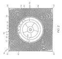
FIG. 2 is a plan view of an embodiment of a heat sink; and -
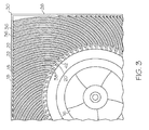
FIG. 3 is a plan view of another embodiment of a heat sink. - The detailed description explains embodiments of the invention, together with advantages and features, by way of example with reference to the drawings.
- Shown in
FIG. 1 is a schematic view of anelectronics package 10 including anenclosure 50 containing one or more heat-producingelectronics components 12, for example, a power converter or the like. Aheat sink 14 is located proximate to thecomponent 12, and in some embodiments, adjacent to, or in contact with thecomponent 12. - Referring now to
FIG. 2 , theheat sink 14 is configured as aradial heat sink 14. Theheat sink 14 includes a fan orblower 16, which, in some embodiments, is substantially integral to theheat sink 14, and in some embodiments, is a centrifugal blower located substantially at a center of theheat sink 14. A plurality offins 18 are arranged on aheat sink plate 40 and extend outwardly from aperiphery 20 of theblower 16 toward aperimeter 26 of theheat sink 14 defining a plurality ofheat sink channels 22 betweenadjacent fins 18 of the plurality of fins. In operation, thermal energy is transferred from thecomponent 12 to theheat sink 14 and into the plurality offins 18. Theblower 16, connected to a power source (not shown), is activated and a total head, including a dynamic head component and an associated flow velocity, is created andairflow 24 is urged from theblower 16 into the plurality ofchannels 22. Theblower 16 provides airflow of a substantially equal in velocity to eachchannel 22 of the plurality ofchannels 22 at achannel inlet 42. As theairflow 24 flows through the plurality ofchannels 22 and past thefins 18, thermal energy is transferred to theairflow 24 and ejected when theairflow 24 reaches theperimeter 26 of theheat sink 14. - As can be seen in
FIG. 2 , adistance 28 from theperiphery 20 of the blower 1G to theperimeter 26 of theheat sink 14 varies around theperiphery 20 of theblower 16. Thus, a length of the plurality ofchannels 22 varies around theperimeter 26 of theheat sink 14. For example, thedistance 28 is greater at acorner 30 of theheat sink 14 than at amidpoint 32 of aside 34 of theheat sink 14. When theairflow 24 flows throughchannels 22 of uniform configuration, such as width, but of differing lengths, a different pressure drop is seen atchannel exits 36 ofchannels 22 having differing lengths. To increase efficiency of theheat sink 14 and to reduce losses, an average velocity of theair flow 24 at thechannel entrances 42 is substantially equal for eachchannel 22 of the plurality ofchannels 22, and the total pressure drop from eachchannel inlet 42 to eachchannel exit 36 is also substantially equal for eachchannel 22 of the plurality ofchannels 22. - As shown in
FIG. 3 , total pressure drop matching is accomplished by introducing variations in thechannel 22 geometry around theheat sink 14. For example,shorter channels 22 may be narrower, withadjacent fins 18 closer together, whilelonger channels 22 may be wider, withadjacent fins 18 further apart, thus equalizing the total pressure drop at eachchannel 22.Channel 22 width may also be varied to cool a non-uniform heat flux fromcomponents 12 in contact with theheat sink 14. A greater number ofnarrow channels 22 may be utilized to cool a relatively highheat flux component 12, while a lesser number ofwider channels 22 may be utilized to cool a relatively lowheat flux component 12. Further,longer channels 22 may also have afin tip 38 retracted from theblower 16, relative tofin tips 38 ofother channels 22, thus retracting thechannel inlet 42 from theblower 16 relative toother channel inlets 42. While varying thechannel 22 width and staggering thefin tip 38 position are illustrated as means to equalize the total pressure drop, any suitable means may be utilized to achieve the pressure drop equalization. For example, pins may be inserted intolonger channels 22, or a thickness offins 18 may be varied to achieve the total pressure drop equalization. - While the invention has been described in detail in connection with only a limited number of embodiments, it should be readily understood that the invention is not limited to such disclosed embodiments. Rather, the invention can be modified to incorporate any number of variations, alterations, substitutions or equivalent arrangements not heretofore described, but which are commensurate with the spirit and scope of the invention. Additionally, while various embodiments of the invention have been described, it is to be understood that aspects of the invention may include only some of the described embodiments. Accordingly, the invention is not to be seen as limited by the foregoing description, but is only limited by the scope of the appended claims.
Claims (10)
- A heat sink (14) comprising:a blower (16) disposed in the heat sink (14); anda plurality of fins (18) extending from a periphery (20) of the blower (16) toward a perimeter (26) of the heat sink (14), the plurality of fins (18) defining a plurality of channels (22) each having a channel inlet (42) disposed at the blower (16) and a channel exit (36) disposed at the perimeter (26) of the heat sink (14), the plurality of channels (22) varying in length around the perimeter (26) of the heat sink (14);wherein a velocity of an air flow from the blower (16) at each channel inlet (42) is substantially equal for each channel (22) of the plurality of channels (22), and a total pressure drop from the channel inlet (42) to the channel exit (36) is substantially equal for each channel (22) of the plurality of channels (22).
- The heat sink of Claim 1, wherein a width of the plurality of channels (22) is varied to equalize the total pressure drop.
- The heat sink of Claim 2, wherein the plurality of channels (22) vary in width to cool a non-uniform heat flux.
- The heat sink of Claim 2 or 3, wherein the width of the plurality of channels (22) is varied by varying a distance between adjacent fins.
- The heat sink of Claim 2, 3 or 4, wherein the width of the plurality of channels (22) is varied by varying a fin thickness of the plurality of fins (18).
- The heat sink of any preceding Claim, wherein a position of a channel inlet (42) relative to the blower (16) is varied to equalize the total pressure drop.
- The heat sink of any preceding Claim, wherein the blower (16) is a centrifugal blower.
- The heat sink of any preceding Claim, wherein the plurality of channels (22) are arranged on a non-circular plan-form.
- An electronics package (10) comprising:an enclosure (50);one or more electronics components (12) disposed in the enclosure (50); anda heat sink (14) disposed in proximity to the one or more electronics components (12) to cool the one or more electronics components (12), the heat sink (14) being a heat sink of any preceding Claim.
- A method of dissipating thermal energy from an electronics component (12) comprising:locating a heat sink (14) proximate to the electronics component (12), the heat sink (14) including:a blower (16) disposed in the heat sink (14); anda plurality of fins (18) extending from a periphery (20) of the blower (16) toward a perimeter (26) of the heat sink (14), the plurality of fins (18) defining a plurality of channels (22) each having a channel inlet (42) disposed at the blower (16) and a channel exit (36) disposed at the perimeter (26) of the heat sink (14), the plurality of channels (22) varying in length around the perimeter (26) of the heat sink (14),transferring thermal energy from the electronics component (12) to the plurality of fins (18);urging an airflow from the blower (16) into the plurality of channels (22) at the channel inlets (42);flowing the airflow past the plurality of fins (18), thereby transferring thermal energy from the plurality of fins (18) to the airflow; andflowing the airflow to a plurality of channel exits (36) thereby dissipating the thermal energy;wherein a velocity of the air flow at the channel inlet (42) is substantially equal for each channel (22) of the plurality of channels (22), and a total pressure drop from the channel inlet (42) to channel exit (36) is substantially equal for each channel (22) of the plurality of channels (22).
Applications Claiming Priority (1)
| Application Number | Priority Date | Filing Date | Title |
|---|---|---|---|
| US12/838,536 US8295046B2 (en) | 2010-07-19 | 2010-07-19 | Non-circular radial heat sink |
Publications (3)
| Publication Number | Publication Date |
|---|---|
| EP2410564A2 true EP2410564A2 (en) | 2012-01-25 |
| EP2410564A3 EP2410564A3 (en) | 2013-10-23 |
| EP2410564B1 EP2410564B1 (en) | 2015-10-28 |
Family
ID=44653130
Family Applications (1)
| Application Number | Title | Priority Date | Filing Date |
|---|---|---|---|
| EP11173330.9A Active EP2410564B1 (en) | 2010-07-19 | 2011-07-08 | Non-circular radial heat sink |
Country Status (2)
| Country | Link |
|---|---|
| US (1) | US8295046B2 (en) |
| EP (1) | EP2410564B1 (en) |
Cited By (1)
| Publication number | Priority date | Publication date | Assignee | Title |
|---|---|---|---|---|
| EP3734655A1 (en) * | 2019-04-30 | 2020-11-04 | Hamilton Sundstrand Corporation | High efficiency integrated ax-radial blower and heat exchanger |
Families Citing this family (17)
| Publication number | Priority date | Publication date | Assignee | Title |
|---|---|---|---|---|
| US10852069B2 (en) | 2010-05-04 | 2020-12-01 | Fractal Heatsink Technologies, LLC | System and method for maintaining efficiency of a fractal heat sink |
| US10041745B2 (en) | 2010-05-04 | 2018-08-07 | Fractal Heatsink Technologies LLC | Fractal heat transfer device |
| US9228785B2 (en) | 2010-05-04 | 2016-01-05 | Alexander Poltorak | Fractal heat transfer device |
| US8964388B2 (en) | 2012-09-30 | 2015-02-24 | Hamilton Sundstrand Corporation | Integrated blower diffuser and heat exchanger for electronics enclosure |
| US9095075B2 (en) | 2012-11-27 | 2015-07-28 | Hamilton Sundstrand Corporation | Enclosure for electronic components with enhanced cooling |
| AT515828B1 (en) * | 2014-05-23 | 2022-02-15 | Fronius Int Gmbh | Cooling device and inverter housing with such a cooling device |
| GB2528161B (en) * | 2014-07-09 | 2020-04-29 | Hamilton Sundstrand Corp | Integrated blower diffuser-fin single phase heat exchanger |
| US9746888B2 (en) * | 2014-09-12 | 2017-08-29 | Microsoft Technology Licensing, Llc | Uniform flow heat sink |
| US10830545B2 (en) | 2016-07-12 | 2020-11-10 | Fractal Heatsink Technologies, LLC | System and method for maintaining efficiency of a heat sink |
| WO2019018446A1 (en) * | 2017-07-17 | 2019-01-24 | Fractal Heatsink Technologies, LLC | Multi-fractal heat sink system and method |
| JP7081203B2 (en) * | 2018-02-26 | 2022-06-07 | トヨタ自動車株式会社 | Radiation fin structure and cooling structure of electronic board using this |
| US11290622B2 (en) * | 2019-01-28 | 2022-03-29 | Magna Electronics Inc. | Vehicular forward camera module with integrated cooling fan |
| US11997371B2 (en) | 2021-01-22 | 2024-05-28 | Magna Electronics Inc. | Vehicular cooling system for forward camera module |
| EP4068930B1 (en) | 2021-04-01 | 2024-03-13 | Ovh | A rack system for housing an electronic device |
| CA3152605A1 (en) | 2021-04-01 | 2022-10-01 | Ovh | Systems and methods for autonomously activable redundant cooling of a heat generating component |
| EP4316219A1 (en) | 2021-04-01 | 2024-02-07 | Ovh | Scissor structure for cable/tube management of rack-mounted liquid-cooled electronic assemblies |
| EP4068927B1 (en) | 2021-04-01 | 2024-07-03 | Ovh | Immersion cooling system with dual dielectric cooling liquid circulation |
Family Cites Families (41)
| Publication number | Priority date | Publication date | Assignee | Title |
|---|---|---|---|---|
| US4733293A (en) * | 1987-02-13 | 1988-03-22 | Unisys Corporation | Heat sink device assembly for encumbered IC package |
| US5597034A (en) * | 1994-07-01 | 1997-01-28 | Digital Equipment Corporation | High performance fan heatsink assembly |
| US5661638A (en) * | 1995-11-03 | 1997-08-26 | Silicon Graphics, Inc. | High performance spiral heat sink |
| JP3352362B2 (en) * | 1997-07-14 | 2002-12-03 | 三菱電機株式会社 | Heat sink |
| US6167952B1 (en) | 1998-03-03 | 2001-01-02 | Hamilton Sundstrand Corporation | Cooling apparatus and method of assembling same |
| US6213195B1 (en) | 1998-12-23 | 2001-04-10 | Hamilton Sundstrand Corporation | Modular coolant manifold for use with power electronics devices having integrated coolers |
| US6244331B1 (en) | 1999-10-22 | 2001-06-12 | Intel Corporation | Heatsink with integrated blower for improved heat transfer |
| US6278353B1 (en) | 1999-11-16 | 2001-08-21 | Hamilton Sundstrand Corporation | Planar magnetics with integrated cooling |
| TWI222344B (en) * | 1999-12-09 | 2004-10-11 | Advanced Rotary Systems Llc | Cooler for electronic devices |
| US6659169B1 (en) * | 1999-12-09 | 2003-12-09 | Advanced Rotary Systems, Llc | Cooler for electronic devices |
| TW590268U (en) | 2000-08-08 | 2004-06-01 | Wistron Corp | Heat dissipating device |
| US6633484B1 (en) | 2000-11-20 | 2003-10-14 | Intel Corporation | Heat-dissipating devices, systems, and methods with small footprint |
| US6404634B1 (en) * | 2000-12-06 | 2002-06-11 | Hewlett-Packard Company | Single piece heat sink for computer chip |
| TW532738U (en) * | 2001-03-27 | 2003-05-11 | Foxconn Prec Components Co Ltd | Heat sink assembly |
| JP3686005B2 (en) * | 2001-03-30 | 2005-08-24 | 山洋電気株式会社 | Cooling device with heat sink |
| US6446707B1 (en) | 2001-04-17 | 2002-09-10 | Hewlett-Packard Company | Active heat sink structure with directed air flow |
| US6778390B2 (en) | 2001-05-15 | 2004-08-17 | Nvidia Corporation | High-performance heat sink for printed circuit boards |
| US6479895B1 (en) | 2001-05-18 | 2002-11-12 | Intel Corporation | High performance air cooled heat sinks used in high density packaging applications |
| US20030007867A1 (en) | 2001-07-05 | 2003-01-09 | Enlight Corporation | CPU cooling structure with a ventilation hood |
| US6505680B1 (en) | 2001-07-27 | 2003-01-14 | Hewlett-Packard Company | High performance cooling device |
| US6664673B2 (en) | 2001-08-27 | 2003-12-16 | Advanced Rotary Systems Llc | Cooler for electronic devices |
| US6671172B2 (en) * | 2001-09-10 | 2003-12-30 | Intel Corporation | Electronic assemblies with high capacity curved fin heat sinks |
| US6705144B2 (en) | 2001-09-10 | 2004-03-16 | Intel Corporation | Manufacturing process for a radial fin heat sink |
| US6657862B2 (en) * | 2001-09-10 | 2003-12-02 | Intel Corporation | Radial folded fin heat sinks and methods of making and using same |
| US6543522B1 (en) | 2001-10-31 | 2003-04-08 | Hewlett-Packard Development Company, L.P. | Arrayed fin cooler |
| AUPR982502A0 (en) | 2002-01-03 | 2002-01-31 | Pax Fluid Systems Inc. | A heat exchanger |
| US6935419B2 (en) * | 2002-02-20 | 2005-08-30 | Hewlett-Packard Development Company, L.P. | Heat sink apparatus with air duct |
| US6587341B1 (en) | 2002-03-04 | 2003-07-01 | Chun Long Metal Co., Ltd. | Heat dissipater structure |
| US6714415B1 (en) | 2003-03-13 | 2004-03-30 | Intel Corporation | Split fin heat sink |
| US6937473B2 (en) * | 2003-06-30 | 2005-08-30 | Intel Corporation | Heatsink device and method |
| TWM244719U (en) | 2003-08-27 | 2004-09-21 | Hon Hai Prec Ind Co Ltd | Heat sink |
| US7361081B2 (en) | 2004-07-23 | 2008-04-22 | Hewlett-Packard Development Company, L.P. | Small form factor air jet cooling system |
| US8020608B2 (en) | 2004-08-31 | 2011-09-20 | Hewlett-Packard Development Company, L.P. | Heat sink fin with stator blade |
| US7164584B2 (en) | 2004-10-19 | 2007-01-16 | Honeywell International Inc. | Modular heatsink, electromagnetic device incorporating a modular heatsink and method of cooling an electromagnetic device using a modular heatsink |
| KR100696494B1 (en) | 2005-02-22 | 2007-03-19 | 삼성에스디아이 주식회사 | Heat dissipation structure of driving circuit chip and display device having same |
| US7334422B2 (en) | 2005-11-29 | 2008-02-26 | Hamilton Sundstrand Corporation | Cabin air conditioning system with liquid cooling for power electronics |
| US7880283B2 (en) | 2006-04-25 | 2011-02-01 | International Rectifier Corporation | High reliability power module |
| US7760506B1 (en) | 2007-06-06 | 2010-07-20 | Hewlett-Packard Development Company, L.P. | Electronic components, systems and apparatus with air flow devices |
| US7775062B2 (en) | 2008-09-15 | 2010-08-17 | Mike Blomquist | Modular cooling system |
| US7796389B2 (en) | 2008-11-26 | 2010-09-14 | General Electric Company | Method and apparatus for cooling electronics |
| US20100170657A1 (en) | 2009-01-06 | 2010-07-08 | United Technologies Corporation | Integrated blower diffuser-fin heat sink |
-
2010
- 2010-07-19 US US12/838,536 patent/US8295046B2/en active Active
-
2011
- 2011-07-08 EP EP11173330.9A patent/EP2410564B1/en active Active
Non-Patent Citations (1)
| Title |
|---|
| None |
Cited By (1)
| Publication number | Priority date | Publication date | Assignee | Title |
|---|---|---|---|---|
| EP3734655A1 (en) * | 2019-04-30 | 2020-11-04 | Hamilton Sundstrand Corporation | High efficiency integrated ax-radial blower and heat exchanger |
Also Published As
| Publication number | Publication date |
|---|---|
| US20120014064A1 (en) | 2012-01-19 |
| EP2410564B1 (en) | 2015-10-28 |
| EP2410564A3 (en) | 2013-10-23 |
| US8295046B2 (en) | 2012-10-23 |
Similar Documents
| Publication | Publication Date | Title |
|---|---|---|
| EP2410564B1 (en) | Non-circular radial heat sink | |
| EP2427037A2 (en) | Electronics package with radial heat sink and integrated blower | |
| US20100170657A1 (en) | Integrated blower diffuser-fin heat sink | |
| US8453715B2 (en) | Synthetic jet embedded heat sink | |
| US5335143A (en) | Disk augmented heat transfer system | |
| US8376031B2 (en) | Blowerless heat exchanger based on micro-jet entrainment | |
| US6698505B2 (en) | Cooler for an electronic device | |
| US20090168344A1 (en) | Thermal device with electrokinetic air flow | |
| CN104242549B (en) | Use the cooling of the motor of radially installed fan | |
| JP2008140802A (en) | heatsink | |
| US9360019B2 (en) | Fan | |
| CN101832276B (en) | Fan and its guide structure | |
| US12604440B2 (en) | Lower module of power electronic device | |
| US8308451B2 (en) | Injection molded fan motor controller housing with advanced cooling features | |
| US9826661B2 (en) | Heat module | |
| US9409264B2 (en) | Interleaved heat sink and fan assembly | |
| US10986750B2 (en) | Heat exchange device in directed flow system | |
| JP2012164887A (en) | Radiator and heat dissipation system | |
| JP2009004523A (en) | Cooling device and heat sink | |
| CN100531539C (en) | Heat radiating device | |
| TWI815016B (en) | Heat dissipation module and electronic device | |
| Yang et al. | An in-situ performance test of liquid cooling for a server computer system | |
| CN101205934A (en) | Fan and fan frame thereof | |
| Yang et al. | Development of a mini liquid cooling system for high heat flux electronic devices | |
| TW200743945A (en) | Heat dissipation apparatus |
Legal Events
| Date | Code | Title | Description |
|---|---|---|---|
| AK | Designated contracting states |
Kind code of ref document: A2 Designated state(s): AL AT BE BG CH CY CZ DE DK EE ES FI FR GB GR HR HU IE IS IT LI LT LU LV MC MK MT NL NO PL PT RO RS SE SI SK SM TR |
|
| AX | Request for extension of the european patent |
Extension state: BA ME |
|
| PUAI | Public reference made under article 153(3) epc to a published international application that has entered the european phase |
Free format text: ORIGINAL CODE: 0009012 |
|
| PUAL | Search report despatched |
Free format text: ORIGINAL CODE: 0009013 |
|
| AK | Designated contracting states |
Kind code of ref document: A3 Designated state(s): AL AT BE BG CH CY CZ DE DK EE ES FI FR GB GR HR HU IE IS IT LI LT LU LV MC MK MT NL NO PL PT RO RS SE SI SK SM TR |
|
| AX | Request for extension of the european patent |
Extension state: BA ME |
|
| RIC1 | Information provided on ipc code assigned before grant |
Ipc: H01L 23/467 20060101AFI20130919BHEP |
|
| 17P | Request for examination filed |
Effective date: 20140422 |
|
| RBV | Designated contracting states (corrected) |
Designated state(s): AL AT BE BG CH CY CZ DE DK EE ES FI FR GB GR HR HU IE IS IT LI LT LU LV MC MK MT NL NO PL PT RO RS SE SI SK SM TR |
|
| GRAP | Despatch of communication of intention to grant a patent |
Free format text: ORIGINAL CODE: EPIDOSNIGR1 |
|
| INTG | Intention to grant announced |
Effective date: 20150529 |
|
| GRAS | Grant fee paid |
Free format text: ORIGINAL CODE: EPIDOSNIGR3 |
|
| GRAA | (expected) grant |
Free format text: ORIGINAL CODE: 0009210 |
|
| AK | Designated contracting states |
Kind code of ref document: B1 Designated state(s): AL AT BE BG CH CY CZ DE DK EE ES FI FR GB GR HR HU IE IS IT LI LT LU LV MC MK MT NL NO PL PT RO RS SE SI SK SM TR |
|
| REG | Reference to a national code |
Ref country code: GB Ref legal event code: FG4D |
|
| REG | Reference to a national code |
Ref country code: CH Ref legal event code: EP |
|
| REG | Reference to a national code |
Ref country code: AT Ref legal event code: REF Ref document number: 758353 Country of ref document: AT Kind code of ref document: T Effective date: 20151115 |
|
| REG | Reference to a national code |
Ref country code: IE Ref legal event code: FG4D |
|
| REG | Reference to a national code |
Ref country code: DE Ref legal event code: R096 Ref document number: 602011020951 Country of ref document: DE |
|
| REG | Reference to a national code |
Ref country code: LT Ref legal event code: MG4D |
|
| REG | Reference to a national code |
Ref country code: NL Ref legal event code: MP Effective date: 20151028 |
|
| REG | Reference to a national code |
Ref country code: AT Ref legal event code: MK05 Ref document number: 758353 Country of ref document: AT Kind code of ref document: T Effective date: 20151028 |
|
| PG25 | Lapsed in a contracting state [announced via postgrant information from national office to epo] |
Ref country code: ES Free format text: LAPSE BECAUSE OF FAILURE TO SUBMIT A TRANSLATION OF THE DESCRIPTION OR TO PAY THE FEE WITHIN THE PRESCRIBED TIME-LIMIT Effective date: 20151028 Ref country code: NO Free format text: LAPSE BECAUSE OF FAILURE TO SUBMIT A TRANSLATION OF THE DESCRIPTION OR TO PAY THE FEE WITHIN THE PRESCRIBED TIME-LIMIT Effective date: 20160128 Ref country code: IS Free format text: LAPSE BECAUSE OF FAILURE TO SUBMIT A TRANSLATION OF THE DESCRIPTION OR TO PAY THE FEE WITHIN THE PRESCRIBED TIME-LIMIT Effective date: 20160228 Ref country code: IT Free format text: LAPSE BECAUSE OF FAILURE TO SUBMIT A TRANSLATION OF THE DESCRIPTION OR TO PAY THE FEE WITHIN THE PRESCRIBED TIME-LIMIT Effective date: 20151028 Ref country code: LT Free format text: LAPSE BECAUSE OF FAILURE TO SUBMIT A TRANSLATION OF THE DESCRIPTION OR TO PAY THE FEE WITHIN THE PRESCRIBED TIME-LIMIT Effective date: 20151028 Ref country code: NL Free format text: LAPSE BECAUSE OF FAILURE TO SUBMIT A TRANSLATION OF THE DESCRIPTION OR TO PAY THE FEE WITHIN THE PRESCRIBED TIME-LIMIT Effective date: 20151028 Ref country code: HR Free format text: LAPSE BECAUSE OF FAILURE TO SUBMIT A TRANSLATION OF THE DESCRIPTION OR TO PAY THE FEE WITHIN THE PRESCRIBED TIME-LIMIT Effective date: 20151028 |
|
| PG25 | Lapsed in a contracting state [announced via postgrant information from national office to epo] |
Ref country code: FI Free format text: LAPSE BECAUSE OF FAILURE TO SUBMIT A TRANSLATION OF THE DESCRIPTION OR TO PAY THE FEE WITHIN THE PRESCRIBED TIME-LIMIT Effective date: 20151028 Ref country code: PT Free format text: LAPSE BECAUSE OF FAILURE TO SUBMIT A TRANSLATION OF THE DESCRIPTION OR TO PAY THE FEE WITHIN THE PRESCRIBED TIME-LIMIT Effective date: 20160229 Ref country code: SE Free format text: LAPSE BECAUSE OF FAILURE TO SUBMIT A TRANSLATION OF THE DESCRIPTION OR TO PAY THE FEE WITHIN THE PRESCRIBED TIME-LIMIT Effective date: 20151028 Ref country code: GR Free format text: LAPSE BECAUSE OF FAILURE TO SUBMIT A TRANSLATION OF THE DESCRIPTION OR TO PAY THE FEE WITHIN THE PRESCRIBED TIME-LIMIT Effective date: 20160129 Ref country code: PL Free format text: LAPSE BECAUSE OF FAILURE TO SUBMIT A TRANSLATION OF THE DESCRIPTION OR TO PAY THE FEE WITHIN THE PRESCRIBED TIME-LIMIT Effective date: 20151028 Ref country code: LV Free format text: LAPSE BECAUSE OF FAILURE TO SUBMIT A TRANSLATION OF THE DESCRIPTION OR TO PAY THE FEE WITHIN THE PRESCRIBED TIME-LIMIT Effective date: 20151028 Ref country code: RS Free format text: LAPSE BECAUSE OF FAILURE TO SUBMIT A TRANSLATION OF THE DESCRIPTION OR TO PAY THE FEE WITHIN THE PRESCRIBED TIME-LIMIT Effective date: 20151028 Ref country code: AT Free format text: LAPSE BECAUSE OF FAILURE TO SUBMIT A TRANSLATION OF THE DESCRIPTION OR TO PAY THE FEE WITHIN THE PRESCRIBED TIME-LIMIT Effective date: 20151028 |
|
| REG | Reference to a national code |
Ref country code: FR Ref legal event code: PLFP Year of fee payment: 6 |
|
| PG25 | Lapsed in a contracting state [announced via postgrant information from national office to epo] |
Ref country code: CZ Free format text: LAPSE BECAUSE OF FAILURE TO SUBMIT A TRANSLATION OF THE DESCRIPTION OR TO PAY THE FEE WITHIN THE PRESCRIBED TIME-LIMIT Effective date: 20151028 |
|
| REG | Reference to a national code |
Ref country code: DE Ref legal event code: R097 Ref document number: 602011020951 Country of ref document: DE |
|
| PG25 | Lapsed in a contracting state [announced via postgrant information from national office to epo] |
Ref country code: SM Free format text: LAPSE BECAUSE OF FAILURE TO SUBMIT A TRANSLATION OF THE DESCRIPTION OR TO PAY THE FEE WITHIN THE PRESCRIBED TIME-LIMIT Effective date: 20151028 Ref country code: RO Free format text: LAPSE BECAUSE OF FAILURE TO SUBMIT A TRANSLATION OF THE DESCRIPTION OR TO PAY THE FEE WITHIN THE PRESCRIBED TIME-LIMIT Effective date: 20151028 Ref country code: SK Free format text: LAPSE BECAUSE OF FAILURE TO SUBMIT A TRANSLATION OF THE DESCRIPTION OR TO PAY THE FEE WITHIN THE PRESCRIBED TIME-LIMIT Effective date: 20151028 Ref country code: EE Free format text: LAPSE BECAUSE OF FAILURE TO SUBMIT A TRANSLATION OF THE DESCRIPTION OR TO PAY THE FEE WITHIN THE PRESCRIBED TIME-LIMIT Effective date: 20151028 Ref country code: DK Free format text: LAPSE BECAUSE OF FAILURE TO SUBMIT A TRANSLATION OF THE DESCRIPTION OR TO PAY THE FEE WITHIN THE PRESCRIBED TIME-LIMIT Effective date: 20151028 |
|
| PLBE | No opposition filed within time limit |
Free format text: ORIGINAL CODE: 0009261 |
|
| STAA | Information on the status of an ep patent application or granted ep patent |
Free format text: STATUS: NO OPPOSITION FILED WITHIN TIME LIMIT |
|
| 26N | No opposition filed |
Effective date: 20160729 |
|
| PG25 | Lapsed in a contracting state [announced via postgrant information from national office to epo] |
Ref country code: SI Free format text: LAPSE BECAUSE OF FAILURE TO SUBMIT A TRANSLATION OF THE DESCRIPTION OR TO PAY THE FEE WITHIN THE PRESCRIBED TIME-LIMIT Effective date: 20151028 |
|
| PG25 | Lapsed in a contracting state [announced via postgrant information from national office to epo] |
Ref country code: BE Free format text: LAPSE BECAUSE OF FAILURE TO SUBMIT A TRANSLATION OF THE DESCRIPTION OR TO PAY THE FEE WITHIN THE PRESCRIBED TIME-LIMIT Effective date: 20151028 |
|
| REG | Reference to a national code |
Ref country code: CH Ref legal event code: PL |
|
| PG25 | Lapsed in a contracting state [announced via postgrant information from national office to epo] |
Ref country code: MC Free format text: LAPSE BECAUSE OF FAILURE TO SUBMIT A TRANSLATION OF THE DESCRIPTION OR TO PAY THE FEE WITHIN THE PRESCRIBED TIME-LIMIT Effective date: 20151028 |
|
| PG25 | Lapsed in a contracting state [announced via postgrant information from national office to epo] |
Ref country code: CH Free format text: LAPSE BECAUSE OF NON-PAYMENT OF DUE FEES Effective date: 20160731 Ref country code: LI Free format text: LAPSE BECAUSE OF NON-PAYMENT OF DUE FEES Effective date: 20160731 |
|
| REG | Reference to a national code |
Ref country code: IE Ref legal event code: MM4A |
|
| REG | Reference to a national code |
Ref country code: FR Ref legal event code: PLFP Year of fee payment: 7 |
|
| PG25 | Lapsed in a contracting state [announced via postgrant information from national office to epo] |
Ref country code: IE Free format text: LAPSE BECAUSE OF NON-PAYMENT OF DUE FEES Effective date: 20160708 |
|
| PG25 | Lapsed in a contracting state [announced via postgrant information from national office to epo] |
Ref country code: LU Free format text: LAPSE BECAUSE OF NON-PAYMENT OF DUE FEES Effective date: 20160708 |
|
| PG25 | Lapsed in a contracting state [announced via postgrant information from national office to epo] |
Ref country code: CY Free format text: LAPSE BECAUSE OF FAILURE TO SUBMIT A TRANSLATION OF THE DESCRIPTION OR TO PAY THE FEE WITHIN THE PRESCRIBED TIME-LIMIT Effective date: 20151028 Ref country code: HU Free format text: LAPSE BECAUSE OF FAILURE TO SUBMIT A TRANSLATION OF THE DESCRIPTION OR TO PAY THE FEE WITHIN THE PRESCRIBED TIME-LIMIT; INVALID AB INITIO Effective date: 20110708 |
|
| REG | Reference to a national code |
Ref country code: FR Ref legal event code: PLFP Year of fee payment: 8 |
|
| PG25 | Lapsed in a contracting state [announced via postgrant information from national office to epo] |
Ref country code: MK Free format text: LAPSE BECAUSE OF FAILURE TO SUBMIT A TRANSLATION OF THE DESCRIPTION OR TO PAY THE FEE WITHIN THE PRESCRIBED TIME-LIMIT Effective date: 20151028 Ref country code: TR Free format text: LAPSE BECAUSE OF FAILURE TO SUBMIT A TRANSLATION OF THE DESCRIPTION OR TO PAY THE FEE WITHIN THE PRESCRIBED TIME-LIMIT Effective date: 20151028 Ref country code: MT Free format text: LAPSE BECAUSE OF NON-PAYMENT OF DUE FEES Effective date: 20160731 |
|
| PG25 | Lapsed in a contracting state [announced via postgrant information from national office to epo] |
Ref country code: BG Free format text: LAPSE BECAUSE OF FAILURE TO SUBMIT A TRANSLATION OF THE DESCRIPTION OR TO PAY THE FEE WITHIN THE PRESCRIBED TIME-LIMIT Effective date: 20151028 |
|
| PG25 | Lapsed in a contracting state [announced via postgrant information from national office to epo] |
Ref country code: AL Free format text: LAPSE BECAUSE OF FAILURE TO SUBMIT A TRANSLATION OF THE DESCRIPTION OR TO PAY THE FEE WITHIN THE PRESCRIBED TIME-LIMIT Effective date: 20151028 |
|
| REG | Reference to a national code |
Ref country code: DE Ref legal event code: R082 Ref document number: 602011020951 Country of ref document: DE |
|
| P01 | Opt-out of the competence of the unified patent court (upc) registered |
Effective date: 20230522 |
|
| PGFP | Annual fee paid to national office [announced via postgrant information from national office to epo] |
Ref country code: GB Payment date: 20250619 Year of fee payment: 15 |
|
| PGFP | Annual fee paid to national office [announced via postgrant information from national office to epo] |
Ref country code: FR Payment date: 20250619 Year of fee payment: 15 |
|
| PGFP | Annual fee paid to national office [announced via postgrant information from national office to epo] |
Ref country code: DE Payment date: 20250620 Year of fee payment: 15 |
|
| REG | Reference to a national code |
Ref country code: DE Ref legal event code: R079 Ref document number: 602011020951 Country of ref document: DE Free format text: PREVIOUS MAIN CLASS: H01L0023467000 Ipc: H10W0040430000 |