EP2410301A2 - Systems and methods for liquid level sensing having a differentiating output - Google Patents
Systems and methods for liquid level sensing having a differentiating output Download PDFInfo
- Publication number
- EP2410301A2 EP2410301A2 EP11250652A EP11250652A EP2410301A2 EP 2410301 A2 EP2410301 A2 EP 2410301A2 EP 11250652 A EP11250652 A EP 11250652A EP 11250652 A EP11250652 A EP 11250652A EP 2410301 A2 EP2410301 A2 EP 2410301A2
- Authority
- EP
- European Patent Office
- Prior art keywords
- temperature sensor
- sensing
- tank
- liquid
- temperature
- Prior art date
- Legal status (The legal status is an assumption and is not a legal conclusion. Google has not performed a legal analysis and makes no representation as to the accuracy of the status listed.)
- Granted
Links
Images





Classifications
-
- G—PHYSICS
- G01—MEASURING; TESTING
- G01F—MEASURING VOLUME, VOLUME FLOW, MASS FLOW OR LIQUID LEVEL; METERING BY VOLUME
- G01F23/00—Indicating or measuring liquid level or level of fluent solid material, e.g. indicating in terms of volume or indicating by means of an alarm
- G01F23/22—Indicating or measuring liquid level or level of fluent solid material, e.g. indicating in terms of volume or indicating by means of an alarm by measuring physical variables, other than linear dimensions, pressure or weight, dependent on the level to be measured, e.g. by difference of heat transfer of steam or water
- G01F23/24—Indicating or measuring liquid level or level of fluent solid material, e.g. indicating in terms of volume or indicating by means of an alarm by measuring physical variables, other than linear dimensions, pressure or weight, dependent on the level to be measured, e.g. by difference of heat transfer of steam or water by measuring variations of resistance of resistors due to contact with conductor fluid
- G01F23/241—Indicating or measuring liquid level or level of fluent solid material, e.g. indicating in terms of volume or indicating by means of an alarm by measuring physical variables, other than linear dimensions, pressure or weight, dependent on the level to be measured, e.g. by difference of heat transfer of steam or water by measuring variations of resistance of resistors due to contact with conductor fluid for discrete levels
- G01F23/242—Mounting arrangements for electrodes
-
- G—PHYSICS
- G01—MEASURING; TESTING
- G01F—MEASURING VOLUME, VOLUME FLOW, MASS FLOW OR LIQUID LEVEL; METERING BY VOLUME
- G01F23/00—Indicating or measuring liquid level or level of fluent solid material, e.g. indicating in terms of volume or indicating by means of an alarm
- G01F23/22—Indicating or measuring liquid level or level of fluent solid material, e.g. indicating in terms of volume or indicating by means of an alarm by measuring physical variables, other than linear dimensions, pressure or weight, dependent on the level to be measured, e.g. by difference of heat transfer of steam or water
- G01F23/24—Indicating or measuring liquid level or level of fluent solid material, e.g. indicating in terms of volume or indicating by means of an alarm by measuring physical variables, other than linear dimensions, pressure or weight, dependent on the level to be measured, e.g. by difference of heat transfer of steam or water by measuring variations of resistance of resistors due to contact with conductor fluid
- G01F23/241—Indicating or measuring liquid level or level of fluent solid material, e.g. indicating in terms of volume or indicating by means of an alarm by measuring physical variables, other than linear dimensions, pressure or weight, dependent on the level to be measured, e.g. by difference of heat transfer of steam or water by measuring variations of resistance of resistors due to contact with conductor fluid for discrete levels
- G01F23/243—Schematic arrangements of probes combined with measuring circuits
-
- G—PHYSICS
- G01—MEASURING; TESTING
- G01F—MEASURING VOLUME, VOLUME FLOW, MASS FLOW OR LIQUID LEVEL; METERING BY VOLUME
- G01F23/00—Indicating or measuring liquid level or level of fluent solid material, e.g. indicating in terms of volume or indicating by means of an alarm
- G01F23/22—Indicating or measuring liquid level or level of fluent solid material, e.g. indicating in terms of volume or indicating by means of an alarm by measuring physical variables, other than linear dimensions, pressure or weight, dependent on the level to be measured, e.g. by difference of heat transfer of steam or water
- G01F23/24—Indicating or measuring liquid level or level of fluent solid material, e.g. indicating in terms of volume or indicating by means of an alarm by measuring physical variables, other than linear dimensions, pressure or weight, dependent on the level to be measured, e.g. by difference of heat transfer of steam or water by measuring variations of resistance of resistors due to contact with conductor fluid
- G01F23/246—Indicating or measuring liquid level or level of fluent solid material, e.g. indicating in terms of volume or indicating by means of an alarm by measuring physical variables, other than linear dimensions, pressure or weight, dependent on the level to be measured, e.g. by difference of heat transfer of steam or water by measuring variations of resistance of resistors due to contact with conductor fluid thermal devices
- G01F23/247—Indicating or measuring liquid level or level of fluent solid material, e.g. indicating in terms of volume or indicating by means of an alarm by measuring physical variables, other than linear dimensions, pressure or weight, dependent on the level to be measured, e.g. by difference of heat transfer of steam or water by measuring variations of resistance of resistors due to contact with conductor fluid thermal devices for discrete levels
-
- G—PHYSICS
- G01—MEASURING; TESTING
- G01F—MEASURING VOLUME, VOLUME FLOW, MASS FLOW OR LIQUID LEVEL; METERING BY VOLUME
- G01F23/00—Indicating or measuring liquid level or level of fluent solid material, e.g. indicating in terms of volume or indicating by means of an alarm
- G01F23/22—Indicating or measuring liquid level or level of fluent solid material, e.g. indicating in terms of volume or indicating by means of an alarm by measuring physical variables, other than linear dimensions, pressure or weight, dependent on the level to be measured, e.g. by difference of heat transfer of steam or water
- G01F23/24—Indicating or measuring liquid level or level of fluent solid material, e.g. indicating in terms of volume or indicating by means of an alarm by measuring physical variables, other than linear dimensions, pressure or weight, dependent on the level to be measured, e.g. by difference of heat transfer of steam or water by measuring variations of resistance of resistors due to contact with conductor fluid
- G01F23/246—Indicating or measuring liquid level or level of fluent solid material, e.g. indicating in terms of volume or indicating by means of an alarm by measuring physical variables, other than linear dimensions, pressure or weight, dependent on the level to be measured, e.g. by difference of heat transfer of steam or water by measuring variations of resistance of resistors due to contact with conductor fluid thermal devices
- G01F23/247—Indicating or measuring liquid level or level of fluent solid material, e.g. indicating in terms of volume or indicating by means of an alarm by measuring physical variables, other than linear dimensions, pressure or weight, dependent on the level to be measured, e.g. by difference of heat transfer of steam or water by measuring variations of resistance of resistors due to contact with conductor fluid thermal devices for discrete levels
- G01F23/248—Constructional details; Mounting of probes
Definitions
- the present invention relates to discrete point liquid level sensing within an enclosure, and more particularly to a rapid-response liquid level sensing system that includes two temperature sensing probes and a circuit that produces an output proportional to the time rate of change of the difference between the two signals received from the temperature sensing probes.
- bare wire sensing element that adequately meets system response requirements ( ⁇ 160 ms), but is very fragile.
- the bare wire sensing element consists of a thin platinum wire wrapped loosely around a ceramic card.
- the wire diameter is extremely thin—about the width of a human hair.
- the thermal mass of the thin wire is very small, which means that the response time of the sensing element is fast because liquid is quickly shed from the sensing element during the transition from liquid to gas.
- the fragility of the conventional sensing element is problematic, especially for newer launch vehicles that experience significantly higher pyrotechnic shock levels.
- the low resistance (- 1 ohm) of the conventional liquid level sensors interferes with circuit fault detection.
- a liquid level sensing system that includes a housing or tank configured to hold a liquid, a first temperature sensor connected to the housing and configured to output a first signal representing a first temperature measured at the first temperature sensor, a second temperature sensor connected to the housing and configured to output a second signal representing a second temperature measured at the second temperature sensor, and a circuit configured to receive the first and second signals as input and to provide an output signal proportional to the time rate of change of the difference between the first signal and the second signal.
- a method of determining the level of liquid in a tank as the liquid drains from the tank includes the steps of providing a tank having a housing; providing a first temperature sensor and a second temperature sensor, each sensor being connected to the housing and being spaced apart a predetermined distance from one another in the direction of liquid level velocity in the tank; continuously measuring a first temperature at the first temperature sensor, continuously measuring a second temperature at the second temperature sensor; providing a circuit configured to receive a first input signal from the first temperature sensor representing the first temperature and a second input signal from the second temperature sensor representing the second temperature; and manipulating the first and second input signals within the circuit to provide an output signal proportional to the time rate of change of the difference between the first signal and the second signal.
- a fuel level sensing system for detecting the filling and draining of fuel within a tank.
- the system includes a fuel tank configured to hold a quantity of liquid fuel, a depletion sensing unit mounted within the tank near a bottom portion of the tank, and a filling sensing unit mounted within the tank near a top portion of the tank.
- the depletion sensing unit includes a first temperature sensor configured to output a first signal representing a first temperature measured at the first temperature sensor, a second temperature sensor configured to output a second signal representing a second temperature measured at the second temperature sensor, and a first circuit configured to receive the first and second signals as input and to provide a first output signal proportional to the time rate of change of the difference between the first signal and the second signal.
- the filling sensor unit includes a third temperature sensor configured to output a third signal representing a third temperature measured at the third temperature sensor, a fourth temperature sensor configured to output a fourth signal representing a fourth temperature measured at the fourth temperature sensor, and a second circuit configured to receive the third and fourth signals as input and to provide a second output signal proportional to the time rate of change of the difference between the third signal and the fourth signal.
- This disclosure describes a liquid level sensing system that uses a plurality of discrete-point level sensing elements to rapidly detect the transition from liquid to gas or from gas to liquid within a tank or other enclosure by using a differentiating technique.
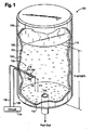
- a perspective view of a first exemplary embodiment of the liquid level sensing system of the present invention is shown in Fig. 1 and is designated generally by reference numeral 100.
- System 100 includes a sensing unit 102 having a first sensing probe 104 and a second sensing probe 106.
- Sensing unit 102 is mounted within a liquid holding tank 108 having at least one side wall 110 and a floor 112, with an outlet orifice 114 formed within floor 112 to allow a liquid 116 to exit the tank 108.
- tank 108 may be a cylindrical enclosed tank configured to hold a predetermined quantity of liquid 116.
- Outlet orifice 114 may interface with a valve or other mechanism that allows for the control of the flow of liquid 116 out of tank 108.
- Liquid level sensing system 100 is well-suited for measuring fuel levels within a fuel tank, especially in aerospace applications.
- liquid tank 108 may be a fuel tank that forms a part of a launch vehicle.
- Tank 108 may hold a liquid hydrogen fuel, a liquid oxygen oxidizer, or other suitable liquid propellants.
- Outlet orifice 114 may be in fluid communication with a combustion chamber, where the liquid fuel draining from tank 108 is ignited to form hot, high temperature gases that are then expanded and accelerated through a nozzle to create thrust for the launch vehicle.
- Sensing unit 102 may include a base 118 (shown in phantom in Fig. 1 ) mounted to an outer surface 120 of side wall 110 or to another structural member, with first and second sensing probes 104, 106 mounted to base 118 and extending through an interior surface 122 of sidewall 110 such that sensing probes 104, 106 extend a predetermined distance into the interior of tank 108.
- Each of the sensing probes 104, 106 may interface with a circuit 124 through one or more leads 126 or by other suitable means.
- Sensing unit 102 functions as a discrete point level sensor capable of detecting the transitions from gas to liquid and liquid to gas within tank 108.
- sensing probes 104, 106 are identical sensing probes as shown in Fig. 2 , having a length z and a diameter d .
- Each sensing probe 104, 106 may also include a sensing element 128.
- Sensing element 128 may be a thermistor, a diode, or any other suitable temperature resistance element such as wound wire made from platinum, nickel, or other suitable material.
- sensing element may be deposited as a film.
- Sensing probes 104, 106 may be elongated and cylindrical in shape with a proximal end 130 mounted to base 118 of sensing unit 102 and a distal end 132 extending into the interior of tank 108. As shown in Fig. 2 , each sensing probe 104, 106 may include a sensing element that includes a wire wound around distal end 132 of the sensing probe for a distance L along the length z of the sensing probe. Each sensing element 128 may be electrically connected to lead 126 and circuit 124 via connectors 134 on proximal end 130 of the sensing probe.
- System 100 exploits the self-heating characteristics of sensing element 128 to determine the liquid level within tank 108. Because the heat transfer properties of gas and liquid are different, the rate of self heating of sensing element 128 depends on whether sensing element 128 is immersed in gas or liquid. Each sensing element 128 of sensing probes 104, 106 is supplied with a constant excitation current sufficient to provide measurable self heating in gas. The degree of self heating is proportional to the power dissipation of sensing element 128, which depends on the element resistance, excitation current, and boundary conditions (liquid or gas). As liquid 116 drains from tank 108, fust sensing probe 104 and second sensing probe 106 each transition from being immersed in liquid to being surrounded completely by gas.
- sensing probes 104, 106 When sensing probes 104, 106 are surrounded by gas, the resistance heating produced by sensing element 128 increases, and the sensed temperature of each element increases. For example, for a sensing probe having an outer diameter of .06 inches, the self-heating rate in liquid nitrogen is 0.028 °C/mW, while the self-heating rate in gaseous nitrogen is .213 °C/mW.
- Each sensing probe 104, 106 produces an output signal proportional to the temperature present at the sensing element on the probe.
- the liquid-to-gas response time of each sensing probe may be influenced by the wetting of the sensing element on the probe, that is, the tendency of the liquid to stick to the surface of the sensing element on the sensing probe. As the element emerges from the liquid, any liquid that clings to the surface will cause a delay in the response time as the liquid evaporates.
- a small resistive element can be used to minimize surface area and increase watt density
- a sensing probe having a smooth surface contour can be used so that there are no cavities to trap liquid
- the excitation current provided to the sensing elements on the probe can be increased, which in turn increases the power and rate of evaporation
- a non-wetting coating such as parylene, can be applied to the sensing probe and sensing element.
- the low surface tension provided by a non-wetting coating promotes shedding of the liquid from the sensing probe to minimize the influence of wetting.
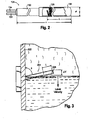
- Fig. 3 illustrates an additional solution to the wetting problem.
- a sensing probe 204 can be mounted at an angle with respect to the liquid level velocity within a tank.
- sensing probe 204 is mounted in such a way that it forms an acute angle with an interior surface 222 of the housing of the tank as well as with the liquid level velocity.
- Liquid level velocity is a vector representing the speed and direction in which the liquid in the tank is moving.
- Mounting sensing probe 204 at an angle effects liquid run-off and level detection resolution.
- liquid run-off is directed away from a sensing element 228 located on the distal end of the sensing probe, which minimizes the wetting delay.
- mounting the sensing probe at an angle presents a tradeoff, because the resolution AY may be compromised as the angle deviates from 90 degrees.
- Fig. 4 illustrates an exemplary embodiment of sensing unit 102 of the liquid level sensing system 100 shown in Fig. 1 .
- Fig. 4 shows the relative placement of sensing probes 104 and 106 of the sensing unit.
- Sensing probes 104 and 106 may be offset in two directions to ensure that both probes are exposed to the same flow of liquid 116 in tank 108. As shown in Fig.
- first sensing probe 104 may be spaced apart from second sensing probe 106 by a lateral distance along an x axis and a distance D y along a y axis, with the y axis being parallel to the liquid level velocity of liquid 116 as the liquid drains from tank, and the x axis being perpendicular to the y axis and generally perpendicular to the sensing probes 104,106.
- the lateral distance D z between first sensing probe 104 and second sensing probe 106 is large enough to prevent the wake produced by first sensing probe 104 from affecting the temperature measurement at second sensing probe 106. Properly spacing the sensing probes ensures that both first sensing probe 104 and second sensing probe 106 are exposed to the same flow of liquid 116.
- First sensing probe 104 produces an output signal representing a first temperature T1 at the first sensing probe
- second sensing probe 106 produces an output signal representing a second temperature T2 at the second sensing probe.
- the difference between the two temperatures (T1-T2) is sent as an input signal to circuit 124, which provides an output proportional to the time rate of change of the difference (T1-T2).
- sensing elements 128 of first and second sensing probes 104,106 each have individual time constants (63.2% response) of 10 seconds, provide a liquid to gas self-heating rise of 20 kelvin (K), and are positioned within the tank 10 seconds apart. In other words, as liquid 116 drains from tank 108, the liquid level reaches second sensing probe 106 ten seconds after reaching first sensing probe 104.
- Figs. 5 through 7 illustrate the draining of liquid 116 from tank 108 over a given time period.
- Fig. 5 illustrates sensing unit 102 with first sensing probe 104 and second sensing probe 106 at an initial time t 0 , with both sensing probes immersed in liquid 116.
- the sensing probes are essentially isothermal, that is, first temperature T1 is equal to second temperature T2 and the difference between the two temperatures (T1-T2) is equal to zero.
- first sensing probe 104 and second sensing probe 106 provide rapid triggering events for detecting levels at first sensing probe 104 and second sensing probe 106, despite using sensing probes with relatively slow response times.
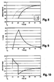
- Figs. 8 through 10 illustrate the changes in first temperature T1, second temperature T2, temperature difference (T1-T2) and the derivative of the temperature difference d(T1-T2)/dt for a given time period during the draining of tank 108.
- An initial time t 0 where the liquid level within the tank is at a predetermined distance above first sensing probe 104, is represented as a beginning point on the abscissa of the each of the plots shown in Figs. 8 through 10 .
- Fig. 8 illustrates the temperature change at both first sensing probe 104 and second sensing probe 106.
- first sensing probe 104 begins to transition from being immersed in liquid to being surrounded by gas 10 seconds after t 0 ;
- second sensing probe 106 begins to transition from being immersed in liquid to being surrounded by gas 10 seconds later, 20 seconds after t 0 .
- both sensing probes are initially at 90 K at the initial time t 0 , that is, the first temperature T1 and the second temperature T2 are both equal to 90 K.
- first temperature T1 measured at first sensing probe 104 begins to gradually increase as a result of the increase in self heating in gas, while T2 remains at 90 K.
- second temperature T2 measured at second sensing probe 106 also begins to gradually increase as a result of the liquid-to-gas transition. Sixty seconds after t 0 , both first temperature T1 and second temperature T2 are have again equilibrated at a temperature of 110 K, given that the level of liquid 116 within tank 108 has now dropped below both first sensing probe 104 and second sensing probe 106 so that both probes are completely surrounded by gas.
- Fig. 9 illustrates how the temperature difference (T1-T2) changes over the same time period mentioned above.
- first temperature T1 and second temperature T2 are equal, so that the temperature difference (T1-T2) is zero.
- T1-T2 begins to rise as first sensing probe transitions from liquid to gas.
- a maximum temperature difference (T1-T2) is reached 20 seconds after t 0 , just before second sensor 106 transitions from liquid to gas.
- Temperature difference (T1-T2) gradually returns to zero as both first and second sensing probes equilibrate at the same gas temperature of 110 K.
- Fig. 10 is a plot of the derivative of the temperature difference (T1-T2) changes over the same time period.
- the derivative of the temperature difference is the time rate of change of the difference between first temperature T1 and second temperature T2, that is, d (T1-T2)/ dt .
- the derivative rapidly peaks 10 seconds after t 0 , when first sensing probe 104 transitions from liquid to gas. After gradually decreasing, the derivative rapidly peaks again, this time in the opposite direction, 20 seconds after t 0 , when second sensing probe 106 transitions from liquid to gas.
- the pulse width-the time between the rapid rise and fall- is directly related to the liquid level velocity because the distance between the two sensing probes is fixed.
- Circuit 124 provides both the excitation and signal conditional for each sensing element 128 of first sensing probe 104 and second sensing probe 106.
- Circuit 124 may include a signal conditioner 136, a difference amplifier 138, a low-pass filter 140, a differentiator 142, and an inverter 144.
- each sensing element 128 of sensing probes 104,106 is supplied with a constant excitation current.
- the current is set to ensure appreciable self heating occurs in the gas present in tank 108. In one exemplary embodiment, the current is set such that the self heating increases by 10° C or more when the sensing probes transition from liquid to gas.
- Signal conditioner 136 may include an operational amplifier U1 configured to function as a first voltage follower and a second operation amplifier U2 configured to function as a second voltage follower.
- the first voltage follower receives a first input signal proportional to the resistance measured at first sensing probe 104 and outputs a first voltage V1.
- the second voltage follower receives a second input signal proportional to the resistance measured at second sensing probe 104 and outputs a second voltage V2.
- Difference amplifier 138 receives first voltage V1 and second voltage V2 as inputs and generates a signal related to the difference between the two input signals (V1-V2). A difference occurs because the resistance element on first sensing probe 104 is physically separated from the resistance element on second sensing probe 106, so that the first resistance element and the second resistance element will sense a liquid to gas transition at different times.
- Low-pass filter 140 receives voltage V3 as input and produces a filtered voltage V4 as output.
- Low-pass filter 140 contains resistors R5, R6. capacitors C1 and C2, and an operational amplifier U4, as shown in Fig. 11 .
- Low-pass filter 140 is used to filter out the high frequency signal above its cutoff frequency (fc).
- the cutoff frequency of the filter is commensurate with the thermal time constant of the resistance elements on the sensing probes so that the filter does not mask the sudden change in the self-heating characteristics of the resistance elements when the sensing probes transition from liquid to gas.
- low-pass filter 140 is a Sallen-Key active filter.
- Differentiation 142 receives voltage V4 from low-pass filter 140 as input and produces a voltage V5 as output.
- differentiator 142 may include capacitor C3, resistors R7 and R8, and an operational amplifier U5.
- the voltage output V5 produced by differentiator 142 is proportional to the time rate of change of input voltage V4 and the current flowing through the capacitor C3. In other words, the faster the input voltage changes, the greater the input current, and the greater the output response.
- Voltage V5 is a constant (-R8 x C3) times the derivative of the input voltage V4 with respect to time.
- the minus sign indicates a 180 degree phase shift because the input signal is connected to the inverting input terminal of operation amplifier U5.
- R8 and C3 influence the gain (i.e. signal amplitude) and circuit response.
- Optimum values for R8 and C3 depend on the desired output signal V5, the circuit response time, operating voltage range, element response, and element time spacing.
- R7 is added to the input as shown in Fig.
- Inverter 144 may optionally be included within circuit 124.
- Inverter 144 includes resistors R9 and R10, and an operational amplifier U6.
- Inverter 144 receives voltage V5 as input and outputs voltage V out .
- the output resistors R9 and R10 have the same resistance value so that voltage V out will be equal to - V5.
- Fig. 12 shows the voltage output data of an embodiment of the liquid level sensing system described in this disclosure.
- the voltage output data demonstrates the rapid response of the differentiator for sensors transitioning between liquid nitrogen and gaseous nitrogen. This data was generated using two temperature sensing probes each having a platinum resistance thermometer with an ice-point resistance of 1000 ohms as the sensing element, with each resistance element receiving an excitation current of 21 miliamperes (mA) using the circuit configuration described above.
- the resistance within resistor R8 was 1.5 megaohms and the capacitance of capacitor C3 was 20 microfarads ( ⁇ F).
- the voltage output from the first and second sensor labeled as Sensor 1 and Sensor 2 in Fig.
- FIG. 12 corresponds to the temperature rise at the first and second sensing probes, as illustrated in Fig. 8 .
- the voltage output from the difference amplifier corresponds to the temperature difference between the first and second sensing probes, as illustrated in Fig. 9 .
- the differentiated output shown in Fig. 12 corresponds to the plot of the time rate of change of the temperature difference measured by the first and second sensing probes, as shown in Fig. 10 .
- the data displayed in Fig. 12 illustrates the abrupt increase and decrease in voltage that permits liquid level sensing system 100 to rapidly detect a discrete point level of liquid within a tank.
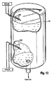
- Fig. 13 illustrates another exemplary embodiment of the liquid level sensing system.
- tank 108 includes a first sensing unit 302 and a second sensing unit 304.
- First and second sensing units 302, 304 function in the same way as sensing unit 102 described above.
- First sensing unit 302 is positioned near the top of tank 108 and functions as a filling sensor, that is, sensing unit 302 is configured to determine when tank 108 has been filled.
- Second sensing unit 304 may be positioned near the bottom of the tank and be configured as a depletion sensor to determine when the tank is nearly empty.
- Fig. 14 illustrates a method 400 of determining the level of liquid in a tank as the liquid drains from the tank.
- a tank having a housing is provided.
- a first temperature sensor connected to the tank housing is provided.
- a second temperature sensor connected to the housing of the tank is provided.
- the first and second temperature sensors are spaced a predetermined distance apart within the tank in the direction of the liquid level velocity.
- the first temperature sensor continuously measures the temperature at the first sensor.
- the second temperature sensor continuously measures the temperature at the second sensor.
- a circuit is provided, the circuit being configured to receive a signal input from the first temperature sensor representing the temperature at the first sensor.
- the circuit receives a signal input from the second temperature sensor representing the temperature at the second sensor.
- the circuit manipulates the first and second input signals, and at step 420, the circuit provides an output signal that is proportional to the time rate of change of the difference between the first signal and the second signal. This method allows for detection of abrupt changes in the time rate of change of the difference between the signals, which serves as an indication of when the liquid in the tank is passing by the sensors.
Landscapes
- Physics & Mathematics (AREA)
- Thermal Sciences (AREA)
- Fluid Mechanics (AREA)
- General Physics & Mathematics (AREA)
- Measurement Of Levels Of Liquids Or Fluent Solid Materials (AREA)
- Level Indicators Using A Float (AREA)
Abstract
Description
- The present invention relates to discrete point liquid level sensing within an enclosure, and more particularly to a rapid-response liquid level sensing system that includes two temperature sensing probes and a circuit that produces an output proportional to the time rate of change of the difference between the two signals received from the temperature sensing probes.
- For aerospace launch vehicle applications using liquid propellant, precisely determining when a fuel tank has been depleted during flight is critically important to ensure proper engine cutoff. Typically, several sensors within a fuel tank of the launch vehicle monitor the liquid level in the fuel tank as the fuel exits the tank. The sensors function to prevent the engines of the launch vehicle from shutting down either too early or too late. An early shutdown could prevent the launch vehicle from reaching orbit; a late shutdown could result in an engine failure.
- Conventional liquid level sensing systems for launch vehicle applications use a bare wire sensing element that adequately meets system response requirements (<160 ms), but is very fragile. The bare wire sensing element consists of a thin platinum wire wrapped loosely around a ceramic card. The wire diameter is extremely thin—about the width of a human hair. The thermal mass of the thin wire is very small, which means that the response time of the sensing element is fast because liquid is quickly shed from the sensing element during the transition from liquid to gas. However, the fragility of the conventional sensing element is problematic, especially for newer launch vehicles that experience significantly higher pyrotechnic shock levels. In addition, at cryogenic temperatures, the low resistance (- 1 ohm) of the conventional liquid level sensors interferes with circuit fault detection.
- There is a compelling need for a liquid level sensing system that provides sufficiently fast response times with higher resistance, while being rugged enough to endure high mechanical shock levels. The present invention addresses this need.
- This disclosure is directed to systems and methods for liquid level sensing using a differentiating output. The systems and methods will be more readily apparent to those having ordinary skill in the art from the following detailed description of the invention taken in conjunction with the several drawings described below.
- A liquid level sensing system is described below. In a first, independent aspect of the invention there is provided a liquid level sensing system that includes a housing or tank configured to hold a liquid, a first temperature sensor connected to the housing and configured to output a first signal representing a first temperature measured at the first temperature sensor, a second temperature sensor connected to the housing and configured to output a second signal representing a second temperature measured at the second temperature sensor, and a circuit configured to receive the first and second signals as input and to provide an output signal proportional to the time rate of change of the difference between the first signal and the second signal.
- In another, independent aspect of the invention there is provided a method of determining the level of liquid in a tank as the liquid drains from the tank is also provided. The method includes the steps of providing a tank having a housing; providing a first temperature sensor and a second temperature sensor, each sensor being connected to the housing and being spaced apart a predetermined distance from one another in the direction of liquid level velocity in the tank; continuously measuring a first temperature at the first temperature sensor, continuously measuring a second temperature at the second temperature sensor; providing a circuit configured to receive a first input signal from the first temperature sensor representing the first temperature and a second input signal from the second temperature sensor representing the second temperature; and manipulating the first and second input signals within the circuit to provide an output signal proportional to the time rate of change of the difference between the first signal and the second signal.
- In a further, independent aspect of the invention there is provided a fuel level sensing system for detecting the filling and draining of fuel within a tank is also provided. The system includes a fuel tank configured to hold a quantity of liquid fuel, a depletion sensing unit mounted within the tank near a bottom portion of the tank, and a filling sensing unit mounted within the tank near a top portion of the tank. The depletion sensing unit includes a first temperature sensor configured to output a first signal representing a first temperature measured at the first temperature sensor, a second temperature sensor configured to output a second signal representing a second temperature measured at the second temperature sensor, and a first circuit configured to receive the first and second signals as input and to provide a first output signal proportional to the time rate of change of the difference between the first signal and the second signal. The filling sensor unit includes a third temperature sensor configured to output a third signal representing a third temperature measured at the third temperature sensor, a fourth temperature sensor configured to output a fourth signal representing a fourth temperature measured at the fourth temperature sensor, and a second circuit configured to receive the third and fourth signals as input and to provide a second output signal proportional to the time rate of change of the difference between the third signal and the fourth signal.
- So that those skilled in the art will readily understand how to implement the systems and methods for liquid level sensing having a differentiating output without undue experimentation, preferred embodiments of the systems and methods will be described in detail below with reference to the following figures:
-
Fig. 1 is a cut-away perspective view of a fuel tank that includes an exemplary embodiment of the liquid level sensing system of the present invention; -
Fig. 2 shows an exemplary embodiment of a resistance element that may be used in the liquid sensing system ofFig. 1 ; - Fi g. 3 shows an exemplary embodiment of a sensor of the liquid sensing system of the present invention, mounted at an angle of less than 90 degrees with respect to the direction of liquid level velocity;
-
Fig. 4 is a plan view of a portion of the sensing system of the present invention, showing the separation between two sensors in both an x direction and a y direction. -
Fig. 5 is a cross-sectional view of the fuel tank ofFig. 1 , showing two sensors spaced apart from one another, with the level of liquid in the tank above both of the sensors; -
Fig. 6 is a cross-sectional view of the fuel tank ofFig.1 , showing two sensors spaced apart from one another, with the level of liquid in the tank between the two sensors; -
Fig. 7 is a cross-sectional view of the fuel tank ofFig. 1 , showing two sensors spaced apart from one another, with the level of liquid in the tank below both of the sensors; -
Fig. 8 is a plot of the temperature (in kelvin) measured over a given time period at a first sensor (T1) and a second sensor (T2) of the liquid level sensing system of the present invention; -
Fig. 9 is a plot of the temperature difference (T1-T2) between the temperatures measured over a given time period at the first sensor (T1) and the second sensor (T2) of the liquid level sensing system of the present invention; -
Fig. 10 is a plot of the time rate of change of the temperature difference (T1-T2) between the temperatures measured over a given time period at the first sensor (T1) and the second sensor (T2) of the liquid level sensing system of the present invention; -
Fig. 11 is a circuit diagram illustrating an exemplary embodiment of a level sensor circuit that may be used to produce the output of the level sensing system; -
Fig. 12 shows a plot of the differential output between a first sensor and a second sensor of the liquid level sensing system of the present invention, demonstrating the rapid response of the differentiator for sensors transitioning between liquid and gas; -
Fig. 13 is a cut-away perspective view of a fuel tank showing another exemplary embodiment of the liquid level sensing system of the present invention, the sensing system including a depletion sensor near the bottom of the tank and a filling sensor near the top of the tank; and -
Fig. 14 shows the steps of an exemplary method of determining the level of liquid in a tank as the liquid drains from the tank, in accordance with the present invention. - This disclosure describes a liquid level sensing system that uses a plurality of discrete-point level sensing elements to rapidly detect the transition from liquid to gas or from gas to liquid within a tank or other enclosure by using a differentiating technique.
- Reference will now be made in detail to the present preferred embodiments of the liquid level sensing system, examples of which are shown in the drawings. For purposes of explanation and illustration, and not limitation, a perspective view of a first exemplary embodiment of the liquid level sensing system of the present invention is shown in
Fig. 1 and is designated generally byreference numeral 100. -
System 100 includes asensing unit 102 having afirst sensing probe 104 and asecond sensing probe 106.Sensing unit 102 is mounted within aliquid holding tank 108 having at least oneside wall 110 and afloor 112, with anoutlet orifice 114 formed withinfloor 112 to allow aliquid 116 to exit thetank 108. As shown inFig. 1 ,tank 108 may be a cylindrical enclosed tank configured to hold a predetermined quantity ofliquid 116.Outlet orifice 114 may interface with a valve or other mechanism that allows for the control of the flow ofliquid 116 out oftank 108. - Liquid
level sensing system 100 is well-suited for measuring fuel levels within a fuel tank, especially in aerospace applications. For example,liquid tank 108 may be a fuel tank that forms a part of a launch vehicle.Tank 108 may hold a liquid hydrogen fuel, a liquid oxygen oxidizer, or other suitable liquid propellants.Outlet orifice 114 may be in fluid communication with a combustion chamber, where the liquid fuel draining fromtank 108 is ignited to form hot, high temperature gases that are then expanded and accelerated through a nozzle to create thrust for the launch vehicle. -
Sensing unit 102 may include a base 118 (shown in phantom inFig. 1 ) mounted to anouter surface 120 ofside wall 110 or to another structural member, with first andsecond sensing probes base 118 and extending through aninterior surface 122 ofsidewall 110 such thatsensing probes tank 108. Each of thesensing probes circuit 124 through one or more leads 126 or by other suitable means. -
Sensing unit 102 functions as a discrete point level sensor capable of detecting the transitions from gas to liquid and liquid to gas withintank 108. In one exemplary embodiment,sensing probes Fig. 2 , having a length z and a diameter d. Eachsensing probe sensing element 128. Sensingelement 128 may be a thermistor, a diode, or any other suitable temperature resistance element such as wound wire made from platinum, nickel, or other suitable material. In one exemplary embodiment, sensing element may be deposited as a film.Sensing probes proximal end 130 mounted tobase 118 ofsensing unit 102 and adistal end 132 extending into the interior oftank 108. As shown inFig. 2 , eachsensing probe distal end 132 of the sensing probe for a distance L along the length z of the sensing probe. Eachsensing element 128 may be electrically connected to lead 126 andcircuit 124 viaconnectors 134 onproximal end 130 of the sensing probe. -
System 100 exploits the self-heating characteristics ofsensing element 128 to determine the liquid level withintank 108. Because the heat transfer properties of gas and liquid are different, the rate of self heating ofsensing element 128 depends on whethersensing element 128 is immersed in gas or liquid. Eachsensing element 128 of sensing probes 104, 106 is supplied with a constant excitation current sufficient to provide measurable self heating in gas. The degree of self heating is proportional to the power dissipation ofsensing element 128, which depends on the element resistance, excitation current, and boundary conditions (liquid or gas). Asliquid 116 drains fromtank 108,fust sensing probe 104 andsecond sensing probe 106 each transition from being immersed in liquid to being surrounded completely by gas. When sensing probes 104, 106 are surrounded by gas, the resistance heating produced by sensingelement 128 increases, and the sensed temperature of each element increases. For example, for a sensing probe having an outer diameter of .06 inches, the self-heating rate in liquid nitrogen is 0.028 °C/mW, while the self-heating rate in gaseous nitrogen is .213 °C/mW. Eachsensing probe - The liquid-to-gas response time of each sensing probe may be influenced by the wetting of the sensing element on the probe, that is, the tendency of the liquid to stick to the surface of the sensing element on the sensing probe. As the element emerges from the liquid, any liquid that clings to the surface will cause a delay in the response time as the liquid evaporates. This effect can be mitigated in several ways: a small resistive element can be used to minimize surface area and increase watt density; a sensing probe having a smooth surface contour can be used so that there are no cavities to trap liquid; the excitation current provided to the sensing elements on the probe can be increased, which in turn increases the power and rate of evaporation; and a non-wetting coating such as parylene, can be applied to the sensing probe and sensing element. The low surface tension provided by a non-wetting coating promotes shedding of the liquid from the sensing probe to minimize the influence of wetting.
-
Fig. 3 illustrates an additional solution to the wetting problem. As shown, asensing probe 204 can be mounted at an angle with respect to the liquid level velocity within a tank. In other words, sensingprobe 204 is mounted in such a way that it forms an acute angle with an interior surface 222 of the housing of the tank as well as with the liquid level velocity. Liquid level velocity is a vector representing the speed and direction in which the liquid in the tank is moving. - Mounting
sensing probe 204 at an angle effects liquid run-off and level detection resolution. By forming an acute angle with respect to the tank housing and the liquid level velocity, or in other words, an angle that is less than 90 degrees, liquid run-off is directed away from asensing element 228 located on the distal end of the sensing probe, which minimizes the wetting delay. However, mounting the sensing probe at an angle presents a tradeoff, because the resolution AY may be compromised as the angle deviates from 90 degrees. Resolution (ΔY) is defined as follows:
Where θ0 = tan-1(d/L), θ = mounting angle, L = winding length, and d = diameter. The inventors have determined that an optimum angle for mounting the sensing probe to minimize wetting delay without significantly compromising resolution of the sensing element is approximately 75 degrees. -
Fig. 4 illustrates an exemplary embodiment ofsensing unit 102 of the liquidlevel sensing system 100 shown inFig. 1 .Fig. 4 shows the relative placement of sensing probes 104 and 106 of the sensing unit. Sensing probes 104 and 106 may be offset in two directions to ensure that both probes are exposed to the same flow ofliquid 116 intank 108. As shown inFig. 4 ,first sensing probe 104 may be spaced apart fromsecond sensing probe 106 by a lateral distance along an x axis and a distance Dy along a y axis, with the y axis being parallel to the liquid level velocity ofliquid 116 as the liquid drains from tank, and the x axis being perpendicular to the y axis and generally perpendicular to the sensing probes 104,106. The lateral distance Dz betweenfirst sensing probe 104 andsecond sensing probe 106 is large enough to prevent the wake produced byfirst sensing probe 104 from affecting the temperature measurement atsecond sensing probe 106. Properly spacing the sensing probes ensures that bothfirst sensing probe 104 andsecond sensing probe 106 are exposed to the same flow ofliquid 116. -
First sensing probe 104 produces an output signal representing a first temperature T1 at the first sensing probe, andsecond sensing probe 106 produces an output signal representing a second temperature T2 at the second sensing probe. The difference between the two temperatures (T1-T2) is sent as an input signal tocircuit 124, which provides an output proportional to the time rate of change of the difference (T1-T2). Using two sensing probes minimizes the influence of changing temperature and flow withintank 108 on the determination of the level ofliquid 116 within the tank. - In one exemplary embodiment, sensing
elements 128 of first and second sensing probes 104,106 each have individual time constants (63.2% response) of 10 seconds, provide a liquid to gas self-heating rise of 20 kelvin (K), and are positioned within thetank 10 seconds apart. In other words, asliquid 116 drains fromtank 108, the liquid level reachessecond sensing probe 106 ten seconds after reachingfirst sensing probe 104. -
Figs. 5 through 7 illustrate the draining of liquid 116 fromtank 108 over a given time period.Fig. 5 illustrates sensingunit 102 withfirst sensing probe 104 andsecond sensing probe 106 at an initial time t0 , with both sensing probes immersed inliquid 116. At initial time t0 , the sensing probes are essentially isothermal, that is, first temperature T1 is equal to second temperature T2 and the difference between the two temperatures (T1-T2) is equal to zero. - As shown in
Fig. 6 , as the level ofliquid 116 drops belowfirst sensing probe 104, the difference (T1-T2) begins to increase. The rate of change of this difference is nearly instantaneous at the liquid-to-gas transition. As the liquid level approachessecond sensing probe 106, the difference (T1-T2) approaches a maximum with the rate of change gradually decreasing. Assecond sensing probe 106 transitions from being immersed in liquid to being surrounded by gas, as shown inFig. 7 . the difference (T1-T2) begins to decrease and the rate of change of this difference rapidly changes in the opposite direction. This offset configuration offirst sensing probe 104 andsecond sensing probe 106 provides rapid triggering events for detecting levels atfirst sensing probe 104 andsecond sensing probe 106, despite using sensing probes with relatively slow response times. -
Figs. 8 through 10 illustrate the changes in first temperature T1, second temperature T2, temperature difference (T1-T2) and the derivative of the temperature difference d(T1-T2)/dt for a given time period during the draining oftank 108. An initial time t0 , where the liquid level within the tank is at a predetermined distance abovefirst sensing probe 104, is represented as a beginning point on the abscissa of the each of the plots shown inFigs. 8 through 10 . -
Fig. 8 illustrates the temperature change at bothfirst sensing probe 104 andsecond sensing probe 106. As the liquid drains fromtank 108,first sensing probe 104 begins to transition from being immersed in liquid to being surrounded bygas 10 seconds after t0 ;second sensing probe 106 begins to transition from being immersed in liquid to being surrounded bygas 10 seconds later, 20 seconds after t0 . As shown, both sensing probes are initially at 90 K at the initial timet0 , that is, the first temperature T1 and the second temperature T2 are both equal to 90 K. Ten seconds after t0 , first temperature T1 measured atfirst sensing probe 104 begins to gradually increase as a result of the increase in self heating in gas, while T2 remains at 90 K. Twenty seconds after t0 , second temperature T2, measured atsecond sensing probe 106 also begins to gradually increase as a result of the liquid-to-gas transition. Sixty seconds after t0 , both first temperature T1 and second temperature T2 are have again equilibrated at a temperature of 110 K, given that the level ofliquid 116 withintank 108 has now dropped below bothfirst sensing probe 104 andsecond sensing probe 106 so that both probes are completely surrounded by gas. -
Fig. 9 illustrates how the temperature difference (T1-T2) changes over the same time period mentioned above. At initial time t0 , first temperature T1 and second temperature T2 are equal, so that the temperature difference (T1-T2) is zero. Ten seconds after t0, the temperature difference (T1-T2) begins to rise as first sensing probe transitions from liquid to gas. A maximum temperature difference (T1-T2) is reached 20 seconds after t0, just beforesecond sensor 106 transitions from liquid to gas. Temperature difference (T1-T2) gradually returns to zero as both first and second sensing probes equilibrate at the same gas temperature of 110 K. -
Fig. 10 is a plot of the derivative of the temperature difference (T1-T2) changes over the same time period. The derivative of the temperature difference is the time rate of change of the difference between first temperature T1 and second temperature T2, that is, d(T1-T2)/dt. The derivative rapidly peaks 10 seconds after t 0, whenfirst sensing probe 104 transitions from liquid to gas. After gradually decreasing, the derivative rapidly peaks again, this time in the opposite direction, 20 seconds after t 0, whensecond sensing probe 106 transitions from liquid to gas. The pulse width-the time between the rapid rise and fall-is directly related to the liquid level velocity because the distance between the two sensing probes is fixed. These rapid peaks in the time rate of change of the difference d(T1-T2)/dt can be used to trigger point level indications with rapid response time. By feeding signals representing first temperature T1 and second temperature T2 from two individual sensing probes into a differentiating circuit, the level of liquid within a tank can be determined with a response time that is faster than what either of the sensors would be capable of individually. -
Fig. 11 is a circuit diagram showing an exemplary embodiment ofcircuit 124 of liquidlevel sensing system 100.Circuit 124 provides both the excitation and signal conditional for eachsensing element 128 offirst sensing probe 104 andsecond sensing probe 106.Circuit 124 may include asignal conditioner 136, adifference amplifier 138, a low-pass filter 140, adifferentiator 142, and aninverter 144. - As shown in
Fig. 11 , eachsensing element 128 of sensing probes 104,106 is supplied with a constant excitation current. The current is set to ensure appreciable self heating occurs in the gas present intank 108. In one exemplary embodiment, the current is set such that the self heating increases by 10° C or more when the sensing probes transition from liquid to gas.Signal conditioner 136 may include an operational amplifier U1 configured to function as a first voltage follower and a second operation amplifier U2 configured to function as a second voltage follower. The first voltage follower receives a first input signal proportional to the resistance measured atfirst sensing probe 104 and outputs a first voltage V1. Similarly, the second voltage follower receives a second input signal proportional to the resistance measured atsecond sensing probe 104 and outputs a second voltage V2. -
Difference amplifier 138 receives first voltage V1 and second voltage V2 as inputs and generates a signal related to the difference between the two input signals (V1-V2). A difference occurs because the resistance element onfirst sensing probe 104 is physically separated from the resistance element onsecond sensing probe 106, so that the first resistance element and the second resistance element will sense a liquid to gas transition at different times. The difference amplifier includes resistors R1, R2, R3, R4, and an operation amplifier U3. In the exemplary embodiment shown, resistors R1, R2, R3, and R4 have equal resistance values, so that an output voltage V3 ofdifference amplifier 138 is equal to the difference between V1 and V2, that is, V3 =(V1-V2). - Low-
pass filter 140 receives voltage V3 as input and produces a filtered voltage V4 as output. Low-pass filter 140 contains resistors R5, R6. capacitors C1 and C2, and an operational amplifier U4, as shown inFig. 11 . Low-pass filter 140 is used to filter out the high frequency signal above its cutoff frequency (fc). The cutoff frequency is determined by the following equation:
In one exemplary embodiment, the cutoff frequency of the filter is commensurate with the thermal time constant of the resistance elements on the sensing probes so that the filter does not mask the sudden change in the self-heating characteristics of the resistance elements when the sensing probes transition from liquid to gas. In one exemplary embodiment, low-pass filter 140 is a Sallen-Key active filter. -
Differentiation 142 receives voltage V4 from low-pass filter 140 as input and produces a voltage V5 as output. As shown inFig. 11 ,differentiator 142 may include capacitor C3, resistors R7 and R8, and an operational amplifier U5. The voltage output V5 produced bydifferentiator 142 is proportional to the time rate of change of input voltage V4 and the current flowing through the capacitor C3. In other words, the faster the input voltage changes, the greater the input current, and the greater the output response. - Voltage V5 is a constant (-R8 x C3) times the derivative of the input voltage V4 with respect to time. The minus sign indicates a 180 degree phase shift because the input signal is connected to the inverting input terminal of operation amplifier U5. The general equation for the output voltage V5 is:

Parameters R8 and C3 influence the gain (i.e. signal amplitude) and circuit response. Optimum values for R8 and C3 depend on the desired output signal V5, the circuit response time, operating voltage range, element response, and element time spacing. R7 is added to the input as shown inFig. 11 to reduce the overall closed-loop gain of the circuit at high frequencies to the ratio R8/R7 (with capacitor C3 looking like a short). The low frequency gain is still driven by R8 and C3, as before. The cutoff frequency of the differentiator, where these two effects meet, is determined by R7 and C3, according to the expression:
R7 must also be selected based on circuit conditions. In general, decreasing R7 improves circuit response but increases susceptibility to noise and circuit instabilities. Increasing R7 improves circuit stability and reduces high frequency noise but slows circuit response. -
Inverter 144 may optionally be included withincircuit 124.Inverter 144 includes resistors R9 and R10, and an operational amplifier U6.Inverter 144 receives voltage V5 as input and outputs voltage Vout. In one exemplary embodiment, the output resistors R9 and R10 have the same resistance value so that voltage Vout will be equal to - V5. -
Fig. 12 shows the voltage output data of an embodiment of the liquid level sensing system described in this disclosure. The voltage output data demonstrates the rapid response of the differentiator for sensors transitioning between liquid nitrogen and gaseous nitrogen. This data was generated using two temperature sensing probes each having a platinum resistance thermometer with an ice-point resistance of 1000 ohms as the sensing element, with each resistance element receiving an excitation current of 21 miliamperes (mA) using the circuit configuration described above. In the differentiator, the resistance within resistor R8 was 1.5 megaohms and the capacitance of capacitor C3 was 20 microfarads (µF). The voltage output from the first and second sensor, labeled asSensor 1 andSensor 2 inFig. 12 , corresponds to the temperature rise at the first and second sensing probes, as illustrated inFig. 8 . The voltage output from the difference amplifier corresponds to the temperature difference between the first and second sensing probes, as illustrated inFig. 9 . Finally, the differentiated output shown inFig. 12 corresponds to the plot of the time rate of change of the temperature difference measured by the first and second sensing probes, as shown inFig. 10 . The data displayed inFig. 12 illustrates the abrupt increase and decrease in voltage that permits liquidlevel sensing system 100 to rapidly detect a discrete point level of liquid within a tank. -
Fig. 13 illustrates another exemplary embodiment of the liquid level sensing system. In this embodiment,tank 108 includes afirst sensing unit 302 and asecond sensing unit 304. First andsecond sensing units unit 102 described above.First sensing unit 302 is positioned near the top oftank 108 and functions as a filling sensor, that is, sensingunit 302 is configured to determine whentank 108 has been filled.Second sensing unit 304 may be positioned near the bottom of the tank and be configured as a depletion sensor to determine when the tank is nearly empty. -
Fig. 14 illustrates amethod 400 of determining the level of liquid in a tank as the liquid drains from the tank. Atstep 402 ofmethod 400, a tank having a housing is provided. Next, at step 404, a first temperature sensor connected to the tank housing is provided. Atstep 406, a second temperature sensor connected to the housing of the tank is provided. Atstep 408, the first and second temperature sensors are spaced a predetermined distance apart within the tank in the direction of the liquid level velocity. Atstep 410, the first temperature sensor continuously measures the temperature at the first sensor. Atstep 412, the second temperature sensor continuously measures the temperature at the second sensor. Atstep 414, a circuit is provided, the circuit being configured to receive a signal input from the first temperature sensor representing the temperature at the first sensor. Atstep 416, the circuit receives a signal input from the second temperature sensor representing the temperature at the second sensor. Atstep 418, the circuit manipulates the first and second input signals, and atstep 420, the circuit provides an output signal that is proportional to the time rate of change of the difference between the first signal and the second signal. This method allows for detection of abrupt changes in the time rate of change of the difference between the signals, which serves as an indication of when the liquid in the tank is passing by the sensors. - While the systems and methods for liquid level sensing having a differentiating output have been shown and described with reference to preferred embodiments, those skilled in the art will readily appreciate that various modifications may be made to the systems and methods of this disclosure without departing from the scope of the invention as described in the appended claims and their equivalents.
Claims (15)
- A liquid level sensing system, comprising:a housing configured to hold a liquid;a first temperature sensor connected to the housing and configured to output a first signal representing a first temperature measured at the first temperature sensor;a second temperature sensor connected to the housing and configured to output a second signal representing a second temperature measured at the second temperature sensor;a circuit configured to receive the first and second signals as input and to provide an output signal proportional to the time rate of change of the difference between the first signal and the second signal.
- The sensing system of claim 1, wherein the first temperature sensor and the second temperature sensor are spaced apart by a predetermined distance in the direction of liquid level velocity.
- The sensing system of claim 1, wherein the first temperature sensor and the second temperature sensor are spaced apart by a predetermined distance in the direction of liquid level velocity as well as in the direction perpendicular to liquid level velocity.
- The sensing system of claim 1, wherein the first and second sensors each comprise an elongate body with a proximal end attached to a base and a distal end positioned away from the base.
- The sensing system of claim 4, wherein the elongate body is supported within the housing such that the distal end of the elongate body is a predetermined distance above the proximal end of the elongate body such that an acute angle is formed between the elongate body and the direction of liquid level velocity.
- The sensing system of claim 5, wherein the acute angle is approximately 75 degrees.
- The sending system of claim 4, wherein each of the sensors further comprises a resistive sensing element supported by at least a portion of the distal end of the elongate body.
- The sensing system of claim 7, wherein the resistive sensing element is deposited as at least one of wrapped wire or film, and/or the resistive sensing element is comprised of platinum.
- The sensing system of claim 7, wherein each of the sensors further comprises at least one of:a smooth surface configured to facilitate liquid run-off away from the resistive sensing element; ora non-wetting coating to facilitate liquid run-off away from the resistive sensing element.
- The sensing system of claim 1, wherein the circuit comprises at least one of:-a signal conditioner;a difference amplifier;.a low-pass filter;a differentiator;an inverter.
- A method of determining the level of liquid in a tank as the liquid drains from the tank, the method comprising:providing a tank having a housing;providing a first temperature sensor and a second temperature sensor, each sensor being connected to the housing and being spaced apart a predetermined distance from one another in the direction of liquid level velocity in the tank;continuously measuring a first temperature at the first temperature sensor;continuously measuring a second temperature at the second temperature sensor;providing a circuit configured to receive a first input signal from the first temperature sensor representing the first temperature and a second input signal from the second temperature sensor representing the second temperature; andmanipulating the first and second input signals within the circuit to provide an output signal proportional to the time rate of change of the difference between the first signal and the second signal.
- The method of claim 11, further comprising spacing apart the first temperature sensor and the second temperature sensor by a predetermined distance in the direction perpendicular to liquid level velocity.
- The method of claim 11, wherein the step of providing a first temperature sensor and a second temperature sensor comprises providing a sensors that each include an elongate body with a proximal end attached to a base and a distal end positioned away from the base.
- The method of claim 13, further comprising mounting the elongate body to the housing such that the distal end of the elongate body is a predetermined distance above the proximal end of the elongate body such that an acute angle is formed between the elongate body and the direction of liquid level velocity, whereinoptionally:the acute angle is approximately 75 degrees.
- A liquid level sensing system according to claim1, wherein the housing comprises a tank configured to hold a quantity of liquid fuel, the system is for detecting the filling and draining of fuel within the tank, and the system comprises:a depletion sensing unit mounted within the tank near a bottom portion of the tank and comprising the first temperature sensor, the second temperature sensor, and the first circuit; anda filling sensing unit mounted within the tank near a top portion of the tank, the filling sensing unit comprising a third temperature sensor configured to output a third signal representing a third temperature measured at the third temperature sensor, a fourth temperature sensor configured to output a fourth signal representing a fourth temperature measured at the fourth temperature sensor, and a second circuit configured to receive the third and fourth signals as input and to provide a second output signal proportional to the time rate of change of the difference between the third signal and the fourth signal.
Applications Claiming Priority (1)
| Application Number | Priority Date | Filing Date | Title |
|---|---|---|---|
| US12/842,308 US8438919B2 (en) | 2010-07-23 | 2010-07-23 | Systems and methods for liquid level sensing having a differentiating output |
Publications (3)
| Publication Number | Publication Date |
|---|---|
| EP2410301A2 true EP2410301A2 (en) | 2012-01-25 |
| EP2410301A3 EP2410301A3 (en) | 2012-06-13 |
| EP2410301B1 EP2410301B1 (en) | 2019-12-11 |
Family
ID=44503647
Family Applications (1)
| Application Number | Title | Priority Date | Filing Date |
|---|---|---|---|
| EP11250652.2A Active EP2410301B1 (en) | 2010-07-23 | 2011-07-11 | Systems and methods for liquid level sensing having a differentiating output |
Country Status (4)
| Country | Link |
|---|---|
| US (1) | US8438919B2 (en) |
| EP (1) | EP2410301B1 (en) |
| JP (1) | JP2012027024A (en) |
| CA (1) | CA2745615C (en) |
Families Citing this family (19)
| Publication number | Priority date | Publication date | Assignee | Title |
|---|---|---|---|---|
| FR2978543B1 (en) * | 2011-07-28 | 2014-03-07 | Sc2N Sa | DEVICE FOR MEASURING A LIQUID LEVEL |
| US9357881B2 (en) * | 2012-03-31 | 2016-06-07 | Pitco Frialator, Inc. | Oil level detection system for deep fat fryer |
| JP6212467B2 (en) * | 2014-11-13 | 2017-10-11 | 株式会社フジキン | Liquid level gauge and liquid raw material vaporizer |
| JP2017008773A (en) * | 2015-06-19 | 2017-01-12 | 愛三工業株式会社 | Oil storage amount determination device |
| FR3060117B1 (en) * | 2016-12-09 | 2019-08-16 | Airbus Defence And Space Sas | METHOD OF THERMALLY MEASURING THE RESERVOIR OF A SPACE VEHICLE AND A SPACE VEHICLE EQUIPPED WITH MEANS FOR IMPLEMENTING SUCH A METHOD |
| US20200163829A1 (en) * | 2018-11-26 | 2020-05-28 | Djo, Llc | Cold therapy cooler having a color changing indicator |
| BR112021010672A2 (en) | 2018-12-03 | 2021-08-24 | Hewlett-Packard Development Company, L.P. | logic circuits |
| CA3121146C (en) | 2018-12-03 | 2024-05-28 | Hewlett-Packard Development Company, L.P. | Logic circuitry package for controlling ic2 traffic |
| PT3681723T (en) | 2018-12-03 | 2021-08-27 | Hewlett Packard Development Co | Logic circuitry |
| EP3688645A1 (en) | 2018-12-03 | 2020-08-05 | Hewlett-Packard Development Company, L.P. | Logic circuitry package |
| US11338586B2 (en) | 2018-12-03 | 2022-05-24 | Hewlett-Packard Development Company, L.P. | Logic circuitry |
| PL3682359T3 (en) | 2018-12-03 | 2021-05-17 | Hewlett-Packard Development Company, L.P. | Logic circuitry |
| EP3695334A1 (en) | 2018-12-03 | 2020-08-19 | Hewlett Packard Enterprise Development Company LP | Logic circuitry |
| CN113165395B (en) | 2018-12-03 | 2023-01-10 | 惠普发展公司,有限责任合伙企业 | logic circuit system |
| US10894423B2 (en) | 2018-12-03 | 2021-01-19 | Hewlett-Packard Development Company, L.P. | Logic circuitry |
| CN113168453A (en) | 2018-12-03 | 2021-07-23 | 惠普发展公司,有限责任合伙企业 | Logic circuitry packaging |
| US11407229B2 (en) | 2019-10-25 | 2022-08-09 | Hewlett-Packard Development Company, L.P. | Logic circuitry package |
| WO2021221678A1 (en) | 2020-04-30 | 2021-11-04 | Hewlett-Packard Development Company, L.P. | Logic circuitry package for print apparatus |
| KR102414034B1 (en) * | 2021-09-28 | 2022-06-28 | 주식회사 헥사 | Level sensor for liquid hydrogen container for drone, and pressure control device and method for liquid hydrogen tank using the same |
Family Cites Families (21)
| Publication number | Priority date | Publication date | Assignee | Title |
|---|---|---|---|---|
| DE869701C (en) | 1951-04-03 | 1953-03-05 | Siemens Ag | Arrangement for measuring the liquid level by means of a heated resistor |
| JPS5286359A (en) * | 1976-01-13 | 1977-07-18 | Doryokuro Kakunenryo | Method of measuring level of liquid metal |
| US4205237A (en) | 1977-12-16 | 1980-05-27 | Nartron Corporation | Liquid level sensor, pump system means and circuit means |
| JPS54118330A (en) * | 1978-03-08 | 1979-09-13 | Hitachi Ltd | Detection of surface position of molten metal |
| JPS5716317A (en) * | 1980-07-04 | 1982-01-27 | Hitachi Ltd | Check sensor for molten metal level position |
| US4358955A (en) * | 1980-09-29 | 1982-11-16 | Technomadic Corporation | Liquid level gauge |
| DE3101302A1 (en) | 1981-01-16 | 1982-08-05 | Bio-Melktechnik Swiss Hoefelmayr & Co, 9052 Niederteufen, Aargau | "MILK FLOW METER" |
| JPS628019A (en) * | 1985-07-04 | 1987-01-16 | Mitsubishi Electric Corp | Sensor for detecting liquid level of low temperature liquefied gas |
| JPH0552633A (en) * | 1991-08-28 | 1993-03-02 | Mitsubishi Electric Corp | Level detector for ice storage tank |
| JP3009809B2 (en) * | 1993-08-26 | 2000-02-14 | 株式会社鷺宮製作所 | Liquid level detecting device in liquid material storage container for semiconductor processing |
| JPH10281851A (en) * | 1997-04-11 | 1998-10-23 | Ishikawajima Harima Heavy Ind Co Ltd | Liquid level measurement method for glass melting furnace and liquid level sensor used in this method |
| JP3399815B2 (en) * | 1997-12-15 | 2003-04-21 | リンナイ株式会社 | Water presence detector |
| JP2000097749A (en) * | 1998-09-18 | 2000-04-07 | Natl Space Development Agency Of Japan | Thermal diffusion type liquid level sensor |
| US6536276B2 (en) * | 2001-02-27 | 2003-03-25 | Rosemont Aerospace Inc. | Apparatus and method to non-intrusively measure the level of liquid in a sealed container |
| AUPR689601A0 (en) | 2001-08-08 | 2001-08-30 | Refrigerant Monitoring Systems Pty Ltd | Liquid level sensor |
| US7334455B2 (en) * | 2003-10-31 | 2008-02-26 | Mitsui Mining & Smelting Co., Ltd. | Leak detector of liquid in tank |
| US7302846B2 (en) * | 2004-03-12 | 2007-12-04 | Hadala Anthony J | Temperature-sensing device for determining the level of a fluid |
| KR100882479B1 (en) | 2004-10-07 | 2009-02-06 | 엘지전자 주식회사 | Thermosensitive water level sensing apparatus and fluid tank having the same |
| US7596998B2 (en) | 2006-07-19 | 2009-10-06 | Therm-O-Disc, Incorporated | Liquid level sensor using thick film substrate |
| US7874724B2 (en) * | 2007-04-11 | 2011-01-25 | Trane International Inc. | Method for sensing the liquid level in a compressor |
| DE102008022363B4 (en) | 2008-05-06 | 2012-01-19 | Areva Np Gmbh | Method and device for monitoring the level of a liquid in a liquid container |
-
2010
- 2010-07-23 US US12/842,308 patent/US8438919B2/en active Active
-
2011
- 2011-07-07 CA CA2745615A patent/CA2745615C/en active Active
- 2011-07-11 EP EP11250652.2A patent/EP2410301B1/en active Active
- 2011-07-20 JP JP2011158749A patent/JP2012027024A/en active Pending
Non-Patent Citations (1)
| Title |
|---|
| None |
Also Published As
| Publication number | Publication date |
|---|---|
| US8438919B2 (en) | 2013-05-14 |
| EP2410301A3 (en) | 2012-06-13 |
| EP2410301B1 (en) | 2019-12-11 |
| US20120017675A1 (en) | 2012-01-26 |
| JP2012027024A (en) | 2012-02-09 |
| CA2745615C (en) | 2019-10-01 |
| CA2745615A1 (en) | 2012-01-23 |
Similar Documents
| Publication | Publication Date | Title |
|---|---|---|
| EP2410301B1 (en) | Systems and methods for liquid level sensing having a differentiating output | |
| US4590797A (en) | Thermal system for measuring liquid levels | |
| Sakurai et al. | Transient pool boiling heat transfer—Part 1: Incipient boiling superheat | |
| EP1567842B1 (en) | Thermometry probe calibration method | |
| EP0242412B1 (en) | Method and apparatus for measuring fluid flow | |
| US4848147A (en) | Thermal transient anemometer | |
| US9810566B2 (en) | Robust dynamical method and device for detecting the level of a liquid using resistance temperature detectors | |
| US10533883B2 (en) | Thermal, flow measuring device with diagnostic function | |
| US7007549B2 (en) | AC type flowmeter and method of mapping flow rate data for the same | |
| US6431010B1 (en) | Optical fiber-based fluid flow anemometer | |
| EP0805968B1 (en) | Real-time measuring method | |
| CN116569008A (en) | Thermometer with diagnostic function | |
| US6498566B1 (en) | Method for measuring fluid level | |
| JPS61153555A (en) | Method and device for detecting presence of substance or generation of change immediately before physical state change in fluid | |
| Van den Broek et al. | Bubble nucleation in an explosive micro-bubble actuator | |
| US7013714B2 (en) | Viscosity measurement apparatus | |
| US11402348B2 (en) | Bubble detection module comprising a nanowire | |
| EP3047284B1 (en) | Sensor for high temperature turbulent flow | |
| JP2008524559A (en) | Method and apparatus for monitoring material | |
| US7066022B2 (en) | Airspeed sensor and method for operating an airspeed sensor | |
| JPS58129335A (en) | Correcting device for meters with temperature detecting unit | |
| EP1041375A1 (en) | Determining heat transfer | |
| EP4478005A1 (en) | Dual-use level and temperature probe | |
| RU2295115C2 (en) | Liquid level control gauge | |
| Romera-Guereca et al. | Explosive vaporization and microbubble oscillations on submicron width thin film strip heaters |
Legal Events
| Date | Code | Title | Description |
|---|---|---|---|
| 17P | Request for examination filed |
Effective date: 20110719 |
|
| AK | Designated contracting states |
Kind code of ref document: A2 Designated state(s): AL AT BE BG CH CY CZ DE DK EE ES FI FR GB GR HR HU IE IS IT LI LT LU LV MC MK MT NL NO PL PT RO RS SE SI SK SM TR |
|
| AX | Request for extension of the european patent |
Extension state: BA ME |
|
| PUAI | Public reference made under article 153(3) epc to a published international application that has entered the european phase |
Free format text: ORIGINAL CODE: 0009012 |
|
| PUAL | Search report despatched |
Free format text: ORIGINAL CODE: 0009013 |
|
| AK | Designated contracting states |
Kind code of ref document: A3 Designated state(s): AL AT BE BG CH CY CZ DE DK EE ES FI FR GB GR HR HU IE IS IT LI LT LU LV MC MK MT NL NO PL PT RO RS SE SI SK SM TR |
|
| AX | Request for extension of the european patent |
Extension state: BA ME |
|
| RIC1 | Information provided on ipc code assigned before grant |
Ipc: G01F 23/24 20060101AFI20120510BHEP |
|
| STAA | Information on the status of an ep patent application or granted ep patent |
Free format text: STATUS: EXAMINATION IS IN PROGRESS |
|
| 17Q | First examination report despatched |
Effective date: 20171122 |
|
| GRAP | Despatch of communication of intention to grant a patent |
Free format text: ORIGINAL CODE: EPIDOSNIGR1 |
|
| STAA | Information on the status of an ep patent application or granted ep patent |
Free format text: STATUS: GRANT OF PATENT IS INTENDED |
|
| INTG | Intention to grant announced |
Effective date: 20190624 |
|
| GRAS | Grant fee paid |
Free format text: ORIGINAL CODE: EPIDOSNIGR3 |
|
| GRAA | (expected) grant |
Free format text: ORIGINAL CODE: 0009210 |
|
| STAA | Information on the status of an ep patent application or granted ep patent |
Free format text: STATUS: THE PATENT HAS BEEN GRANTED |
|
| AK | Designated contracting states |
Kind code of ref document: B1 Designated state(s): AL AT BE BG CH CY CZ DE DK EE ES FI FR GB GR HR HU IE IS IT LI LT LU LV MC MK MT NL NO PL PT RO RS SE SI SK SM TR |
|
| REG | Reference to a national code |
Ref country code: GB Ref legal event code: FG4D |
|
| REG | Reference to a national code |
Ref country code: CH Ref legal event code: EP |
|
| REG | Reference to a national code |
Ref country code: AT Ref legal event code: REF Ref document number: 1212645 Country of ref document: AT Kind code of ref document: T Effective date: 20191215 |
|
| REG | Reference to a national code |
Ref country code: DE Ref legal event code: R096 Ref document number: 602011063915 Country of ref document: DE |
|
| REG | Reference to a national code |
Ref country code: IE Ref legal event code: FG4D |
|
| REG | Reference to a national code |
Ref country code: NL Ref legal event code: MP Effective date: 20191211 |
|
| REG | Reference to a national code |
Ref country code: LT Ref legal event code: MG4D |
|
| PG25 | Lapsed in a contracting state [announced via postgrant information from national office to epo] |
Ref country code: BG Free format text: LAPSE BECAUSE OF FAILURE TO SUBMIT A TRANSLATION OF THE DESCRIPTION OR TO PAY THE FEE WITHIN THE PRESCRIBED TIME-LIMIT Effective date: 20200311 Ref country code: GR Free format text: LAPSE BECAUSE OF FAILURE TO SUBMIT A TRANSLATION OF THE DESCRIPTION OR TO PAY THE FEE WITHIN THE PRESCRIBED TIME-LIMIT Effective date: 20200312 Ref country code: FI Free format text: LAPSE BECAUSE OF FAILURE TO SUBMIT A TRANSLATION OF THE DESCRIPTION OR TO PAY THE FEE WITHIN THE PRESCRIBED TIME-LIMIT Effective date: 20191211 Ref country code: LT Free format text: LAPSE BECAUSE OF FAILURE TO SUBMIT A TRANSLATION OF THE DESCRIPTION OR TO PAY THE FEE WITHIN THE PRESCRIBED TIME-LIMIT Effective date: 20191211 Ref country code: ES Free format text: LAPSE BECAUSE OF FAILURE TO SUBMIT A TRANSLATION OF THE DESCRIPTION OR TO PAY THE FEE WITHIN THE PRESCRIBED TIME-LIMIT Effective date: 20191211 Ref country code: SE Free format text: LAPSE BECAUSE OF FAILURE TO SUBMIT A TRANSLATION OF THE DESCRIPTION OR TO PAY THE FEE WITHIN THE PRESCRIBED TIME-LIMIT Effective date: 20191211 Ref country code: LV Free format text: LAPSE BECAUSE OF FAILURE TO SUBMIT A TRANSLATION OF THE DESCRIPTION OR TO PAY THE FEE WITHIN THE PRESCRIBED TIME-LIMIT Effective date: 20191211 Ref country code: NO Free format text: LAPSE BECAUSE OF FAILURE TO SUBMIT A TRANSLATION OF THE DESCRIPTION OR TO PAY THE FEE WITHIN THE PRESCRIBED TIME-LIMIT Effective date: 20200311 |
|
| PG25 | Lapsed in a contracting state [announced via postgrant information from national office to epo] |
Ref country code: RS Free format text: LAPSE BECAUSE OF FAILURE TO SUBMIT A TRANSLATION OF THE DESCRIPTION OR TO PAY THE FEE WITHIN THE PRESCRIBED TIME-LIMIT Effective date: 20191211 Ref country code: HR Free format text: LAPSE BECAUSE OF FAILURE TO SUBMIT A TRANSLATION OF THE DESCRIPTION OR TO PAY THE FEE WITHIN THE PRESCRIBED TIME-LIMIT Effective date: 20191211 |
|
| PG25 | Lapsed in a contracting state [announced via postgrant information from national office to epo] |
Ref country code: AL Free format text: LAPSE BECAUSE OF FAILURE TO SUBMIT A TRANSLATION OF THE DESCRIPTION OR TO PAY THE FEE WITHIN THE PRESCRIBED TIME-LIMIT Effective date: 20191211 |
|
| PG25 | Lapsed in a contracting state [announced via postgrant information from national office to epo] |
Ref country code: NL Free format text: LAPSE BECAUSE OF FAILURE TO SUBMIT A TRANSLATION OF THE DESCRIPTION OR TO PAY THE FEE WITHIN THE PRESCRIBED TIME-LIMIT Effective date: 20191211 Ref country code: PT Free format text: LAPSE BECAUSE OF FAILURE TO SUBMIT A TRANSLATION OF THE DESCRIPTION OR TO PAY THE FEE WITHIN THE PRESCRIBED TIME-LIMIT Effective date: 20200506 Ref country code: CZ Free format text: LAPSE BECAUSE OF FAILURE TO SUBMIT A TRANSLATION OF THE DESCRIPTION OR TO PAY THE FEE WITHIN THE PRESCRIBED TIME-LIMIT Effective date: 20191211 Ref country code: RO Free format text: LAPSE BECAUSE OF FAILURE TO SUBMIT A TRANSLATION OF THE DESCRIPTION OR TO PAY THE FEE WITHIN THE PRESCRIBED TIME-LIMIT Effective date: 20191211 Ref country code: EE Free format text: LAPSE BECAUSE OF FAILURE TO SUBMIT A TRANSLATION OF THE DESCRIPTION OR TO PAY THE FEE WITHIN THE PRESCRIBED TIME-LIMIT Effective date: 20191211 |
|
| PG25 | Lapsed in a contracting state [announced via postgrant information from national office to epo] |
Ref country code: IS Free format text: LAPSE BECAUSE OF FAILURE TO SUBMIT A TRANSLATION OF THE DESCRIPTION OR TO PAY THE FEE WITHIN THE PRESCRIBED TIME-LIMIT Effective date: 20200411 Ref country code: SK Free format text: LAPSE BECAUSE OF FAILURE TO SUBMIT A TRANSLATION OF THE DESCRIPTION OR TO PAY THE FEE WITHIN THE PRESCRIBED TIME-LIMIT Effective date: 20191211 Ref country code: SM Free format text: LAPSE BECAUSE OF FAILURE TO SUBMIT A TRANSLATION OF THE DESCRIPTION OR TO PAY THE FEE WITHIN THE PRESCRIBED TIME-LIMIT Effective date: 20191211 |
|
| REG | Reference to a national code |
Ref country code: DE Ref legal event code: R097 Ref document number: 602011063915 Country of ref document: DE |
|
| REG | Reference to a national code |
Ref country code: AT Ref legal event code: MK05 Ref document number: 1212645 Country of ref document: AT Kind code of ref document: T Effective date: 20191211 |
|
| PLBE | No opposition filed within time limit |
Free format text: ORIGINAL CODE: 0009261 |
|
| STAA | Information on the status of an ep patent application or granted ep patent |
Free format text: STATUS: NO OPPOSITION FILED WITHIN TIME LIMIT |
|
| PG25 | Lapsed in a contracting state [announced via postgrant information from national office to epo] |
Ref country code: DK Free format text: LAPSE BECAUSE OF FAILURE TO SUBMIT A TRANSLATION OF THE DESCRIPTION OR TO PAY THE FEE WITHIN THE PRESCRIBED TIME-LIMIT Effective date: 20191211 |
|
| 26N | No opposition filed |
Effective date: 20200914 |
|
| PG25 | Lapsed in a contracting state [announced via postgrant information from national office to epo] |
Ref country code: PL Free format text: LAPSE BECAUSE OF FAILURE TO SUBMIT A TRANSLATION OF THE DESCRIPTION OR TO PAY THE FEE WITHIN THE PRESCRIBED TIME-LIMIT Effective date: 20191211 Ref country code: AT Free format text: LAPSE BECAUSE OF FAILURE TO SUBMIT A TRANSLATION OF THE DESCRIPTION OR TO PAY THE FEE WITHIN THE PRESCRIBED TIME-LIMIT Effective date: 20191211 Ref country code: SI Free format text: LAPSE BECAUSE OF FAILURE TO SUBMIT A TRANSLATION OF THE DESCRIPTION OR TO PAY THE FEE WITHIN THE PRESCRIBED TIME-LIMIT Effective date: 20191211 |
|
| PG25 | Lapsed in a contracting state [announced via postgrant information from national office to epo] |
Ref country code: IT Free format text: LAPSE BECAUSE OF FAILURE TO SUBMIT A TRANSLATION OF THE DESCRIPTION OR TO PAY THE FEE WITHIN THE PRESCRIBED TIME-LIMIT Effective date: 20191211 |
|
| PG25 | Lapsed in a contracting state [announced via postgrant information from national office to epo] |
Ref country code: MC Free format text: LAPSE BECAUSE OF FAILURE TO SUBMIT A TRANSLATION OF THE DESCRIPTION OR TO PAY THE FEE WITHIN THE PRESCRIBED TIME-LIMIT Effective date: 20191211 |
|
| REG | Reference to a national code |
Ref country code: CH Ref legal event code: PL |
|
| REG | Reference to a national code |
Ref country code: BE Ref legal event code: MM Effective date: 20200731 |
|
| PG25 | Lapsed in a contracting state [announced via postgrant information from national office to epo] |
Ref country code: LU Free format text: LAPSE BECAUSE OF NON-PAYMENT OF DUE FEES Effective date: 20200711 Ref country code: LI Free format text: LAPSE BECAUSE OF NON-PAYMENT OF DUE FEES Effective date: 20200731 Ref country code: CH Free format text: LAPSE BECAUSE OF NON-PAYMENT OF DUE FEES Effective date: 20200731 |
|
| PG25 | Lapsed in a contracting state [announced via postgrant information from national office to epo] |
Ref country code: BE Free format text: LAPSE BECAUSE OF NON-PAYMENT OF DUE FEES Effective date: 20200731 |
|
| PG25 | Lapsed in a contracting state [announced via postgrant information from national office to epo] |
Ref country code: IE Free format text: LAPSE BECAUSE OF NON-PAYMENT OF DUE FEES Effective date: 20200711 |
|
| PG25 | Lapsed in a contracting state [announced via postgrant information from national office to epo] |
Ref country code: TR Free format text: LAPSE BECAUSE OF FAILURE TO SUBMIT A TRANSLATION OF THE DESCRIPTION OR TO PAY THE FEE WITHIN THE PRESCRIBED TIME-LIMIT Effective date: 20191211 Ref country code: MT Free format text: LAPSE BECAUSE OF FAILURE TO SUBMIT A TRANSLATION OF THE DESCRIPTION OR TO PAY THE FEE WITHIN THE PRESCRIBED TIME-LIMIT Effective date: 20191211 Ref country code: CY Free format text: LAPSE BECAUSE OF FAILURE TO SUBMIT A TRANSLATION OF THE DESCRIPTION OR TO PAY THE FEE WITHIN THE PRESCRIBED TIME-LIMIT Effective date: 20191211 |
|
| PG25 | Lapsed in a contracting state [announced via postgrant information from national office to epo] |
Ref country code: MK Free format text: LAPSE BECAUSE OF FAILURE TO SUBMIT A TRANSLATION OF THE DESCRIPTION OR TO PAY THE FEE WITHIN THE PRESCRIBED TIME-LIMIT Effective date: 20191211 |
|
| PGFP | Annual fee paid to national office [announced via postgrant information from national office to epo] |
Ref country code: GB Payment date: 20250619 Year of fee payment: 15 |
|
| PGFP | Annual fee paid to national office [announced via postgrant information from national office to epo] |
Ref country code: FR Payment date: 20250620 Year of fee payment: 15 |
|
| PGFP | Annual fee paid to national office [announced via postgrant information from national office to epo] |
Ref country code: DE Payment date: 20250620 Year of fee payment: 15 |
|
| P01 | Opt-out of the competence of the unified patent court (upc) registered |
Free format text: CASE NUMBER: UPC_APP_0016525_2410301/2025 Effective date: 20251209 |