EP2410267A2 - Refrigerator - Google Patents
Refrigerator Download PDFInfo
- Publication number
- EP2410267A2 EP2410267A2 EP11174327A EP11174327A EP2410267A2 EP 2410267 A2 EP2410267 A2 EP 2410267A2 EP 11174327 A EP11174327 A EP 11174327A EP 11174327 A EP11174327 A EP 11174327A EP 2410267 A2 EP2410267 A2 EP 2410267A2
- Authority
- EP
- European Patent Office
- Prior art keywords
- pipe
- guide pipe
- drain guide
- defrosting water
- refrigerator
- Prior art date
- Legal status (The legal status is an assumption and is not a legal conclusion. Google has not performed a legal analysis and makes no representation as to the accuracy of the status listed.)
- Granted
Links
Images



Classifications
-
- F—MECHANICAL ENGINEERING; LIGHTING; HEATING; WEAPONS; BLASTING
- F25—REFRIGERATION OR COOLING; COMBINED HEATING AND REFRIGERATION SYSTEMS; HEAT PUMP SYSTEMS; MANUFACTURE OR STORAGE OF ICE; LIQUEFACTION SOLIDIFICATION OF GASES
- F25D—REFRIGERATORS; COLD ROOMS; ICE-BOXES; COOLING OR FREEZING APPARATUS NOT OTHERWISE PROVIDED FOR
- F25D21/00—Defrosting; Preventing frosting; Removing condensed or defrost water
- F25D21/04—Preventing the formation of frost or condensate
-
- F—MECHANICAL ENGINEERING; LIGHTING; HEATING; WEAPONS; BLASTING
- F25—REFRIGERATION OR COOLING; COMBINED HEATING AND REFRIGERATION SYSTEMS; HEAT PUMP SYSTEMS; MANUFACTURE OR STORAGE OF ICE; LIQUEFACTION SOLIDIFICATION OF GASES
- F25D—REFRIGERATORS; COLD ROOMS; ICE-BOXES; COOLING OR FREEZING APPARATUS NOT OTHERWISE PROVIDED FOR
- F25D19/00—Arrangement or mounting of refrigeration units with respect to devices or objects to be refrigerated, e.g. infrared detectors
-
- F—MECHANICAL ENGINEERING; LIGHTING; HEATING; WEAPONS; BLASTING
- F25—REFRIGERATION OR COOLING; COMBINED HEATING AND REFRIGERATION SYSTEMS; HEAT PUMP SYSTEMS; MANUFACTURE OR STORAGE OF ICE; LIQUEFACTION SOLIDIFICATION OF GASES
- F25D—REFRIGERATORS; COLD ROOMS; ICE-BOXES; COOLING OR FREEZING APPARATUS NOT OTHERWISE PROVIDED FOR
- F25D21/00—Defrosting; Preventing frosting; Removing condensed or defrost water
- F25D21/14—Collecting or removing condensed and defrost water; Drip trays
-
- F—MECHANICAL ENGINEERING; LIGHTING; HEATING; WEAPONS; BLASTING
- F25—REFRIGERATION OR COOLING; COMBINED HEATING AND REFRIGERATION SYSTEMS; HEAT PUMP SYSTEMS; MANUFACTURE OR STORAGE OF ICE; LIQUEFACTION SOLIDIFICATION OF GASES
- F25D—REFRIGERATORS; COLD ROOMS; ICE-BOXES; COOLING OR FREEZING APPARATUS NOT OTHERWISE PROVIDED FOR
- F25D2321/00—Details or arrangements for defrosting; Preventing frosting; Removing condensed or defrost water, not provided for in other groups of this subclass
- F25D2321/14—Collecting condense or defrost water; Removing condense or defrost water
- F25D2321/141—Removal by evaporation
- F25D2321/1412—Removal by evaporation using condenser heat or heat of desuperheaters
-
- F—MECHANICAL ENGINEERING; LIGHTING; HEATING; WEAPONS; BLASTING
- F25—REFRIGERATION OR COOLING; COMBINED HEATING AND REFRIGERATION SYSTEMS; HEAT PUMP SYSTEMS; MANUFACTURE OR STORAGE OF ICE; LIQUEFACTION SOLIDIFICATION OF GASES
- F25D—REFRIGERATORS; COLD ROOMS; ICE-BOXES; COOLING OR FREEZING APPARATUS NOT OTHERWISE PROVIDED FOR
- F25D2321/00—Details or arrangements for defrosting; Preventing frosting; Removing condensed or defrost water, not provided for in other groups of this subclass
- F25D2321/14—Collecting condense or defrost water; Removing condense or defrost water
- F25D2321/143—Collecting condense or defrost water; Removing condense or defrost water characterised by means to fix, clamp, or connect water pipes or evaporation trays
-
- F—MECHANICAL ENGINEERING; LIGHTING; HEATING; WEAPONS; BLASTING
- F25—REFRIGERATION OR COOLING; COMBINED HEATING AND REFRIGERATION SYSTEMS; HEAT PUMP SYSTEMS; MANUFACTURE OR STORAGE OF ICE; LIQUEFACTION SOLIDIFICATION OF GASES
- F25D—REFRIGERATORS; COLD ROOMS; ICE-BOXES; COOLING OR FREEZING APPARATUS NOT OTHERWISE PROVIDED FOR
- F25D2321/00—Details or arrangements for defrosting; Preventing frosting; Removing condensed or defrost water, not provided for in other groups of this subclass
- F25D2321/14—Collecting condense or defrost water; Removing condense or defrost water
- F25D2321/146—Collecting condense or defrost water; Removing condense or defrost water characterised by the pipes or pipe connections
Definitions
- Embodiments relate to a refrigerator, and more particularly, to a refrigerator that is able to carry out a heat exchange action between a hot pipe and a drain guide pipe more desirably, wherein the drain guide pipe guides defrosting water.
- a refrigerator is a home appliance that stores food in a storage chamber at a low temperature by using a refrigerant cycle. Refrigerators may be used for other purposes than food storage and may be used outside the home.
- the refrigerator comprises a main body, a cool air generating chamber provided in the main body, having an evaporator to generate the cool air, and a machine chamber provided with a compressor and a condenser.
- the cool air generating chamber is provided with a defrosting water tray that receives defrosting water generated in the evaporator during a defrosting action.
- the defrosting water is collected in the defrosting water tray in such a manner that it downwardly moves along a drain guide pipe connected to the defrosting water tray and is collected in a water collecting tray provided below the main body.
- the compressor and the condenser are connected with each other by a hot pipe, which guides a refrigerant discharged from the compressor to the condenser.
- the refrigerant discharged from the compressor is at a high temperature state, whereby the hot pipe has a very high surface temperature.
- the hot pipe is connected with the compressor such that it is arranged inside or outside the main body, whereby the hot pipe is connected with the condenser through the water collecting tray.
- the hot pipe can prevent condensation from occurring on the surface of the main body, and can serve to evaporate the water collected in the water collecting tray.
- the refrigerator according to the related art has a problem in that the hot pipe is spaced apart from the drain guide pipe for guiding defrosting water, so as not to carry out heat exchange therebetween.
- Embodiments are directed to a refrigerator that substantially obviates one or more problems due to limitations and disadvantages of the related art.
- Embodiments provide a refrigerator that is able to carry out a heat exchange action between a hot pipe and a drain guide pipe, which guides defrosting water, whereby an evaporation action of defrosting water flowing along the drain guide pipe can be carried out more desirably.
- Embodiments provide a refrigerator that does not need a separate fixing member for fixing a hot pipe by providing the hot pipe outside defrosting water or receiving the hot pipe inside the defrosting water.
- a refrigerator comprises a cool air generating chamber and a machine chamber provided above a main body; a defrosting water tray provided inside the cool air generating chamber; a water collecting tray provided below the main body; a hot pipe connecting a compressor with a condenser through the water collecting tray, the compressor and the condenser being provided in the machine chamber; and a drain guide pipe mounted outside the main body and connected to the defrosting water tray and the water collecting tray to guide the defrosting water discharged from the defrosting water tray to the water collecting tray, wherein the hot pipe is provided inside or outside the drain guide pipe.
- Embodiments have advantages as follows.
- the refrigerator is able to carry out a heat exchange action between the hot pipe and the drain guide pipe, which guides defrosting water, whereby an evaporation action of defrosting water flowing along the drain guide pipe can be carried out more desirably.
- the refrigerator does not need a separate fixing member for fixing the hot pipe by providing the hot pipe outside defrosting water or receiving the hot pipe inside the defrosting water.
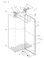
- FIG. 1 is a front perspective view illustrating a refrigerator
- FIG. 2 is a rear perspective view illustrating the refrigerator
- FIG. 3 is a rear view illustrating a state that a drain guide pipe and a hot pipe are provided in the refrigerator
- FIG. 4 is a perspective view illustrating a state that a connection pipe is provided in the refrigerator.
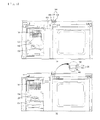
- FIG. 5 is a plane sectional view illustrating a refrigerator.
- a refrigerator includes a main body 10, a freezing chamber 11 and a refrigerating chamber 12.
- a cool air generating chamber 100 is provided above the freezing chamber 11, and a machine chamber 200 is provided above the refrigerating chamber 12.
- the cool air generating chamber 100 includes an evaporator 110, a defrosting water tray 120 and a cool air fain unit 130.
- the defrosting water tray 120 is provided below the evaporator 110 to collect defrosting water generated by the evaporator 110 when a defrosting action of the evaporator 110 occurs.
- the cool air fan unit 130 is arranged at the front of the evaporator 110, and serves to pull up the air in the freezing chamber 11 so as to carry out heat exchange between the air and the evaporator 110 and then send the cooled air to the freezing chamber.
- a discharge outlet 140 is provided at the front of the cool air fan unit 130 to discharge the air of the freezing chamber, and a suction inlet (not shown) is provided at the rear of the evaporator 110 to suck the air of the freezing chamber 11 towards the evaporator 110.
- a water collecting tray 300 is provided below the main body 10 to collect defrosting water collected in the defrosting water tray 120.
- the defrosting water collected in the defrosting water tray 120 moves under the guide of a drain guide pipe 400 and a connection pipe 410, wherein the drain guide pipe 400 is arranged outside the rear of the main body 10, and the connection pipe 410 connects the drain guide pipe 400 with the defrosting water tray 120.
- a mounting groove (not shown) having a shape corresponding to a sectional shape of the drain guide pipe 400 is provided at the rear of the body 10 to mount the drain guide pipe 400. Accordingly, the drain guide pipe 400 is mounted in and fixed to the mounting groove (not shown).
- the drain guide pipe 400 is arranged up and down outside the rear of the main body 10.
- the upper side of the drain guide pipe 400 is connected with the connection pipe 410, and the lower side of the drain guide pipe 400 is connected with the water collecting tray 300.
- the machine chamber 200 is partitioned from the cool air generating chamber 100 and arranged next to the cool air generating chamber 100.
- a compressor 210 compressing a refrigerant, a condenser 220 condensing the compressed refrigerant, and a condensing fan 230 provided next to the condenser 220 to blow the air to the condenser 220 are provided in the cool air generating chamber.
- the compressor 210 and the condenser 220 are connected with each other through a hot pipe 500.
- the hot pipe 500 is connected with the compressor 210 and the condenser 220 and arranged along the rear outside of the main body 10.
- the hot pipe 500 is arranged over a certain area inside the water collecting tray 300 provided below the main body 10.
- the hot pipe 500 includes a first hot pipe 510 connected with the compressor 210, a second hot pipe 520 connected with the condenser 220, and a third hot pipe 530 extended from the first and second hot pipes 510 and 520 connected with the compressor 210 and the condenser 220 and arranged over a predetermined area of the water collecting tray 300.
- the cool air inside the first to third hot pipes 510, 520 and 530 is at a high temperature state, if the cool air is in contact with the defrosting water in the drain guide pipe 400 and the water collecting tray 300, it may evaporate the defrosting water.
- the third hot pipe 530 arranged in the water collecting tray 300 is widely arranged over the surface of the water collecting tray 300 and maintains at a high surface temperature due to the refrigerant of high temperature as described above, it serves to transfer heat to the collected defrosting water widely spread in the surface of the water collecting tray 300 and evaporate the defrosting water.
- the first and second hot pipes 510 and 520 arranged at the rear of the main body 10 may be received in the drain guide pipe 400 or may be coupled to the external surface of the drain guide pipe 400.
- the defrosting water inside the drain guide pipe 400 may be evaporated naturally.
- first and second hot pipes 510 and 520 are mounted inside the drain guide pipe 400 or on the external surface of the drain guide pipe 400, a separate mounting structure such as a clip or holder for fixing the first and second hot pipes 510 and 520 to the main body is not required.
- the hot pipe 500 mounted in the drain guide pipe 400 includes the first hot pipe 510 connected with the compressor 210 and the second hot pipe 520 connected with the condenser 220 as described above.
- the first and second hot pipes 510 and 520 are provided up and down in parallel with the drain guide pipe 400.
- a mounting groove 600 is arranged up and down outside the rear of the main body 10, and the drain guide pipe 400 is also arranged up and down in the mounting groove 600.
- connection hole 610 is provided above the mounting groove 600, wherein one end of the connection pipe 410 connected with the defrosting water tray 120 is mounted in the connection hole 610.
- connection pipe 410 After the defrosting water collected in the defrosting water tray 120 is guided by the connection pipe 410, it moves to the drain guide pipe 400 by passing through the connection hole 610.
- An inlet 411 is formed at one side above the drain guide pipe 400 and is connected with the connection hole 610 to flow the defrosting water thereinto.
- An outlet 420 is provided at one side below the drain guide pipe 400 and is connected with the water collecting tray 300 provided below the main body 10 to discharge the water in the drain guide pipe 400 towards the water collecting tray.
- the drain guide pipe 400 has a hollow rectangular shape and the mounting groove 600 also has a hollow rectangular shape corresponding to the shape of the drain guide pipe 400.
- the shape of the drain guide pipe 400 is not limited to the rectangular shape. Namely, various modifications can be made in the shape of the drain guide pipe 400.
- the drain guide pipe 400 may have a cylindrical shape and the mounting groove 600 may also have a cylindrical shape corresponding to the shape of the drain guide pipe 400.
- An incline portion 430 is formed below the drain guide pipe 400 and guides the defrosting water in the drain guide pipe 400 to be dropped down, whereby the defrosting water can easily be moved to the water collecting tray 300.
- the incline portion 430 is downwardly inclined towards the front from the rear to prevent the defrosting water from remaining below the drain guide pipe 400.
- the incline portion 430 serves to guide the defrosting water to be quickly moved to the water collecting tray 300 in such a manner that the defrosting water downwardly moves along the incline portion 430.
- the hot pipe 500 includes the first hot pipe 510 connected with the compressor 210, the second hot pipe 520 connected with the condenser 220, and the third hot pipe 530 arranged inside the water collecting tray 300.
- the first hot pipe 510 connected with the compressor 210 and the second hot pipe 520 connected with the condenser 220 are projected from the inside of the machine chamber 200 to the outside thereof, and pass through the upper surface of the drain guide pipe 400 or one side above the drain guide pipe 400.
- first hot pipe 510 and the second hot pipe 520 are connected with the third hot pipe 530 arranged inside the water collecting tray 300 by passing through the outlet 420 provided below the drain guide pipe 400.
- the third hot pipe 530 is windingly arranged in the water collecting tray 300 to occupy a certain area inside the water collecting tray 300, whereby the third hot pipe 530 can be easily in contact with the defrosting water collected in the water collecting tray 300.
- the upper end of the drain guide pipe 400 is not extended to the upper end of the main body 10 but spaced apart from the lower end of the machine chamber 200 as much as a certain distance D.
- connection hole 610 is lower than the lower end of the machine chamber 200.
- the distance between the upper end of the drain guide pipe 400 and the connection hole 610 is not a space where the water can move, it may be a dead space.
- the upper end of the drain guide pipe 400 is located directly above the connection hole 610.
- connection hole 610 is arranged to be a little lower than the discharge outlet of the defrosting water tray 120.
- connection pipe 410 One end of the connection pipe 410 is arranged at the discharge outlet of the defrosting water tray 120, and the other end of the connection pipe 410 is arranged to be connected with the connection hole 610.
- connection pipe 411 includes one end 411 connected with the discharge outlet provided at a side of the defrosting water tray 120 and the other end 412 connected with the connection hole, as described above.
- connection pipe 411 partially has a winding shape.
- connection pipe 411 has a winding shape to prevent the defrosting water from flowing too fast while receiving the defrosting water much more than that received in a straight shape pipe.
- connection pipe 411 is windingly formed to control velocity of flow of the defrosting water.
- the one end 411 is higher than the other end 412 to easily move the defrosting water flown into the one end 411 to the drain guide pipe 400 after moving the defrosting water to the other end 412.
- Support portions 411a and 412a are respectively provided at the one end 411 and the other end 412 of the connection pipe 410.
- the support portions 411a and 412a are in surface contact with the side of the defrosting water tray 120 and the inside of the main body 10 where the connection hole 610 is formed.
- support portions 411a and 412a are provided in a cylindrical shape, their shape is not limited to the cylindrical shape.
- the support portions 411a and 412a may be provided in other shape such as a rectangular shape.
- Each of the support portions 411a and 412a has a size greater than a diameter of the drain guide pipe 410 arranged between the support portions 411a and 412a.
- each of the support portions 411a and 412a has a surface area
- the surface of each of the support portions 411a and 412a can be coated with an adhesive, whereby the support portions 411a and 412a can easily be attached into the main body 10 and the defrosting water tray 120.
- a side support portion 413 is provided at a portion adjacent to the other end 412 of the connection pipe 410 in a plate shape.
- the side support portion 413 is in surface contact with the outside of an inner case of the refrigerator.
- the support portion 412a provided at the other end of the connection pipe 410 is attached to an inner wall of an outer case constituting the main body, and the side support portion 413 is supported to the outer wall of the inner case arranged inside the outer case.
- the hot pipe 500 is arranged inside the drain guide pipe 400 in parallel with the drain guide pipe 400 so as to be in contact with the defrosting water flowing inside the drain guide pipe 400, whereby it can evaporate the defrosting water.
- the refrigerant flowing inside the hot pipe 500 carries out heat exchange with the defrosting water, since its temperature may be lower, condensing efficiency at the condenser can be enhanced.
- the hot pipe 500 is fitted into a groove shaped fixing portion 440 provided on the external surface of the drain guide pipe 400 to carry out heat exchange with the drain guide pipe 400.
- the hot pipe 500 is arranged on the external surface of the drain guide pipe 400, it is advantageous in that the defrosting water flows to carry out heat exchange with the external air as well as the drain guide pipe 400 of which temperature has been lowered.
- a cool air generating action of the evaporator 110 disclosed in FIG. 1 is stopped and a defrosting heater (not shown) provided in the evaporator 110 carries out defrosting action for removing frost formed in the evaporator 110, the frost is melted and becomes a defrosting water, and the defrosting water is dropped in the defrosting water tray 120 and collected therein.
- the defrosting water tray 120 Since the bottom surface of the defrosting water tray 120 is included towards an outlet provided in the defrosting water tray 120 and connected with the connection pipe 120, the defrosting water moves to the outlet.
- the defrosting water that has passed through the outlet flows into the drain guide pipe 400 under the guide of the connection pipe 410.
- the defrosting water inside the hot pipe 500 and the drain guide pipe 400 or the defrosting water in the water collecting tray 120 is in contact with the hot pipe 500, the defrosting water can be evaporated.
- the hot pipe 500 is mounted to pass through the inside of the drain guide pipe 400, or is fixed to the outside of the drain guide pipe, a separate fixing structure for fixing the hot pipe 400 is not required.
Landscapes
- Engineering & Computer Science (AREA)
- Chemical & Material Sciences (AREA)
- Combustion & Propulsion (AREA)
- Physics & Mathematics (AREA)
- Mechanical Engineering (AREA)
- Thermal Sciences (AREA)
- General Engineering & Computer Science (AREA)
- Removal Of Water From Condensation And Defrosting (AREA)
Abstract
Description
- The present invention relates to the field of refrigeration. Embodiments relate to a refrigerator, and more particularly, to a refrigerator that is able to carry out a heat exchange action between a hot pipe and a drain guide pipe more desirably, wherein the drain guide pipe guides defrosting water.
- A refrigerator is a home appliance that stores food in a storage chamber at a low temperature by using a refrigerant cycle. Refrigerators may be used for other purposes than food storage and may be used outside the home.
- Specifically, the refrigerator comprises a main body, a cool air generating chamber provided in the main body, having an evaporator to generate the cool air, and a machine chamber provided with a compressor and a condenser.
- The cool air generating chamber is provided with a defrosting water tray that receives defrosting water generated in the evaporator during a defrosting action. The defrosting water is collected in the defrosting water tray in such a manner that it downwardly moves along a drain guide pipe connected to the defrosting water tray and is collected in a water collecting tray provided below the main body.
- The compressor and the condenser are connected with each other by a hot pipe, which guides a refrigerant discharged from the compressor to the condenser. The refrigerant discharged from the compressor is at a high temperature state, whereby the hot pipe has a very high surface temperature.
- The hot pipe is connected with the compressor such that it is arranged inside or outside the main body, whereby the hot pipe is connected with the condenser through the water collecting tray. As a result, the hot pipe can prevent condensation from occurring on the surface of the main body, and can serve to evaporate the water collected in the water collecting tray.
- However, the refrigerator according to the related art has a problem in that the hot pipe is spaced apart from the drain guide pipe for guiding defrosting water, so as not to carry out heat exchange therebetween.
- Embodiments are directed to a refrigerator that substantially obviates one or more problems due to limitations and disadvantages of the related art.
- Embodiments provide a refrigerator that is able to carry out a heat exchange action between a hot pipe and a drain guide pipe, which guides defrosting water, whereby an evaporation action of defrosting water flowing along the drain guide pipe can be carried out more desirably.
- Embodiments provide a refrigerator that does not need a separate fixing member for fixing a hot pipe by providing the hot pipe outside defrosting water or receiving the hot pipe inside the defrosting water.
- In one aspect, a refrigerator comprises a cool air generating chamber and a machine chamber provided above a main body; a defrosting water tray provided inside the cool air generating chamber; a water collecting tray provided below the main body; a hot pipe connecting a compressor with a condenser through the water collecting tray, the compressor and the condenser being provided in the machine chamber; and a drain guide pipe mounted outside the main body and connected to the defrosting water tray and the water collecting tray to guide the defrosting water discharged from the defrosting water tray to the water collecting tray, wherein the hot pipe is provided inside or outside the drain guide pipe.
- Embodiments have advantages as follows.
- The refrigerator is able to carry out a heat exchange action between the hot pipe and the drain guide pipe, which guides defrosting water, whereby an evaporation action of defrosting water flowing along the drain guide pipe can be carried out more desirably.
- Also, the refrigerator does not need a separate fixing member for fixing the hot pipe by providing the hot pipe outside defrosting water or receiving the hot pipe inside the defrosting water.
- In the drawings:
-
FIG. 1 is a front perspective view illustrating a refrigerator; -
FIG. 2 is a rear perspective view illustrating the refrigerator; -
FIG. 3 is a rear view illustrating a state that a drain guide pipe and a hot pipe are provided in the refrigerator; -
FIG. 4 is a perspective view illustrating a state that a connection pipe is provided in the refrigerator; and -
FIG. 5 is a plane sectional view illustrating a refrigerator. - Reference will now be made in detail to certain embodiments illustrated in the accompanying drawings. Wherever possible, the same reference numbers will be used throughout the drawings to refer to the same or like parts.
- As shown in
FIG. 1 , a refrigerator includes amain body 10, a freezing chamber 11 and a refrigeratingchamber 12. A coolair generating chamber 100 is provided above the freezing chamber 11, and amachine chamber 200 is provided above the refrigeratingchamber 12. - The cool
air generating chamber 100 includes anevaporator 110, a defrostingwater tray 120 and a coolair fain unit 130. - The defrosting
water tray 120 is provided below theevaporator 110 to collect defrosting water generated by theevaporator 110 when a defrosting action of theevaporator 110 occurs. - The cool
air fan unit 130 is arranged at the front of theevaporator 110, and serves to pull up the air in the freezing chamber 11 so as to carry out heat exchange between the air and theevaporator 110 and then send the cooled air to the freezing chamber. - A
discharge outlet 140 is provided at the front of the coolair fan unit 130 to discharge the air of the freezing chamber, and a suction inlet (not shown) is provided at the rear of theevaporator 110 to suck the air of the freezing chamber 11 towards theevaporator 110. - A
water collecting tray 300 is provided below themain body 10 to collect defrosting water collected in the defrostingwater tray 120. - The defrosting water collected in the defrosting water tray 120 moves under the guide of a
drain guide pipe 400 and aconnection pipe 410, wherein thedrain guide pipe 400 is arranged outside the rear of themain body 10, and theconnection pipe 410 connects thedrain guide pipe 400 with the defrostingwater tray 120. - A mounting groove (not shown) having a shape corresponding to a sectional shape of the
drain guide pipe 400 is provided at the rear of thebody 10 to mount thedrain guide pipe 400. Accordingly, thedrain guide pipe 400 is mounted in and fixed to the mounting groove (not shown). - The
drain guide pipe 400 is arranged up and down outside the rear of themain body 10. - The upper side of the
drain guide pipe 400 is connected with theconnection pipe 410, and the lower side of thedrain guide pipe 400 is connected with thewater collecting tray 300. - The
machine chamber 200 is partitioned from the coolair generating chamber 100 and arranged next to the coolair generating chamber 100. - A
compressor 210 compressing a refrigerant, acondenser 220 condensing the compressed refrigerant, and acondensing fan 230 provided next to thecondenser 220 to blow the air to thecondenser 220 are provided in the cool air generating chamber. - The
compressor 210 and thecondenser 220 are connected with each other through ahot pipe 500. Thehot pipe 500 is connected with thecompressor 210 and thecondenser 220 and arranged along the rear outside of themain body 10. In more detail, thehot pipe 500 is arranged over a certain area inside thewater collecting tray 300 provided below themain body 10. - In other words, the
hot pipe 500 includes a firsthot pipe 510 connected with thecompressor 210, a secondhot pipe 520 connected with thecondenser 220, and a thirdhot pipe 530 extended from the first and secondhot pipes compressor 210 and thecondenser 220 and arranged over a predetermined area of thewater collecting tray 300. - The refrigerant discharged from the
compressor 210 downwardly moves along the firsthot pipe 510 and then moves to the thirdhot pipe 530. Afterwards, the refrigerant enters the secondhot pipe 520 and moves to thecondenser 220 under the guide of the secondhot pipe 520. - Since the cool air inside the first to third
hot pipes drain guide pipe 400 and thewater collecting tray 300, it may evaporate the defrosting water. - In particular, since the third
hot pipe 530 arranged in thewater collecting tray 300 is widely arranged over the surface of thewater collecting tray 300 and maintains at a high surface temperature due to the refrigerant of high temperature as described above, it serves to transfer heat to the collected defrosting water widely spread in the surface of thewater collecting tray 300 and evaporate the defrosting water. - The first and second
hot pipes main body 10 may be received in thedrain guide pipe 400 or may be coupled to the external surface of thedrain guide pipe 400. - This is to enable heat exchange between the first and second
hot pipes drain guide pipe 400 or heat exchange between the first and secondhot pipes drain guide pipe 400. - If the temperature of the
drain guide pipe 400 ascends in accordance with heat exchange between the first and secondhot pipes drain guide pipe 400, the defrosting water inside thedrain guide pipe 400 may be evaporated naturally. - In the mean time, since the first and second
hot pipes drain guide pipe 400 or on the external surface of thedrain guide pipe 400, a separate mounting structure such as a clip or holder for fixing the first and secondhot pipes - The
hot pipe 500 mounted in thedrain guide pipe 400 includes the firsthot pipe 510 connected with thecompressor 210 and the secondhot pipe 520 connected with thecondenser 220 as described above. Preferably, the first and secondhot pipes drain guide pipe 400. - As shown in
FIG. 2 , amounting groove 600 is arranged up and down outside the rear of themain body 10, and thedrain guide pipe 400 is also arranged up and down in themounting groove 600. - In this case, a
connection hole 610 is provided above themounting groove 600, wherein one end of theconnection pipe 410 connected with the defrostingwater tray 120 is mounted in theconnection hole 610. - After the defrosting water collected in the defrosting
water tray 120 is guided by theconnection pipe 410, it moves to thedrain guide pipe 400 by passing through theconnection hole 610. - An
inlet 411 is formed at one side above thedrain guide pipe 400 and is connected with theconnection hole 610 to flow the defrosting water thereinto. - An
outlet 420 is provided at one side below thedrain guide pipe 400 and is connected with thewater collecting tray 300 provided below themain body 10 to discharge the water in thedrain guide pipe 400 towards the water collecting tray. - Preferably, the
drain guide pipe 400 has a hollow rectangular shape and themounting groove 600 also has a hollow rectangular shape corresponding to the shape of thedrain guide pipe 400. - However, it is to be understood that the shape of the
drain guide pipe 400 is not limited to the rectangular shape. Namely, various modifications can be made in the shape of thedrain guide pipe 400. For example, thedrain guide pipe 400 may have a cylindrical shape and themounting groove 600 may also have a cylindrical shape corresponding to the shape of thedrain guide pipe 400. - An
incline portion 430 is formed below thedrain guide pipe 400 and guides the defrosting water in thedrain guide pipe 400 to be dropped down, whereby the defrosting water can easily be moved to thewater collecting tray 300. - The
incline portion 430 is downwardly inclined towards the front from the rear to prevent the defrosting water from remaining below thedrain guide pipe 400. - Also, the
incline portion 430 serves to guide the defrosting water to be quickly moved to thewater collecting tray 300 in such a manner that the defrosting water downwardly moves along theincline portion 430. - The
hot pipe 500, as described above, includes the firsthot pipe 510 connected with thecompressor 210, the secondhot pipe 520 connected with thecondenser 220, and the thirdhot pipe 530 arranged inside thewater collecting tray 300. - In this case, the first
hot pipe 510 connected with thecompressor 210 and the secondhot pipe 520 connected with thecondenser 220 are projected from the inside of themachine chamber 200 to the outside thereof, and pass through the upper surface of thedrain guide pipe 400 or one side above thedrain guide pipe 400. - And, the first
hot pipe 510 and the secondhot pipe 520 are connected with the thirdhot pipe 530 arranged inside thewater collecting tray 300 by passing through theoutlet 420 provided below thedrain guide pipe 400. - The third
hot pipe 530 is windingly arranged in thewater collecting tray 300 to occupy a certain area inside thewater collecting tray 300, whereby the thirdhot pipe 530 can be easily in contact with the defrosting water collected in thewater collecting tray 300. - As shown in
FIG. 3 , it is preferable that the upper end of thedrain guide pipe 400 is not extended to the upper end of themain body 10 but spaced apart from the lower end of themachine chamber 200 as much as a certain distance D. - This considers that the
connection hole 610 is lower than the lower end of themachine chamber 200. - In other words, if the upper end of the
drain guide pipe 400 is remarkably higher than theconnection hole 610, since the distance between the upper end of thedrain guide pipe 400 and theconnection hole 610 is not a space where the water can move, it may be a dead space. - Accordingly, in order to prevent unnecessary materials from being used, the upper end of the
drain guide pipe 400 is located directly above theconnection hole 610. - The
connection hole 610 is arranged to be a little lower than the discharge outlet of thedefrosting water tray 120. - This is to easily move the defrosting water discharged from the discharge outlet of the
defrosting water tray 120 to the connection hole 411 (seeFIG. 2 ) along theconnection pipe 410. - One end of the
connection pipe 410 is arranged at the discharge outlet of thedefrosting water tray 120, and the other end of theconnection pipe 410 is arranged to be connected with theconnection hole 610. - As shown in
FIG. 4 , theconnection pipe 411 includes oneend 411 connected with the discharge outlet provided at a side of thedefrosting water tray 120 and theother end 412 connected with the connection hole, as described above. - Considering the limit of the space above the
main body 10 and the coolair generating chamber 100, it is preferable that there is a difference in height between the oneend 411 and theother end 412. It is also preferable that theconnection pipe 411 partially has a winding shape. - The
connection pipe 411 has a winding shape to prevent the defrosting water from flowing too fast while receiving the defrosting water much more than that received in a straight shape pipe. In other words, theconnection pipe 411 is windingly formed to control velocity of flow of the defrosting water. - It is preferable that the one
end 411 is higher than theother end 412 to easily move the defrosting water flown into the oneend 411 to thedrain guide pipe 400 after moving the defrosting water to theother end 412. - Support portions 411a and 412a are respectively provided at the one
end 411 and theother end 412 of theconnection pipe 410. The support portions 411a and 412a are in surface contact with the side of thedefrosting water tray 120 and the inside of themain body 10 where theconnection hole 610 is formed. - Although the support portions 411a and 412a are provided in a cylindrical shape, their shape is not limited to the cylindrical shape. The support portions 411a and 412a may be provided in other shape such as a rectangular shape.
- Each of the support portions 411a and 412a has a size greater than a diameter of the
drain guide pipe 410 arranged between the support portions 411a and 412a. - Since each of the support portions 411a and 412a has a surface area, the surface of each of the support portions 411a and 412a can be coated with an adhesive, whereby the support portions 411a and 412a can easily be attached into the
main body 10 and thedefrosting water tray 120. - A
side support portion 413 is provided at a portion adjacent to theother end 412 of theconnection pipe 410 in a plate shape. Theside support portion 413 is in surface contact with the outside of an inner case of the refrigerator. - Accordingly, the support portion 412a provided at the other end of the
connection pipe 410 is attached to an inner wall of an outer case constituting the main body, and theside support portion 413 is supported to the outer wall of the inner case arranged inside the outer case. - As shown in
FIG. 5(a) , thehot pipe 500 is arranged inside thedrain guide pipe 400 in parallel with thedrain guide pipe 400 so as to be in contact with the defrosting water flowing inside thedrain guide pipe 400, whereby it can evaporate the defrosting water. - Also, if the refrigerant flowing inside the
hot pipe 500 carries out heat exchange with the defrosting water, since its temperature may be lower, condensing efficiency at the condenser can be enhanced. - As shown in
FIG. 5(b) , thehot pipe 500 is fitted into a groove shaped fixingportion 440 provided on the external surface of thedrain guide pipe 400 to carry out heat exchange with thedrain guide pipe 400. - As described above, if the
hot pipe 500 is arranged on the external surface of thedrain guide pipe 400, it is advantageous in that the defrosting water flows to carry out heat exchange with the external air as well as thedrain guide pipe 400 of which temperature has been lowered. - Hereinafter, the operation of the refrigerator will be described with reference to the accompanying drawings.
- If a cool air generating action of the
evaporator 110 disclosed inFIG. 1 is stopped and a defrosting heater (not shown) provided in the evaporator 110 carries out defrosting action for removing frost formed in theevaporator 110, the frost is melted and becomes a defrosting water, and the defrosting water is dropped in thedefrosting water tray 120 and collected therein. - Since the bottom surface of the
defrosting water tray 120 is included towards an outlet provided in thedefrosting water tray 120 and connected with theconnection pipe 120, the defrosting water moves to the outlet. The defrosting water that has passed through the outlet flows into thedrain guide pipe 400 under the guide of theconnection pipe 410. - The defrosting water flown into the
drain guide pipe 400 downwardly moves under the guide of thedrain guide pipe 400 and is collected in thewater collecting tray 300. - At this time, since the surface of the
hot pipe 500 mounted inside thedrain guide pipe 400 or on the external surface of thedrain guide pipe 400 has a high temperature due to heat of the refrigerant, if the defrosting water inside thehot pipe 500 and thedrain guide pipe 400 or the defrosting water in thewater collecting tray 120 is in contact with thehot pipe 500, the defrosting water can be evaporated. - Since the
hot pipe 500 is mounted to pass through the inside of thedrain guide pipe 400, or is fixed to the outside of the drain guide pipe, a separate fixing structure for fixing thehot pipe 400 is not required. - It will be apparent to those skilled in the art that the present invention can be embodied in other specific forms without departing from the scope of the invention as claimed. Thus, the above embodiments are to be considered in all respects as illustrative and not restrictive.
Claims (15)
- A refrigerator comprising:a cool air generating chamber and a machine chamber provided above a main body;a defrosting water tray provided inside the cool air generating chamber;a water collecting tray provided below the main body;a hot pipe connecting a compressor with a condenser through the water collecting tray, the compressor and the condenser being provided in the machine chamber; anda drain guide pipe mounted outside the main body and connected to the defrosting water tray and the water collecting tray to guide the defrosting water discharged from the defrosting water tray to the water collecting tray, wherein the hot pipe is provided inside or outside the drain guide pipe.
- The refrigerator as claimed in claim 1, further comprising a mounting groove provided on a rear surface of the main body to mount the drain guide pipe therein, wherein the mounting groove is arranged up and down on the rear surface of the main body to arrange the drain guide pipe up and down with respect to the main body.
- The refrigerator as claimed in claim 2, wherein the mounting groove is arranged on a boundary line between a lower portion of the machine chamber and a lower portion of the cool air generating chamber, and the drain guide pipe is arranged along the mounting groove between the lower portion of the machine chamber and the lower portion of the cool air generating chamber.
- The refrigerator as claimed in claim 2, further comprising:a connection hole provided in the mounting groove to pass through the defrosting water discharged from the defrosting water tray;an inlet formed at one side of the drain guide pipe to correspond to the location of the connection hole and guide the defrosting water to the drain guide pipe; andan outlet provided below the drain guide pipe to guide the defrosting water flown into the drain guide pipe to the water collecting tray.
- The refrigerator as claimed in claim 4, further comprising an incline portion provided on a lower surface of the drain guide pipe to guide the defrosting water in the lower surface of the drain guide pipe to the water collecting tray.
- The refrigerator as claimed in claim 4, wherein the hot pipe includes a first hot pipe connected with the compressor provided inside the machine chamber, a second hot pipe connected with the condenser provided inside the machine chamber, and a third hot pipe connecting the first and second hot pipes with each other, arranged over a predetermined area of the water collecting tray, and the first and second hot pipes are arranged up and down in the drain guide pipe.
- The refrigerator as claimed in claim 6, wherein the first and second hot pipes are arranged up and down along an inner space of the drain guide pipe by passing through an upper surface of the drain guide pipe, and are connected with the third hot pipe through the outlet.
- The refrigerator as claimed in claim 6, wherein the first and second hot pipes are arranged to be in contact with the surface of the drain guide pipe.
- The refrigerator as claimed in claim 8, further comprising a fixing portion provided in the drain guide pipe, wherein the hot pipe is fixedly fitted into the fixing portion.
- The refrigerator as claimed in claim 3, wherein an upper end portion of the drain guide pipe is downwardly spaced apart from the boundary line between the machine chamber and the cool air generating chamber at a predetermined interval.
- The refrigerator as claimed in claim 1, further comprising a connection pipe connecting the defrosting water tray with the drain guide pipe to guide the defrosting water discharged from the defrosting water tray to the drain guide pipe.
- The refrigerator as claimed in claim 11, wherein the connection pipe includes one end connected with a discharge outlet provided at a side of the defrosting water tray and the other end connected with the connection hole of the drain guide pipe, the one end being higher than the other end to allow the defrosting water flown into the one end to move to the other end.
- The refrigerator as claimed in claim 12, further comprising a support portion provided in the one end and the other end of the connection pipe in surface contact with an inner wall of the main body and the defrosting water tray.
- The refrigerator as claimed in claim 13, further comprising a side support portion provided in the connection pipe, wherein the support portion provided in the other end of the connection pipe is supported towards an inner surface of an outer case constituting the main body, and the side support portion is supported towards an outer surface of an inner case arranged inside the outer case.
- The refrigerator as claimed in claim 11, wherein the connection pipe is windingly formed.
Applications Claiming Priority (1)
| Application Number | Priority Date | Filing Date | Title |
|---|---|---|---|
| KR1020100069803A KR101954142B1 (en) | 2010-07-20 | 2010-07-20 | A refrigerator |
Publications (3)
| Publication Number | Publication Date |
|---|---|
| EP2410267A2 true EP2410267A2 (en) | 2012-01-25 |
| EP2410267A3 EP2410267A3 (en) | 2013-05-29 |
| EP2410267B1 EP2410267B1 (en) | 2020-03-11 |
Family
ID=44644932
Family Applications (1)
| Application Number | Title | Priority Date | Filing Date |
|---|---|---|---|
| EP11174327.4A Active EP2410267B1 (en) | 2010-07-20 | 2011-07-18 | Refrigerator |
Country Status (4)
| Country | Link |
|---|---|
| US (1) | US8695368B2 (en) |
| EP (1) | EP2410267B1 (en) |
| KR (1) | KR101954142B1 (en) |
| CN (1) | CN102338527B (en) |
Cited By (1)
| Publication number | Priority date | Publication date | Assignee | Title |
|---|---|---|---|---|
| CN102954649A (en) * | 2012-12-10 | 2013-03-06 | 合肥美的荣事达电冰箱有限公司 | Refrigerator |
Families Citing this family (5)
| Publication number | Priority date | Publication date | Assignee | Title |
|---|---|---|---|---|
| AU2013401372B2 (en) * | 2013-09-25 | 2017-09-28 | STE Industries s.r.l. | Device and assembly for detecting tire parameters of transiting vehicles |
| US9847591B2 (en) * | 2014-07-22 | 2017-12-19 | Lear Corporation | Electric terminal assembly |
| KR102257475B1 (en) * | 2014-09-05 | 2021-05-31 | 삼성전자주식회사 | Refrigerator |
| KR102610474B1 (en) * | 2016-07-08 | 2023-12-06 | 엘지전자 주식회사 | Evaporating unit and refrigerator having the same |
| KR102261134B1 (en) | 2017-03-10 | 2021-06-07 | 엘지전자 주식회사 | Refrigerator |
Family Cites Families (15)
| Publication number | Priority date | Publication date | Assignee | Title |
|---|---|---|---|---|
| US2318984A (en) * | 1941-12-17 | 1943-05-11 | Gen Electric | Refrigerator cabinet |
| US4239518A (en) * | 1979-06-12 | 1980-12-16 | Tyler Refrigeration Corporation | Refrigerated case with movable fan panel |
| JP2686123B2 (en) * | 1988-12-27 | 1997-12-08 | 三洋電機株式会社 | Heat exchange equipment |
| US5199273A (en) * | 1990-09-28 | 1993-04-06 | The Manitowoc Company, Inc. | Reach-in cooler with interchangeable refrigerator and freezer systems |
| US5284023A (en) * | 1990-09-28 | 1994-02-08 | The Manitowoc Company, Inc. | Reach-in cooler with window |
| KR20020003767A (en) * | 2000-07-03 | 2002-01-15 | 윤종용 | Refrigerator |
| US6631623B1 (en) * | 2002-09-05 | 2003-10-14 | Wcm Industries, Inc. | Condensate drain coupling and method of use thereof |
| KR100499025B1 (en) * | 2003-03-22 | 2005-07-01 | 삼성전자주식회사 | Refrigerator |
| KR100499027B1 (en) * | 2003-03-29 | 2005-07-01 | 삼성전자주식회사 | Refrigerator |
| KR100568211B1 (en) * | 2004-04-02 | 2006-04-05 | 삼성전자주식회사 | Refrigerator |
| EP1783445A1 (en) * | 2004-08-04 | 2007-05-09 | Hoshizaki Denki Kabushiki Kaisha | Cooling storage |
| JP2006162163A (en) | 2004-12-08 | 2006-06-22 | Matsushita Electric Ind Co Ltd | Cold storage |
| JP2006234354A (en) * | 2005-02-28 | 2006-09-07 | Matsushita Electric Ind Co Ltd | Cooling unit and storage with cooling unit |
| KR101176459B1 (en) * | 2007-03-12 | 2012-08-30 | 삼성전자주식회사 | Refrigerator |
| CN201387195Y (en) * | 2009-03-05 | 2010-01-20 | 青岛特博尔科技发展有限公司 | Defrosting water evaporation device for refrigerator |
-
2010
- 2010-07-20 KR KR1020100069803A patent/KR101954142B1/en not_active Expired - Fee Related
-
2011
- 2011-07-18 EP EP11174327.4A patent/EP2410267B1/en active Active
- 2011-07-19 CN CN201110259767.2A patent/CN102338527B/en not_active Expired - Fee Related
- 2011-07-19 US US13/185,935 patent/US8695368B2/en not_active Expired - Fee Related
Non-Patent Citations (1)
| Title |
|---|
| None |
Cited By (2)
| Publication number | Priority date | Publication date | Assignee | Title |
|---|---|---|---|---|
| CN102954649A (en) * | 2012-12-10 | 2013-03-06 | 合肥美的荣事达电冰箱有限公司 | Refrigerator |
| CN102954649B (en) * | 2012-12-10 | 2015-10-21 | 合肥美的电冰箱有限公司 | Refrigerator |
Also Published As
| Publication number | Publication date |
|---|---|
| CN102338527B (en) | 2014-08-20 |
| US8695368B2 (en) | 2014-04-15 |
| KR20120008756A (en) | 2012-02-01 |
| EP2410267B1 (en) | 2020-03-11 |
| EP2410267A3 (en) | 2013-05-29 |
| US20120017623A1 (en) | 2012-01-26 |
| CN102338527A (en) | 2012-02-01 |
| KR101954142B1 (en) | 2019-03-05 |
Similar Documents
| Publication | Publication Date | Title |
|---|---|---|
| US8695368B2 (en) | Refrigerator | |
| CN103492822B (en) | Vaporising device for refrigerating appliance | |
| KR101559787B1 (en) | Refrigerator | |
| US20120117998A1 (en) | Defrosted water treatment structure for refrigerator | |
| KR101520704B1 (en) | Refrigerator | |
| CN107621114A (en) | an air-cooled refrigerator | |
| CN101852519A (en) | Condenser composite set and refrigerator applying same | |
| KR20180103533A (en) | Refrigerator | |
| CN213630702U (en) | Mobile air conditioner | |
| CN103649657B (en) | There is the refrigeration plant of evaporating pan | |
| US20120255321A1 (en) | Refrigerator | |
| WO2016177803A1 (en) | A cooling device comprising a condenser cooled by a fan | |
| CN110906636A (en) | Refrigeration device | |
| KR20040097582A (en) | Aaccumulate cold type air Refrigerating machines | |
| EP1541946A1 (en) | Evaporator Installation for a Heat Pump | |
| JP6762247B2 (en) | Freezing and refrigerating equipment | |
| KR20090080240A (en) | Machine room of the refrigerator and its manufacturing method | |
| KR102406029B1 (en) | refrigerator | |
| WO2016107687A1 (en) | A cooling device comprising an air guiding apparatus | |
| EP2350544B1 (en) | A cooling device comprising an evaporation tray | |
| US10012421B2 (en) | Evaporator for an appliance | |
| JP2008002733A (en) | Refrigerator | |
| CN103836870A (en) | Refrigerating equipment and freezer | |
| JP5624365B2 (en) | refrigerator | |
| WO2016120385A1 (en) | A cooling device comprising an evaporation tray |
Legal Events
| Date | Code | Title | Description |
|---|---|---|---|
| 17P | Request for examination filed |
Effective date: 20110718 |
|
| AK | Designated contracting states |
Kind code of ref document: A2 Designated state(s): AL AT BE BG CH CY CZ DE DK EE ES FI FR GB GR HR HU IE IS IT LI LT LU LV MC MK MT NL NO PL PT RO RS SE SI SK SM TR |
|
| AX | Request for extension of the european patent |
Extension state: BA ME |
|
| PUAI | Public reference made under article 153(3) epc to a published international application that has entered the european phase |
Free format text: ORIGINAL CODE: 0009012 |
|
| PUAL | Search report despatched |
Free format text: ORIGINAL CODE: 0009013 |
|
| AK | Designated contracting states |
Kind code of ref document: A3 Designated state(s): AL AT BE BG CH CY CZ DE DK EE ES FI FR GB GR HR HU IE IS IT LI LT LU LV MC MK MT NL NO PL PT RO RS SE SI SK SM TR |
|
| AX | Request for extension of the european patent |
Extension state: BA ME |
|
| RIC1 | Information provided on ipc code assigned before grant |
Ipc: F25D 21/04 20060101AFI20130419BHEP Ipc: F25D 21/14 20060101ALI20130419BHEP |
|
| STAA | Information on the status of an ep patent application or granted ep patent |
Free format text: STATUS: EXAMINATION IS IN PROGRESS |
|
| 17Q | First examination report despatched |
Effective date: 20181210 |
|
| GRAP | Despatch of communication of intention to grant a patent |
Free format text: ORIGINAL CODE: EPIDOSNIGR1 |
|
| STAA | Information on the status of an ep patent application or granted ep patent |
Free format text: STATUS: GRANT OF PATENT IS INTENDED |
|
| INTG | Intention to grant announced |
Effective date: 20191029 |
|
| GRAS | Grant fee paid |
Free format text: ORIGINAL CODE: EPIDOSNIGR3 |
|
| GRAA | (expected) grant |
Free format text: ORIGINAL CODE: 0009210 |
|
| STAA | Information on the status of an ep patent application or granted ep patent |
Free format text: STATUS: THE PATENT HAS BEEN GRANTED |
|
| AK | Designated contracting states |
Kind code of ref document: B1 Designated state(s): AL AT BE BG CH CY CZ DE DK EE ES FI FR GB GR HR HU IE IS IT LI LT LU LV MC MK MT NL NO PL PT RO RS SE SI SK SM TR |
|
| REG | Reference to a national code |
Ref country code: GB Ref legal event code: FG4D |
|
| REG | Reference to a national code |
Ref country code: CH Ref legal event code: EP |
|
| REG | Reference to a national code |
Ref country code: AT Ref legal event code: REF Ref document number: 1243635 Country of ref document: AT Kind code of ref document: T Effective date: 20200315 |
|
| REG | Reference to a national code |
Ref country code: DE Ref legal event code: R096 Ref document number: 602011065476 Country of ref document: DE |
|
| REG | Reference to a national code |
Ref country code: IE Ref legal event code: FG4D |
|
| PG25 | Lapsed in a contracting state [announced via postgrant information from national office to epo] |
Ref country code: NO Free format text: LAPSE BECAUSE OF FAILURE TO SUBMIT A TRANSLATION OF THE DESCRIPTION OR TO PAY THE FEE WITHIN THE PRESCRIBED TIME-LIMIT Effective date: 20200611 Ref country code: FI Free format text: LAPSE BECAUSE OF FAILURE TO SUBMIT A TRANSLATION OF THE DESCRIPTION OR TO PAY THE FEE WITHIN THE PRESCRIBED TIME-LIMIT Effective date: 20200311 Ref country code: RS Free format text: LAPSE BECAUSE OF FAILURE TO SUBMIT A TRANSLATION OF THE DESCRIPTION OR TO PAY THE FEE WITHIN THE PRESCRIBED TIME-LIMIT Effective date: 20200311 |
|
| REG | Reference to a national code |
Ref country code: NL Ref legal event code: MP Effective date: 20200311 |
|
| PG25 | Lapsed in a contracting state [announced via postgrant information from national office to epo] |
Ref country code: GR Free format text: LAPSE BECAUSE OF FAILURE TO SUBMIT A TRANSLATION OF THE DESCRIPTION OR TO PAY THE FEE WITHIN THE PRESCRIBED TIME-LIMIT Effective date: 20200612 Ref country code: BG Free format text: LAPSE BECAUSE OF FAILURE TO SUBMIT A TRANSLATION OF THE DESCRIPTION OR TO PAY THE FEE WITHIN THE PRESCRIBED TIME-LIMIT Effective date: 20200611 Ref country code: HR Free format text: LAPSE BECAUSE OF FAILURE TO SUBMIT A TRANSLATION OF THE DESCRIPTION OR TO PAY THE FEE WITHIN THE PRESCRIBED TIME-LIMIT Effective date: 20200311 Ref country code: LV Free format text: LAPSE BECAUSE OF FAILURE TO SUBMIT A TRANSLATION OF THE DESCRIPTION OR TO PAY THE FEE WITHIN THE PRESCRIBED TIME-LIMIT Effective date: 20200311 Ref country code: SE Free format text: LAPSE BECAUSE OF FAILURE TO SUBMIT A TRANSLATION OF THE DESCRIPTION OR TO PAY THE FEE WITHIN THE PRESCRIBED TIME-LIMIT Effective date: 20200311 |
|
| REG | Reference to a national code |
Ref country code: LT Ref legal event code: MG4D |
|
| PG25 | Lapsed in a contracting state [announced via postgrant information from national office to epo] |
Ref country code: NL Free format text: LAPSE BECAUSE OF FAILURE TO SUBMIT A TRANSLATION OF THE DESCRIPTION OR TO PAY THE FEE WITHIN THE PRESCRIBED TIME-LIMIT Effective date: 20200311 |
|
| PG25 | Lapsed in a contracting state [announced via postgrant information from national office to epo] |
Ref country code: PT Free format text: LAPSE BECAUSE OF FAILURE TO SUBMIT A TRANSLATION OF THE DESCRIPTION OR TO PAY THE FEE WITHIN THE PRESCRIBED TIME-LIMIT Effective date: 20200805 Ref country code: RO Free format text: LAPSE BECAUSE OF FAILURE TO SUBMIT A TRANSLATION OF THE DESCRIPTION OR TO PAY THE FEE WITHIN THE PRESCRIBED TIME-LIMIT Effective date: 20200311 Ref country code: LT Free format text: LAPSE BECAUSE OF FAILURE TO SUBMIT A TRANSLATION OF THE DESCRIPTION OR TO PAY THE FEE WITHIN THE PRESCRIBED TIME-LIMIT Effective date: 20200311 Ref country code: CZ Free format text: LAPSE BECAUSE OF FAILURE TO SUBMIT A TRANSLATION OF THE DESCRIPTION OR TO PAY THE FEE WITHIN THE PRESCRIBED TIME-LIMIT Effective date: 20200311 Ref country code: SM Free format text: LAPSE BECAUSE OF FAILURE TO SUBMIT A TRANSLATION OF THE DESCRIPTION OR TO PAY THE FEE WITHIN THE PRESCRIBED TIME-LIMIT Effective date: 20200311 Ref country code: EE Free format text: LAPSE BECAUSE OF FAILURE TO SUBMIT A TRANSLATION OF THE DESCRIPTION OR TO PAY THE FEE WITHIN THE PRESCRIBED TIME-LIMIT Effective date: 20200311 Ref country code: IS Free format text: LAPSE BECAUSE OF FAILURE TO SUBMIT A TRANSLATION OF THE DESCRIPTION OR TO PAY THE FEE WITHIN THE PRESCRIBED TIME-LIMIT Effective date: 20200711 Ref country code: SK Free format text: LAPSE BECAUSE OF FAILURE TO SUBMIT A TRANSLATION OF THE DESCRIPTION OR TO PAY THE FEE WITHIN THE PRESCRIBED TIME-LIMIT Effective date: 20200311 |
|
| REG | Reference to a national code |
Ref country code: AT Ref legal event code: MK05 Ref document number: 1243635 Country of ref document: AT Kind code of ref document: T Effective date: 20200311 |
|
| REG | Reference to a national code |
Ref country code: DE Ref legal event code: R097 Ref document number: 602011065476 Country of ref document: DE |
|
| PLBE | No opposition filed within time limit |
Free format text: ORIGINAL CODE: 0009261 |
|
| STAA | Information on the status of an ep patent application or granted ep patent |
Free format text: STATUS: NO OPPOSITION FILED WITHIN TIME LIMIT |
|
| PG25 | Lapsed in a contracting state [announced via postgrant information from national office to epo] |
Ref country code: ES Free format text: LAPSE BECAUSE OF FAILURE TO SUBMIT A TRANSLATION OF THE DESCRIPTION OR TO PAY THE FEE WITHIN THE PRESCRIBED TIME-LIMIT Effective date: 20200311 Ref country code: AT Free format text: LAPSE BECAUSE OF FAILURE TO SUBMIT A TRANSLATION OF THE DESCRIPTION OR TO PAY THE FEE WITHIN THE PRESCRIBED TIME-LIMIT Effective date: 20200311 Ref country code: DK Free format text: LAPSE BECAUSE OF FAILURE TO SUBMIT A TRANSLATION OF THE DESCRIPTION OR TO PAY THE FEE WITHIN THE PRESCRIBED TIME-LIMIT Effective date: 20200311 Ref country code: IT Free format text: LAPSE BECAUSE OF FAILURE TO SUBMIT A TRANSLATION OF THE DESCRIPTION OR TO PAY THE FEE WITHIN THE PRESCRIBED TIME-LIMIT Effective date: 20200311 |
|
| 26N | No opposition filed |
Effective date: 20201214 |
|
| PG25 | Lapsed in a contracting state [announced via postgrant information from national office to epo] |
Ref country code: SI Free format text: LAPSE BECAUSE OF FAILURE TO SUBMIT A TRANSLATION OF THE DESCRIPTION OR TO PAY THE FEE WITHIN THE PRESCRIBED TIME-LIMIT Effective date: 20200311 Ref country code: MC Free format text: LAPSE BECAUSE OF FAILURE TO SUBMIT A TRANSLATION OF THE DESCRIPTION OR TO PAY THE FEE WITHIN THE PRESCRIBED TIME-LIMIT Effective date: 20200311 Ref country code: PL Free format text: LAPSE BECAUSE OF FAILURE TO SUBMIT A TRANSLATION OF THE DESCRIPTION OR TO PAY THE FEE WITHIN THE PRESCRIBED TIME-LIMIT Effective date: 20200311 |
|
| REG | Reference to a national code |
Ref country code: CH Ref legal event code: PL |
|
| GBPC | Gb: european patent ceased through non-payment of renewal fee |
Effective date: 20200718 |
|
| REG | Reference to a national code |
Ref country code: BE Ref legal event code: MM Effective date: 20200731 |
|
| PG25 | Lapsed in a contracting state [announced via postgrant information from national office to epo] |
Ref country code: LU Free format text: LAPSE BECAUSE OF NON-PAYMENT OF DUE FEES Effective date: 20200718 Ref country code: GB Free format text: LAPSE BECAUSE OF NON-PAYMENT OF DUE FEES Effective date: 20200718 Ref country code: FR Free format text: LAPSE BECAUSE OF NON-PAYMENT OF DUE FEES Effective date: 20200731 Ref country code: CH Free format text: LAPSE BECAUSE OF NON-PAYMENT OF DUE FEES Effective date: 20200731 Ref country code: LI Free format text: LAPSE BECAUSE OF NON-PAYMENT OF DUE FEES Effective date: 20200731 |
|
| PG25 | Lapsed in a contracting state [announced via postgrant information from national office to epo] |
Ref country code: BE Free format text: LAPSE BECAUSE OF NON-PAYMENT OF DUE FEES Effective date: 20200731 |
|
| PG25 | Lapsed in a contracting state [announced via postgrant information from national office to epo] |
Ref country code: IE Free format text: LAPSE BECAUSE OF NON-PAYMENT OF DUE FEES Effective date: 20200718 |
|
| PG25 | Lapsed in a contracting state [announced via postgrant information from national office to epo] |
Ref country code: TR Free format text: LAPSE BECAUSE OF FAILURE TO SUBMIT A TRANSLATION OF THE DESCRIPTION OR TO PAY THE FEE WITHIN THE PRESCRIBED TIME-LIMIT Effective date: 20200311 Ref country code: MT Free format text: LAPSE BECAUSE OF FAILURE TO SUBMIT A TRANSLATION OF THE DESCRIPTION OR TO PAY THE FEE WITHIN THE PRESCRIBED TIME-LIMIT Effective date: 20200311 Ref country code: CY Free format text: LAPSE BECAUSE OF FAILURE TO SUBMIT A TRANSLATION OF THE DESCRIPTION OR TO PAY THE FEE WITHIN THE PRESCRIBED TIME-LIMIT Effective date: 20200311 |
|
| PG25 | Lapsed in a contracting state [announced via postgrant information from national office to epo] |
Ref country code: MK Free format text: LAPSE BECAUSE OF FAILURE TO SUBMIT A TRANSLATION OF THE DESCRIPTION OR TO PAY THE FEE WITHIN THE PRESCRIBED TIME-LIMIT Effective date: 20200311 Ref country code: AL Free format text: LAPSE BECAUSE OF FAILURE TO SUBMIT A TRANSLATION OF THE DESCRIPTION OR TO PAY THE FEE WITHIN THE PRESCRIBED TIME-LIMIT Effective date: 20200311 |
|
| PGFP | Annual fee paid to national office [announced via postgrant information from national office to epo] |
Ref country code: DE Payment date: 20240604 Year of fee payment: 14 |
|
| REG | Reference to a national code |
Ref country code: DE Ref legal event code: R119 Ref document number: 602011065476 Country of ref document: DE |
|
| PG25 | Lapsed in a contracting state [announced via postgrant information from national office to epo] |
Ref country code: DE Free format text: LAPSE BECAUSE OF NON-PAYMENT OF DUE FEES Effective date: 20260203 |