EP2410223A1 - Leitungsrohr zum Unterwasser-Transport eines Fluids - Google Patents
Leitungsrohr zum Unterwasser-Transport eines Fluids Download PDFInfo
- Publication number
- EP2410223A1 EP2410223A1 EP10305803A EP10305803A EP2410223A1 EP 2410223 A1 EP2410223 A1 EP 2410223A1 EP 10305803 A EP10305803 A EP 10305803A EP 10305803 A EP10305803 A EP 10305803A EP 2410223 A1 EP2410223 A1 EP 2410223A1
- Authority
- EP
- European Patent Office
- Prior art keywords
- inner tube
- tube
- conduit
- radial
- conduit according
- Prior art date
- Legal status (The legal status is an assumption and is not a legal conclusion. Google has not performed a legal analysis and makes no representation as to the accuracy of the status listed.)
- Granted
Links
- 239000012530 fluid Substances 0.000 title claims description 10
- 229910052751 metal Inorganic materials 0.000 claims abstract description 18
- 239000002184 metal Substances 0.000 claims abstract description 16
- 230000002787 reinforcement Effects 0.000 claims abstract description 16
- 230000006641 stabilisation Effects 0.000 claims abstract description 8
- 238000011105 stabilization Methods 0.000 claims abstract description 8
- 239000011810 insulating material Substances 0.000 claims description 10
- 125000006850 spacer group Chemical group 0.000 claims description 2
- 230000000087 stabilizing effect Effects 0.000 claims 1
- 239000013535 sea water Substances 0.000 description 3
- 229910000831 Steel Inorganic materials 0.000 description 2
- 238000010276 construction Methods 0.000 description 2
- 229920000642 polymer Polymers 0.000 description 2
- 238000007789 sealing Methods 0.000 description 2
- 229910001220 stainless steel Inorganic materials 0.000 description 2
- 239000010935 stainless steel Substances 0.000 description 2
- 239000010959 steel Substances 0.000 description 2
- 229920002430 Fibre-reinforced plastic Polymers 0.000 description 1
- 239000004760 aramid Substances 0.000 description 1
- 229920003235 aromatic polyamide Polymers 0.000 description 1
- 239000000470 constituent Substances 0.000 description 1
- 230000007797 corrosion Effects 0.000 description 1
- 238000005260 corrosion Methods 0.000 description 1
- 238000009792 diffusion process Methods 0.000 description 1
- 239000011151 fibre-reinforced plastic Substances 0.000 description 1
- 238000009413 insulation Methods 0.000 description 1
- 239000000463 material Substances 0.000 description 1
- 238000000034 method Methods 0.000 description 1
- 239000004033 plastic Substances 0.000 description 1
- 229920003023 plastic Polymers 0.000 description 1
- 239000002699 waste material Substances 0.000 description 1
- XLYOFNOQVPJJNP-UHFFFAOYSA-N water Substances O XLYOFNOQVPJJNP-UHFFFAOYSA-N 0.000 description 1
- 238000004804 winding Methods 0.000 description 1
Images

Classifications
-
- F—MECHANICAL ENGINEERING; LIGHTING; HEATING; WEAPONS; BLASTING
- F16—ENGINEERING ELEMENTS AND UNITS; GENERAL MEASURES FOR PRODUCING AND MAINTAINING EFFECTIVE FUNCTIONING OF MACHINES OR INSTALLATIONS; THERMAL INSULATION IN GENERAL
- F16L—PIPES; JOINTS OR FITTINGS FOR PIPES; SUPPORTS FOR PIPES, CABLES OR PROTECTIVE TUBING; MEANS FOR THERMAL INSULATION IN GENERAL
- F16L11/00—Hoses, i.e. flexible pipes
- F16L11/14—Hoses, i.e. flexible pipes made of rigid material, e.g. metal or hard plastics
- F16L11/16—Hoses, i.e. flexible pipes made of rigid material, e.g. metal or hard plastics wound from profiled strips or bands
-
- F—MECHANICAL ENGINEERING; LIGHTING; HEATING; WEAPONS; BLASTING
- F16—ENGINEERING ELEMENTS AND UNITS; GENERAL MEASURES FOR PRODUCING AND MAINTAINING EFFECTIVE FUNCTIONING OF MACHINES OR INSTALLATIONS; THERMAL INSULATION IN GENERAL
- F16L—PIPES; JOINTS OR FITTINGS FOR PIPES; SUPPORTS FOR PIPES, CABLES OR PROTECTIVE TUBING; MEANS FOR THERMAL INSULATION IN GENERAL
- F16L11/00—Hoses, i.e. flexible pipes
- F16L11/04—Hoses, i.e. flexible pipes made of rubber or flexible plastics
- F16L11/08—Hoses, i.e. flexible pipes made of rubber or flexible plastics with reinforcements embedded in the wall
- F16L11/081—Hoses, i.e. flexible pipes made of rubber or flexible plastics with reinforcements embedded in the wall comprising one or more layers of a helically wound cord or wire
- F16L11/083—Hoses, i.e. flexible pipes made of rubber or flexible plastics with reinforcements embedded in the wall comprising one or more layers of a helically wound cord or wire three or more layers
-
- F—MECHANICAL ENGINEERING; LIGHTING; HEATING; WEAPONS; BLASTING
- F16—ENGINEERING ELEMENTS AND UNITS; GENERAL MEASURES FOR PRODUCING AND MAINTAINING EFFECTIVE FUNCTIONING OF MACHINES OR INSTALLATIONS; THERMAL INSULATION IN GENERAL
- F16L—PIPES; JOINTS OR FITTINGS FOR PIPES; SUPPORTS FOR PIPES, CABLES OR PROTECTIVE TUBING; MEANS FOR THERMAL INSULATION IN GENERAL
- F16L59/00—Thermal insulation in general
- F16L59/14—Arrangements for the insulation of pipes or pipe systems
- F16L59/153—Arrangements for the insulation of pipes or pipe systems for flexible pipes
Definitions
- the invention relates to a conduit for underwater transport of a fluid having a fluid leading, pressure-resistant metallic inner tube to the mechanical stabilization in the radial direction at least one profiled, metallic strand and for stabilization in the axial direction at least one tensile strand are wound around, wherein between the individual layers of metallic elements in each case an intermediate layer of insulating material is attached ( WO-A-00/36324 ).
- Such conduits are used, for example, as movable pipes for transporting oil, gas or water between movable and / or fixed arrangements of oil or gas conveyors, which cooperate with corresponding, built in the sea platforms.
- Such pipes have to withstand radial loads that arise on the one hand by the pressure of the oil inside and on the other hand by the pressure of the sea water outside, which acts in particular at greater depths of over 1000 m on the pipe. You must also be resistant to tensile loads acting in the axial direction.
- WO-A-00/36324 is an armored pipe with an executed as a so-called carcass inner tube out, which is wound helically from a profiled metallic band, the turn are interlocked entangled with each other.
- a smooth, sealing layer of a polymer surrounded by two U-shaped profiled interlocking bands.
- two layers of steel wires are wound as tensile elements, which are surrounded by a plastic sheath.
- the carcass can be easily added by the oil, so that their flexibility and thus the flexibility of the conduit is hindered. It can be also form deposits that lead to pollution as "waste oil". Because of the property of the polymer, the layer applied for the sealing is not diffusion-tight against aggressive constituents of the fluid to be transported, which therefore can damage the layers lying outside this layer by corrosion.
- the invention has for its object to make the above-described conduit so that a trouble-free transport of a fluid can be guaranteed and also an effective protection against seawater is reached.
- the inner tube and the outer tube of this conduit are corrugated metal tubes transverse to their longitudinal direction. They are made, for example, in a known technique from an elongated metal strip, which is formed into a tube with a longitudinally extending slot, which is then welded, so that there is a completely closed tube. In this tube, a corrugation is finally pressed, which can run helically or annularly. The corrugation makes the respective metal tube bendable and at the same time radially more resilient.
- Inner tube and outer tube can basically consist of any metal that can be processed in the aforementioned sense. They are advantageously made of stainless steel.
- the existing in the construction of the conduit radial reinforcement consists of a profile strip, with advantage of metal, which is wound helically around the inner tube.
- the profile strip is preferably wound with a slight pitch, the for example, equal to the profile width. Its profile is designed so that its windings are either close to each other or mesh and are hooked together. In both versions, a tube-like structure results.
- carcass reinforcement is known for example as a cable conduit.
- the inner tube of this conduit is therefore sealed as a completely closed metal tube relative to the fluid to be transported, so that it can not be added and polluted. A diffusion of aggressive components of the fluid to the outside is prevented by the inner tube.
- the same surrounding first radial reinforcement gives the conduit a high transverse stability, so that the pressure generated by the moving fluid in the inner tube can not affect.
- the outer tube is also a completely closed metal tube, so that the structures lying within it are protected against the sea water. The two tensile strands ensure the tensile strength of the conduit even with longer lengths.
- the pipe after Fig. 1 has an inner tube 1, which is designed as a corrugated metal tube transverse to its longitudinal direction. It is preferably made of stainless steel.
- the inner tube 1 is surrounded by a first radial reinforcement 3 with the interposition of a separating layer 2 of insulating material.
- Above the first radial reinforcement 3 again lies a separating layer 4 made of insulating material, on which as the outer tube 5 a transverse to its longitudinal direction corrugated metal tube rests.
- the outer tube 5 is interposed with an insulating layer 6 of two, the axial stabilization
- the layers serving the conduit of tensile strands 7 and 8 surround, which advantageously consist of metal, in particular steel, or of aramid.
- a layer 9 of insulating material is attached. Between the two strands 7 and 8 is advantageously an existing insulating layer separating layer.
- the two strands 7 and 8 are preferably wound around their respective underlay in the opposite direction of impact. It can also be applied over the outer tube 5 more than two tensile strains.
- the inner tube 1 can additionally be supported by a profile body 12, which rests against the existing layer of insulating material 2 and protrudes into the troughs of the inner tube 1 with abutment on the same.
- the profile body 12 is advantageously made of a pressure and tensile material, such as a fiber-reinforced plastic or metal. He should have compared to the metallic inner tube 1 good sliding properties.
- a helically corrugated inner tube 1 only one profile body 12 is used, which is then designed as a helix.
- an annular corrugated inner tube 1 a single profile body is required for each trough thereof, so that the profile body 12 then consists of a plurality of profile bodies.
- the conduit after Fig. 4 can also be supported by a profile body 13, the outer tube 5, which may be performed in the same manner as the profile body 12. It lies against the layer 6 of insulating material and protrudes into the troughs of the outer tube 5 under the plant in the same.
- a same lining hose 14 may be disposed of insulating material, which is also referred to as a "liner".
- the hose 14 may be perforated over its entire length by attaching holes.
Landscapes
- Engineering & Computer Science (AREA)
- General Engineering & Computer Science (AREA)
- Mechanical Engineering (AREA)
- Rigid Pipes And Flexible Pipes (AREA)
Abstract
Description
- Die Erfindung bezieht sich auf ein Leitungsrohr zum Unterwasser-Transport eines Fluids, welches ein das Fluid führendes, druckfestes metallisches Innenrohr aufweist, um das zu seiner mechanischen Stabilisierung in radialer Richtung mindestens ein profilierter, metallischer Strang und zur Stabilisierung in axialer Richtung mindestens ein zugfester Strang herumgewickelt sind, wobei zwischen den einzelnen Lagen aus metallischen Elementen jeweils eine Zwischenschicht aus Isoliermaterial angebracht ist (
WO-A-00/36324 - Derartige Leitungsrohre werden beispielsweise als bewegliche Rohre zum Transport von Öl, Gas oder Wasser zwischen beweglichen und/oder feststehenden Anordnungen von Öl- oder Gasförderanlagen eingesetzt, die mit entsprechenden, im Meer aufgebauten Plattformen zusammenarbeiten. Solche Leitungsrohre müssen radiale Belastungen aushalten, die einerseits durch den Druck des Öls innen und andererseits durch den Druck des Meerwassers außen entstehen, das insbesondere in größeren Tiefen von über 1000 m auf das Leitungsrohr einwirkt. Sie müssen außerdem gegen in axialer Richtung wirkende Zugbelastungen beständig sein.
- Aus der eingangs erwähnten
WO-A-00/36324 - Der Erfindung liegt die Aufgabe zugrunde, das eingangs geschilderte Leitungsrohr so zu gestalten, daß ein störungsfreier Transport eines Fluids gewährleistet werden kann und außerdem ein wirksamer Schutz gegen Meerwasser erreicht ist.
- Diese Aufgabe wird gemäß der Erfindung dadurch gelöst,
- daß das Innenrohr ein quer zu seiner Längsrichtung gewelltes Metallrohr ist,
- daß das Innenrohr zur Stabilisierung in radialer Richtung von mindestens einer ersten radialen Armierung umgeben ist, die aus einem profilierten, wendelförmig verlaufenden Profilstreifen besteht, dessen Windungen eng aneinander liegen oder ineinander greifen und miteinander verhakt sind,
- daß um die radiale Armierung herum ein quer zu seiner Längsrichtung gewelltes Metallrohr als Außenrohr angebracht ist und
- daß um das Außenrohr mindestens zwei Lagen aus zugfesten Strängen herumgewickelt sind, vorzugsweise mit entgegengesetzter Schlagrichtung.
- Das Innenrohr und das Außenrohr dieses Leitungsrohrs sind quer zu ihrer Längsrichtung gewellte Metallrohre. Sie werden beispielsweise in bekannter Technik aus einem längseinlaufenden Metallband hergestellt, das zu einem Rohr mit in Längsrichtung verlaufendem Schlitz geformt wird, der anschließend verschweißt wird, so daß sich ein rundum geschlossenes Rohr ergibt. In dieses Rohr wird abschließend eine Wellung eingedrückt, die wendelförmig oder ringförmig verlaufen kann. Durch die Wellung wird das jeweilige Metallrohr gut biegbar und gleichzeitig radial höher belastbar. Innenrohr und Außenrohr können grundsätzlich aus einem beliebigen Metall bestehen, das sich im geschilderten Sinne verarbeiten läßt. Sie bestehen mit Vorteil aus Edelstahl.
- Die im Aufbau des Leitungsrohrs vorhandene radiale Armierung besteht aus einem Profilstreifen, mit Vorteil aus Metall, der wendelförmig um das Innenrohr herum gewickelt ist. Der Profilstreifen wird vorzugsweise mit geringer Steigung gewickelt, die beispielsweise gleich der Profilbreite ist. Sein Profil ist so ausgeführt, daß seine Windungen entweder eng aneinander liegen oder ineinander greifen und dabei miteinander verhakt werden. In beiden Versionen ergibt sich ein rohrartiges Gebilde. Eine solche auch als Karkasse bezeichnete Armierung ist beispielsweise als Kabelschutzrohr bekannt.
- Das Innenrohr dieses Leitungsrohrs ist also als rundum geschlossenes Metallrohr gegenüber dem zu transportierenden Fluid dicht, so daß es nicht zugesetzt und verschmutzt werden kann. Auch eine Diffusion aggressiver Bestandteile des Fluids nach außen ist durch das Innenrohr unterbunden. Die dasselbe umgebende erste radiale Armierung gibt dem Leitungsrohr eine hohe Querstabilität, so daß der von dem im Innenrohr bewegten Fluid erzeugte Druck sich nicht auswirken kann. Das Außenrohr ist ebenfalls ein rundum geschlossenes Metallrohr, so daß die innerhalb desselben liegenden Aufbauten gegen das Meerwasser geschützt sind. Die beiden zugfesten Stränge gewährleisten die Zugfestigkeit des Leitungsrohrs auch bei größeren Längen.
- Ausführungsbeispiele des Erfindungsgegenstandes sind in den Zeichnungen dargestellt.
- Es zeigen:
-
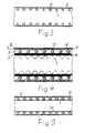
Fig. 1 ein Leitungsrohr nach der Erfindung teilweise im Schnitt. -
Fig. 2 bis 5 ergänzte Ausführungsformen des Leitungsrohrs nachFig. 1 . - In den Zeichnungen sind der Einfachheit halber jeweils nur kurze Abschnitte des Leitungsrohrs nach der Erfindung dargestellt, aus denen die Aufbauelemente desselben hervorgehen.
- Das Leitungsrohr nach
Fig. 1 hat ein Innenrohr 1, das als quer zu seiner Längsrichtung gewelltes Metallrohr ausgeführt ist. Es besteht vorzugsweise aus Edelstahl. Das Innenrohr 1 ist unter Zwischenschaltung einer Trennschicht 2 aus Isoliermaterial von einer ersten radialen Armierung 3 umgeben. Über der ersten radialen Armierung 3 liegt wieder eine Trennschicht 4 aus Isoliermaterial, an welcher als Außenrohr 5 ein quer zu seiner Längsrichtung gewelltes Metallrohr anliegt. Das Außenrohr 5 ist unter Zwischenschaltung einer isolierenden Schicht 6 von zwei, der axialen Stabilisierung des Leitungsrohrs dienenden Lagen aus zugfesten Strängen 7 und 8 umgeben, die mit Vorteil aus Metall, insbesondere aus Stahl, oder aus Aramid bestehen. Über dem Strang 8 der äußeren Lage ist eine Schicht 9 aus Isoliermaterial angebracht. Zwischen den beiden Strängen 7 und 8 liegt mit Vorteil eine aus Isoliermaterial bestehende Trennschicht. Die beiden Stränge 7 und 8 sind vorzugsweise mit gegenläufiger Schlagrichtung um ihre jeweilige Unterlage herumgewickelt. Es können auch mehr als zwei zugfeste Stränge über dem Außenrohr 5 aufgebracht sein. - Zur weiteren radialen Stabilisierung sowie zur Verbesserung der thermischen Isoliereigenschaft des Leitungsrohrs kann gemäß
Fig. 2 um die erste radiale Armierung 3 herum, konzentrisch zu derselben eine zweite radiale Armierung 10 angebracht sein, die von der ersten radialen Armierung 3 durch eine nur schematisch angedeutete Abstandshalterung 11 getrennt ist. - Gemäß
Fig. 3 kann das Innenrohr 1 zusätzlich durch einen Profilkörper 12 abgestützt sein, der an der aus Isoliermaterial bestehenden Schicht 2 anliegt und in die Wellentäler des Innenrohrs 1 mit Anlage an demselben hineinragt. Der Profilkörper 12 besteht mit Vorteil aus einem druck- und zugfesten Material, wie einem faserverstärkten Kunststoff oder Metall. Er soll gegenüber dem metallischen Innenrohr 1 gute Gleiteigenschaften haben. Bei einem wendelförmig gewellten Innenrohr 1 wird nur ein Profilkörper 12 eingesetzt, der dann als Wendel ausgeführt ist. Bei einem ringförmig gewellten Innenrohr 1 ist für jedes Wellental desselben ein einzelner Profilkörper erforderlich, so daß der Profilkörper 12 dann aus einer Vielzahl von Profilkörpern besteht. Bei dieser Ausführungsform des Leitungsrohrs kann es zweckmäßig sein, wenn beispielsweise nur in jedem zweiten oder dritten Wellental ein solcher Profilkörper angeordnet wird. - Entsprechend der Ausführungsform des Leitungsrohrs nach
Fig. 4 kann auch das Außenrohr 5 zusätzlich durch einen Profilkörper 13 abgestützt sein, der in gleicher Weise wie der Profilkörper 12 ausgeführt sein kann. Er liegt an der Schicht 6 aus Isoliermaterial an und ragt in die Wellentäler des Außenrohrs 5 unter Anlage an demselben hinein. - Im Innenrohr 1 kann gemäß
Fig. 5 auch ein dasselbe auskleidender Schlauch 14 aus Isoliermaterial angeordnet sein, der auch als "Liner" bezeichnet wird. Zum - Druckausgleich mit dem zwischen Innenrohr 1 und Schlauch 14 liegenden Hohlraum kann der Schlauch 14 auf seiner ganzen Länge durch Anbringung von Löchern perforiert sein.
Claims (6)
- Leitungsrohr zum Unterwasser-Transport eines Fluids, welches ein das Fluid führendes, druckfestes metallisches Innenrohr aufweist, um das herum zu seiner Stabilisierung in radialer Richtung mindestens ein profilierter, metallischer Strang und zur Stabilisierung in axialer Richtung mindestens ein zugfester Strang herumgewickelt sind, wobei zwischen den einzelnen Lagen aus metallischen Elementen jeweils eine Zwischenschicht aus Isoliermaterial angebracht ist, dadurch gekennzeichnet,- daß das Innenrohr (1) ein quer zu seiner Längsrichtung gewelltes Metallrohr ist,- daß das Innenrohr (1) zur Stabilisierung in radialer Richtung von mindestens einer ersten radialen Armierung (3) umgeben ist, die aus einem profilierten, wendelförmig verlaufenden Profilstreifen besteht, dessen Windungen eng aneinander liegen oder ineinander greifen und miteinander verhakt sind,- daß um die erste radiale Armierung (3) herum ein quer zu seiner Längsrichtung gewelltes Metallrohr als Außenrohr (5) angebracht ist und- daß um das Außenrohr (5) mindestens zwei Lagen aus zugfesten Strängen (7,8) herumgewickelt sind, vorzugsweise mit entgegengesetzter Schlagrichtung.
- Leitungsrohr nach Anspruch 1, dadurch gekennzeichnet, daß die erste radiale Armierung (3) unter Zwischenschaltung einer Abstandshalterung (11) von einer zweiten radialen Armierung (10) umgeben ist.
- Leitungsrohr nach Anspruch 1 oder 2, dadurch gekennzeichnet, daß in dem Innenrohr (1) ein dasselbe auskleidender Schlauch (14) aus Isoliermaterial angebracht ist.
- Leitungsrohr nach Anspruch 3, dadurch gekennzeichnet, daß der Schlauch (14) auf seiner ganzen Länge perforiert ist.
- Leitungsrohr nach Anspruch 1, dadurch gekennzeichnet, daß die zugfesten Stränge (7,8) zwischen Schichten aus Isoliermaterial eingebettet sind.
- Leitungsrohr nach Anspruch 1, dadurch gekennzeichnet, daß von außen in die Wellung von Innenrohr (1) und/oder Außenrohr (5) eingreifende, der Abstützung dienende Profilkörper (12,13) vorhanden sind.
Priority Applications (6)
| Application Number | Priority Date | Filing Date | Title |
|---|---|---|---|
| DK10305803T DK2410223T3 (da) | 2010-07-21 | 2010-07-21 | Ledning til transport af et medium under vand |
| EP20100305803 EP2410223B1 (de) | 2010-07-21 | 2010-07-21 | Leitungsrohr zum Unterwasser-Transport eines Fluids |
| US13/107,292 US9027606B2 (en) | 2010-07-21 | 2011-05-13 | Underwater conduit for fluid transport |
| CA2744809A CA2744809A1 (en) | 2010-07-21 | 2011-06-22 | Pipe for underwater transportation of liquids |
| AU2011203076A AU2011203076A1 (en) | 2010-07-21 | 2011-06-23 | Pipe for Underwater Transportation of Liquids |
| BRPI1103533 BRPI1103533A2 (pt) | 2010-07-21 | 2011-07-20 | tubulação para o transporte submerso de um fluido |
Applications Claiming Priority (1)
| Application Number | Priority Date | Filing Date | Title |
|---|---|---|---|
| EP20100305803 EP2410223B1 (de) | 2010-07-21 | 2010-07-21 | Leitungsrohr zum Unterwasser-Transport eines Fluids |
Publications (2)
| Publication Number | Publication Date |
|---|---|
| EP2410223A1 true EP2410223A1 (de) | 2012-01-25 |
| EP2410223B1 EP2410223B1 (de) | 2013-07-03 |
Family
ID=43303792
Family Applications (1)
| Application Number | Title | Priority Date | Filing Date |
|---|---|---|---|
| EP20100305803 Not-in-force EP2410223B1 (de) | 2010-07-21 | 2010-07-21 | Leitungsrohr zum Unterwasser-Transport eines Fluids |
Country Status (6)
| Country | Link |
|---|---|
| US (1) | US9027606B2 (de) |
| EP (1) | EP2410223B1 (de) |
| AU (1) | AU2011203076A1 (de) |
| BR (1) | BRPI1103533A2 (de) |
| CA (1) | CA2744809A1 (de) |
| DK (1) | DK2410223T3 (de) |
Cited By (2)
| Publication number | Priority date | Publication date | Assignee | Title |
|---|---|---|---|---|
| EP2873901A1 (de) * | 2013-11-15 | 2015-05-20 | Nexans | Flexible Rohrleitung |
| EP3333562A3 (de) * | 2016-12-09 | 2018-09-05 | Nexans | Fernerkennung von isolierungsschäden an isolierten röhren oder rohren |
Families Citing this family (1)
| Publication number | Priority date | Publication date | Assignee | Title |
|---|---|---|---|---|
| CN106369231A (zh) * | 2016-11-18 | 2017-02-01 | 安徽瑞通塑业有限公司 | 一种双层高强度变径波纹管 |
Citations (3)
| Publication number | Priority date | Publication date | Assignee | Title |
|---|---|---|---|---|
| GB2051297A (en) * | 1979-05-30 | 1981-01-14 | Coflexip | Flexible pipeline |
| US4984605A (en) * | 1988-02-03 | 1991-01-15 | Kabelmetal Electro | Conducting tube |
| US6053213A (en) * | 1998-02-18 | 2000-04-25 | Coflexip | Flexible pipe for great depths |
Family Cites Families (23)
| Publication number | Priority date | Publication date | Assignee | Title |
|---|---|---|---|---|
| US3165123A (en) * | 1961-04-03 | 1965-01-12 | Phillips Petroleum Co | Control of pressure drop in fluid flow |
| US6065501A (en) * | 1989-06-30 | 2000-05-23 | Institute Francais Du Petrole | Flexible tube having at least one elongated reinforcing element with a T-shaped profile |
| US5256233A (en) * | 1989-09-11 | 1993-10-26 | Dayco Products, Inc. | Flexible hose construction and method of making the same |
| US5645109A (en) * | 1990-06-29 | 1997-07-08 | Coflexip | Flexible tubular pipe comprising an interlocked armoring web and process for producing it |
| US5485870A (en) * | 1994-12-05 | 1996-01-23 | Kraik; Newell P. | Wire wrapped composite spiral hose and method |
| US5778940A (en) * | 1996-06-11 | 1998-07-14 | Hbd Industries, Inc. | Combination rubber/composite hose |
| FR2782141B1 (fr) * | 1998-08-10 | 2000-09-08 | Coflexip | Conduite flexible resistante a fluage limite de la gaine d'etancheite |
| FR2784445B1 (fr) * | 1998-10-12 | 2000-11-17 | Coflexip | Conduite flexible a frette de forte inertie |
| EP1141606B1 (de) * | 1998-12-16 | 2004-03-10 | NKT Flexibles I/S | Armiertes, flexibles rohr und seine anwendung |
| KR20030082578A (ko) * | 2001-01-30 | 2003-10-22 | 파커-한니핀 코포레이션 | 열가소성 보강 호스 구조물 및 그의 제조 방법 |
| BR0209395B1 (pt) * | 2001-05-04 | 2011-02-22 | tubulação flexìvel reforçada, e, uso da mesma. | |
| CA2452947A1 (en) * | 2001-07-07 | 2003-01-23 | Uponor Innovation Ab | Insulated heating and/or sanitation pipe |
| FR2828924B1 (fr) * | 2001-08-27 | 2003-10-31 | Coflexip | Conduite flexible pour le transport d'un fluide |
| JP4213910B2 (ja) * | 2002-05-24 | 2009-01-28 | 株式会社ブリヂストン | 給水給湯用ホース |
| JP4168691B2 (ja) * | 2002-07-30 | 2008-10-22 | 東海ゴム工業株式会社 | 蛇腹金属管付ホース |
| US6983769B2 (en) * | 2003-06-23 | 2006-01-10 | Tokai Rubber Industries, Ltd. | Vibration absorbing hose |
| US7123826B2 (en) * | 2003-07-16 | 2006-10-17 | Wellstream International Ltd. | Temperature controlled pipe and method of manufacturing same |
| FR2861158B1 (fr) * | 2003-10-17 | 2006-01-27 | Technip France | Conduite tubulaire flexible notamment pour exploitation petroliere, a enroulement de ptfe. |
| BRPI0710425A8 (pt) * | 2006-05-08 | 2019-01-15 | Bhp Billiton Petroleum Pty Ltd | mangueira, uso de uma mangueira , método para fabricar mangueira e aparelho para fabricar mangueira |
| GB0616053D0 (en) * | 2006-08-11 | 2006-09-20 | Bhp Billiton Petroleum Pty Ltd | Improvements relating to hose |
| US7781040B2 (en) * | 2007-03-21 | 2010-08-24 | Deepflex Inc. | Flexible composite tubular assembly with high insulation properties and method for making same |
| US7946313B2 (en) * | 2008-03-05 | 2011-05-24 | Vo Dang The | Flexible pipe |
| JP5184177B2 (ja) * | 2008-03-28 | 2013-04-17 | 古河電気工業株式会社 | 極低温流体輸送用可撓管 |
-
2010
- 2010-07-21 EP EP20100305803 patent/EP2410223B1/de not_active Not-in-force
- 2010-07-21 DK DK10305803T patent/DK2410223T3/da active
-
2011
- 2011-05-13 US US13/107,292 patent/US9027606B2/en not_active Expired - Fee Related
- 2011-06-22 CA CA2744809A patent/CA2744809A1/en not_active Abandoned
- 2011-06-23 AU AU2011203076A patent/AU2011203076A1/en not_active Abandoned
- 2011-07-20 BR BRPI1103533 patent/BRPI1103533A2/pt not_active Application Discontinuation
Patent Citations (3)
| Publication number | Priority date | Publication date | Assignee | Title |
|---|---|---|---|---|
| GB2051297A (en) * | 1979-05-30 | 1981-01-14 | Coflexip | Flexible pipeline |
| US4984605A (en) * | 1988-02-03 | 1991-01-15 | Kabelmetal Electro | Conducting tube |
| US6053213A (en) * | 1998-02-18 | 2000-04-25 | Coflexip | Flexible pipe for great depths |
Cited By (3)
| Publication number | Priority date | Publication date | Assignee | Title |
|---|---|---|---|---|
| EP2873901A1 (de) * | 2013-11-15 | 2015-05-20 | Nexans | Flexible Rohrleitung |
| CN104653903A (zh) * | 2013-11-15 | 2015-05-27 | 尼克桑斯公司 | 柔性导管 |
| EP3333562A3 (de) * | 2016-12-09 | 2018-09-05 | Nexans | Fernerkennung von isolierungsschäden an isolierten röhren oder rohren |
Also Published As
| Publication number | Publication date |
|---|---|
| US20120018027A1 (en) | 2012-01-26 |
| US9027606B2 (en) | 2015-05-12 |
| AU2011203076A1 (en) | 2012-02-09 |
| DK2410223T3 (da) | 2013-08-26 |
| CA2744809A1 (en) | 2012-01-21 |
| BRPI1103533A2 (pt) | 2012-12-11 |
| EP2410223B1 (de) | 2013-07-03 |
Similar Documents
| Publication | Publication Date | Title |
|---|---|---|
| DE69006191T2 (de) | Flexible Rohrleitung. | |
| DE2361162C2 (de) | Flexible Leitung | |
| DE60116759T2 (de) | Schlauch | |
| DE3229257C2 (de) | Elektrisches Flachkabel | |
| DE69223059T2 (de) | Wendelförmig gewickelte rippenverstärkte verbundstruktur | |
| DE3513858A1 (de) | Unterwasser-nachrichtenuebertragungskabel mit optischen fasern | |
| DE1901069A1 (de) | Koaxiale Mehrfachrohranordnung | |
| DE3019335A1 (de) | Flexible rohrleitung | |
| DE2905894A1 (de) | Flexibles zellenrohr | |
| DE3513859A1 (de) | Unterwasser-nachrichtenuebertragungskabel mit einer mehrzahl von optischen fasern | |
| EP2146125A1 (de) | Flexibles Leitungsrohr | |
| EP3007179A1 (de) | Kabel hoher steifigkeit und verfahren zu seiner herstellung | |
| WO2018138250A1 (de) | Längselement, insbesondere für ein zug- oder tragmittel | |
| EP2410223B1 (de) | Leitungsrohr zum Unterwasser-Transport eines Fluids | |
| EP2284428A1 (de) | Leitungsrohr und Verfahren zu seiner Herstellung | |
| DE1957168A1 (de) | Flexibler Schlauch | |
| DE2913519C3 (de) | Flexible Rohrleitung | |
| DE3322103A1 (de) | Kabel | |
| DE69107076T2 (de) | Transport von flüssigkeiten. | |
| DE3221333A1 (de) | Wellschlauch mit kunststoff-auskleidung | |
| DE3335368A1 (de) | Kabel, insbesondere zur verwendung bei erdoelbohrungen | |
| EP2226543A2 (de) | Kunststoffrohr mit strukturierter Außenschicht | |
| DE10021523C2 (de) | Rohr | |
| EP0436772A2 (de) | Leitungselement in Form eines Wellschlauches oder Balges | |
| EP2733707B1 (de) | Langgestrecktes Gut mit einer Armierung |
Legal Events
| Date | Code | Title | Description |
|---|---|---|---|
| 17P | Request for examination filed |
Effective date: 20110103 |
|
| AK | Designated contracting states |
Kind code of ref document: A1 Designated state(s): AL AT BE BG CH CY CZ DE DK EE ES FI FR GB GR HR HU IE IS IT LI LT LU LV MC MK MT NL NO PL PT RO SE SI SK SM TR |
|
| AX | Request for extension of the european patent |
Extension state: BA ME RS |
|
| PUAI | Public reference made under article 153(3) epc to a published international application that has entered the european phase |
Free format text: ORIGINAL CODE: 0009012 |
|
| RIC1 | Information provided on ipc code assigned before grant |
Ipc: F16L 11/16 20060101ALI20121220BHEP Ipc: F16L 59/153 20060101ALI20121220BHEP Ipc: F16L 11/08 20060101AFI20121220BHEP |
|
| GRAP | Despatch of communication of intention to grant a patent |
Free format text: ORIGINAL CODE: EPIDOSNIGR1 |
|
| GRAS | Grant fee paid |
Free format text: ORIGINAL CODE: EPIDOSNIGR3 |
|
| GRAA | (expected) grant |
Free format text: ORIGINAL CODE: 0009210 |
|
| AK | Designated contracting states |
Kind code of ref document: B1 Designated state(s): AL AT BE BG CH CY CZ DE DK EE ES FI FR GB GR HR HU IE IS IT LI LT LU LV MC MK MT NL NO PL PT RO SE SI SK SM TR |
|
| REG | Reference to a national code |
Ref country code: GB Ref legal event code: FG4D Free format text: NOT ENGLISH |
|
| REG | Reference to a national code |
Ref country code: CH Ref legal event code: EP Ref country code: AT Ref legal event code: REF Ref document number: 619982 Country of ref document: AT Kind code of ref document: T Effective date: 20130715 |
|
| REG | Reference to a national code |
Ref country code: IE Ref legal event code: FG4D Free format text: LANGUAGE OF EP DOCUMENT: GERMAN |
|
| REG | Reference to a national code |
Ref country code: DK Ref legal event code: T3 |
|
| REG | Reference to a national code |
Ref country code: DE Ref legal event code: R096 Ref document number: 502010003865 Country of ref document: DE Effective date: 20130829 |
|
| REG | Reference to a national code |
Ref country code: NO Ref legal event code: T2 Effective date: 20130703 |
|
| PG25 | Lapsed in a contracting state [announced via postgrant information from national office to epo] |
Ref country code: SI Free format text: LAPSE BECAUSE OF FAILURE TO SUBMIT A TRANSLATION OF THE DESCRIPTION OR TO PAY THE FEE WITHIN THE PRESCRIBED TIME-LIMIT Effective date: 20130703 |
|
| REG | Reference to a national code |
Ref country code: NL Ref legal event code: VDEP Effective date: 20130703 |
|
| REG | Reference to a national code |
Ref country code: LT Ref legal event code: MG4D |
|
| BERE | Be: lapsed |
Owner name: NEXANS Effective date: 20130731 |
|
| PG25 | Lapsed in a contracting state [announced via postgrant information from national office to epo] |
Ref country code: LT Free format text: LAPSE BECAUSE OF FAILURE TO SUBMIT A TRANSLATION OF THE DESCRIPTION OR TO PAY THE FEE WITHIN THE PRESCRIBED TIME-LIMIT Effective date: 20130703 Ref country code: CY Free format text: LAPSE BECAUSE OF FAILURE TO SUBMIT A TRANSLATION OF THE DESCRIPTION OR TO PAY THE FEE WITHIN THE PRESCRIBED TIME-LIMIT Effective date: 20130807 Ref country code: PT Free format text: LAPSE BECAUSE OF FAILURE TO SUBMIT A TRANSLATION OF THE DESCRIPTION OR TO PAY THE FEE WITHIN THE PRESCRIBED TIME-LIMIT Effective date: 20131104 Ref country code: SE Free format text: LAPSE BECAUSE OF FAILURE TO SUBMIT A TRANSLATION OF THE DESCRIPTION OR TO PAY THE FEE WITHIN THE PRESCRIBED TIME-LIMIT Effective date: 20130703 Ref country code: IS Free format text: LAPSE BECAUSE OF FAILURE TO SUBMIT A TRANSLATION OF THE DESCRIPTION OR TO PAY THE FEE WITHIN THE PRESCRIBED TIME-LIMIT Effective date: 20131103 Ref country code: HR Free format text: LAPSE BECAUSE OF FAILURE TO SUBMIT A TRANSLATION OF THE DESCRIPTION OR TO PAY THE FEE WITHIN THE PRESCRIBED TIME-LIMIT Effective date: 20130703 |
|
| PG25 | Lapsed in a contracting state [announced via postgrant information from national office to epo] |
Ref country code: GR Free format text: LAPSE BECAUSE OF FAILURE TO SUBMIT A TRANSLATION OF THE DESCRIPTION OR TO PAY THE FEE WITHIN THE PRESCRIBED TIME-LIMIT Effective date: 20131004 Ref country code: FI Free format text: LAPSE BECAUSE OF FAILURE TO SUBMIT A TRANSLATION OF THE DESCRIPTION OR TO PAY THE FEE WITHIN THE PRESCRIBED TIME-LIMIT Effective date: 20130703 Ref country code: PL Free format text: LAPSE BECAUSE OF FAILURE TO SUBMIT A TRANSLATION OF THE DESCRIPTION OR TO PAY THE FEE WITHIN THE PRESCRIBED TIME-LIMIT Effective date: 20130703 Ref country code: LV Free format text: LAPSE BECAUSE OF FAILURE TO SUBMIT A TRANSLATION OF THE DESCRIPTION OR TO PAY THE FEE WITHIN THE PRESCRIBED TIME-LIMIT Effective date: 20130703 Ref country code: ES Free format text: LAPSE BECAUSE OF FAILURE TO SUBMIT A TRANSLATION OF THE DESCRIPTION OR TO PAY THE FEE WITHIN THE PRESCRIBED TIME-LIMIT Effective date: 20131014 Ref country code: NL Free format text: LAPSE BECAUSE OF FAILURE TO SUBMIT A TRANSLATION OF THE DESCRIPTION OR TO PAY THE FEE WITHIN THE PRESCRIBED TIME-LIMIT Effective date: 20130703 |
|
| PG25 | Lapsed in a contracting state [announced via postgrant information from national office to epo] |
Ref country code: CY Free format text: LAPSE BECAUSE OF FAILURE TO SUBMIT A TRANSLATION OF THE DESCRIPTION OR TO PAY THE FEE WITHIN THE PRESCRIBED TIME-LIMIT Effective date: 20130703 |
|
| REG | Reference to a national code |
Ref country code: IE Ref legal event code: MM4A |
|
| PG25 | Lapsed in a contracting state [announced via postgrant information from national office to epo] |
Ref country code: EE Free format text: LAPSE BECAUSE OF FAILURE TO SUBMIT A TRANSLATION OF THE DESCRIPTION OR TO PAY THE FEE WITHIN THE PRESCRIBED TIME-LIMIT Effective date: 20130703 Ref country code: MC Free format text: LAPSE BECAUSE OF FAILURE TO SUBMIT A TRANSLATION OF THE DESCRIPTION OR TO PAY THE FEE WITHIN THE PRESCRIBED TIME-LIMIT Effective date: 20130703 Ref country code: RO Free format text: LAPSE BECAUSE OF FAILURE TO SUBMIT A TRANSLATION OF THE DESCRIPTION OR TO PAY THE FEE WITHIN THE PRESCRIBED TIME-LIMIT Effective date: 20130703 Ref country code: BE Free format text: LAPSE BECAUSE OF NON-PAYMENT OF DUE FEES Effective date: 20130731 Ref country code: CZ Free format text: LAPSE BECAUSE OF FAILURE TO SUBMIT A TRANSLATION OF THE DESCRIPTION OR TO PAY THE FEE WITHIN THE PRESCRIBED TIME-LIMIT Effective date: 20130703 Ref country code: SK Free format text: LAPSE BECAUSE OF FAILURE TO SUBMIT A TRANSLATION OF THE DESCRIPTION OR TO PAY THE FEE WITHIN THE PRESCRIBED TIME-LIMIT Effective date: 20130703 |
|
| PLBE | No opposition filed within time limit |
Free format text: ORIGINAL CODE: 0009261 |
|
| STAA | Information on the status of an ep patent application or granted ep patent |
Free format text: STATUS: NO OPPOSITION FILED WITHIN TIME LIMIT |
|
| PG25 | Lapsed in a contracting state [announced via postgrant information from national office to epo] |
Ref country code: IT Free format text: LAPSE BECAUSE OF FAILURE TO SUBMIT A TRANSLATION OF THE DESCRIPTION OR TO PAY THE FEE WITHIN THE PRESCRIBED TIME-LIMIT Effective date: 20130703 |
|
| 26N | No opposition filed |
Effective date: 20140404 |
|
| REG | Reference to a national code |
Ref country code: DE Ref legal event code: R097 Ref document number: 502010003865 Country of ref document: DE Effective date: 20140404 |
|
| PG25 | Lapsed in a contracting state [announced via postgrant information from national office to epo] |
Ref country code: IE Free format text: LAPSE BECAUSE OF NON-PAYMENT OF DUE FEES Effective date: 20130721 |
|
| REG | Reference to a national code |
Ref country code: CH Ref legal event code: PL |
|
| PG25 | Lapsed in a contracting state [announced via postgrant information from national office to epo] |
Ref country code: LI Free format text: LAPSE BECAUSE OF NON-PAYMENT OF DUE FEES Effective date: 20140731 Ref country code: CH Free format text: LAPSE BECAUSE OF NON-PAYMENT OF DUE FEES Effective date: 20140731 |
|
| PG25 | Lapsed in a contracting state [announced via postgrant information from national office to epo] |
Ref country code: SM Free format text: LAPSE BECAUSE OF FAILURE TO SUBMIT A TRANSLATION OF THE DESCRIPTION OR TO PAY THE FEE WITHIN THE PRESCRIBED TIME-LIMIT Effective date: 20130703 |
|
| PG25 | Lapsed in a contracting state [announced via postgrant information from national office to epo] |
Ref country code: TR Free format text: LAPSE BECAUSE OF FAILURE TO SUBMIT A TRANSLATION OF THE DESCRIPTION OR TO PAY THE FEE WITHIN THE PRESCRIBED TIME-LIMIT Effective date: 20130703 Ref country code: MT Free format text: LAPSE BECAUSE OF FAILURE TO SUBMIT A TRANSLATION OF THE DESCRIPTION OR TO PAY THE FEE WITHIN THE PRESCRIBED TIME-LIMIT Effective date: 20130703 |
|
| PG25 | Lapsed in a contracting state [announced via postgrant information from national office to epo] |
Ref country code: LU Free format text: LAPSE BECAUSE OF NON-PAYMENT OF DUE FEES Effective date: 20130721 Ref country code: BG Free format text: LAPSE BECAUSE OF FAILURE TO SUBMIT A TRANSLATION OF THE DESCRIPTION OR TO PAY THE FEE WITHIN THE PRESCRIBED TIME-LIMIT Effective date: 20130703 Ref country code: HU Free format text: LAPSE BECAUSE OF FAILURE TO SUBMIT A TRANSLATION OF THE DESCRIPTION OR TO PAY THE FEE WITHIN THE PRESCRIBED TIME-LIMIT; INVALID AB INITIO Effective date: 20100721 Ref country code: MK Free format text: LAPSE BECAUSE OF FAILURE TO SUBMIT A TRANSLATION OF THE DESCRIPTION OR TO PAY THE FEE WITHIN THE PRESCRIBED TIME-LIMIT Effective date: 20130703 |
|
| REG | Reference to a national code |
Ref country code: FR Ref legal event code: PLFP Year of fee payment: 7 |
|
| REG | Reference to a national code |
Ref country code: AT Ref legal event code: MM01 Ref document number: 619982 Country of ref document: AT Kind code of ref document: T Effective date: 20150721 |
|
| PG25 | Lapsed in a contracting state [announced via postgrant information from national office to epo] |
Ref country code: AT Free format text: LAPSE BECAUSE OF NON-PAYMENT OF DUE FEES Effective date: 20150721 |
|
| REG | Reference to a national code |
Ref country code: FR Ref legal event code: PLFP Year of fee payment: 8 |
|
| REG | Reference to a national code |
Ref country code: FR Ref legal event code: PLFP Year of fee payment: 9 |
|
| PG25 | Lapsed in a contracting state [announced via postgrant information from national office to epo] |
Ref country code: AL Free format text: LAPSE BECAUSE OF FAILURE TO SUBMIT A TRANSLATION OF THE DESCRIPTION OR TO PAY THE FEE WITHIN THE PRESCRIBED TIME-LIMIT Effective date: 20130703 |
|
| PGFP | Annual fee paid to national office [announced via postgrant information from national office to epo] |
Ref country code: DK Payment date: 20180723 Year of fee payment: 9 |
|
| REG | Reference to a national code |
Ref country code: DK Ref legal event code: EBP Effective date: 20190731 |
|
| PG25 | Lapsed in a contracting state [announced via postgrant information from national office to epo] |
Ref country code: DK Free format text: LAPSE BECAUSE OF NON-PAYMENT OF DUE FEES Effective date: 20190731 |
|
| PGFP | Annual fee paid to national office [announced via postgrant information from national office to epo] |
Ref country code: NO Payment date: 20220725 Year of fee payment: 13 Ref country code: GB Payment date: 20220720 Year of fee payment: 13 Ref country code: DE Payment date: 20220720 Year of fee payment: 13 |
|
| PGFP | Annual fee paid to national office [announced via postgrant information from national office to epo] |
Ref country code: FR Payment date: 20220720 Year of fee payment: 13 |
|
| REG | Reference to a national code |
Ref country code: DE Ref legal event code: R119 Ref document number: 502010003865 Country of ref document: DE |
|
| REG | Reference to a national code |
Ref country code: NO Ref legal event code: MMEP |
|
| GBPC | Gb: european patent ceased through non-payment of renewal fee |
Effective date: 20230721 |
|
| PG25 | Lapsed in a contracting state [announced via postgrant information from national office to epo] |
Ref country code: DE Free format text: LAPSE BECAUSE OF NON-PAYMENT OF DUE FEES Effective date: 20240201 Ref country code: GB Free format text: LAPSE BECAUSE OF NON-PAYMENT OF DUE FEES Effective date: 20230721 |
|
| PG25 | Lapsed in a contracting state [announced via postgrant information from national office to epo] |
Ref country code: NO Free format text: LAPSE BECAUSE OF NON-PAYMENT OF DUE FEES Effective date: 20230731 Ref country code: FR Free format text: LAPSE BECAUSE OF NON-PAYMENT OF DUE FEES Effective date: 20230731 |