EP2410211A1 - Hydraulic control device for automatic transmission - Google Patents
Hydraulic control device for automatic transmission Download PDFInfo
- Publication number
- EP2410211A1 EP2410211A1 EP10820089A EP10820089A EP2410211A1 EP 2410211 A1 EP2410211 A1 EP 2410211A1 EP 10820089 A EP10820089 A EP 10820089A EP 10820089 A EP10820089 A EP 10820089A EP 2410211 A1 EP2410211 A1 EP 2410211A1
- Authority
- EP
- European Patent Office
- Prior art keywords
- pressure
- spool
- circulation
- oil chamber
- circulation pressure
- Prior art date
- Legal status (The legal status is an assumption and is not a legal conclusion. Google has not performed a legal analysis and makes no representation as to the accuracy of the status listed.)
- Withdrawn
Links
- 230000005540 biological transmission Effects 0.000 title claims description 67
- 230000001105 regulatory effect Effects 0.000 claims abstract description 13
- 230000008859 change Effects 0.000 claims description 19
- 230000007246 mechanism Effects 0.000 claims description 19
- 239000012530 fluid Substances 0.000 claims description 5
- 238000007599 discharging Methods 0.000 claims description 4
- GAAKALASJNGQKD-UHFFFAOYSA-N LY-165163 Chemical compound C1=CC(N)=CC=C1CCN1CCN(C=2C=C(C=CC=2)C(F)(F)F)CC1 GAAKALASJNGQKD-UHFFFAOYSA-N 0.000 claims 2
- 230000000694 effects Effects 0.000 description 5
- 238000010586 diagram Methods 0.000 description 4
- 239000002783 friction material Substances 0.000 description 4
- 238000007789 sealing Methods 0.000 description 4
- 230000007423 decrease Effects 0.000 description 3
- 238000006073 displacement reaction Methods 0.000 description 3
- 230000009471 action Effects 0.000 description 1
- 238000002485 combustion reaction Methods 0.000 description 1
- 230000006872 improvement Effects 0.000 description 1
- 238000004519 manufacturing process Methods 0.000 description 1
- 230000035939 shock Effects 0.000 description 1
- 238000003756 stirring Methods 0.000 description 1
Images




Classifications
-
- F—MECHANICAL ENGINEERING; LIGHTING; HEATING; WEAPONS; BLASTING
- F16—ENGINEERING ELEMENTS AND UNITS; GENERAL MEASURES FOR PRODUCING AND MAINTAINING EFFECTIVE FUNCTIONING OF MACHINES OR INSTALLATIONS; THERMAL INSULATION IN GENERAL
- F16H—GEARING
- F16H61/00—Control functions within control units of change-speed- or reversing-gearings for conveying rotary motion ; Control of exclusively fluid gearing, friction gearing, gearings with endless flexible members or other particular types of gearing
- F16H61/14—Control of torque converter lock-up clutches
-
- F—MECHANICAL ENGINEERING; LIGHTING; HEATING; WEAPONS; BLASTING
- F16—ENGINEERING ELEMENTS AND UNITS; GENERAL MEASURES FOR PRODUCING AND MAINTAINING EFFECTIVE FUNCTIONING OF MACHINES OR INSTALLATIONS; THERMAL INSULATION IN GENERAL
- F16H—GEARING
- F16H61/00—Control functions within control units of change-speed- or reversing-gearings for conveying rotary motion ; Control of exclusively fluid gearing, friction gearing, gearings with endless flexible members or other particular types of gearing
- F16H61/14—Control of torque converter lock-up clutches
- F16H61/143—Control of torque converter lock-up clutches using electric control means
-
- F—MECHANICAL ENGINEERING; LIGHTING; HEATING; WEAPONS; BLASTING
- F16—ENGINEERING ELEMENTS AND UNITS; GENERAL MEASURES FOR PRODUCING AND MAINTAINING EFFECTIVE FUNCTIONING OF MACHINES OR INSTALLATIONS; THERMAL INSULATION IN GENERAL
- F16K—VALVES; TAPS; COCKS; ACTUATING-FLOATS; DEVICES FOR VENTING OR AERATING
- F16K11/00—Multiple-way valves, e.g. mixing valves; Pipe fittings incorporating such valves
- F16K11/02—Multiple-way valves, e.g. mixing valves; Pipe fittings incorporating such valves with all movable sealing faces moving as one unit
- F16K11/06—Multiple-way valves, e.g. mixing valves; Pipe fittings incorporating such valves with all movable sealing faces moving as one unit comprising only sliding valves, i.e. sliding closure elements
- F16K11/065—Multiple-way valves, e.g. mixing valves; Pipe fittings incorporating such valves with all movable sealing faces moving as one unit comprising only sliding valves, i.e. sliding closure elements with linearly sliding closure members
- F16K11/07—Multiple-way valves, e.g. mixing valves; Pipe fittings incorporating such valves with all movable sealing faces moving as one unit comprising only sliding valves, i.e. sliding closure elements with linearly sliding closure members with cylindrical slides
-
- F—MECHANICAL ENGINEERING; LIGHTING; HEATING; WEAPONS; BLASTING
- F16—ENGINEERING ELEMENTS AND UNITS; GENERAL MEASURES FOR PRODUCING AND MAINTAINING EFFECTIVE FUNCTIONING OF MACHINES OR INSTALLATIONS; THERMAL INSULATION IN GENERAL
- F16K—VALVES; TAPS; COCKS; ACTUATING-FLOATS; DEVICES FOR VENTING OR AERATING
- F16K31/00—Actuating devices; Operating means; Releasing devices
- F16K31/02—Actuating devices; Operating means; Releasing devices electric; magnetic
- F16K31/06—Actuating devices; Operating means; Releasing devices electric; magnetic using a magnet, e.g. diaphragm valves, cutting off by means of a liquid
Definitions
- the present invention relates to a hydraulic control device of an automatic transmission that is mounted on, e.g., a vehicle, and more particularly to a hydraulic control device of an automatic transmission which regulates a working pressure that engages and disengages a clutch by the difference from a circulation pressure of a starting device, by using a pressure-regulating solenoid valve.
- an automatic transmission mounted on, e.g., a vehicle has been becoming common including a hydraulic power transmission device such as a torque converter, and also including a lockup clutch for locking up the hydraulic power transmission device in order to reduce transmission loss in the hydraulic power transmission device.
- Engagement/disengagement control and slip control of this lockup clutch are performed based on the difference between a circulation pressure P CIR of oil that circulates as a working fluid of the hydraulic power transmission device (an on-pressure P ON that acts on the engaging side), and a working pressure P APP that is electronically controlled (an off-pressure P OFF that acts on the disengaging side).
- the working pressure P APP is generated by a control valve that is controlled by an output pressure of a linear solenoid valve that uses, e.g., a modulator pressure, namely a line pressure controlled to a constant pressure (alternatively, the line pressure or a secondary pressure) as a source pressure.
- a modulator pressure namely a line pressure controlled to a constant pressure (alternatively, the line pressure or a secondary pressure) as a source pressure.
- Patent Document 1 Japanese Patent Application Publication No. JP-A-2006-242347
- the circulation pressure P CIR is input as a feedback pressure to an oil chamber (120) provided in the linear solenoid valve, and the working pressure P APP that is output is input as a feedback pressure to an oil chamber (122) provided on the opposite side via a spool (114).
- a linear solenoid valve 110 is formed by a solenoid portion 111 and a valve portion 112, and a protruding portion on which a plunger 111 d driven by a coil 111a abuts needs be formed in a spool 112p of the valve portion 112. That is, a pressure-receiving area of an oil chamber 112a is a pressure receiving area obtained by subtracting an area A2 of the protruding portion from a pressure-receiving area A1 of the oil chamber 112b (A1 - A2).
- ⁇ P APP A ⁇ 1 - A ⁇ 2 / A ⁇ 1 • ⁇ P CIR
- the circulation pressure P CIR varies so as to first increase and then decrease rapidly.
- the working pressure P APP that is output from the linear solenoid valve 110 is "(A1 - A2)/A1 ⁇ 1”
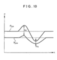
- the working pressure P APP varies less than the circulation pressure P CIR , based on the above expression (1), whereby the difference Pd between the circulation pressure P CIR and the working pressure P APP may increase and decrease.
- the linear solenoid valve 110 described in Patent Document 1 may not be able to maintain the differential pressure Pd at an intended value when the circulation pressure varies.
- a device is proposed without the hydraulic power transmission device such as the torque converter, which enables starting of the vehicle while slip-controlling a starting clutch.
- the circulation pressure of the starting clutch varies upon such starting of the vehicle as described above, and thus the differential pressure of the starting clutch may not be maintained at an intended value, which may cause shocks or vibrations upon starting of the vehicle.
- a hydraulic control device (1 1 , 1 2 , 1 3 ) of an automatic transmission (AT) includes: a circulation pressure supply portion (6, 7 in FIG. 1 ; 6 , 17 in FIG. 5 ; and 6 , 9 , 27 in FIG.
- a circulation pressure (P CIR ) for supplying a circulation pressure (P CIR ) to a starting device (2, 22, 32) having a clutch (3, 23, 33) capable of enabling and disabling power transmission between a driving source (EG) and an automatic speed change mechanism (40); and a pressure-regulating solenoid valve (10 1 to 10 5 ) capable of regulating a working pressure (P APP ) that engages and disengages the clutch (3, 23, 33) by a difference from the circulation pressure (P CIR ), wherein the pressure-regulating solenoid valve (10 1 to 10 5 ) has a solenoid portion (11) that is driven electrically, and a spool portion (12 1 to 12 5 ) including a spool (12p) that is drivingly pressed by the solenoid portion (11) .
- the hydraulic control device (1 1 , 1 2 , 1 3 ) is characterized in that the spool portion (12 1 to 12 5 ) includes a first feedback oil chamber (12b) for feeding back the working pressure (P APP ) to the spool (12p), and a second feedback oil chamber (12a) for feeding back the circulation pressure (P CIR ) to the spool (12p) in a direction opposite to the first feedback oil chamber (12b), and a pressure-receiving area (A1 - A2) of the first feedback oil chamber (12b) and a pressure-receiving area (A1 - A2) of the second feedback oil chamber (12a) are set equal to each other in the spool (12p).
- the present invention (see, e.g., FIGS. 1 and 5 ) is characterized in that the starting device (2, 22) includes a hydraulic power transmission device (4) for performing the power transmission between the driving source (EG) and the automatic speed change mechanism (40) via a fluid, and the clutch is a lockup clutch (3, 23).
- the present invention is characterized by further including: a circulation pressure supply oil passage (c4) for supplying the circulation pressure (P CIR ) from the circulation pressure supply portion (6, 17 in FIG. 5 ; and 6 , 9 , 27 in FIG.
- a circulation pressure discharge oil passage (d1) for discharging the circulation pressure (P CIR ) in the starting device (22, 32) from a circulation pressure discharge port (22e, 32e) of the starting device (2, 22); a working pressure supply oil passage (e3) for supplying the working pressure (P APP ) from the pressure-regulating solenoid valve (10) to a working pressure supply port (22c, 32c) of the starting device (22, 32); and a circulation pressure introducing oil passage (c5) for introducing the circulation pressure (P CIR ) into the second feedback oil chamber (12a) from one (e.g., 22d, 32d) of the circulation pressure supply port (22d, 32d) and the circulation pressure discharge port (22e, 32e) that is located closer to the clutch (22, 32).
- the present invention (see, e.g., FIGS. 7 and 8 ) is characterized in that the spool portion (12 4 , 12 5 ) of the pressure-regulating solenoid valve (10 4 , 10 5 ) has a main sleeve (12SA) that entirely contains the spool (12p) and slidably supports at least one end of the spool (12p), and a sub sleeve (12SB) that is interposed between the main sleeve (12SA) and the other end of the spool (12p) and slidably supports the other end of the spool (12p), and the spool is separated and formed into a first spool (12p 1 ) that is slidably supported by the main sleeve (12SA), and a second spool (12p 2 ) that is slidably supported by the sub sleeve (12SB).
- the spool portion (12 4 , 12 5 ) of the pressure-regulating solenoid valve (10 4 , 10 5 )
- the pressure-receiving area of the first feedback oil chamber and the pressure-receiving area of the second feedback oil chamber are set equal to each other in the spool.
- the oil pressure acting force of the working pressure of the first feedback oil chamber and that of the circulation pressure of the second feedback oil chamber can be equal to each other, whereby engagement/disengagement control and slip control of the clutch can be accurately performed.
- the starting device includes the hydraulic power transmission device for performing the power transmission between the driving source and the automatic speed change mechanism via a fluid
- the clutch is a lockup clutch.
- the circulation pressure is introduced into the second feedback oil chamber from one of the circulation pressure supply port and the circulation pressure discharge port that is located closer to the clutch.
- the spool is separated and formed into the first spool that is slidably supported by the main sleeve, and the second spool that is slidably supported by the sub sleeve.
- FIGS. 1 to 4 A first embodiment of the present invention will be described below with reference to FIGS. 1 to 4 .
- an automatic transmission AT is connected to an engine (a driving source) EG, and mainly includes a starting device 2, an automatic speed change mechanism 40, and a hydraulic control device 1.
- the starting device 2 has a torque converter 4 and a lockup clutch 3.
- the torque converter (a hydraulic power transmission device) 4 includes: a pump impeller 4a coupled to a front cover 2A to which rotation from the engine EG is input; a turbine runner 4b which is positioned to face the pump impeller 4a so that power is hydraulically transmitted to the turbine runner 4b via oil, and which is connected to an input shaft 40a of the automatic speed change mechanism 40; and a stator 4c which is positioned between the pump impeller 4a and the turbine runner 4b, and whose rotation is restricted to one direction by a one-way clutch 4d.
- the lockup clutch (a clutch) 3 includes a piston 3a positioned so as to be movable in the axial direction, and a friction material 3b provided on the outer periphery of the piston 3a.
- the piston 3a is placed so as to separate an oil-tight space 2a from an oil-tight space 2b, and is drivingly moved to and away from the front cover 2A by the differential pressure between the space 2a and the space 2b. That is, as the oil pressure in the space 2b increases, the friction material 3b is separated from the inner side surface of the front cover 2A, and is disengagement-controlled.
- the friction material 3b is pressed against the inner side surface of the front cover 2A, and is slip-controlled and engagement-controlled, whereby the lockup clutch 3 is engaged.
- the front cover 2A is directly engaged with the input shaft of the automatic speed change mechanism 40. That is, the torque converter 4 is locked up.
- the automatic speed change mechanism 40 is hydraulically controlled by the hydraulic control device 1 1 to perform engagement/disengagement control of, e.g., friction engagement elements (clutches and brakes), not shown, thereby changing the speed ratio, namely shifting rotation of the input shaft 40a to output the shifted speed from an output shaft 40b.
- the output shaft 40b is connected to a differential unit 45 via a propeller shaft or the like, and is structured to transmit driving rotation to right and left driving wheels 50r, 501, respectively.
- the hydraulic control device 1 1 of the automatic transmission includes an oil pump 5, a primary regulator valve (a circulation pressure supply portion) 6, a modulator valve (a circulation pressure supply portion) 7, a lockup relay valve 8, a linear solenoid valve (SLU) (a pressure-regulating solenoid valve) 10 1 , an oil cooler (COOLER) 15, and the like.
- a primary regulator valve a circulation pressure supply portion
- a modulator valve a circulation pressure supply portion
- a lockup relay valve 8 a linear solenoid valve (SLU) (a pressure-regulating solenoid valve) 10 1
- COOLER oil cooler
- the hydraulic control device 1 1 of the automatic transmission includes various valves, oil passages, and the like for supplying oil pressure to hydraulic servos of the clutches and brakes of the speed change mechanism 40, in addition to the parts shown in FIG. 1 .
- description of the parts other than a main part of the present invention will be omitted for convenience of explanation.
- Reference character P SLT in FIG. 1 represents an SLT pressure P SLT that is regulated and output from a linear solenoid valve SLT, not shown, based on a throttle opening or the like.
- Reference character P D in FIG. 1 represents a forward range pressure P D that is output from a manual shift valve, not shown, when in a forward range.
- the hydraulic control device 1 1 of the automatic transmission includes the oil pump 5 that is driven according to rotation of the engine EG, and an oil pressure is generated by sucking oil from an oil pan, not shown, by the oil pump 5 through a strainer.
- the oil pressure generated by the oil pump 5 is output to oil passages a1, a2, a3, a4, and a5, and is regulated to a line pressure P L by the primary regulator valve 6.
- the line pressure P L and the primary regulator valve 6 will be described in detail later.
- the primary regulator valve 6 includes a spool 6p, and a spring 6s for biasing the spool 6p upward in the drawing, and also includes an oil chamber 6a located above the spool 6p, an oil chamber 6b located below the spool 6p, a pressure-regulating port 6c, a discharge port 6d, and a back pressure output port 6e.
- the SLT pressure P SLT is input from the linear solenoid valve SLT to the oil chamber 6b via an oil passages i1, and the line pressure P L , which will be described in detail later, is input to the oil chamber 6a via the oil passages a3, a4 as a feedback pressure.
- the spool 6p of the primary regulator valve 6 is subjected to the biasing force of the spring 6s and the SLT pressure P SLT against the feedback pressure. That is, the position of the spool 6p is controlled mainly by the magnitude of the SLT pressure P SLT .
- the pressure-regulating port 6c communicates with the discharge port 6d.
- the amount of communication (the throttle amount) between the pressure-regulating port 6c and the discharge port 6d is accordingly reduced (disconnected), while the amount of communication (the throttle amount) between the pressure-regulating port 6c and the back pressure output port 6e is increased accordingly.
- the spool 6p is controlled to move upward according to the magnitude of the SLT pressure P SLT that is input to the oil chamber 6b, and the amount of oil pressure that is discharged from the discharge port 6d is adjusted, whereby an oil pressure of the pressure-regulating port 6c is regulated.
- oil pressures of the oil passages a1, a2, a3, a4, and a5 are regulated as the line pressure P L according to the throttle opening.
- the line pressure P L is supplied to the modulator valve 7 via the oil passage a5.
- the modulator valve 7 has a spool 7p, a spring 7s for biasing the spool 7p upward in the drawing, an input port 7a to which the line pressure P L is input via the oil passage a5, an output port 7b, and a feedback oil chamber 7c. If the line pressure P L is equal to or less than a predetermined value, the modulator valve 7 outputs the oil pressure as it is from the output port 7b as the circulation pressure P CIR .
- a feedback pressure which is input from the output port 7b to the feedback oil chamber 7c via oil passages c1, c2, overcomes the spring 7s, and the amount of communication (the throttle amount) between the input port 7a and the output port 7b is reduced, and an oil pressure regulated to a fixed value is output as the circulation pressure P CIR .
- the line pressure P L is supplied not only to the modulator valve 7, but also to a manual shift valve, various solenoid valves, and the like, not shown.
- the line pressure P L is eventually supplied to hydraulic servos of clutches and brakes to establish a shift speed.
- the line pressure P L is supplied to hydraulic servos of forward/rearward switch clutches and brakes, and the like. Namely, the line pressure P L is used in each part as a source pressure in hydraulic control of the automatic transmission.
- the lockup relay valve 8 includes a spool 8p, and a spring 8s for biasing the spool 8p upward in the drawing, and includes an oil chamber 8a located above the spool 8p, a port 8b, an input port 8c, a port 8d, an input port 8e, an input port 8f, an output port 8g, and an input port 8h.
- An output port 12c of a spool portion 12 1 of the linear solenoid valve 10 1 is connected to the oil chamber 8a via oil passages e1, e3, e4.
- a working pressure P APP is output from the linear solenoid valve 10 1
- the working pressure P APP is input to the oil chamber 8a. That is, in the state in which no working pressure P APP is output from the linear solenoid valve 10 1 , the spool 8p of the lockup relay valve 8 is located at a position shown in the left half of the valve in the drawing (hereinafter referred to as the "left-half position").
- the spool 8p of the lockup relay valve 8 overcomes the biasing force of the spring 8s, and is located at a position shown in the right half of the valve in the drawing (hereinafter referred to as the "right-half position"). That is, the lockup relay valve 8 is switched based on the input state of the working pressure P APP .
- the input port 8c communicates with the port 8d, and the input port 8e communicates with the output port 8g. If the spool 8p is located at the right-half position, the input port 8c communicates with the port 8b, the input port 8e communicates with the port 8d, and the input port 8h communicates with the output port 8g.
- the circulation pressure P CIR which is output from the modulator valve 7, is output from the port 8d to an oil passage f1 via an oil passage c3 and the input port 8c, and is supplied from a lockup off port (L-UP OFF port) 2c of the starting device 2 into the starting device 2.
- the circulation pressure P CIR supplied into the starting device 2 is discharged from a lockup on port (L-UP ON port) 2d to an oil passage d2, is output from the output port 8g to an oil passage g1 via oil passages d3, d4 and the input port 8f, and is supplied to the oil cooler 15. Oil supplied to the oil cooler 15 is cooled by the oil cooler 15, and is then returned to the oil pan, not shown, so as to be sucked again by the oil pump 5.
- the circulation pressure P CIR discharged to the oil passage d2 is supplied also to a second feedback oil chamber 12a of the linear solenoid valve 10 1 , which will be described later, via the oil passage d3 and an oil passage d5.
- the circulation pressure P CIR does not affect the working pressure P APP that will be described later.
- the linear solenoid valve 10 1 is roughly formed by a solenoid portion 11 and the spool portion 12 1 .
- the solenoid portion 11 includes a coil 11 a for generating a magnetic field based on a current from a terminal 11t to which wirings are connected, a core member 11c for converging the magnetic field of the coil, a plunger 11b that is drawn downward in the drawing by the magnetic field from the core member 11c, and a shaft 11d that is drivingly pressed downward in the drawing by the plunger 11b.
- the spool portion 12 1 includes a spool 12p that is drivingly pressed downward in the drawing by the shaft 11d, and a spring 12s for biasing the spool 12p upward in the drawing, and has the second feedback oil chamber 12a, the output port 12c, an input port 12d, and a first feedback oil chamber 12b sequentially from above in the drawing.
- the spool 12p is formed so that a part of the spool 12p located above the second feedback oil chamber 12a, and a part of the spool 12p located below the first feedback oil chamber 12b have a small land diameter, and a part of the spool 12p located between the second feedback oil chamber 12a and the first feedback oil chamber 12b has a land diameter larger than the small land diameter.
- the second feedback oil chamber 12a and the first feedback oil chamber 12b are structured to have a pressure-receiving area "A1 - A2" obtained by the difference between a cross-sectional area A1 of the large land diameter and a cross-sectional area A2 of the small land diameter.
- the spool 8p of the lockup relay valve 8 is switched to the right-half position by the working pressure P APP that is input to the oil chamber 8a via the oil passages e3, e4.
- the circulation pressure P CIR that is output from the modulator valve 7 is output from the port 8b to an oil passage d1 and the oil passage d2 via the oil passage c3 and the input port 8c, and is supplied from the lockup on port 2d of the starting device 2 into the starting device 2.
- the working pressure P APP that is input to the input port 8e via the oil passages e1, e3 and an oil passage e5 is output from the port 8d to the oil passage f1, and is supplied from the lockup off port 2c into the starting device 2.
- the circulation pressure P CIR that is output to the oil passage d1 is input to the second feedback oil chamber 12a of the linear solenoid valve 10 1 via the oil passages d3, d5, and the working pressure P APP that is output from the output port 12c of the linear solenoid valve 10 1 is input to the first feedback oil chamber 12b via the oil passages e1, e2 so as to provide feedback action in the direction opposite to the first feedback oil chamber 12b.
- the pressure-receiving area "A1 - A2" and the biasing force F SP of the spring are also constant, and thus, the relation between the working pressure P APP and the circulation pressure P CIR is such that there is a constant difference Pd between the working pressure P APP and the circulation pressure P CIR .
- the working pressure P APP varies so as to maintain the constant difference Pd by feedback control. That is, the difference Pd between the circulation pressure P CIR in the space 2a and the working pressure P APP in the space 2b in the starting device 2 does not vary and can always be maintained at an intended value (a constant value). Thus, slip control and engagement control can be accurately performed.
- the hydraulic control device 1 1 of the automatic transmission is structured so that the oil pressure acting force of the working pressure P APP of the first feedback oil chamber 12b and that of the circulation pressure P CIR of the second feedback oil chamber 12a are set equal to each other with respect to the spool 12p of the spool portion 12 1 of the solenoid valve 10 1 .
- the circulation pressure P CIR varies, the difference Pd between the circulation pressure P CIR and the working pressure P APP can always be maintained at the intended value, whereby engagement/disengagement control and slip control of the clutch can be accurately performed.
- the pressure-receiving area "A1 - A2" of the first feedback oil chamber 12b and the pressure-receiving area "A1 - A2" of the second feedback oil chamber 12a are set equal to each other in the spool 12p, the oil pressure acting force of the working pressure P APP of the first feedback oil chamber 12b and that of the circulation pressure P CIR of the second feedback oil chamber 12a can be equal to each other.
- the starting device 2 includes the torque converter 4 that transmits power between the engine EG and the automatic speed change mechanism 40 via a fluid, and the clutch is the lockup clutch 3 that can lock up the torque converter 4.
- the circulation pressure P CIR varies significantly, especially in the state in which large differential rotation is generated in the torque converter 4.
- the difference Pd between the circulation pressure P CIR and the working pressure P APP can always be maintained at the intended value, whereby engagement/disengagement control and slip control of the lockup clutch 3 can be accurately performed.
- a second embodiment which is partially modified from the first embodiment, will be described below with reference to FIG. 5 .
- the parts similar to those of the first embodiment are denoted with the same reference characters, and description thereof will be omitted.
- a hydraulic control device 1 2 of an automatic transmission according to the second embodiment is modified from the hydraulic control device 1 1 of the automatic transmission according to the first embodiment in the structure of a starting device 22 and a portion for supplying a circulation pressure P CIR .
- the starting device 22 includes a lockup on port (a working pressure supply port) 22c for inputting a working pressure P APP via an oil passage e3 (a working pressure supply oil passage), an input port (IN) (a circulation pressure supply port) 22d for inputting the circulation pressure P CIR via an oil passage c4 (a circulation pressure supply oil passage), and a discharge port (OUT) (a circulation pressure discharge port) 22e for discharging the circulation pressure P CIR .
- the starting device 22 is formed by a so-called three-way starting device 22.
- the starting device 22 is always supplied with the circulation pressure P CIR from the input port 22d, and the circulation pressure P CIR , which has circulated in the starting device 22, is output from the discharge port 22e to an oil passage d1(a circulation pressure discharge oil passage) with an orifice 24 inserted therein, whereby the pressure in a space 22a of the starting device 22 is maintained at a substantially constant value.
- a lockup clutch (a clutch) 23 includes a support member 23a that is placed so as to be movable in the axial direction, and a plurality of friction plates 23b that are supported by the support member 23a.
- the friction plates 23b are engagement/disengagement controlled and slip-controlled by the difference in pressure between the space 22a and a space 22b. That is, if the working pressure P APP on the space 22b side is lower than the circulation pressure P CIR on the space 22a side, the friction plates 23b are disengagement-controlled. If the working pressure P APP on the space 22b side is higher than the circulation pressure P CIR in the space 22a, the friction plates 23b are slip-controlled and engagement-controlled, whereby the lockup clutch 23 is engaged.
- a front cover 2A is directly engaged with an input shaft of an automatic speed change mechanism 40. That is, the torque converter 4 is locked up.
- the back pressure of a line pressure P L which is output from a back pressure output port 6e of a primary regulator valve (a circulation pressure supply portion) 6 is input to a modulator valve 17 via oil passages b1, b2.
- the modulator valve (the circulation pressure supply portion) 17 has a spool 17p, a spring 17s for biasing the spool 17p upward in the drawing, an input port 17a through which the back pressure of the line pressure P L is input via the oil passage b2, an output port 17b, and a feedback oil chamber 17c. If the back pressure of the line pressure P L is equal to or less than a predetermined value, the modulator valve 17 outputs the oil pressure as it is from the output port 17b as the circulation pressure P CIR .
- a feedback pressure which is input from the output port 17b to the feedback oil chamber 17c via oil passages c1, c2, overcomes the spring 17s, whereby the communication amount (the throttle amount) between the input port 17a and the output port 17b is reduced, and an oil pressure regulated to a fixed value is output as the circulation pressure P CIR .
- the circulation pressure P CIR using the back pressure of the line pressure P L is input to the input port 22d of the starting device 22 via an oil passage c3 and the oil passage c4, and is also input to a second feedback oil chamber 12a of a linear solenoid valve 10 2 via an oil passage c5 (a circulation pressure introducing oil passage).
- the back pressure of the line pressure P L which is output from the back pressure output port 6e of the primary regulator valve 6 is supplied to an oil cooler 15 via the oil passage b1 and an oil passage b3. Oil supplied to the oil cooler 15 is cooled by the oil cooler 15, and is then returned to an oil pan, not shown, so as to be sucked again by an oil pump 5.
- the hydraulic control device 1 2 of the automatic transmission of the second embodiment having the above structure is structured so that the oil pressure acting force of the working pressure P APP of the first feedback oil chamber 12b and that of the circulation pressure P CIR of the second feedback oil chamber 12a are equal to each other with respect to the spool 12p of the spool portion 12 2 of the solenoid valve 10 2 .
- the circulation pressure P CIR varies, the difference Pd between the circulation pressure P CIR and the working pressure P APP can always be maintained at an intended value, whereby engagement/disengagement control and slip control of the clutch can be accurately performed.
- the circulation pressure P CIR is introduced into the second feedback oil chamber 12a from the oil passage c4, which is connected to the input port 22d located closer to the lockup clutch 23 out of the input port 22d and the discharge port 22e of the starting device 22, via the oil passage c5.
- an oil pressure at a position closer to the lockup clutch 23 can be fed back, as compared to, e.g., the case where the circulation pressure P CIR , which is discharged from the oil passage d1 connected to the discharge port 22e, is introduced into the second feedback oil chamber 12a.
- a variation in circulation pressure P CIR can be more accurately transmitted to the second feedback oil chamber 12a, and the difference Pd between the circulation pressure P CIR and the working pressure P APP can be more accurately maintained at the intended value, whereby engagement/disengagement control and slip control of the lockup clutch 23 can be accurately performed.
- a third embodiment which is partially modified from the first and second embodiments, will be described below with reference to FIG. 6 .
- the parts similar to those of the first and second embodiments are denoted with the same reference characters, and description thereof will be omitted.
- a hydraulic control device 1 3 of an automatic transmission according to the third embodiment is modified from the hydraulic control devices 1 1 , 1 2 of the automatic transmission according to the first and second embodiments in the structure of a starting device 32 and a portion for supplying a circulation pressure P CIR .
- the starting device 32 includes a lockup on port (a working pressure supply port) 32c for inputting a working pressure P APP via an oil passage e3 (a working pressure supply oil passage), an input port (IN) (a circulation pressure supply port) 32d for inputting the circulation pressure P CIR via an oil passage c4 (a circulation pressure supply oil passage), and a discharge port (OUT) (a circulation pressure discharge port) 32e for discharging the circulation pressure P CIR , and is formed by a so-called three-way starting device 32.
- the starting device 32 is always supplied with the circulation pressure P CIR from the input port 32d, and the circulation pressure P CIR , which has circulated in the starting device 32, is output from the discharge port 32e to an oil passage d1 (a circulation pressure discharge oil passage) with an orifice 24 inserted therein, whereby the pressure on a space 32a side of the starting device 32 is maintained at a substantially constant value.
- an oil passage d1 a circulation pressure discharge oil passage
- the starting device 32 of the third embodiment does not include a torque converter, and includes only a starting clutch 33.
- the starting clutch 33 is slip-controlled and engagement-controlled, whereby transmission of a driving force is achieved while absorbing the differential rotation between an engine EG and an input shaft of an automatic speed change mechanism 40.
- the starting clutch (a clutch) 33 includes a support member 33a that is placed so as to be movable in the axial direction, and a plurality of friction plates 33b that are supported by the support member 33a.
- the friction plates 33b are engagement/disengagement controlled and slip-controlled by the difference in pressure between the space 32a and a space 32b. That is, if the working pressure P APP on the space 32b side is lower than the circulation pressure P CIR on the space 32a side, the friction plates 33b are disengagement-controlled. If the working pressure P APP on the space 32b side is higher than the circulation pressure P CIR on the space 32a side, the friction plates 33b are slip-controlled and engagement-controlled, whereby the starting clutch 33 is engaged.
- the back pressure of a line pressure P L which is output from a back pressure output port 6e of a primary regulator valve (a circulation pressure supply portion) 6 is input to a secondary regulator valve 9 via oil passages b1, b2.
- the secondary regulator valve (the circulation pressure supply portion) 9 includes a spool 9p, and a spring 9s for biasing the spool 9p upward in the drawing, and also includes an oil chamber 9a located above the spool 9p, an oil chamber 9b located below the spool 9p, a pressure-regulating port 9c, a discharge port 9d, and a back pressure output port 9e.
- An SLT pressure P SLT is input from the linear solenoid valve SLT, which is described above, to the oil chamber 9b via oil passages i1,i3, and a secondary pressure P SEC , which will be described in detail later, is input to the oil chamber 9a via the oil passages b2, b3, b4 as a feedback pressure.
- the SLT pressure P SLT is input from the linear solenoid valve SLT to an oil chamber 6b of the primary regulator valve 6 via the oil passage i1 and an oil passage i2.
- the spool 9p of the secondary regulator valve 9 is subjected to the biasing force of the spring 9s and the SLT pressure P SLT against the feedback pressure. That is, the position of the spool 9p is controlled mainly by the magnitude of the SLT pressure P SLT .
- the pressure-regulating port 9c communicates with the discharge port 9d.
- the amount of communication (the throttle amount) between the pressure-regulating port 9c and the discharge port 9d is accordingly reduced (disconnected), and the amount of communication (the throttle amount) between the pressure-regulating port 9c and the back pressure output port 9e is increased accordingly.
- the spool 9p is controlled to move upward according to the magnitude of the SLT pressure P SLT that is input to the oil chamber 9b, and the amount of oil pressure that is discharged from the discharge port 9c is adjusted, whereby an oil pressure of the pressure-regulating port 9d is regulated.
- oil pressures of the oil passages b1, b2, b3, b4, b5 are regulated as the secondary pressure P SEC according to the throttle opening.
- the secondary pressure P SEC regulated by the secondary regulator valve 9 is input to a modulator valve 27.
- the modulator valve (a circulation pressure supply portion) 27 has a spool 27p, a spring 27s for biasing the spool 27p upward in the drawing, an input port 27a to which the secondary pressure P SEC is input via the oil passage b5, an output port 27b, and a feedback oil chamber 27c. If the secondary pressure P SEC is equal to or less than a predetermined value, the modulator valve 27 outputs the oil pressure as it is from the output port 27b as the circulation pressure P CIR .
- a feedback pressure which is input from the output port 27b to the feedback oil chamber 27c via oil passages c1, c2, overcomes the spring 27s, and the amount of communication (the throttle amount) between the input port 27a and the output port 27b is reduced, and an oil pressure regulated to a fixed value is output as the circulation pressure P CIR .
- the circulation pressure P CIR using the secondary pressure P SEC is input to the input port 32d of the starting device 32 via an oil passage c3 and the oil passage c4, and is also input to a second feedback oil chamber 12a of a linear solenoid valve 10 3 via an oil passage c5 (a circulation pressure introducing oil passage).
- the back pressure of the secondary pressure P SEC that is output from the back pressure output port 9e of the secondary regulator valve 9 is supplied to an oil cooler 15 via an oil passage g1. Oil supplied to the oil cooler 15 is cooled by the oil cooler 15, and is then returned to an oil pan, not shown, so as to be sucked again by an oil pump 5.
- the hydraulic control device 1 3 of the automatic transmission of the third embodiment having the above structure is structured so that the oil pressure acting force of the working pressure P APP of a first feedback oil chamber 12b and that of the circulation pressure P CIR of the second feedback oil chamber 12a are equal to each other with respect to the spool 12p of the spool portion 12 3 of the solenoid valve 10 3 .
- the circulation pressure P CIR varies, the difference Pd between the circulation pressure P CIR and the working pressure P APP can always be maintained at an intended value, whereby engagement/disengagement control and slip control of the clutch can be accurately performed.
- the circulation pressure P CIR is introduced into the second feedback oil chamber 12a from the oil passage c4, which is connected to the input port 32d located closer to the starting clutch 33 out of the input port 32d and the discharge port 32e of the starting device 32, via the oil passage c5.
- an oil pressure at a position closer to the starting clutch 33 can be fed back, as compared to, e.g., the case where the circulation pressure P CIR , which is discharged from the oil passage d1 connected to the discharge port 32e, is introduced into the second feedback oil chamber 12a.
- a variation in circulation pressure P CIR can be more accurately transmitted to the second feedback oil chamber 12a, and the difference Pd between the circulation pressure P CIR and the working pressure P APP can be more accurately maintained at the intended value, whereby engagement/disengagement control and slip control of the starting clutch 33 can be accurately performed.
- a fourth embodiment which is partially modified from the first to third embodiments, will be described with reference to FIG. 7 .
- the parts similar to those of the first to third embodiments are denoted with the same reference characters, and description thereof will be omitted.
- the fourth embodiment is partially modified from the hydraulic control device 1 of the automatic transmission according to the first to third embodiments in the structure of the spool portion 12 of the linear solenoid valve 10.
- the pressure-receiving area of the second feedback oil chamber 12a and the pressure-receiving area of the first feedback oil chamber 12b are set equal to each other. Accordingly, the spool 12p needs to be formed so as to have a thin (small) land diameter in one end (a portion the slides with respect to a main sleeve 12SA), have a thick (large) land diameter in an intermediate portion, and have a thin (small) land diameter in the other end.
- the spool 12p when manufacturing the spool portion 12 of the solenoid valve 10, the spool 12p is inserted into the main sleeve 12SA from the one end (the lower side in the drawing) of the spool 12p, and a sub sleeve 12SB is fittingly inserted between the other end (the upper side in the drawing) of the spool 12p and the main sleeve 12SA, and then the solenoid portion 11 is attached, whereby the spool portion 12 is completed.
- an error may be caused between the center of the main sleeve 12SA and the center of the sub sleeve 12SB due to a fitting error between the main sleeve 12SA and the sub sleeve 12SB, a product error of the sub sleeve 12SB, or the like, and the center of the spool 12p does not necessarily match the center of the sub sleeve 12SB.
- the three centers namely the center of the main sleeve 12SA, the center of the sub sleeve 12SB, and the center of the spool 12p
- the three centers can be slightly displaced from each other due to an error or the like.
- displacement between the center of the spool 12p and the center of the sub sleeve 12SB affects the sealing capability between the spool 12p and the sub sleeve 12SB.
- the amount by which the spool 12p and the sub sleeve 12SB overlap each other in the axial direction needs to be increased, which increases the length of the spool portion 12.
- the spool 12p is separated into two parts, and is formed by a first spool 12p 1 and a second spool 12p 2 .
- the spool portion 12 4 of the linear solenoid valve 10 4 in the fourth embodiment includes: the first spool 12p 1 having a small-diameter land portion 12pr 1 , a large-diameter land portion 12pr 2 , and a large-diameter land portion 12pr 3 ; the second spool 12p 2 having a large-diameter land portion 12pr 4 and a small-diameter land portion 12pr 5 ; a cylindrical sub sleeve 12SB; and a main sleeve 12SA entirely containing these elements.
- the first spool 12p 1 is structured so that the second feedback oil chamber 12a is formed by the difference in pressure-receiving area "A1 - A2" which is produced by the difference in diameter between the small-diameter land portion 12pr 1 and the large-diameter land portion 12pr 2 , and the communication state between an output port 12c and an input port 12d, and the communication state between the output port 12c and a drain port EX are adjusted by the position of the gap between the large-diameter land portion 12pr 2 and the large-diameter land portion 12pr 3 in the axial direction, namely by the position of the first spool 12p 1 in the axial direction.
- Each land portion 12pr 1 , 12pr 2 , 12pr 3 (that is, at least one end) of the first spool 12p 1 is slidably supported on the inner periphery of the main sleeve 12SA.
- the second spool 12p 2 has its upper end in the drawing in contact with the lower end of the first spool 12p 1 in the drawing, and is completely separated from the first spool 12p 1 .
- the first feedback oil chamber 12b is formed by the difference in pressure-receiving area "A1 - A2" which is produced by the difference in diameter between the large-diameter land portion 12pr 4 and the small-diameter land portion 12pr 5 .
- the sub sleeve 12SB is interposed between the main sleeve 12SA and the land portions 12pr 4 , 12pr 5 of the second spool 12p 2 so as to fill the gap therebetween, and each land portion 12pr 4 , 12pr 5 (that is, the other end) of the second spool 12p 2 is slidably supported on the inner periphery of the sub sleeve 12SB.
- a drain port EX is formed in the portion (that is, the separated portion) where the lower end of the first spool 12p 1 in the drawing contacts the upper end of the second spool 12p 2 in the drawing, so that the drive states of the first spool 12p 1 and the second spool 12p 2 are not affected.
- the lower end of the sub sleeve 12SB in the drawing serves as a cap portion 12c, and the cap portion 12c is screwed in the main sleeve 12SA, and contains a spring 12s in a contracted state between the cap portion 12c and the second spool 12p 2 .
- the spool portion 12 4 of the linear solenoid valve 10 4 structured as described above is assembled by attaching the main sleeve 12SA to a solenoid portion 11 by caulking or the like, sequentially inserting the first spool 12p 1 and the second spool 12p 2 into a hollow portion of the main sleeve 12SA, fittingly inserting the sub sleeve 12SB around the second spool 12p 2 , and screwing the cap portion 12c in the main sleeve 12SA with the spring 12s inserted therein.
- the spool is separated and formed into the first spool 12p 1 that is slidably supported by the main sleeve 12SA, and the second spool 12p 2 that is slidably supported by the sub sleeve 12SB.
- the displacement of the centers due to a fitting error, a product error, or the like between the main sleeve 12SA and the sub sleeve 12SB can be absorbed by the separated portion between the first spool 12p 1 and the second spool 12p 2, whereby especially the sealing capability between the sub sleeve 12SB and the second spool 12p 2 can be satisfactorily ensured.
- the drain port EX needs to be additionally provided in the separate portion between the first spool 12p 1 and the second spool 12p 2 , the overall length of the spool portion 12 4 of the linear solenoid valve 10 4 in the axial direction can be reduced, which can contribute to implementation of a more compact hydraulic control device 1 of the automatic transmission.
- a fifth embodiment which is partially modified from the fourth embodiment, will be described below with reference to FIG. 8 .
- the parts similar to those of the first to fourth embodiments are denoted with the same reference characters, and description thereof will be omitted.
- a spool portion 12 5 of a solenoid valve 10 5 of the fifth embodiment is modified from the spool portion 12 4 of the solenoid valve 10 4 of the fourth embodiment in the structures of the second spool 12p 2 and the sub sleeve 12SB and the position where the spring 12s is placed.
- the spool portion 12 5 of the linear solenoid valve 10 5 of the fifth embodiment includes: a first spool 12p 1 having a small-diameter land portion 12pr 1 , a large-diameter land portion 12pr 2 , and a large-diameter land portion 12pr 3 ; a substantially columnar second spool 12p 2 ; a cylindrical sub sleeve 12SB; and a man sleeve 12SA entirely containing these elements.
- the outer diameter of the second spool 12p 2 is set so that the cross-sectional area of the second spool 12p 2 is equal to the difference in pressure-receiving area "A1 - A2" between the small-diameter land portion 12pr 1 and the large-diameter land portion 12pr 2 of the first spool 12p 1 , namely so that an oil pressure acting area of the first feedback oil chamber 12b and an oil pressure acting area of the second feedback oil chamber 12a are set equal to each other.
- the lower end of the sub sleeve 12SB in the drawing serves as a cap portion 12c, and the cap portion 12c is screwed in the main sleeve 12SA, and contains a spring 12s in a compressed state between the lower end of the first spool 12p 1 in the drawing and the upper end of the sub sleeve 12SB in the drawing (that is, in the separated portion between the first spool 12p 1 and the second spool 12p 2 ).
- the spool portion 12 5 of the linear solenoid valve 10 5 structured as described above is assembled by attaching the main sleeve 12SA to a solenoid portion 11 by caulking or the like, sequentially inserting the first spool 12p 1 and the spring 12s into a hollow portion of the main sleeve 12SA, and inserting the sub sleeve 12SB, which has the second spool 12p 2 inserted therein, into the main sleeve 12SA by screwing the cap portion 12c in the main sleeve 12SA.
- a drain port EX provided in the separated portion between the first spool 12p 1 and the second spool 12p 2 can be used also as a drain port EX for draining an oil pressure in a chamber in which the spring 12s is provided (see FIG. 7 ).
- the number of drain ports EX can be reduced by one, and the length of the spool portion 12 5 in the axial direction can be reduced, which can contribute to implementation of a more compact hydraulic control device 1 of the automatic transmission.
- the hydraulic control device 1 is used for the automatic speed change mechanism 40 of the structure in which the engine EG is mounted in the longitudinal direction with respect to the traveling direction of the vehicle as in the front-engine, rear-wheel drive (FR) type, as shown in FIG. 4 .
- the hydraulic control device 1 may be used for automatic speed change mechanisms of the structure in which the engine EG is mounted in the transverse direction with respect to the traveling direction of the vehicle as in the front-engine, front-wheel-drive (FF) type.
- the automatic speed change mechanism may be an automatic speed change mechanism of any type of automatic transmission such as a stepped automatic transmission and a belt type or toroidal type continuously variable transmission.
- FIG. 4 is described with respect to an example that is used in the first embodiment. However, it is to be understood that the vehicle can be similarly structured in the second and third embodiments as well by placing the starting device and the hydraulic control device in a similar manner.
- the hydraulic control device of the automatic transmission of the present invention can be used as a hydraulic control device of automatic transmissions that are mounted on passenger cars, trucks, or the like, and is especially preferable when used in automatic transmissions that are required to accurately perform engagement/disengagement control and slip control of a clutch for enabling and disabling power transmission between a driving source and an automatic speed change mechanism.
Landscapes
- Engineering & Computer Science (AREA)
- General Engineering & Computer Science (AREA)
- Mechanical Engineering (AREA)
- Control Of Transmission Device (AREA)
- Control Of Fluid Gearings (AREA)
Abstract
A circulation pressure is supplied to a starting device (2), and a working pressure that engages and disengages a lockup clutch (3) by the difference from the circulation pressure is regulated by a linear solenoid valve (10). A spool portion (121) of the linear solenoid valve (101) is provided with a first feedback oil chamber (12b) for feeding back the working pressure to a spool (12p), and a second feedback oil chamber (12a) for feeding back the circulation pressure to the spool (12p) in the direction opposite to that of the first feedback oil chamber (12p). A pressure-receiving area (A1 - A2) of the first feedback oil chamber (12b) and a pressure-receiving area (A1 - A2) of the second feedback oil chamber (12a) are set equal to each other in the spool (12p). Thus, an oil pressure acting force of the working pressure of the first feedback oil chamber and that of the circulation pressure of the second feedback oil chamber can be equal to each other, whereby engagement/disengagement control and slip control of the clutch can be accurately performed.
Description
- The present invention relates to a hydraulic control device of an automatic transmission that is mounted on, e.g., a vehicle, and more particularly to a hydraulic control device of an automatic transmission which regulates a working pressure that engages and disengages a clutch by the difference from a circulation pressure of a starting device, by using a pressure-regulating solenoid valve.
- In recent years, an automatic transmission mounted on, e.g., a vehicle, has been becoming common including a hydraulic power transmission device such as a torque converter, and also including a lockup clutch for locking up the hydraulic power transmission device in order to reduce transmission loss in the hydraulic power transmission device. Engagement/disengagement control and slip control of this lockup clutch are performed based on the difference between a circulation pressure PCIR of oil that circulates as a working fluid of the hydraulic power transmission device (an on-pressure PON that acts on the engaging side), and a working pressure PAPP that is electronically controlled (an off-pressure POFF that acts on the disengaging side).
- In related art, the working pressure PAPP is generated by a control valve that is controlled by an output pressure of a linear solenoid valve that uses, e.g., a modulator pressure, namely a line pressure controlled to a constant pressure (alternatively, the line pressure or a secondary pressure) as a source pressure. With recent improvement in output performance of linear solenoid valves, however, such a device is proposed that uses the output pressure of the linear solenoid valve as it is as the working pressure PAPP (see Patent Document 1). This eliminates the need for the control valve, and enables a more compact hydraulic control device to be implemented.
- [Patent Document 1] Japanese Patent Application Publication No.
JP-A-2006-242347 - In such a device that regulates the working pressure PAPP by the linear solenoid valve, the circulation pressure PCIR is input as a feedback pressure to an oil chamber (120) provided in the linear solenoid valve, and the working pressure PAPP that is output is input as a feedback pressure to an oil chamber (122) provided on the opposite side via a spool (114).
- However, as shown in
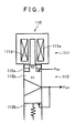
FIG. 9 , alinear solenoid valve 110 is formed by asolenoid portion 111 and avalve portion 112, and a protruding portion on which aplunger 111 d driven by acoil 111a abuts needs be formed in aspool 112p of thevalve portion 112. That is, a pressure-receiving area of anoil chamber 112a is a pressure receiving area obtained by subtracting an area A2 of the protruding portion from a pressure-receiving area A1 of theoil chamber 112b (A1 - A2). - Thus, the relation between a feedback force of the
oil chamber 112a that receives the circulation pressure PCIR and a feedback force of theoil chamber 112b that receives the working pressure PAPP is represented by the following expression.
- On the other hand, if a large driving force is transmitted from an engine to the torque converter while the vehicle is stopped or is moving at a low speed such as when the vehicle is started on an uphill road or the like, large differential rotation is produced between a pump impeller that rotates at the engine speed, and a turbine runner whose rotation is stopped. Thus, a phenomenon tends to occur that the internal pressure in the torque converter first increases due to stirring of oil, and then decreases rapidly.
- That is, when the vehicle is started or the like, as shown in
FIG. 10 , the circulation pressure PCIR varies so as to first increase and then decrease rapidly. However, since the working pressure PAPP that is output from thelinear solenoid valve 110 is "(A1 - A2)/A1 < 1," the working pressure PAPP varies less than the circulation pressure PCIR, based on the above expression (1), whereby the difference Pd between the circulation pressure PCIR and the working pressure PAPP may increase and decrease. Thus, thelinear solenoid valve 110 described inPatent Document 1 may not be able to maintain the differential pressure Pd at an intended value when the circulation pressure varies. - In particular, in recent years, a device is proposed without the hydraulic power transmission device such as the torque converter, which enables starting of the vehicle while slip-controlling a starting clutch. In such a device, however, the circulation pressure of the starting clutch varies upon such starting of the vehicle as described above, and thus the differential pressure of the starting clutch may not be maintained at an intended value, which may cause shocks or vibrations upon starting of the vehicle.
- Thus, it is an object of the present invention to provide a hydraulic control device of an automatic transmission which is capable of accurately performing engagement/disengagement control and slip control of a clutch even if a circulation pressure varies.
- According to the present invention (see, e.g.,
FIGS. 1 to 6 ), a hydraulic control device (11, 12, 13) of an automatic transmission (AT) includes: a circulation pressure supply portion (6, 7 inFIG. 1 ;6 , 17 inFIG. 5 ; and6 ,9 , 27 inFIG. 6 ) for supplying a circulation pressure (PCIR) to a starting device (2, 22, 32) having a clutch (3, 23, 33) capable of enabling and disabling power transmission between a driving source (EG) and an automatic speed change mechanism (40); and a pressure-regulating solenoid valve (101 to 105) capable of regulating a working pressure (PAPP) that engages and disengages the clutch (3, 23, 33) by a difference from the circulation pressure (PCIR), wherein the pressure-regulating solenoid valve (101 to 105) has a solenoid portion (11) that is driven electrically, and a spool portion (12 1 to 12 5 ) including a spool (12p) that is drivingly pressed by the solenoid portion (11). The hydraulic control device (11, 12, 13) is characterized in that the spool portion (121 to 125) includes a first feedback oil chamber (12b) for feeding back the working pressure (PAPP) to the spool (12p), and a second feedback oil chamber (12a) for feeding back the circulation pressure (PCIR) to the spool (12p) in a direction opposite to the first feedback oil chamber (12b), and a pressure-receiving area (A1 - A2) of the first feedback oil chamber (12b) and a pressure-receiving area (A1 - A2) of the second feedback oil chamber (12a) are set equal to each other in the spool (12p). - The present invention (see, e.g.,
FIGS. 1 and5 ) is characterized in that the starting device (2, 22) includes a hydraulic power transmission device (4) for performing the power transmission between the driving source (EG) and the automatic speed change mechanism (40) via a fluid, and the clutch is a lockup clutch (3, 23). - Specifically, the present invention (see, e.g.,
FIGS. 5 and6 ) is characterized by further including: a circulation pressure supply oil passage (c4) for supplying the circulation pressure (PCIR) from the circulation pressure supply portion (6, 17 inFIG. 5 ; and6 ,9 , 27 inFIG. 6 ) to a circulation pressure supply port (22d, 32d) of the starting device (22, 32); a circulation pressure discharge oil passage (d1) for discharging the circulation pressure (PCIR) in the starting device (22, 32) from a circulation pressure discharge port (22e, 32e) of the starting device (2, 22); a working pressure supply oil passage (e3) for supplying the working pressure (PAPP) from the pressure-regulating solenoid valve (10) to a working pressure supply port (22c, 32c) of the starting device (22, 32); and a circulation pressure introducing oil passage (c5) for introducing the circulation pressure (PCIR) into the second feedback oil chamber (12a) from one (e.g., 22d, 32d) of the circulation pressure supply port (22d, 32d) and the circulation pressure discharge port (22e, 32e) that is located closer to the clutch (22, 32). - The present invention (see, e.g.,
FIGS. 7 and8 ) is characterized in that the spool portion (124, 125) of the pressure-regulating solenoid valve (104, 105) has a main sleeve (12SA) that entirely contains the spool (12p) and slidably supports at least one end of the spool (12p), and a sub sleeve (12SB) that is interposed between the main sleeve (12SA) and the other end of the spool (12p) and slidably supports the other end of the spool (12p), and the spool is separated and formed into a first spool (12p1) that is slidably supported by the main sleeve (12SA), and a second spool (12p2) that is slidably supported by the sub sleeve (12SB). - The present invention (see, e.g.,
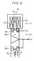
FIGS. 2 and3 ) is characterized in that the pressure-regulating solenoid valve (10) includes a spring (12s) for biasing the spool (12p) against a driving force of the solenoid portion (11), a relation of forces that are applied to the spool (12p) is represented by PCIR - PAPP = -(FSOL - FSP)/(A1 - A2) = Pd, where PAPP represents the working pressure that is fed back to the first feedback oil chamber (12b), PCIR represents the circulation pressure that is fed back to the second feedback oil chamber (12a), FSP represents a biasing force of the spring (12s) that biases the spool in such a direction that reduces an amount of communication between an input port (12d) and an output port (12c) of the pressure-regulating solenoid valve (10), FSOL represents the driving force of the solenoid portion (11), and A1 - A2 represents the pressure-receiving area of the first feedback oil chamber (12b) and the second feedback oil chamber (12a), and in a state in which the driving force FSOL is constantly output, the difference Pd between the circulation pressure PCIR and the working pressure PAPP is maintained constant even if the circulation pressure PCIR varies. - Note that the reference numerals in the parentheses are shown for reference to the drawings, and are given for convenience to facilitate understanding of the invention. Thus, these reference numerals do not affect the structure described in the claims.
- According to the present invention of
claim 1, the pressure-receiving area of the first feedback oil chamber and the pressure-receiving area of the second feedback oil chamber are set equal to each other in the spool. Thus, the oil pressure acting force of the working pressure of the first feedback oil chamber and that of the circulation pressure of the second feedback oil chamber can be equal to each other, whereby engagement/disengagement control and slip control of the clutch can be accurately performed. - According to the present invention of
claim 2, the starting device includes the hydraulic power transmission device for performing the power transmission between the driving source and the automatic speed change mechanism via a fluid, and the clutch is a lockup clutch. Thus, the circulation pressure varies significantly, especially in the state in which large differential rotation is generated in the hydraulic power transmission device. However, even if the circulation pressure varies significantly, the difference between the circulation pressure and the working pressure can always be maintained at an intended value, whereby engagement/disengagement control and slip control of the clutch can be accurately performed. - According to the present invention of
claim 3, the circulation pressure is introduced into the second feedback oil chamber from one of the circulation pressure supply port and the circulation pressure discharge port that is located closer to the clutch. Thus, a variation in the circulation pressure can be more accurately transmitted to the second feedback oil chamber, and the difference between the circulation pressure and the working pressure can be more accurately maintained at an intended value, whereby engagement/disengagement control and slip control of the clutch can be accurately performed. - According to the present invention of
claim 4, the spool is separated and formed into the first spool that is slidably supported by the main sleeve, and the second spool that is slidably supported by the sub sleeve. Thus, displacement of the centers due to a fitting error, a product error, or the like between the main sleeve and the sub sleeve can be absorbed by the separated portion therebetween, whereby especially the sealing capability between the sub sleeve and the second spool can be satisfactorily ensured. Thus, the length of the spool portion of the pressure-regulating solenoid valve in the axial direction can be reduced, which can contribute to implementation of a more compact hydraulic control device of the automatic transmission. -
- [
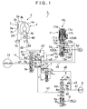
FIG. 1] FIG. 1 is a circuit diagram showing a hydraulic control device of an automatic transmission according to a first embodiment. - [
FIG. 2] FIG. 2 is an illustration schematically showing a linear solenoid valve. - [
FIG. 3] FIG. 3 is a timing chart showing the relation between a circulation pressure and a working pressure. - [
FIG. 4] FIG. 4 is a schematic diagram showing a general structure of a vehicle drive system to which the present invention can be applied. - [
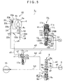
FIG. 5] FIG. 5 is a circuit diagram showing a hydraulic control device of an automatic transmission according to a second embodiment. - [
FIG. 6] FIG. 6 is a circuit diagram showing a hydraulic control device of an automatic transmission according to a third embodiment. - [
FIG. 7] FIG. 7 is a cross-sectional view showing a linear solenoid valve according to a fourth embodiment. - [
FIG. 8] FIG. 8 is a cross-sectional view showing a linear solenoid valve according to a fifth embodiment. - [
FIG. 9] FIG. 9 is an illustration schematically showing a conventional linear solenoid valve. - [
FIG. 10] FIG. 10 is a timing chart showing the relation between a circulation pressure and a working pressure in a conventional example. - A first embodiment of the present invention will be described below with reference to
FIGS. 1 to 4 . - First, the general structure of an automatic transmission and a vehicle drive system to which a
hydraulic control device 11 of an automatic transmission of the first embodiment can be applied will be described with reference toFIG. 4 . As shown inFIG. 4 , an automatic transmission AT is connected to an engine (a driving source) EG, and mainly includes astarting device 2, an automaticspeed change mechanism 40, and ahydraulic control device 1. Thestarting device 2 has atorque converter 4 and alockup clutch 3. The torque converter (a hydraulic power transmission device) 4 includes: apump impeller 4a coupled to afront cover 2A to which rotation from the engine EG is input; aturbine runner 4b which is positioned to face thepump impeller 4a so that power is hydraulically transmitted to theturbine runner 4b via oil, and which is connected to aninput shaft 40a of the automaticspeed change mechanism 40; and astator 4c which is positioned between thepump impeller 4a and theturbine runner 4b, and whose rotation is restricted to one direction by a one-way clutch 4d. - The lockup clutch (a clutch) 3 includes a
piston 3a positioned so as to be movable in the axial direction, and afriction material 3b provided on the outer periphery of thepiston 3a. Thepiston 3a is placed so as to separate an oil-tight space 2a from an oil-tight space 2b, and is drivingly moved to and away from thefront cover 2A by the differential pressure between thespace 2a and thespace 2b. That is, as the oil pressure in thespace 2b increases, thefriction material 3b is separated from the inner side surface of thefront cover 2A, and is disengagement-controlled. As the oil pressure in thespace 2a increases, thefriction material 3b is pressed against the inner side surface of thefront cover 2A, and is slip-controlled and engagement-controlled, whereby thelockup clutch 3 is engaged. Thus, when thelockup clutch 3 is engaged, thefront cover 2A is directly engaged with the input shaft of the automaticspeed change mechanism 40. That is, thetorque converter 4 is locked up. - The automatic
speed change mechanism 40 is hydraulically controlled by thehydraulic control device 11 to perform engagement/disengagement control of, e.g., friction engagement elements (clutches and brakes), not shown, thereby changing the speed ratio, namely shifting rotation of theinput shaft 40a to output the shifted speed from anoutput shaft 40b. Theoutput shaft 40b is connected to adifferential unit 45 via a propeller shaft or the like, and is structured to transmit driving rotation to right and leftdriving wheels - The hydraulic circuit structure in the
hydraulic control device 11 of the automatic transmission will be described in detail below. As shown inFIG. 1 , thehydraulic control device 11 of the automatic transmission includes anoil pump 5, a primary regulator valve (a circulation pressure supply portion) 6, a modulator valve (a circulation pressure supply portion) 7, alockup relay valve 8, a linear solenoid valve (SLU) (a pressure-regulating solenoid valve) 101, an oil cooler (COOLER) 15, and the like. - Note that the
hydraulic control device 11 of the automatic transmission includes various valves, oil passages, and the like for supplying oil pressure to hydraulic servos of the clutches and brakes of thespeed change mechanism 40, in addition to the parts shown inFIG. 1 . However, description of the parts other than a main part of the present invention will be omitted for convenience of explanation. - Reference character PSLT in
FIG. 1 represents an SLT pressure PSLT that is regulated and output from a linear solenoid valve SLT, not shown, based on a throttle opening or the like. Reference character PD inFIG. 1 represents a forward range pressure PD that is output from a manual shift valve, not shown, when in a forward range. - As shown in
FIG. 1 , thehydraulic control device 11 of the automatic transmission includes theoil pump 5 that is driven according to rotation of the engine EG, and an oil pressure is generated by sucking oil from an oil pan, not shown, by theoil pump 5 through a strainer. The oil pressure generated by theoil pump 5 is output to oil passages a1, a2, a3, a4, and a5, and is regulated to a line pressure PL by theprimary regulator valve 6. The line pressure PL and theprimary regulator valve 6 will be described in detail later. - The
primary regulator valve 6 includes aspool 6p, and aspring 6s for biasing thespool 6p upward in the drawing, and also includes anoil chamber 6a located above thespool 6p, anoil chamber 6b located below thespool 6p, a pressure-regulatingport 6c, adischarge port 6d, and a backpressure output port 6e. The SLT pressure PSLT is input from the linear solenoid valve SLT to theoil chamber 6b via an oil passages i1, and the line pressure PL, which will be described in detail later, is input to theoil chamber 6a via the oil passages a3, a4 as a feedback pressure. - The
spool 6p of theprimary regulator valve 6 is subjected to the biasing force of thespring 6s and the SLT pressure PSLT against the feedback pressure. That is, the position of thespool 6p is controlled mainly by the magnitude of the SLT pressure PSLT. When thespool 6p is located on the lower side in the drawing, the pressure-regulatingport 6c communicates with thedischarge port 6d. As thespool 6p is controlled to move to the upper side in the drawing based on the SLT pressure PSLT, the amount of communication (the throttle amount) between the pressure-regulatingport 6c and thedischarge port 6d is accordingly reduced (disconnected), while the amount of communication (the throttle amount) between the pressure-regulatingport 6c and the backpressure output port 6e is increased accordingly. That is, thespool 6p is controlled to move upward according to the magnitude of the SLT pressure PSLT that is input to theoil chamber 6b, and the amount of oil pressure that is discharged from thedischarge port 6d is adjusted, whereby an oil pressure of the pressure-regulatingport 6c is regulated. Thus, oil pressures of the oil passages a1, a2, a3, a4, and a5 are regulated as the line pressure PL according to the throttle opening. - The line pressure PL is supplied to the
modulator valve 7 via the oil passage a5. Themodulator valve 7 has a spool 7p, aspring 7s for biasing the spool 7p upward in the drawing, an input port 7a to which the line pressure PL is input via the oil passage a5, anoutput port 7b, and afeedback oil chamber 7c. If the line pressure PL is equal to or less than a predetermined value, themodulator valve 7 outputs the oil pressure as it is from theoutput port 7b as the circulation pressure PCIR. If the line pressure PL is equal to or higher than the predetermined value, a feedback pressure, which is input from theoutput port 7b to thefeedback oil chamber 7c via oil passages c1, c2, overcomes thespring 7s, and the amount of communication (the throttle amount) between the input port 7a and theoutput port 7b is reduced, and an oil pressure regulated to a fixed value is output as the circulation pressure PCIR. - Note that the line pressure PL is supplied not only to the
modulator valve 7, but also to a manual shift valve, various solenoid valves, and the like, not shown. In, e.g., stepped automatic transmissions, the line pressure PL is eventually supplied to hydraulic servos of clutches and brakes to establish a shift speed. In, e.g., belt-type continuously variable transmissions, the line pressure PL is supplied to hydraulic servos of forward/rearward switch clutches and brakes, and the like. Namely, the line pressure PL is used in each part as a source pressure in hydraulic control of the automatic transmission. - The
lockup relay valve 8 includes a spool 8p, and aspring 8s for biasing the spool 8p upward in the drawing, and includes anoil chamber 8a located above the spool 8p, aport 8b, aninput port 8c, aport 8d, aninput port 8e, aninput port 8f, an output port 8g, and aninput port 8h. - An
output port 12c of aspool portion 121 of thelinear solenoid valve 101 is connected to theoil chamber 8a via oil passages e1, e3, e4. When a working pressure PAPP is output from thelinear solenoid valve 101, the working pressure PAPP is input to theoil chamber 8a. That is, in the state in which no working pressure PAPP is output from thelinear solenoid valve 101, the spool 8p of thelockup relay valve 8 is located at a position shown in the left half of the valve in the drawing (hereinafter referred to as the "left-half position"). In the state in which the working pressure PAPP having a predetermined value or more is output from thelinear solenoid valve 101, the spool 8p of thelockup relay valve 8 overcomes the biasing force of thespring 8s, and is located at a position shown in the right half of the valve in the drawing (hereinafter referred to as the "right-half position"). That is, thelockup relay valve 8 is switched based on the input state of the working pressure PAPP. - If the spool 8p of the
lockup relay valve 8 is located at the left-half position, theinput port 8c communicates with theport 8d, and theinput port 8e communicates with the output port 8g. If the spool 8p is located at the right-half position, theinput port 8c communicates with theport 8b, theinput port 8e communicates with theport 8d, and theinput port 8h communicates with the output port 8g. - That is, if the spool 8p of the
lockup relay valve 8 is located at the left-half position, the circulation pressure PCIR, which is output from themodulator valve 7, is output from theport 8d to an oil passage f1 via an oil passage c3 and theinput port 8c, and is supplied from a lockup off port (L-UP OFF port) 2c of the startingdevice 2 into the startingdevice 2. The circulation pressure PCIR supplied into the startingdevice 2 is discharged from a lockup on port (L-UP ON port) 2d to an oil passage d2, is output from the output port 8g to an oil passage g1 via oil passages d3, d4 and theinput port 8f, and is supplied to theoil cooler 15. Oil supplied to theoil cooler 15 is cooled by theoil cooler 15, and is then returned to the oil pan, not shown, so as to be sucked again by theoil pump 5. - Note that at this time, the circulation pressure PCIR discharged to the oil passage d2 is supplied also to a second
feedback oil chamber 12a of thelinear solenoid valve 101, which will be described later, via the oil passage d3 and an oil passage d5. However, since thelinear solenoid valve 101 is not in a driven state, the circulation pressure PCIR does not affect the working pressure PAPP that will be described later. - The
linear solenoid valve 101 is roughly formed by asolenoid portion 11 and thespool portion 121. Thesolenoid portion 11 includes acoil 11 a for generating a magnetic field based on a current from a terminal 11t to which wirings are connected, acore member 11c for converging the magnetic field of the coil, aplunger 11b that is drawn downward in the drawing by the magnetic field from thecore member 11c, and ashaft 11d that is drivingly pressed downward in the drawing by theplunger 11b. - The
spool portion 121 includes aspool 12p that is drivingly pressed downward in the drawing by theshaft 11d, and aspring 12s for biasing thespool 12p upward in the drawing, and has the secondfeedback oil chamber 12a, theoutput port 12c, aninput port 12d, and a firstfeedback oil chamber 12b sequentially from above in the drawing. Thespool 12p is formed so that a part of thespool 12p located above the secondfeedback oil chamber 12a, and a part of thespool 12p located below the firstfeedback oil chamber 12b have a small land diameter, and a part of thespool 12p located between the secondfeedback oil chamber 12a and the firstfeedback oil chamber 12b has a land diameter larger than the small land diameter. - That is, as shown in
FIG. 2 , the secondfeedback oil chamber 12a and the firstfeedback oil chamber 12b are structured to have a pressure-receiving area "A1 - A2" obtained by the difference between a cross-sectional area A1 of the large land diameter and a cross-sectional area A2 of the small land diameter. - As shown in
FIG. 1 , when a current is supplied from the terminal 11t of thelinear solenoid valve 101 to thecoil 11a based on electronic control of a control portion, not shown, theshaft 11d electrically and drivingly presses thespool 12p downward in the drawing against the biasing force of thespring 12s. Thus, the amount of communication between theinput port 12d and theoutput port 12c is gradually increased, and the forward range pressure PD that is input to theinput port 12d is gradually output as the working pressure PAPP from theoutput port 12c to the oil passage e1. That is, the working pressure PAPP is controlled to increase based on the magnitude of the current. - When the working pressure PAPP is output from the
linear solenoid valve 101 to the oil passage e1, and the working pressure PAPP is increased to a predetermined value or more, the spool 8p of thelockup relay valve 8 is switched to the right-half position by the working pressure PAPP that is input to theoil chamber 8a via the oil passages e3, e4. When the spool 8p of thelockup relay valve 8 is located at the right-half position, the circulation pressure PCIR that is output from themodulator valve 7 is output from theport 8b to an oil passage d1 and the oil passage d2 via the oil passage c3 and theinput port 8c, and is supplied from the lockup onport 2d of the startingdevice 2 into the startingdevice 2. The working pressure PAPP that is input to theinput port 8e via the oil passages e1, e3 and an oil passage e5 is output from theport 8d to the oil passage f1, and is supplied from the lockup offport 2c into the startingdevice 2. - Thus, due to the difference between the circulation pressure PCIR in the
space 2a and the working pressure PAPP in thespace 2b in the startingdevice 2, that is, if the circulation pressure PCIR is larger than the working pressure PAPP, thepiston 3a is drivingly pressed against thefront cover 2A, and thefriction material 3b is pressed against the inner side surface of thefront cover 2A and is slip-controlled and engagement-controlled, whereby thelockup clutch 3 is engaged. - Note that when the
lockup clutch 3 is in the engaged state, the circulation pressure PCIR is not discharged from the startingdevice 2, but the back pressure of the line pressure PL which is output from the backpressure output port 6e of theprimary regulator valve 6 is input to theinput port 8h of thelockup relay valve 8 via an oil passage b1, is output from the output port 8g to the oil passage g1, and is supplied to theoil cooler 15. Similarly, oil supplied to theoil cooler 15 is cooled by theoil cooler 15, and is then returned to the oil pan, not shown, so as to be sucked again by theoil pump 5. - In the
hydraulic control device 11 of the automatic transmission, when thelockup clutch 3 is in the engaged state, the circulation pressure PCIR that is output to the oil passage d1 is input to the secondfeedback oil chamber 12a of thelinear solenoid valve 101 via the oil passages d3, d5, and the working pressure PAPP that is output from theoutput port 12c of thelinear solenoid valve 101 is input to the firstfeedback oil chamber 12b via the oil passages e1, e2 so as to provide feedback action in the direction opposite to the firstfeedback oil chamber 12b. - Thus, as shown in
FIG. 2 , the relation of forces in thelinear solenoid valve 101 is represented by the following expression.
This expression can be rewritten as follows.

where "FSP" represents a biasing force of thespring 12s, and "FSOL" represents a driving force of theshaft 11d, and "A1 - A2" represents a pressure-receiving area. - Accordingly, in the state in which the driving force FSOL of the
shaft 11d having a constant value is output, the pressure-receiving area "A1 - A2" and the biasing force FSP of the spring are also constant, and thus, the relation between the working pressure PAPP and the circulation pressure PCIR is such that there is a constant difference Pd between the working pressure PAPP and the circulation pressure PCIR. That is, by setting the pressure-receiving area "A1 - A2" of the firstfeedback oil chamber 12b and the pressure-receiving area "A1 - A2" of the secondfeedback oil chamber 12a equal to each other, an oil pressure acting force of the working pressure PAPP of the firstfeedback oil chamber 12b and that of the circulation pressure PCIR of the secondfeedback oil chamber 12a are set equal to each other with respect to thespool 12p. - Thus, as shown in
FIG. 3 , for example, even if differential rotation is generated in thetorque converter 4, and the circulation pressure PCIR varies significantly, the working pressure PAPP varies so as to maintain the constant difference Pd by feedback control. That is, the difference Pd between the circulation pressure PCIR in thespace 2a and the working pressure PAPP in thespace 2b in the startingdevice 2 does not vary and can always be maintained at an intended value (a constant value). Thus, slip control and engagement control can be accurately performed. - As described above, the
hydraulic control device 11 of the automatic transmission is structured so that the oil pressure acting force of the working pressure PAPP of the firstfeedback oil chamber 12b and that of the circulation pressure PCIR of the secondfeedback oil chamber 12a are set equal to each other with respect to thespool 12p of thespool portion 121 of thesolenoid valve 101. Thus, even if the circulation pressure PCIR varies, the difference Pd between the circulation pressure PCIR and the working pressure PAPP can always be maintained at the intended value, whereby engagement/disengagement control and slip control of the clutch can be accurately performed. - Specifically, since the pressure-receiving area "A1 - A2" of the first
feedback oil chamber 12b and the pressure-receiving area "A1 - A2" of the secondfeedback oil chamber 12a are set equal to each other in thespool 12p, the oil pressure acting force of the working pressure PAPP of the firstfeedback oil chamber 12b and that of the circulation pressure PCIR of the secondfeedback oil chamber 12a can be equal to each other. - Moreover, the starting
device 2 includes thetorque converter 4 that transmits power between the engine EG and the automaticspeed change mechanism 40 via a fluid, and the clutch is thelockup clutch 3 that can lock up thetorque converter 4. Thus, the circulation pressure PCIR varies significantly, especially in the state in which large differential rotation is generated in thetorque converter 4. However, even if the circulation pressure PCIR varies significantly, the difference Pd between the circulation pressure PCIR and the working pressure PAPP can always be maintained at the intended value, whereby engagement/disengagement control and slip control of thelockup clutch 3 can be accurately performed. - A second embodiment, which is partially modified from the first embodiment, will be described below with reference to
FIG. 5 . Note that in the description of the second embodiment, the parts similar to those of the first embodiment are denoted with the same reference characters, and description thereof will be omitted. - A
hydraulic control device 12 of an automatic transmission according to the second embodiment is modified from thehydraulic control device 11 of the automatic transmission according to the first embodiment in the structure of a startingdevice 22 and a portion for supplying a circulation pressure PCIR. - That is, as shown in
FIG. 5 , the startingdevice 22 includes a lockup on port (a working pressure supply port) 22c for inputting a working pressure PAPP via an oil passage e3 (a working pressure supply oil passage), an input port (IN) (a circulation pressure supply port) 22d for inputting the circulation pressure PCIR via an oil passage c4 (a circulation pressure supply oil passage), and a discharge port (OUT) (a circulation pressure discharge port) 22e for discharging the circulation pressure PCIR. The startingdevice 22 is formed by a so-called three-way starting device 22. Thus, the startingdevice 22 is always supplied with the circulation pressure PCIR from theinput port 22d, and the circulation pressure PCIR, which has circulated in the startingdevice 22, is output from thedischarge port 22e to an oil passage d1(a circulation pressure discharge oil passage) with anorifice 24 inserted therein, whereby the pressure in aspace 22a of the startingdevice 22 is maintained at a substantially constant value. - A lockup clutch (a clutch) 23 includes a
support member 23a that is placed so as to be movable in the axial direction, and a plurality offriction plates 23b that are supported by thesupport member 23a. Thefriction plates 23b are engagement/disengagement controlled and slip-controlled by the difference in pressure between thespace 22a and aspace 22b. That is, if the working pressure PAPP on thespace 22b side is lower than the circulation pressure PCIR on thespace 22a side, thefriction plates 23b are disengagement-controlled. If the working pressure PAPP on thespace 22b side is higher than the circulation pressure PCIR in thespace 22a, thefriction plates 23b are slip-controlled and engagement-controlled, whereby thelockup clutch 23 is engaged. When thelockup clutch 23 is engaged, afront cover 2A is directly engaged with an input shaft of an automaticspeed change mechanism 40. That is, thetorque converter 4 is locked up. - In the second embodiment, the back pressure of a line pressure PL which is output from a back
pressure output port 6e of a primary regulator valve (a circulation pressure supply portion) 6 is input to amodulator valve 17 via oil passages b1, b2. The modulator valve (the circulation pressure supply portion) 17 has a spool 17p, aspring 17s for biasing the spool 17p upward in the drawing, aninput port 17a through which the back pressure of the line pressure PL is input via the oil passage b2, an output port 17b, and afeedback oil chamber 17c. If the back pressure of the line pressure PL is equal to or less than a predetermined value, themodulator valve 17 outputs the oil pressure as it is from the output port 17b as the circulation pressure PCIR. If the back pressure of the line pressure PL is equal to or higher than the predetermined value, a feedback pressure, which is input from the output port 17b to thefeedback oil chamber 17c via oil passages c1, c2, overcomes thespring 17s, whereby the communication amount (the throttle amount) between theinput port 17a and the output port 17b is reduced, and an oil pressure regulated to a fixed value is output as the circulation pressure PCIR. - Then, the circulation pressure PCIR using the back pressure of the line pressure PL is input to the
input port 22d of the startingdevice 22 via an oil passage c3 and the oil passage c4, and is also input to a secondfeedback oil chamber 12a of alinear solenoid valve 102 via an oil passage c5 (a circulation pressure introducing oil passage). - Note that the back pressure of the line pressure PL which is output from the back
pressure output port 6e of theprimary regulator valve 6 is supplied to an oil cooler 15 via the oil passage b1 and an oil passage b3. Oil supplied to theoil cooler 15 is cooled by theoil cooler 15, and is then returned to an oil pan, not shown, so as to be sucked again by anoil pump 5. - The
hydraulic control device 12 of the automatic transmission of the second embodiment having the above structure is structured so that the oil pressure acting force of the working pressure PAPP of the firstfeedback oil chamber 12b and that of the circulation pressure PCIR of the secondfeedback oil chamber 12a are equal to each other with respect to thespool 12p of thespool portion 122 of thesolenoid valve 102. Thus, even if the circulation pressure PCIR varies, the difference Pd between the circulation pressure PCIR and the working pressure PAPP can always be maintained at an intended value, whereby engagement/disengagement control and slip control of the clutch can be accurately performed. - In particular, in the
hydraulic control device 12 of the automatic transmission according to the second embodiment, the circulation pressure PCIR is introduced into the secondfeedback oil chamber 12a from the oil passage c4, which is connected to theinput port 22d located closer to the lockup clutch 23 out of theinput port 22d and thedischarge port 22e of the startingdevice 22, via the oil passage c5. Thus, for example, an oil pressure at a position closer to the lockup clutch 23 can be fed back, as compared to, e.g., the case where the circulation pressure PCIR, which is discharged from the oil passage d1 connected to thedischarge port 22e, is introduced into the secondfeedback oil chamber 12a. Accordingly, a variation in circulation pressure PCIR can be more accurately transmitted to the secondfeedback oil chamber 12a, and the difference Pd between the circulation pressure PCIR and the working pressure PAPP can be more accurately maintained at the intended value, whereby engagement/disengagement control and slip control of the lockup clutch 23 can be accurately performed. - Note that since the structures, functions, and effects of the parts other than those described above are similar to the first embodiment, description thereof will be omitted.
- A third embodiment, which is partially modified from the first and second embodiments, will be described below with reference to
FIG. 6 . Note that in the description of the third embodiment, the parts similar to those of the first and second embodiments are denoted with the same reference characters, and description thereof will be omitted. - A
hydraulic control device 13 of an automatic transmission according to the third embodiment is modified from thehydraulic control devices device 32 and a portion for supplying a circulation pressure PCIR. - That is, as shown in
FIG. 6 , as in the second embodiment, the startingdevice 32 includes a lockup on port (a working pressure supply port) 32c for inputting a working pressure PAPP via an oil passage e3 (a working pressure supply oil passage), an input port (IN) (a circulation pressure supply port) 32d for inputting the circulation pressure PCIR via an oil passage c4 (a circulation pressure supply oil passage), and a discharge port (OUT) (a circulation pressure discharge port) 32e for discharging the circulation pressure PCIR, and is formed by a so-called three-way starting device 32. Thus, the startingdevice 32 is always supplied with the circulation pressure PCIR from the input port 32d, and the circulation pressure PCIR, which has circulated in the startingdevice 32, is output from thedischarge port 32e to an oil passage d1 (a circulation pressure discharge oil passage) with anorifice 24 inserted therein, whereby the pressure on aspace 32a side of the startingdevice 32 is maintained at a substantially constant value. - The starting
device 32 of the third embodiment does not include a torque converter, and includes only a startingclutch 33. Thus, when, e.g., starting a vehicle, the startingclutch 33 is slip-controlled and engagement-controlled, whereby transmission of a driving force is achieved while absorbing the differential rotation between an engine EG and an input shaft of an automaticspeed change mechanism 40. - The starting clutch (a clutch) 33 includes a
support member 33a that is placed so as to be movable in the axial direction, and a plurality offriction plates 33b that are supported by thesupport member 33a. Thefriction plates 33b are engagement/disengagement controlled and slip-controlled by the difference in pressure between thespace 32a and aspace 32b. That is, if the working pressure PAPP on thespace 32b side is lower than the circulation pressure PCIR on thespace 32a side, thefriction plates 33b are disengagement-controlled. If the working pressure PAPP on thespace 32b side is higher than the circulation pressure PCIR on thespace 32a side, thefriction plates 33b are slip-controlled and engagement-controlled, whereby the startingclutch 33 is engaged. - In the third embodiment, the back pressure of a line pressure PL which is output from a back
pressure output port 6e of a primary regulator valve (a circulation pressure supply portion) 6 is input to asecondary regulator valve 9 via oil passages b1, b2. The secondary regulator valve (the circulation pressure supply portion) 9 includes aspool 9p, and aspring 9s for biasing thespool 9p upward in the drawing, and also includes anoil chamber 9a located above thespool 9p, anoil chamber 9b located below thespool 9p, a pressure-regulating port 9c, adischarge port 9d, and a backpressure output port 9e. An SLT pressure PSLT is input from the linear solenoid valve SLT, which is described above, to theoil chamber 9b via oil passages i1,i3, and a secondary pressure PSEC, which will be described in detail later, is input to theoil chamber 9a via the oil passages b2, b3, b4 as a feedback pressure. Note that the SLT pressure PSLT is input from the linear solenoid valve SLT to anoil chamber 6b of theprimary regulator valve 6 via the oil passage i1 and an oil passage i2. - The
spool 9p of thesecondary regulator valve 9 is subjected to the biasing force of thespring 9s and the SLT pressure PSLT against the feedback pressure. That is, the position of thespool 9p is controlled mainly by the magnitude of the SLT pressure PSLT. When thespool 9p is located on the lower side in the drawing, the pressure-regulating port 9c communicates with thedischarge port 9d. As thespool 9p is controlled to move to the upper side in the drawing based on the SLT pressure PSLT, the amount of communication (the throttle amount) between the pressure-regulating port 9c and thedischarge port 9d is accordingly reduced (disconnected), and the amount of communication (the throttle amount) between the pressure-regulating port 9c and the backpressure output port 9e is increased accordingly. That is, thespool 9p is controlled to move upward according to the magnitude of the SLT pressure PSLT that is input to theoil chamber 9b, and the amount of oil pressure that is discharged from the discharge port 9c is adjusted, whereby an oil pressure of the pressure-regulatingport 9d is regulated. Thus, oil pressures of the oil passages b1, b2, b3, b4, b5 are regulated as the secondary pressure PSEC according to the throttle opening. - The secondary pressure PSEC regulated by the
secondary regulator valve 9 is input to amodulator valve 27. The modulator valve (a circulation pressure supply portion) 27 has aspool 27p, aspring 27s for biasing thespool 27p upward in the drawing, aninput port 27a to which the secondary pressure PSEC is input via the oil passage b5, an output port 27b, and afeedback oil chamber 27c. If the secondary pressure PSEC is equal to or less than a predetermined value, themodulator valve 27 outputs the oil pressure as it is from the output port 27b as the circulation pressure PCIR. If the secondary pressure PSEC is equal to or higher than the predetermined value, a feedback pressure, which is input from the output port 27b to thefeedback oil chamber 27c via oil passages c1, c2, overcomes thespring 27s, and the amount of communication (the throttle amount) between theinput port 27a and the output port 27b is reduced, and an oil pressure regulated to a fixed value is output as the circulation pressure PCIR. - The circulation pressure PCIR using the secondary pressure PSEC is input to the input port 32d of the starting
device 32 via an oil passage c3 and the oil passage c4, and is also input to a secondfeedback oil chamber 12a of alinear solenoid valve 103 via an oil passage c5 (a circulation pressure introducing oil passage). - Note that the back pressure of the secondary pressure PSEC that is output from the back
pressure output port 9e of thesecondary regulator valve 9 is supplied to an oil cooler 15 via an oil passage g1. Oil supplied to theoil cooler 15 is cooled by theoil cooler 15, and is then returned to an oil pan, not shown, so as to be sucked again by anoil pump 5. - The
hydraulic control device 13 of the automatic transmission of the third embodiment having the above structure is structured so that the oil pressure acting force of the working pressure PAPP of a firstfeedback oil chamber 12b and that of the circulation pressure PCIR of the secondfeedback oil chamber 12a are equal to each other with respect to thespool 12p of thespool portion 123 of thesolenoid valve 103. Thus, even if the circulation pressure PCIR varies, the difference Pd between the circulation pressure PCIR and the working pressure PAPP can always be maintained at an intended value, whereby engagement/disengagement control and slip control of the clutch can be accurately performed. - In particular, in the
hydraulic control device 13 of the automatic transmission according to the third embodiment, the circulation pressure PCIR is introduced into the secondfeedback oil chamber 12a from the oil passage c4, which is connected to the input port 32d located closer to the startingclutch 33 out of the input port 32d and thedischarge port 32e of the startingdevice 32, via the oil passage c5. Thus, for example, an oil pressure at a position closer to the startingclutch 33 can be fed back, as compared to, e.g., the case where the circulation pressure PCIR, which is discharged from the oil passage d1 connected to thedischarge port 32e, is introduced into the secondfeedback oil chamber 12a. Accordingly, a variation in circulation pressure PCIR can be more accurately transmitted to the secondfeedback oil chamber 12a, and the difference Pd between the circulation pressure PCIR and the working pressure PAPP can be more accurately maintained at the intended value, whereby engagement/disengagement control and slip control of the startingclutch 33 can be accurately performed. - Note that since the structures, functions, and effects of the parts other than those described above are similar to the first and second embodiments, description thereof will be omitted.
- A fourth embodiment, which is partially modified from the first to third embodiments, will be described with reference to
FIG. 7 . Note that in the description of the fourth embodiment, the parts similar to those of the first to third embodiments are denoted with the same reference characters, and description thereof will be omitted. - The fourth embodiment is partially modified from the
hydraulic control device 1 of the automatic transmission according to the first to third embodiments in the structure of thespool portion 12 of thelinear solenoid valve 10. - As described above, in the
linear solenoid valve 10 of thehydraulic control device 1 of the automatic transmission, the pressure-receiving area of the secondfeedback oil chamber 12a and the pressure-receiving area of the firstfeedback oil chamber 12b are set equal to each other. Accordingly, thespool 12p needs to be formed so as to have a thin (small) land diameter in one end (a portion the slides with respect to a main sleeve 12SA), have a thick (large) land diameter in an intermediate portion, and have a thin (small) land diameter in the other end. Thus, in the structures of the first to third embodiments (seeFIGS. 1 ,5 , and6 ), when manufacturing thespool portion 12 of thesolenoid valve 10, thespool 12p is inserted into the main sleeve 12SA from the one end (the lower side in the drawing) of thespool 12p, and a sub sleeve 12SB is fittingly inserted between the other end (the upper side in the drawing) of thespool 12p and the main sleeve 12SA, and then thesolenoid portion 11 is attached, whereby thespool portion 12 is completed. - However, in the structures of the first to third embodiments (see
FIGS. 1 ,5 , and6 ), an error may be caused between the center of the main sleeve 12SA and the center of the sub sleeve 12SB due to a fitting error between the main sleeve 12SA and the sub sleeve 12SB, a product error of the sub sleeve 12SB, or the like, and the center of thespool 12p does not necessarily match the center of the sub sleeve 12SB. That is, the three centers, namely the center of the main sleeve 12SA, the center of the sub sleeve 12SB, and the center of thespool 12p, can be slightly displaced from each other due to an error or the like. In particular, displacement between the center of thespool 12p and the center of the sub sleeve 12SB affects the sealing capability between thespool 12p and the sub sleeve 12SB. Thus, in order to ensure the sealing capability, the amount by which thespool 12p and the sub sleeve 12SB overlap each other in the axial direction needs to be increased, which increases the length of thespool portion 12. - Thus, in a
spool portion 124 of alinear solenoid valve 104 of the fourth embodiment, as shown inFIG. 7 , thespool 12p is separated into two parts, and is formed by afirst spool 12p1 and asecond spool 12p2. - More specifically, as shown in
FIG. 7 , thespool portion 124 of thelinear solenoid valve 104 in the fourth embodiment includes: thefirst spool 12p1 having a small-diameter land portion 12pr1, a large-diameter land portion 12pr2, and a large-diameter land portion 12pr3; thesecond spool 12p2 having a large-diameter land portion 12pr4 and a small-diameter land portion 12pr5; a cylindrical sub sleeve 12SB; and a main sleeve 12SA entirely containing these elements. - The
first spool 12p1 is structured so that the secondfeedback oil chamber 12a is formed by the difference in pressure-receiving area "A1 - A2" which is produced by the difference in diameter between the small-diameter land portion 12pr1 and the large-diameter land portion 12pr2, and the communication state between anoutput port 12c and aninput port 12d, and the communication state between theoutput port 12c and a drain port EX are adjusted by the position of the gap between the large-diameter land portion 12pr2 and the large-diameter land portion 12pr3 in the axial direction, namely by the position of thefirst spool 12p1 in the axial direction. Each land portion 12pr1, 12pr2, 12pr3 (that is, at least one end) of thefirst spool 12p1 is slidably supported on the inner periphery of the main sleeve 12SA. - On the other hand, the
second spool 12p2 has its upper end in the drawing in contact with the lower end of thefirst spool 12p1 in the drawing, and is completely separated from thefirst spool 12p1. The firstfeedback oil chamber 12b is formed by the difference in pressure-receiving area "A1 - A2" which is produced by the difference in diameter between the large-diameter land portion 12pr4 and the small-diameter land portion 12pr5. The sub sleeve 12SB is interposed between the main sleeve 12SA and the land portions 12pr4, 12pr5 of thesecond spool 12p2 so as to fill the gap therebetween, and each land portion 12pr4, 12pr5 (that is, the other end) of thesecond spool 12p2 is slidably supported on the inner periphery of the sub sleeve 12SB. - Note that a drain port EX is formed in the portion (that is, the separated portion) where the lower end of the
first spool 12p1 in the drawing contacts the upper end of thesecond spool 12p2 in the drawing, so that the drive states of thefirst spool 12p1 and thesecond spool 12p2 are not affected. The lower end of the sub sleeve 12SB in the drawing serves as acap portion 12c, and thecap portion 12c is screwed in the main sleeve 12SA, and contains aspring 12s in a contracted state between thecap portion 12c and thesecond spool 12p2. - The
spool portion 124 of thelinear solenoid valve 104 structured as described above is assembled by attaching the main sleeve 12SA to asolenoid portion 11 by caulking or the like, sequentially inserting thefirst spool 12p1 and thesecond spool 12p2 into a hollow portion of the main sleeve 12SA, fittingly inserting the sub sleeve 12SB around thesecond spool 12p2, and screwing thecap portion 12c in the main sleeve 12SA with thespring 12s inserted therein. - As described above, according to the
linear solenoid valve 104 of the fourth embodiment, the spool is separated and formed into thefirst spool 12p1 that is slidably supported by the main sleeve 12SA, and thesecond spool 12p2 that is slidably supported by the sub sleeve 12SB. Thus, the displacement of the centers due to a fitting error, a product error, or the like between the main sleeve 12SA and the sub sleeve 12SB can be absorbed by the separated portion between thefirst spool 12p1 and thesecond spool 12p2, whereby especially the sealing capability between the sub sleeve 12SB and thesecond spool 12p2 can be satisfactorily ensured. Thus, even if the drain port EX needs to be additionally provided in the separate portion between thefirst spool 12p1 and thesecond spool 12p2, the overall length of thespool portion 124 of thelinear solenoid valve 104 in the axial direction can be reduced, which can contribute to implementation of a more compacthydraulic control device 1 of the automatic transmission. - Note that since the structures, functions, and effects of the parts other than those described above are similar to the first to third embodiments, description thereof will be omitted.
- A fifth embodiment, which is partially modified from the fourth embodiment, will be described below with reference to
FIG. 8 . Note that in the description of the fifth embodiment, the parts similar to those of the first to fourth embodiments are denoted with the same reference characters, and description thereof will be omitted. - A
spool portion 125 of asolenoid valve 105 of the fifth embodiment is modified from thespool portion 124 of thesolenoid valve 104 of the fourth embodiment in the structures of thesecond spool 12p2 and the sub sleeve 12SB and the position where thespring 12s is placed. - More specifically, as shown in
FIG. 8 , thespool portion 125 of thelinear solenoid valve 105 of the fifth embodiment includes: afirst spool 12p1 having a small-diameter land portion 12pr1, a large-diameter land portion 12pr2, and a large-diameter land portion 12pr3; a substantially columnarsecond spool 12p2; a cylindrical sub sleeve 12SB; and a man sleeve 12SA entirely containing these elements. - In the
spool portion 125 of the present embodiment, the outer diameter of thesecond spool 12p2 is set so that the cross-sectional area of thesecond spool 12p2 is equal to the difference in pressure-receiving area "A1 - A2" between the small-diameter land portion 12pr1 and the large-diameter land portion 12pr2 of thefirst spool 12p1, namely so that an oil pressure acting area of the firstfeedback oil chamber 12b and an oil pressure acting area of the secondfeedback oil chamber 12a are set equal to each other. In thespool portion 125, the lower end of the sub sleeve 12SB in the drawing serves as acap portion 12c, and thecap portion 12c is screwed in the main sleeve 12SA, and contains aspring 12s in a compressed state between the lower end of thefirst spool 12p1 in the drawing and the upper end of the sub sleeve 12SB in the drawing (that is, in the separated portion between thefirst spool 12p1 and thesecond spool 12p2). - The
spool portion 125 of thelinear solenoid valve 105 structured as described above is assembled by attaching the main sleeve 12SA to asolenoid portion 11 by caulking or the like, sequentially inserting thefirst spool 12p1 and thespring 12s into a hollow portion of the main sleeve 12SA, and inserting the sub sleeve 12SB, which has thesecond spool 12p2 inserted therein, into the main sleeve 12SA by screwing thecap portion 12c in the main sleeve 12SA. - As described above, according to the
spool portion 125 of thelinear solenoid valve 105 of the fifth embodiment, no land portion need be provided in thesecond spool 12p2, whereby thesecond spool 12p2 can be shortened, and thus the length of thespool portion 125 in the axial direction can be reduced. Moreover, since thespring 12s is placed in the separated portion between thefirst spool 12p1 and thesecond spool 12p2, a drain port EX provided in the separated portion between thefirst spool 12p1 and thesecond spool 12p2 can be used also as a drain port EX for draining an oil pressure in a chamber in which thespring 12s is provided (seeFIG. 7 ). Thus, the number of drain ports EX can be reduced by one, and the length of thespool portion 125 in the axial direction can be reduced, which can contribute to implementation of a more compacthydraulic control device 1 of the automatic transmission. - Note that since the structures, functions, and effects of the parts other than those described above are similar to the first to fourth embodiments, description thereof will be omitted.
- Note that the first to fifth embodiments are described with respect to examples in which the
hydraulic control device 1 is used for the automaticspeed change mechanism 40 of the structure in which the engine EG is mounted in the longitudinal direction with respect to the traveling direction of the vehicle as in the front-engine, rear-wheel drive (FR) type, as shown inFIG. 4 . However, the present invention is not limited to this, and thehydraulic control device 1 may be used for automatic speed change mechanisms of the structure in which the engine EG is mounted in the transverse direction with respect to the traveling direction of the vehicle as in the front-engine, front-wheel-drive (FF) type. It is to be understood that the automatic speed change mechanism may be an automatic speed change mechanism of any type of automatic transmission such as a stepped automatic transmission and a belt type or toroidal type continuously variable transmission. -
FIG. 4 is described with respect to an example that is used in the first embodiment. However, it is to be understood that the vehicle can be similarly structured in the second and third embodiments as well by placing the starting device and the hydraulic control device in a similar manner. - The embodiments of the present invention are described with respect to examples in which an internal combustion engine is used as a driving source. However, it is to be understood that the hydraulic control device of the automatic transmission of the present invention may also be applied to hybrid vehicles provided with a motor generator.
- The hydraulic control device of the automatic transmission of the present invention can be used as a hydraulic control device of automatic transmissions that are mounted on passenger cars, trucks, or the like, and is especially preferable when used in automatic transmissions that are required to accurately perform engagement/disengagement control and slip control of a clutch for enabling and disabling power transmission between a driving source and an automatic speed change mechanism.
-
- 11, 12, 13
- hydraulic control device of automatic transmission
- 2
- starting device
- 3
- clutch, lockup clutch
- 4
- hydraulic power transmission device (torque converter)
- 6
- circulation pressure supply portion (primary regulator valve)
- 7
- circulation pressure supply portion (modulator valve)
- 9
- circulation pressure supply portion (secondary regulator valve)
- 101 to 105
- pressure-regulating solenoid valve (linear solenoid valve)
- 11
- solenoid portion
- 121 to 125
- spool portion
- 12SA
- main sleeve
- 12SB
- sub sleeve
- 12a
- second feedback oil chamber
- 12b
- first feedback oil chamber
- 12p
- spool
- 12p1
- first spool
- 12p2
- second spool
- 12s
- spring
- 17
- circulation pressure supply portion (modulator valve)
- 22
- starting device
- 22c
- working pressure supply port (lockup on port)
- 22d
- circulation pressure supply port (input port)
- 22e
- circulation pressure discharge port (discharge port)
- 23
- clutch, lockup clutch
- 27
- circulation pressure supply portion (modulator valve)
- 32
- starting device
- 32c
- working pressure supply port (lockup on port)
- 32d
- circulation pressure supply port (input port)
- 32e
- circulation pressure discharge port (discharge port)
- 33
- clutch (starting clutch)
- 40
- automatic speed change mechanism
- AT
- automatic transmission
- EG
- driving source (engine)
- PCIR
- circulation pressure
- PAPP
- working pressure
- c4
- circulation pressure supply oil passage (oil passage)
- c5
- circulation pressure introducing oil passage (oil passage)
- d1
- circulation pressure discharge oil passage (oil passage)
- e3
- circulation pressure supply oil passage (oil passage)
Claims (5)
- A hydraulic control device of an automatic transmission, including: a circulation pressure supply portion for supplying a circulation pressure to a starting device having a clutch capable of enabling and disabling power transmission between a driving source and an automatic speed change mechanism; and a pressure-regulating solenoid valve capable of regulating a working pressure that engages and disengages the clutch by a difference from the circulation pressure, wherein the pressure-regulating solenoid valve has a solenoid portion that is driven electrically, and a spool portion including a spool that is drivingly pressed by the solenoid portion, the hydraulic control device characterized in that
the spool portion includes a first feedback oil chamber for feeding back the working pressure to the spool, and a second feedback oil chamber for feeding back the circulation pressure to the spool in a direction opposite to the first feedback oil chamber, and
a pressure-receiving area of the first feedback oil chamber and a pressure-receiving area of the second feedback oil chamber are set equal to each other in the spool. - The hydraulic control device of the automatic transmission according to claim 1, characterized in that
the starting device includes a hydraulic power transmission device for performing the power transmission between the driving source and the automatic speed change mechanism via a fluid, and
the clutch is a lockup clutch. - The hydraulic control device of the automatic transmission according to claim 1 or 2, characterized by further comprising:a circulation pressure supply oil passage for supplying the circulation pressure from the circulation pressure supply portion to a circulation pressure supply port of the starting device;a circulation pressure discharge oil passage for discharging the circulation pressure in the starting device from a circulation pressure discharge port of the starting device;a working pressure supply oil passage for supplying the working pressure from the pressure-regulating solenoid valve to a working pressure supply port of the starting device; anda circulation pressure introducing oil passage for introducing the circulation pressure into the second feedback oil chamber from one of the circulation pressure supply port and the circulation pressure discharge port that is located closer to the clutch.
- The hydraulic control device of the automatic transmission according to any one of claims 1 to 3, characterized in that
the spool portion of the pressure-regulating solenoid valve has a main sleeve that entirely contains the spool and slidably supports at least one end of the spool, and a sub sleeve that is interposed between the main sleeve and the other end of the spool and slidably supports the other end of the spool, and
the spool is separated and formed into a first spool that is slidably supported by the main sleeve, and a second spool that is slidably supported by the sub sleeve. - The hydraulic control device of the automatic transmission according to any one of claims 1 to 4, characterized in that
the pressure-regulating solenoid valve includes a spring for biasing the spool against a driving force of the solenoid portion,
a relation of forces that are applied to the spool is represented by
where PAPP represents the working pressure that is fed back to the first feedback oil chamber, PCIR represents the circulation pressure that is fed back to the second feedback oil chamber, FSP represents a biasing force of the spring that biases the spool in such a direction that reduces an amount of communication between an input port and an output port of the pressure-regulating solenoid valve, FSOL represents the driving force of the solenoid portion, and A1 - A2 represents the pressure-receiving area of the first feedback oil chamber and the second feedback oil chamber, and
in a state in which the driving force FSOL is constantly output, the difference Pd between the circulation pressure PCIR and the working pressure PAPP is maintained constant even if the circulation pressure PCIR varies.
Applications Claiming Priority (3)
| Application Number | Priority Date | Filing Date | Title |
|---|---|---|---|
| JP2009224211 | 2009-09-29 | ||
| JP2010060570A JP2011094786A (en) | 2009-09-29 | 2010-03-17 | Hydraulic control device for automatic transmission |
| PCT/JP2010/005667 WO2011039963A1 (en) | 2009-09-29 | 2010-09-16 | Hydraulic control device for automatic transmission |
Publications (1)
| Publication Number | Publication Date |
|---|---|
| EP2410211A1 true EP2410211A1 (en) | 2012-01-25 |
Family
ID=43825816
Family Applications (1)
| Application Number | Title | Priority Date | Filing Date |
|---|---|---|---|
| EP10820089A Withdrawn EP2410211A1 (en) | 2009-09-29 | 2010-09-16 | Hydraulic control device for automatic transmission |
Country Status (6)
| Country | Link |
|---|---|
| US (1) | US20110132717A1 (en) |
| EP (1) | EP2410211A1 (en) |
| JP (1) | JP2011094786A (en) |
| KR (1) | KR20120024663A (en) |
| CN (1) | CN102449355A (en) |
| WO (1) | WO2011039963A1 (en) |
Families Citing this family (10)
| Publication number | Priority date | Publication date | Assignee | Title |
|---|---|---|---|---|
| JP5434946B2 (en) * | 2011-03-30 | 2014-03-05 | アイシン・エィ・ダブリュ株式会社 | Hydraulic control device |
| JPWO2014157544A1 (en) * | 2013-03-29 | 2017-02-16 | アイシン・エィ・ダブリュ株式会社 | Hydraulic control device and hydraulic control method |
| DE102013014558A1 (en) * | 2013-08-31 | 2015-03-05 | Hydac Fluidtechnik Gmbh | Valve and its use for a clutch |
| DE112014005042T5 (en) * | 2013-12-26 | 2016-09-01 | Aisin Aw Co., Ltd. | Hydraulic control device of an automatic transmission |
| JP2015145725A (en) * | 2014-01-31 | 2015-08-13 | ボーグワーナー インコーポレーテッド | Latch solenoid regulator valve |
| CN104141765B (en) * | 2014-05-14 | 2016-09-21 | 贵州凯星液力传动机械有限公司 | A kind of converter coupling control valve |
| JP6459527B2 (en) * | 2015-01-09 | 2019-01-30 | 株式会社デンソー | Electromagnetic spool valve and manufacturing method thereof |
| CN105179679A (en) * | 2015-10-13 | 2015-12-23 | 哈尔滨东安汽车发动机制造有限公司 | Slip frequency control oil path of vehicle hydraulic torque converter |
| WO2017163855A1 (en) * | 2016-03-25 | 2017-09-28 | アイシン・エィ・ダブリュ株式会社 | Hydraulic control device |
| US10876582B2 (en) * | 2019-04-12 | 2020-12-29 | GM Global Technology Operations LLC | Selectable one-way clutches with notch plate inserts for engine disconnect devices of motor vehicle powertrains |
Family Cites Families (7)
| Publication number | Priority date | Publication date | Assignee | Title |
|---|---|---|---|---|
| JP2848393B2 (en) * | 1986-03-31 | 1999-01-20 | アイシン・エィ・ダブリュ株式会社 | Hydraulic control device for lock-up clutch |
| JP2804799B2 (en) * | 1989-09-08 | 1998-09-30 | ジャトコ株式会社 | Hydraulic control device for lock-up clutch |
| JP3506186B2 (en) * | 1994-07-04 | 2004-03-15 | 日産自動車株式会社 | Hydraulic control device for lock-up clutch |
| US6374973B1 (en) * | 1999-10-18 | 2002-04-23 | Nissan Motor Co., Ltd. | Lock-up control device for torque converter |
| JP3509660B2 (en) * | 1999-10-18 | 2004-03-22 | 日産自動車株式会社 | Lockup control device for torque converter |
| JP3861840B2 (en) * | 2003-04-09 | 2006-12-27 | トヨタ自動車株式会社 | Fluid pressure control circuit |
| JP4760060B2 (en) * | 2005-03-04 | 2011-08-31 | トヨタ自動車株式会社 | Hydraulic control device for fluid transmission with lockup clutch for vehicle |
-
2010
- 2010-03-17 JP JP2010060570A patent/JP2011094786A/en not_active Abandoned
- 2010-09-16 KR KR1020117028288A patent/KR20120024663A/en not_active Ceased
- 2010-09-16 EP EP10820089A patent/EP2410211A1/en not_active Withdrawn
- 2010-09-16 CN CN2010800241370A patent/CN102449355A/en active Pending
- 2010-09-16 WO PCT/JP2010/005667 patent/WO2011039963A1/en not_active Ceased
- 2010-09-24 US US12/890,106 patent/US20110132717A1/en not_active Abandoned
Non-Patent Citations (1)
| Title |
|---|
| See references of WO2011039963A1 * |
Also Published As
| Publication number | Publication date |
|---|---|
| CN102449355A (en) | 2012-05-09 |
| KR20120024663A (en) | 2012-03-14 |
| WO2011039963A1 (en) | 2011-04-07 |
| JP2011094786A (en) | 2011-05-12 |
| US20110132717A1 (en) | 2011-06-09 |
Similar Documents
| Publication | Publication Date | Title |
|---|---|---|
| US20110132717A1 (en) | Hydraulic control apparatus of automatic transmission | |
| CN105190108B (en) | The hydraulic pressure control device of vehicle | |
| CN102695897B (en) | Power transmission device | |
| US8616355B2 (en) | Hydraulic control device for automatic transmission | |
| US7517299B2 (en) | Transmission control system | |
| JP2008215533A (en) | Hydraulic control device | |
| US10174822B2 (en) | Hydraulic control device for automatic transmission | |
| US20060111207A1 (en) | Hydraulic control system for vehicular power transmitting mechanism | |
| EP0210485A2 (en) | Control valve system for a four speed ratio automatic transmission including a dual range regulator valve for controlling independently two upshift ratio changes | |
| CN103429934A (en) | Oil pressure control device | |
| US8910763B2 (en) | Hydraulic control apparatus for vehicular automatic transmission | |
| JPS63270970A (en) | Hydraulic pressure control device of continuously variable transmission with lock-up torque converter | |
| US9796389B2 (en) | Control device and control method for driving device | |
| EP1403128A2 (en) | Speed-changing hydraulic pressure control system for belt-type continuously variable transmission | |
| KR20010019805A (en) | Hydraulic control system of continuously variable transmission for vehicle | |
| US9109686B2 (en) | Hydraulic control device | |
| US10676092B2 (en) | Control device of vehicle | |
| JP2014114910A (en) | Hydraulic pressure control device | |
| JP3035059B2 (en) | Control device for automatic transmission | |
| US11618311B2 (en) | Vehicle drive device | |
| US8337358B2 (en) | Hydraulic clutch control mechanization with all-mode default for use in a multimode hybrid transmission | |
| US4660690A (en) | Direct-coupling control device for torque converter for automatic vehicular transmission | |
| JP3134476B2 (en) | Hydraulic control device for fluid transmission with direct coupling clutch for vehicles | |
| JP2011127707A (en) | Hydraulic control device | |
| KR100232455B1 (en) | Hydraulic Control System of Continuously Variable Transmission |
Legal Events
| Date | Code | Title | Description |
|---|---|---|---|
| PUAI | Public reference made under article 153(3) epc to a published international application that has entered the european phase |
Free format text: ORIGINAL CODE: 0009012 |
|
| 17P | Request for examination filed |
Effective date: 20111020 |
|
| AK | Designated contracting states |
Kind code of ref document: A1 Designated state(s): AL AT BE BG CH CY CZ DE DK EE ES FI FR GB GR HR HU IE IS IT LI LT LU LV MC MK MT NL NO PL PT RO SE SI SK SM TR |
|
| DAX | Request for extension of the european patent (deleted) | ||
| STAA | Information on the status of an ep patent application or granted ep patent |
Free format text: STATUS: THE APPLICATION HAS BEEN WITHDRAWN |
|
| 18W | Application withdrawn |
Effective date: 20130313 |