EP2410135A2 - Exhaust plenum flow splitter - Google Patents
Exhaust plenum flow splitter Download PDFInfo
- Publication number
- EP2410135A2 EP2410135A2 EP20110173929 EP11173929A EP2410135A2 EP 2410135 A2 EP2410135 A2 EP 2410135A2 EP 20110173929 EP20110173929 EP 20110173929 EP 11173929 A EP11173929 A EP 11173929A EP 2410135 A2 EP2410135 A2 EP 2410135A2
- Authority
- EP
- European Patent Office
- Prior art keywords
- sections
- flow splitter
- plane
- wall
- plenum
- Prior art date
- Legal status (The legal status is an assumption and is not a legal conclusion. Google has not performed a legal analysis and makes no representation as to the accuracy of the status listed.)
- Granted
Links
- 239000012530 fluid Substances 0.000 claims abstract description 40
- 230000002093 peripheral effect Effects 0.000 description 3
- 238000009792 diffusion process Methods 0.000 description 2
- 230000004075 alteration Effects 0.000 description 1
- 230000008878 coupling Effects 0.000 description 1
- 238000010168 coupling process Methods 0.000 description 1
- 238000005859 coupling reaction Methods 0.000 description 1
- 239000000463 material Substances 0.000 description 1
- 238000006467 substitution reaction Methods 0.000 description 1
Images


Classifications
-
- F—MECHANICAL ENGINEERING; LIGHTING; HEATING; WEAPONS; BLASTING
- F01—MACHINES OR ENGINES IN GENERAL; ENGINE PLANTS IN GENERAL; STEAM ENGINES
- F01D—NON-POSITIVE DISPLACEMENT MACHINES OR ENGINES, e.g. STEAM TURBINES
- F01D25/00—Component parts, details, or accessories, not provided for in, or of interest apart from, other groups
-
- F—MECHANICAL ENGINEERING; LIGHTING; HEATING; WEAPONS; BLASTING
- F01—MACHINES OR ENGINES IN GENERAL; ENGINE PLANTS IN GENERAL; STEAM ENGINES
- F01D—NON-POSITIVE DISPLACEMENT MACHINES OR ENGINES, e.g. STEAM TURBINES
- F01D25/00—Component parts, details, or accessories, not provided for in, or of interest apart from, other groups
- F01D25/30—Exhaust heads, chambers, or the like
-
- F—MECHANICAL ENGINEERING; LIGHTING; HEATING; WEAPONS; BLASTING
- F05—INDEXING SCHEMES RELATING TO ENGINES OR PUMPS IN VARIOUS SUBCLASSES OF CLASSES F01-F04
- F05D—INDEXING SCHEME FOR ASPECTS RELATING TO NON-POSITIVE-DISPLACEMENT MACHINES OR ENGINES, GAS-TURBINES OR JET-PROPULSION PLANTS
- F05D2250/00—Geometry
- F05D2250/20—Three-dimensional
- F05D2250/23—Three-dimensional prismatic
- F05D2250/232—Three-dimensional prismatic conical
-
- F—MECHANICAL ENGINEERING; LIGHTING; HEATING; WEAPONS; BLASTING
- F05—INDEXING SCHEMES RELATING TO ENGINES OR PUMPS IN VARIOUS SUBCLASSES OF CLASSES F01-F04
- F05D—INDEXING SCHEME FOR ASPECTS RELATING TO NON-POSITIVE-DISPLACEMENT MACHINES OR ENGINES, GAS-TURBINES OR JET-PROPULSION PLANTS
- F05D2250/00—Geometry
- F05D2250/70—Shape
-
- Y—GENERAL TAGGING OF NEW TECHNOLOGICAL DEVELOPMENTS; GENERAL TAGGING OF CROSS-SECTIONAL TECHNOLOGIES SPANNING OVER SEVERAL SECTIONS OF THE IPC; TECHNICAL SUBJECTS COVERED BY FORMER USPC CROSS-REFERENCE ART COLLECTIONS [XRACs] AND DIGESTS
- Y10—TECHNICAL SUBJECTS COVERED BY FORMER USPC
- Y10T—TECHNICAL SUBJECTS COVERED BY FORMER US CLASSIFICATION
- Y10T137/00—Fluid handling
- Y10T137/8593—Systems
-
- Y—GENERAL TAGGING OF NEW TECHNOLOGICAL DEVELOPMENTS; GENERAL TAGGING OF CROSS-SECTIONAL TECHNOLOGIES SPANNING OVER SEVERAL SECTIONS OF THE IPC; TECHNICAL SUBJECTS COVERED BY FORMER USPC CROSS-REFERENCE ART COLLECTIONS [XRACs] AND DIGESTS
- Y10—TECHNICAL SUBJECTS COVERED BY FORMER USPC
- Y10T—TECHNICAL SUBJECTS COVERED BY FORMER US CLASSIFICATION
- Y10T137/00—Fluid handling
- Y10T137/8593—Systems
- Y10T137/85938—Non-valved flow dividers
Definitions
- the flow splitter 70 substantially prevents fluid 40 flow reversal by directing flow to recirculate near the flow splitter 70.
- This relatively localized recirculation leads to a development of a false wall that may enhance a diffusing passage.
Landscapes
- Engineering & Computer Science (AREA)
- Mechanical Engineering (AREA)
- General Engineering & Computer Science (AREA)
- Jet Pumps And Other Pumps (AREA)
- Exhaust Gas After Treatment (AREA)
- Non-Positive Displacement Air Blowers (AREA)
Abstract
Description
- The subject matter disclosed herein relates to exhaust diffusion with an exhaust plenum flow splitter.
- A quality of aerodynamic performance of an exhaust diffuser is at least partially functionally related to an amount of exit loss exhibited by the exhaust diffuser as fluid flowing through the exhaust diffuser enters an exhaust plenum from a diffuser exit. Where the exhaust plenum is relatively large, these exit losses tend to increase and aerodynamic performance tends to decrease.
- It is, therefore, useful to maintain a relatively small size of the exhaust plenum space for cost and material gains. As a result of this reduction of space, however, a back pressure may develop that leads to flow reversal at the diffuser exit and may lead to other types of potential performance losses besides those described above. In particular, recirculation caused by flow reversal may percolate downstream from the plenum and subsequently balloon to thereby reduce an effective flow area through which the fluid can proceed and thus hinder diffusion.
- According to one aspect of the invention, an apparatus is provided and includes a plenum into which a fluid is exhausted, the plenum including a wall toward which the exhausted fluid is directed, the wall including first sections, second sections interposed between the first sections and a flow splitter interposed between the second sections, and a plane of the second sections being recessed from a plane of the first sections and the flow splitter protruding from the plane of the second sections.
- According to another aspect of the invention, an apparatus is provided and includes a diffuser through which fluid flows and a plenum fluidly coupled to the diffuser into which the fluid is exhausted from the diffuser, the plenum including a wall toward which the exhausted fluid is directed, the wall including first sections, second sections interposed between the first sections and a flow splitter interposed between the second sections, and a plane of the second sections being recessed from a plane of the first sections and the flow splitter protruding from the plane of the second sections
- According to yet another aspect of the invention, an apparatus is provided and includes a diffuser including a peripheral wall defining a flow path along which fluid flows toward a diffuser exit and a plenum fluidly coupled to the diffuser into which the fluid is exhausted from the diffuser exit, the plenum including a wall toward which the exhausted fluid is directed, the wall including first sections, second sections interposed between the first sections and a flow splitter interposed between the second sections, and a plane of the second sections being recessed from a plane of the first sections and the flow splitter protruding from the plane of the second sections toward the plane of the first sections.
- These and other advantages and features will become more apparent from the following description taken in conjunction with the drawings.
- The subject matter which is regarded as the invention is particularly pointed out and distinctly claimed in the claims at the conclusion of the specification. The foregoing and other features, and advantages of the invention are apparent from the following detailed description taken in conjunction with the accompanying drawings in which:
-
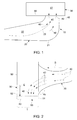
FIG. 1 is a schematic view of an exhaust diffuser and an exhaust plenum; -
FIG. 2 is a side view of the exhaust diffuser and the exhaust plenum ofFIG. 1 ; -
FIG. 3 is an enlarged perspective view of a wall of the exhaust plenum; -
FIGS. 4-7 are cross-sectional views of a flow splitter; and -
FIG. 8 is a plan view of the fluid volume constrained within an exit of the exhaust diffuser and the exhaust plenum. - The detailed description explains embodiments of the invention, together with advantages and features, by way of example with reference to the drawings.
- With reference to
FIG. 1 , anapparatus 10 is provided and includes an exhaust diffuser 20 (hereinafter referred to as a "diffuser 20") and an exhaust plenum 30 (hereinafter referred to as a plenum 30). Thediffuser 20 includes aperipheral wall 21 defining adiffuser interior 22 through which aflow path 23 extends.Fluid 40 flows along theflow path 23 towarddiffuser exit 45 defined proximate to theplenum 30. Theplenum 30 is fluidly coupled to thediffuser 20 at a location that is proximate to thediffuser exit 45 and includes aplenum wall 50 that is formed to defme aplenum interior 51, which is receptive of thefluid 40 being exhausted from thediffuser exit 45. - With reference to
FIGS. 2 ,3 and 4 , theplenum wall 50 includes first and secondopposing walls diffuser 20 being fluidly coupled to the firstopposing wall 51, and anintermediate wall 53 extending between the first and secondopposing walls intermediate wall 53 includeswall section 60 toward which theexhausted fluid 40 is directed upon exiting thediffuser 20. Thewall section 60 includesfirst sections 61,second sections 62 interposed between thefirst sections 61 and aflow splitter 70 interposed between thesecond sections 62. Asecond section plane 622 of thesecond sections 62 is recessed from afirst section plane 611 of thefirst sections 61 and theflow splitter 70 protrudes from thesecond section plane 622 toward thefirst section plane 611. - As shown in
FIGS. 2 ,3 and 4 , thewall section 60 includes a bottom-most portion of theintermediate wall 53 relative to a gravitation direction which may be similar in orientation to a partial exhaust direction, E, of theexhausted fluid 40. Thesecond section plane 622 is recessed from thefirst section plane 611 in the exhaust direction, E, and theflow splitter 70 protrudes from thesecond section plane 622 toward thefirst section plane 611 in a direction opposite to the exhaust direction, E. Theflow splitter 70 may include aflow splitter body 71 and may have a height length, LF, which is generally shorter than a depth length of the recess, LR, such that anuppermost tip 72 of theflow splitter 70 is recessed from thefirst section plane 611 in the exhaust direction, E. - With the configuration described above, the
flow splitter 70 may include a radial extension of thewall section 60 that extends toward thediffuser 20. Theflow splitter 70 may be integrally connected to thewall section 60 or otherwise disposed at thewall section 60 at a predefined position between thesecond sections 62. Theflow splitter 70 may be formed as a single component or multiple components and may span a thickness, T, of thewall section 60 as defined from the firstopposing wall 51 to the secondopposing wall 52. - With reference to
FIGS. 4-7 , theflow splitter 70 may have various cross-sectional shapes including, but not limited to, a frusto-conical shape as inFIG. 4 , a conical or pointed shape as inFIG. 5 , a rectangular or square shape as inFIG. 6 and/or a trapezoidal shape as inFIG. 7 . - With reference to
FIGS. 2 and8 , a longitudinal axis of theflow splitter 70 may be oriented to be substantially parallel with a predominant direction, D, of fluid flow through thediffuser 20. Here, a cross-section of theflow splitter 70 is shown as having a rectangular shape but, in accordance withFIGS. 4-7 , the cross-section of the flow splitter may have a frusto-conical shape, a substantially conical or pointed shape, a trapezoidal shape and/or other similar shapes. In this way, the flow splitter 70 directs theexhausted fluid 40 to flow in lateral directions, L1 and L2, which are oriented substantially transversely with respect to the predominant direction, D, of the fluid flow through thediffuser 20. - As such, the flow splitter 70 substantially prevents
fluid 40 flow reversal by directing flow to recirculate near theflow splitter 70. This relatively localized recirculation leads to a development of a false wall that may enhance a diffusing passage. - In accordance with still further embodiments of the invention, it is to be understood that the
flow splitter 70 need not be positioned on or coupled to theintermediate wall 53. In fact, theflow splitter 70 may be positioned on or coupled to either of the firstopposing wall 51 or the secondopposing wall 52 alone or in combination with a further coupling to another one or more of the walls. It is further to be understood that theexhausted fluid 40 is at least partially exhausted toward the first and the secondopposing walls - While the invention has been described in detail in connection with only a limited number of embodiments, it should be readily understood that the invention is not limited to such disclosed embodiments. Rather, the invention can be modified to incorporate any number of variations, alterations, substitutions or equivalent arrangements not heretofore described, but which are commensurate with the spirit and scope of the invention. Additionally, while various embodiments of the invention have been described, it is to be understood that aspects of the invention may include only some of the described embodiments. Accordingly, the invention is not to be seen as limited by the foregoing description, but is only limited by the scope of the appended claims.
- Various aspects and embodiments of the present invention are defmed by the following numbered clauses:
- 1. An apparatus, comprising:
- a plenum into which a fluid is exhausted, the plenum including a wall toward which the exhausted fluid is directed,
- the wall including first sections, second sections interposed between the first sections and a flow splitter interposed between the second sections, and
- a plane of the second sections being recessed from a plane of the first sections and the flow splitter protruding from the plane of the second sections.
- 2. The apparatus according to clause 1, wherein the wall comprises a bottom-most wall of the plenum relative to a gravitation direction.
- 3. The apparatus according to clause 1, wherein the plane of the second sections is recessed from the plane of the first sections in an exhaust direction of the exhausted fluid, the flow splitter protrudes from the plane of the second sections toward the plane of the first sections and an uppermost tip of the flow splitter is recessed from the plane of the first sections in the exhaust direction.
- 4. The apparatus according to clause 1, wherein the flow splitter is integrally connected to the wall.
- 5. The apparatus according to clause 1, wherein the flow splitter is disposed at a predefined position of the wall between the second sections.
- 6. The apparatus according to clause 1, wherein the flow splitter spans a thickness of the wall.
- 7. The apparatus according to clause 1, wherein a cross-section of the flow splitter has any one of a frusto-conical shape, a conical or po inted shape, a rectangular or square shape and a trapezoidal shape.
- 8. An apparatus, comprising:
- a diffuser through which fluid flows; and
- a plenum fluidly coupled to the diffuser into which the fluid is exhausted from the diffuser, the plenum including a wall toward which the exhausted fluid is directed, the wall including first sections, second sections interposed between the first sections and a flow splitter interposed between the second sections, and
- a plane of the second sections being recessed from a plane of the first sections and the flow splitter protruding from the plane of the second sections.
- 9. The apparatus according to clause 8, wherein the wall comprises a bottom-most wall of the plenum relative to a gravitation direction.
- 10. The apparatus according to clause 8, wherein the plane of the second sections is recessed from the plane of the first sections in an exhaust direction of the exhausted fluid, the flow splitter protrudes from the plane of the second sections toward the plane of the first sections and an uppermost tip of the flow splitter is recessed from the plane of the first sections in the exhaust direction.
- 11. The apparatus according to clause 8, wherein the flow splitter comprises a radial extension of the wall toward the diffuser.
- 12. The apparatus according to clause 8, wherein the flow splitter is integrally connected to the wall.
- 13. The apparatus according to clause 8, wherein the flow splitter is disposed at a predefined position of the wall between the second sections.
- 14. The apparatus according to clause 8, wherein the flow splitter spans a thickness of the wall.
- 15. The apparatus according to clause 8, wherein a longitudinal axis of the flow splitter is substantially parallel with a predominant direction of fluid flow through the diffuser.
- 16. The apparatus according to clause 8, wherein a cross-section of the flow splitter has any one of a frusto-conical shape, a conical or pointed shape, a rectangular or square shape and a trapezoidal shape.
- 17. The apparatus according to clause 8, wherein the flow splitter directs the exhausted fluid to flow in lateral directions oriented transversely to a predominant direction of fluid flow through the diffuser.
- 18. An apparatus, comprising:
- a diffuser including a peripheral wall defining a flow path along which fluid flows toward a diffuser exit; and
- a plenum fluidly coupled to the diffuser into which the fluid is exhausted from the diffuser exit, the plenum including a wall toward which the exhausted fluid is directed,
- the wall including first sections, second sections interposed between the first sections and a flow splitter interposed between the second sections, and
- a plane of the second sections being recessed from a plane of the first sections and the flow splitter protruding from the plane of the second sections toward the plane of the first sections.
- 19. The apparatus according to clause 18, wherein a cross-section of the flow splitter has any one of a frusto-conical shape, a conical or pointed shape, a rectangular or square shape and a trapezoidal shape.
- 20. The apparatus according to clause 18, wherein the flow splitter directs the exhausted fluid to flow in lateral directions oriented transversely to a predominant direction of fluid flow through the diffuser.
Claims (7)
- An apparatus (10), comprising:a plenum (30) into which a fluid (40) is exhausted, the plenum (30) including a wall (53) toward which the exhausted fluid is directed,the wall (53) including first sections (61), second sections (62) interposed between the first sections (61) and a flow splitter (70) interposed between the second sections (62), anda plane of the second sections (62) being recessed from a plane of the first sections (61) and the flow splitter (70) protruding from the plane of the second sections (62).
- The apparatus (10) according to claim 1, wherein the wall (53) comprises a bottom-most wall (53) of the plenum (30) relative to a gravitation direction.
- The apparatus (10) according to claim 1 or 2, wherein the plane of the second sections (62) is recessed from the plane of the first sections (61) in an exhaust direction of the exhausted fluid, the flow splitter (70) protrudes from the plane of the second sections (62) toward the plane of the first sections (61) and an uppermost tip 72 of the flow splitter (70) is recessed from the plane of the first sections (61) in the exhaust direction.
- The apparatus (10) according to any of the preceding claims, wherein the flow splitter (70) is integrally connected to the wall (53).
- The apparatus (10) according to any of the preceding claims, wherein the flow splitter (70) is disposed at a predefined position of the wall (53) between the second sections (62).
- The apparatus (10) according to any of the preceding claims, wherein the flow splitter (70) spans a thickness of the wall (53).
- The apparatus (10) according to any of the preceding claims, wherein a cross-section of the flow splitter (70) has any one of a frusto-conical shape, a conical or pointed shape, a rectangular or square shape and a trapezoidal shape.
Applications Claiming Priority (1)
| Application Number | Priority Date | Filing Date | Title |
|---|---|---|---|
| US12/841,668 US8418717B2 (en) | 2010-07-22 | 2010-07-22 | Exhaust plenum flow splitter |
Publications (3)
| Publication Number | Publication Date |
|---|---|
| EP2410135A2 true EP2410135A2 (en) | 2012-01-25 |
| EP2410135A3 EP2410135A3 (en) | 2014-11-12 |
| EP2410135B1 EP2410135B1 (en) | 2017-10-11 |
Family
ID=44786171
Family Applications (1)
| Application Number | Title | Priority Date | Filing Date |
|---|---|---|---|
| EP11173929.8A Not-in-force EP2410135B1 (en) | 2010-07-22 | 2011-07-14 | Exhaust plenum flow splitter |
Country Status (3)
| Country | Link |
|---|---|
| US (1) | US8418717B2 (en) |
| EP (1) | EP2410135B1 (en) |
| CN (1) | CN102400722B (en) |
Families Citing this family (2)
| Publication number | Priority date | Publication date | Assignee | Title |
|---|---|---|---|---|
| US8757969B2 (en) | 2010-09-15 | 2014-06-24 | General Electric Company | Turbine exhaust plenum |
| US10113484B2 (en) | 2015-12-21 | 2018-10-30 | General Electric Company | High pressure exhaust muffling device with multiple sources |
Family Cites Families (19)
| Publication number | Priority date | Publication date | Assignee | Title |
|---|---|---|---|---|
| GB105933A (en) * | 1916-02-04 | 1917-05-04 | Karl Baumann | Improvements in or relating to Steam Turbines. |
| US2565674A (en) * | 1947-07-10 | 1951-08-28 | Willard Storage Battery Co | Storage battery |
| US2620230A (en) * | 1947-10-04 | 1952-12-02 | Fmc Corp | Insecticide spreading machine |
| US3470914A (en) * | 1967-01-04 | 1969-10-07 | Du Pont | Flow inversion apparatus and process |
| US3864938A (en) * | 1973-09-25 | 1975-02-11 | Carrier Corp | Refrigerant flow control device |
| SE409589C (en) * | 1977-12-22 | 1984-04-09 | Soederstroem Gert | SEAL |
| JPS58142483U (en) * | 1982-03-20 | 1983-09-26 | 住友金属工業株式会社 | flow divider |
| US5503182A (en) * | 1994-12-06 | 1996-04-02 | Huang; Fu-Shiang | Air pressure adjusting module balancing value and its chamber structure |
| US20100230508A1 (en) * | 2007-05-31 | 2010-09-16 | Petrovich Svetozar B | God device genres cadres |
| US6035704A (en) * | 1998-06-12 | 2000-03-14 | Newman; Michael R. | Apparatus for the enhancement of water quality in a subterranean pressurized water distribution system |
| GB0000279D0 (en) * | 2000-01-08 | 2000-03-01 | Wood Group Pressure Control Li | Pipe choke |
| DE10003517C2 (en) * | 2000-01-27 | 2001-11-22 | Siemens Ag | Operating building for a plant and method for operating an operating building |
| US6419448B1 (en) * | 2000-03-20 | 2002-07-16 | Jerzy A. Owczarek | Flow by-pass system for use in steam turbine exhaust hoods |
| SE525007C2 (en) * | 2003-03-17 | 2004-11-09 | Vattenfall Ab | Method and apparatus for braking and disintegrating a fluid plug in a conduit channel |
| US7357618B2 (en) * | 2005-05-25 | 2008-04-15 | General Electric Company | Flow splitter for steam turbines |
| US7549442B2 (en) * | 2007-02-01 | 2009-06-23 | Brown And Caldwell | Intake for vertical wet pit pump |
| US8066935B2 (en) * | 2007-12-14 | 2011-11-29 | The Harrison Steel Castings Company | Turbulence inhibiting impact well for submerged shroud or sprue poured castings |
| US8322126B2 (en) | 2008-05-23 | 2012-12-04 | Rolls-Royce North American Technologies, Inc. | Gas turbine exhaust assembly |
| DE202009012826U1 (en) * | 2009-09-24 | 2011-02-10 | Viega Gmbh & Co. Kg | Drain, especially for floor-level showers |
-
2010
- 2010-07-22 US US12/841,668 patent/US8418717B2/en not_active Expired - Fee Related
-
2011
- 2011-07-14 EP EP11173929.8A patent/EP2410135B1/en not_active Not-in-force
- 2011-07-22 CN CN201110218575.7A patent/CN102400722B/en not_active Expired - Fee Related
Non-Patent Citations (1)
| Title |
|---|
| None |
Also Published As
| Publication number | Publication date |
|---|---|
| EP2410135A3 (en) | 2014-11-12 |
| CN102400722B (en) | 2015-11-25 |
| EP2410135B1 (en) | 2017-10-11 |
| CN102400722A (en) | 2012-04-04 |
| US8418717B2 (en) | 2013-04-16 |
| US20120018015A1 (en) | 2012-01-26 |
Similar Documents
| Publication | Publication Date | Title |
|---|---|---|
| US20140151143A1 (en) | Construction machine | |
| EP3165272B1 (en) | Exhaust gas processing apparatus | |
| US20090000286A1 (en) | Assembly for fitting together exhaust pipes in multi-cylinder engine | |
| JP5626597B2 (en) | Intake manifold | |
| EP2151627A3 (en) | Turbomachine Injection Nozzle Including a Coolant Delivery System | |
| CN104487717B (en) | A device that produces a swirling flow of fluid | |
| US20070266989A1 (en) | Intake accelerator for an engine | |
| EP1818504A3 (en) | Material having internal cooling passage and method for cooling material having internal cooling passage | |
| EP2410135A2 (en) | Exhaust plenum flow splitter | |
| JP6496634B2 (en) | Exhaust structure of construction machinery | |
| JP2016173041A (en) | Engine exhaust system | |
| CN104976154B (en) | The shell of cfentrifugal blower | |
| CN106662283A (en) | fluid delivery tube | |
| EP1726811A3 (en) | System and method for cooling lateral edge regions of a divergent seal of an axisymmetric nozzle | |
| JP2008088887A (en) | Common rail and its manufacturing method | |
| US8727738B2 (en) | Jet pump assembly having increased entrainment flow | |
| JP2009078648A (en) | Fuel vapor outflow device | |
| CN109779730B (en) | Exhaust gas guide device for construction machine | |
| CN105587453A (en) | Fuel injection valve | |
| JP6189351B2 (en) | Channel structure | |
| JP5855495B2 (en) | Intake manifold | |
| JP2022061056A (en) | Reservoir tank | |
| JP5078558B2 (en) | Intake manifold and internal combustion engine | |
| US20190113164A1 (en) | Pipe unit coupling structure | |
| JP2013108367A (en) | Muffler |
Legal Events
| Date | Code | Title | Description |
|---|---|---|---|
| AK | Designated contracting states |
Kind code of ref document: A2 Designated state(s): AL AT BE BG CH CY CZ DE DK EE ES FI FR GB GR HR HU IE IS IT LI LT LU LV MC MK MT NL NO PL PT RO RS SE SI SK SM TR |
|
| AX | Request for extension of the european patent |
Extension state: BA ME |
|
| PUAI | Public reference made under article 153(3) epc to a published international application that has entered the european phase |
Free format text: ORIGINAL CODE: 0009012 |
|
| PUAL | Search report despatched |
Free format text: ORIGINAL CODE: 0009013 |
|
| AK | Designated contracting states |
Kind code of ref document: A3 Designated state(s): AL AT BE BG CH CY CZ DE DK EE ES FI FR GB GR HR HU IE IS IT LI LT LU LV MC MK MT NL NO PL PT RO RS SE SI SK SM TR |
|
| AX | Request for extension of the european patent |
Extension state: BA ME |
|
| RIC1 | Information provided on ipc code assigned before grant |
Ipc: F01D 25/30 20060101ALI20141003BHEP Ipc: F01D 25/00 20060101AFI20141003BHEP |
|
| 17P | Request for examination filed |
Effective date: 20150512 |
|
| RBV | Designated contracting states (corrected) |
Designated state(s): AL AT BE BG CH CY CZ DE DK EE ES FI FR GB GR HR HU IE IS IT LI LT LU LV MC MK MT NL NO PL PT RO RS SE SI SK SM TR |
|
| GRAP | Despatch of communication of intention to grant a patent |
Free format text: ORIGINAL CODE: EPIDOSNIGR1 |
|
| STAA | Information on the status of an ep patent application or granted ep patent |
Free format text: STATUS: GRANT OF PATENT IS INTENDED |
|
| INTG | Intention to grant announced |
Effective date: 20170523 |
|
| GRAS | Grant fee paid |
Free format text: ORIGINAL CODE: EPIDOSNIGR3 |
|
| GRAA | (expected) grant |
Free format text: ORIGINAL CODE: 0009210 |
|
| STAA | Information on the status of an ep patent application or granted ep patent |
Free format text: STATUS: THE PATENT HAS BEEN GRANTED |
|
| AK | Designated contracting states |
Kind code of ref document: B1 Designated state(s): AL AT BE BG CH CY CZ DE DK EE ES FI FR GB GR HR HU IE IS IT LI LT LU LV MC MK MT NL NO PL PT RO RS SE SI SK SM TR |
|
| REG | Reference to a national code |
Ref country code: GB Ref legal event code: FG4D |
|
| REG | Reference to a national code |
Ref country code: CH Ref legal event code: EP |
|
| REG | Reference to a national code |
Ref country code: IE Ref legal event code: FG4D |
|
| REG | Reference to a national code |
Ref country code: AT Ref legal event code: REF Ref document number: 936244 Country of ref document: AT Kind code of ref document: T Effective date: 20171115 |
|
| REG | Reference to a national code |
Ref country code: DE Ref legal event code: R096 Ref document number: 602011042241 Country of ref document: DE |
|
| REG | Reference to a national code |
Ref country code: NL Ref legal event code: MP Effective date: 20171011 |
|
| REG | Reference to a national code |
Ref country code: LT Ref legal event code: MG4D |
|
| REG | Reference to a national code |
Ref country code: AT Ref legal event code: MK05 Ref document number: 936244 Country of ref document: AT Kind code of ref document: T Effective date: 20171011 |
|
| PG25 | Lapsed in a contracting state [announced via postgrant information from national office to epo] |
Ref country code: NL Free format text: LAPSE BECAUSE OF FAILURE TO SUBMIT A TRANSLATION OF THE DESCRIPTION OR TO PAY THE FEE WITHIN THE PRESCRIBED TIME-LIMIT Effective date: 20171011 |
|
| PG25 | Lapsed in a contracting state [announced via postgrant information from national office to epo] |
Ref country code: ES Free format text: LAPSE BECAUSE OF FAILURE TO SUBMIT A TRANSLATION OF THE DESCRIPTION OR TO PAY THE FEE WITHIN THE PRESCRIBED TIME-LIMIT Effective date: 20171011 Ref country code: SE Free format text: LAPSE BECAUSE OF FAILURE TO SUBMIT A TRANSLATION OF THE DESCRIPTION OR TO PAY THE FEE WITHIN THE PRESCRIBED TIME-LIMIT Effective date: 20171011 Ref country code: FI Free format text: LAPSE BECAUSE OF FAILURE TO SUBMIT A TRANSLATION OF THE DESCRIPTION OR TO PAY THE FEE WITHIN THE PRESCRIBED TIME-LIMIT Effective date: 20171011 Ref country code: LT Free format text: LAPSE BECAUSE OF FAILURE TO SUBMIT A TRANSLATION OF THE DESCRIPTION OR TO PAY THE FEE WITHIN THE PRESCRIBED TIME-LIMIT Effective date: 20171011 Ref country code: NO Free format text: LAPSE BECAUSE OF FAILURE TO SUBMIT A TRANSLATION OF THE DESCRIPTION OR TO PAY THE FEE WITHIN THE PRESCRIBED TIME-LIMIT Effective date: 20180111 |
|
| PG25 | Lapsed in a contracting state [announced via postgrant information from national office to epo] |
Ref country code: HR Free format text: LAPSE BECAUSE OF FAILURE TO SUBMIT A TRANSLATION OF THE DESCRIPTION OR TO PAY THE FEE WITHIN THE PRESCRIBED TIME-LIMIT Effective date: 20171011 Ref country code: AT Free format text: LAPSE BECAUSE OF FAILURE TO SUBMIT A TRANSLATION OF THE DESCRIPTION OR TO PAY THE FEE WITHIN THE PRESCRIBED TIME-LIMIT Effective date: 20171011 Ref country code: LV Free format text: LAPSE BECAUSE OF FAILURE TO SUBMIT A TRANSLATION OF THE DESCRIPTION OR TO PAY THE FEE WITHIN THE PRESCRIBED TIME-LIMIT Effective date: 20171011 Ref country code: GR Free format text: LAPSE BECAUSE OF FAILURE TO SUBMIT A TRANSLATION OF THE DESCRIPTION OR TO PAY THE FEE WITHIN THE PRESCRIBED TIME-LIMIT Effective date: 20180112 Ref country code: RS Free format text: LAPSE BECAUSE OF FAILURE TO SUBMIT A TRANSLATION OF THE DESCRIPTION OR TO PAY THE FEE WITHIN THE PRESCRIBED TIME-LIMIT Effective date: 20171011 Ref country code: BG Free format text: LAPSE BECAUSE OF FAILURE TO SUBMIT A TRANSLATION OF THE DESCRIPTION OR TO PAY THE FEE WITHIN THE PRESCRIBED TIME-LIMIT Effective date: 20180111 Ref country code: IS Free format text: LAPSE BECAUSE OF FAILURE TO SUBMIT A TRANSLATION OF THE DESCRIPTION OR TO PAY THE FEE WITHIN THE PRESCRIBED TIME-LIMIT Effective date: 20180211 |
|
| REG | Reference to a national code |
Ref country code: DE Ref legal event code: R097 Ref document number: 602011042241 Country of ref document: DE |
|
| PG25 | Lapsed in a contracting state [announced via postgrant information from national office to epo] |
Ref country code: DK Free format text: LAPSE BECAUSE OF FAILURE TO SUBMIT A TRANSLATION OF THE DESCRIPTION OR TO PAY THE FEE WITHIN THE PRESCRIBED TIME-LIMIT Effective date: 20171011 Ref country code: SK Free format text: LAPSE BECAUSE OF FAILURE TO SUBMIT A TRANSLATION OF THE DESCRIPTION OR TO PAY THE FEE WITHIN THE PRESCRIBED TIME-LIMIT Effective date: 20171011 Ref country code: EE Free format text: LAPSE BECAUSE OF FAILURE TO SUBMIT A TRANSLATION OF THE DESCRIPTION OR TO PAY THE FEE WITHIN THE PRESCRIBED TIME-LIMIT Effective date: 20171011 Ref country code: CZ Free format text: LAPSE BECAUSE OF FAILURE TO SUBMIT A TRANSLATION OF THE DESCRIPTION OR TO PAY THE FEE WITHIN THE PRESCRIBED TIME-LIMIT Effective date: 20171011 |
|
| PLBE | No opposition filed within time limit |
Free format text: ORIGINAL CODE: 0009261 |
|
| STAA | Information on the status of an ep patent application or granted ep patent |
Free format text: STATUS: NO OPPOSITION FILED WITHIN TIME LIMIT |
|
| PG25 | Lapsed in a contracting state [announced via postgrant information from national office to epo] |
Ref country code: IT Free format text: LAPSE BECAUSE OF FAILURE TO SUBMIT A TRANSLATION OF THE DESCRIPTION OR TO PAY THE FEE WITHIN THE PRESCRIBED TIME-LIMIT Effective date: 20171011 Ref country code: PL Free format text: LAPSE BECAUSE OF FAILURE TO SUBMIT A TRANSLATION OF THE DESCRIPTION OR TO PAY THE FEE WITHIN THE PRESCRIBED TIME-LIMIT Effective date: 20171011 Ref country code: SM Free format text: LAPSE BECAUSE OF FAILURE TO SUBMIT A TRANSLATION OF THE DESCRIPTION OR TO PAY THE FEE WITHIN THE PRESCRIBED TIME-LIMIT Effective date: 20171011 Ref country code: RO Free format text: LAPSE BECAUSE OF FAILURE TO SUBMIT A TRANSLATION OF THE DESCRIPTION OR TO PAY THE FEE WITHIN THE PRESCRIBED TIME-LIMIT Effective date: 20171011 |
|
| 26N | No opposition filed |
Effective date: 20180712 |
|
| PG25 | Lapsed in a contracting state [announced via postgrant information from national office to epo] |
Ref country code: SI Free format text: LAPSE BECAUSE OF FAILURE TO SUBMIT A TRANSLATION OF THE DESCRIPTION OR TO PAY THE FEE WITHIN THE PRESCRIBED TIME-LIMIT Effective date: 20171011 |
|
| REG | Reference to a national code |
Ref country code: DE Ref legal event code: R119 Ref document number: 602011042241 Country of ref document: DE |
|
| REG | Reference to a national code |
Ref country code: CH Ref legal event code: PL |
|
| GBPC | Gb: european patent ceased through non-payment of renewal fee |
Effective date: 20180714 |
|
| PG25 | Lapsed in a contracting state [announced via postgrant information from national office to epo] |
Ref country code: LU Free format text: LAPSE BECAUSE OF NON-PAYMENT OF DUE FEES Effective date: 20180714 Ref country code: MC Free format text: LAPSE BECAUSE OF FAILURE TO SUBMIT A TRANSLATION OF THE DESCRIPTION OR TO PAY THE FEE WITHIN THE PRESCRIBED TIME-LIMIT Effective date: 20171011 |
|
| REG | Reference to a national code |
Ref country code: BE Ref legal event code: MM Effective date: 20180731 |
|
| REG | Reference to a national code |
Ref country code: IE Ref legal event code: MM4A |
|
| PG25 | Lapsed in a contracting state [announced via postgrant information from national office to epo] |
Ref country code: GB Free format text: LAPSE BECAUSE OF NON-PAYMENT OF DUE FEES Effective date: 20180714 Ref country code: IE Free format text: LAPSE BECAUSE OF NON-PAYMENT OF DUE FEES Effective date: 20180714 Ref country code: CH Free format text: LAPSE BECAUSE OF NON-PAYMENT OF DUE FEES Effective date: 20180731 Ref country code: DE Free format text: LAPSE BECAUSE OF NON-PAYMENT OF DUE FEES Effective date: 20190201 Ref country code: FR Free format text: LAPSE BECAUSE OF NON-PAYMENT OF DUE FEES Effective date: 20180731 Ref country code: LI Free format text: LAPSE BECAUSE OF NON-PAYMENT OF DUE FEES Effective date: 20180731 |
|
| PG25 | Lapsed in a contracting state [announced via postgrant information from national office to epo] |
Ref country code: BE Free format text: LAPSE BECAUSE OF NON-PAYMENT OF DUE FEES Effective date: 20180731 |
|
| PG25 | Lapsed in a contracting state [announced via postgrant information from national office to epo] |
Ref country code: MT Free format text: LAPSE BECAUSE OF NON-PAYMENT OF DUE FEES Effective date: 20180714 |
|
| PG25 | Lapsed in a contracting state [announced via postgrant information from national office to epo] |
Ref country code: TR Free format text: LAPSE BECAUSE OF FAILURE TO SUBMIT A TRANSLATION OF THE DESCRIPTION OR TO PAY THE FEE WITHIN THE PRESCRIBED TIME-LIMIT Effective date: 20171011 |
|
| PG25 | Lapsed in a contracting state [announced via postgrant information from national office to epo] |
Ref country code: PT Free format text: LAPSE BECAUSE OF FAILURE TO SUBMIT A TRANSLATION OF THE DESCRIPTION OR TO PAY THE FEE WITHIN THE PRESCRIBED TIME-LIMIT Effective date: 20171011 Ref country code: HU Free format text: LAPSE BECAUSE OF FAILURE TO SUBMIT A TRANSLATION OF THE DESCRIPTION OR TO PAY THE FEE WITHIN THE PRESCRIBED TIME-LIMIT; INVALID AB INITIO Effective date: 20110714 |
|
| PG25 | Lapsed in a contracting state [announced via postgrant information from national office to epo] |
Ref country code: MK Free format text: LAPSE BECAUSE OF NON-PAYMENT OF DUE FEES Effective date: 20171011 Ref country code: CY Free format text: LAPSE BECAUSE OF FAILURE TO SUBMIT A TRANSLATION OF THE DESCRIPTION OR TO PAY THE FEE WITHIN THE PRESCRIBED TIME-LIMIT Effective date: 20171011 |
|
| PG25 | Lapsed in a contracting state [announced via postgrant information from national office to epo] |
Ref country code: AL Free format text: LAPSE BECAUSE OF FAILURE TO SUBMIT A TRANSLATION OF THE DESCRIPTION OR TO PAY THE FEE WITHIN THE PRESCRIBED TIME-LIMIT Effective date: 20171011 |