EP2409901A1 - Fifth wheel slider assembly - Google Patents
Fifth wheel slider assembly Download PDFInfo
- Publication number
- EP2409901A1 EP2409901A1 EP11185395A EP11185395A EP2409901A1 EP 2409901 A1 EP2409901 A1 EP 2409901A1 EP 11185395 A EP11185395 A EP 11185395A EP 11185395 A EP11185395 A EP 11185395A EP 2409901 A1 EP2409901 A1 EP 2409901A1
- Authority
- EP
- European Patent Office
- Prior art keywords
- slider assembly
- rack member
- assembly
- wheel
- wheel slider
- Prior art date
- Legal status (The legal status is an assumption and is not a legal conclusion. Google has not performed a legal analysis and makes no representation as to the accuracy of the status listed.)
- Withdrawn
Links
- 230000008878 coupling Effects 0.000 claims description 5
- 238000010168 coupling process Methods 0.000 claims description 5
- 238000005859 coupling reaction Methods 0.000 claims description 5
- 238000004519 manufacturing process Methods 0.000 description 8
- 238000013461 design Methods 0.000 description 7
- 238000000034 method Methods 0.000 description 6
- 238000003466 welding Methods 0.000 description 6
- 230000000712 assembly Effects 0.000 description 5
- 238000000429 assembly Methods 0.000 description 5
- 238000009420 retrofitting Methods 0.000 description 3
- 229910000831 Steel Inorganic materials 0.000 description 2
- 238000004891 communication Methods 0.000 description 2
- 239000010959 steel Substances 0.000 description 2
- 230000001133 acceleration Effects 0.000 description 1
- 238000004140 cleaning Methods 0.000 description 1
- 238000010276 construction Methods 0.000 description 1
- 230000003247 decreasing effect Effects 0.000 description 1
- 238000012986 modification Methods 0.000 description 1
- 230000004048 modification Effects 0.000 description 1
- 230000002093 peripheral effect Effects 0.000 description 1
- 238000012546 transfer Methods 0.000 description 1
Images



Classifications
-
- B—PERFORMING OPERATIONS; TRANSPORTING
- B62—LAND VEHICLES FOR TRAVELLING OTHERWISE THAN ON RAILS
- B62D—MOTOR VEHICLES; TRAILERS
- B62D53/00—Tractor-trailer combinations; Road trains
- B62D53/04—Tractor-trailer combinations; Road trains comprising a vehicle carrying an essential part of the other vehicle's load by having supporting means for the front or rear part of the other vehicle
- B62D53/08—Fifth wheel traction couplings
- B62D53/0807—Fifth wheel traction couplings adjustable coupling saddles mounted on sub-frames; Mounting plates therefor
- B62D53/0814—Fifth wheel traction couplings adjustable coupling saddles mounted on sub-frames; Mounting plates therefor with adjustment of the clearance between the tractor or the trailer
Definitions
- the present invention relates to fifth wheel coupling assemblies, and in particular to a slider assembly for adjustably supporting a fifth wheel hitch assembly from a frame of an associated vehicle.
- the frames of the tractors, to which the fifth wheel assemblies are mounted typically comprise a pair of longitudinally-extending C-shaped channel members that are supported by the wheel and axle members of the vehicle.
- the channel members are laterally spaced apart from one another such that they provide a planar surface for resisting normal and twisting forces after the fifth wheel is secured thereupon and placed in operation, thereby transferring the payload of the trailer equally onto each of the channel members.
- the fifth wheel hitch assembly can be mounted on the truck frame in a number of various ways, such as by utilizing drop-over angle brackets or flat mounting plates.
- the drop-over method utilizes an L-shaped angle member which conforms and communicates with the top and vertical edges of each of the channels, having a long vertical leg securely fixed to an outboard vertical side of the associated channel, and a horizontal leg of the drop-over bracket that typically includes an arcuately-shaped mounting bracket which is welded thereon.
- the arcuate mounting bracket lies generally above the top horizontal leg of the C-shaped channel, and includes a horizontally-aligned bore for accepting a coupling cross pin which is in communication with the fifth wheel frame work.
- the fifth wheel frame work includes a flange on one or each peripheral edge that communicates with the arcuate mounting bracket, thereby allowing the flange ports on each flange to be horizontally aligned with the mounting bracket bore for pinning the fifth wheel to the drop-over angle mounting bracket and hence, to the tractor frame.
- the drop-over brackets transmit lateral inertial forces which are caused by curving and rocking of the fifth wheel into the frame, drop-over arrangements are best suited for resisting longitudinal forces and moments caused from acceleration, deceleration, as well as the downward forces acting on the ramps eccentric to the rear of the bracket pivot center during coupling.
- a flat plate mounting assembly includes a rectangular, planar plate of steel that is secured on top of each of the channel members, with the lateral sides of the plate extending slightly beyond each channel.
- a section of L-shaped angle typically referred to as the outboard angle, is used to support the plate directly below the overhang.
- the outboard angle member is also secured to the tractor channel and the flat mounting plate by securing a horizontal leg thereof to the bottom side of the mounting plate and securing a vertical leg thereof to the vertical wall of the associated channel. Similar arcuate mounting brackets to those discussed above are welded to the top of the mounting plate.
- the flat mounting plate method of attachment offers increased fatigue strength when compared to the drop-over mounting assembly because the lateral forces and moments that work upon the arcuate mounting bracket are first distributed throughout the entire flat plate surface area before they are distributed and transferred into the outboard angle member, thereby increasing the surface area over which the load is distributed.
- one significant disadvantage of the flat plat mounting arrangement is the use of a heavy steel plate adding to the weight and total cost of the overall assembly.
- typical fifth wheel assemblies that provide for slidable adjustment of the associated fifth wheel hitch plate with respect to the vehicle frame members require the use of separate stock members affixed to either a component of the fifth wheel assembly or the frame rails, in order to limit the travel of the fifth wheel hitch plate with respect to the vehicle frame rails, thereby adding to the costs associated with the manufacture of the fifth wheel hitch assembly.
- a fifth wheel hitch assembly is desired that reduces the number of components necessary to provide a slidable adjustment of an associated hitch plate with respect to supporting vehicle frame rails, while simultaneously providing for easy adjustment and replacement of worn or damaged components.
- the fifth wheel hitch assembly should further reduce the associated weight, reduce manufacturing costs by eliminating welding and other time consuming processes, provide a modular design that allows easy assembly and/or retrofitting, and allows for use with various truck frame designs without requiring significant reworking to either the hitch assembly of the truck frame.
- One aspect of the present invention is to provide a fifth wheel slider assembly that comprises at least one rack member having a first side and a second side and supportable above a vehicle frame, a hitch plate with a throat for receiving a kingpin of a trailer, and a pair of support brackets pivotally supporting the hitch plate and slidably abutting the first side of the at least one rack member.
- the fifth wheel slider assembly further includes a guide plate slidably abutting the second side of the at least one rack member and coupled to the pair of support brackets by a plurality of mechanical fasteners, and an engagement assembly releasably engaging the at least one rack member at incremental points along a length of the at least one rack member, thereby selectively positioning the hitch plate with respect to the at least one rack member.
- Another aspect of the present invention is to provide a fifth wheel slider assembly that comprises a pair of mounting brackets adapted to respectively mount to a pair of vehicle frame rails, a pair of rack members each having a first side and a second side and fixably secured to the mounting members, a hitch plate with a throat for receiving a kingpin of a trailer, and a pair of support brackets pivotally supporting the hitch plate.
- the fifth wheel slider assembly further includes a guide plate coupled with the support brackets by a plurality of mechanical fasteners such that the support brackets slidably abut the first sides of the rack members and the guide plate slidably abuts the second sides of the rack members, and an engagement assembly releasably engaging the rack members at incremental points along the length of the rack members, thereby selectively positioning the hitch plate with respect to the rack members.
- the present inventive fifth wheel hitch assembly reduces the number of components necessary to provide a slidable adjustment of an associated hitch plate with respect to supporting vehicle frame rails, while simultaneously providing for easy adjustment and replacement of worn or damaged components.
- the hitch assembly further reduces the associated weight, reduces manufacturing costs by eliminating welding and other time consuming processes, provides a modular design that allows easy assembly and/or retrofitting, allows for use with various truck frame designs without requiring significant reworking to either the hitch assembly of the truck frame, is economical to manufacture, and is particularly well adapted for the proposed use.
- the reference numeral 10 ( Figs. 1-4 ) generally designates a fifth wheel slider assembly embodying the present invention.
- the fifth wheel slider assembly is supported by a pair of vehicle frame rails 12 each having an outer vertical surface 14 and a top horizontal surface 16.
- the slider assembly 10 includes a pair of L-shaped angle brackets 18 each having a downwardly-extending vertical leg 20, an inwardly-extending horizontal leg 22, a first end 24 and a second end 26.
- a pair of laterally-extending structural support members 28 extend between the first ends 24 and the second ends 26 of the angle brackets 28, and are preferably fixedly secured thereto by welding, or the like.
- a pair of rack members 30 are fixedly secured by a weld to a horizontal leg 22 of a respective angle bracket 18.
- Each rack member 30 includes a plurality of notches 33 spaced incrementally along the length thereof.
- Each rack member 30 is provided with a T-shaped cross-sectional configuration having a top surface 32, an inner lip 34, and an outer lip 36.
- the slider assembly 10 further includes a pair of support brackets 38 slidably engaging and extending upwardly from a respective rack member 30.
- Each support bracket 38 includes a bushing housing 40 each having an aperture 41 extending therethrough, a base plate member 42 having a plurality of bolt receiving apertures 44 extending therethrough, and a plurality of support arms 46 extending between the bushing housing 40 and the base plate member 42.
- the base plate member 42 includes a longitudinally-extending outwardly and downwardly-curled guide edge 48 that slidably receives the outer lip 36 of the respective rack member 30 therein.
- An inwardly-extending lip 50 of the base plate member 42 includes the apertures 44 and is divided into a first portion 43 and a second portion 45, thereby defining a gap 47 therebetween.
- Each support bracket 38 includes a tilt stop member 52 extending upwardly from a support arm 46 and the base plate 42.
- the tilt stop member 52 is preferably integrally molded with the support bracket 38.
- a two-piece bushing 54 having a first portion 56 and a second portion 58 divided from one another at a center line 60. The division of the bushing 54 into the first portion 56 and the second portion 58 provides easier assembly and/or replacement due to the narrowing draft of the aperture 41, as well as reduces the need for cleaning the inner bore of the aperture 41 of cast parting lines formed during the manufacture of the support bracket 38.
- the slider assembly 10 further includes a hitch plate (not shown) that is pivotally coupled to the support brackets 38 by at least one pivot pin that extends into the bushing 54 in a manner as know in the art.
- the tilt stop members 52 limit the amount of tilt travel of the hitch plate with respect to the support brackets 38.
- the slider assembly 10 further includes a guide plate 62 having a first end 64, a second end 66, a centrally-located aperture 68 and a recessed side relief 70 functioning to reduce the overall weight of the guide plate 62.
- the first end 64 and second end 66 of the guide plate 62 are secured to the inner lip 50 of each base plate member 42 by a plurality of bolts 72.
- the guide plate 62 is configured such that the first end 64 and the second end 66 guide beneath the outer lip 36 of a respective rack member 30.
- the slider assembly 10 further includes an engagement assembly 74 including a pneumatic cylinder 76 having a housing 77 with a first end 78 and a rod 79 with a second end 80.
- the engagement assembly 74 further includes a first lock member 82 and a second lock member 83 each slidably received within the respective gap 47 and each having a plurality of engagement teeth 84 that are releasably engaged within the notches 33, thereby fixing the location of the support brackets 38 with respect to the rack members 30, and in turn fixing the location of the hitch plate with respect to the frame rails 12.
- At least one of the lock members 82, 83 includes an extended slot aperture 86 extending therethrough and that receives a mechanical fastener such as a bolt 88 securing the end 78, 80 to the lock member 82, 83 and allowing slight movement of the couple therebetween.
- a mechanical fastener such as a bolt 88 securing the end 78, 80 to the lock member 82, 83 and allowing slight movement of the couple therebetween.
- the slider assembly 10 further includes a stop member 90 located proximate the first end 64 and a stop member 91 located proximate the second end 66 of the guide plate 62 and secured thereto via the mechanical fasteners or bolts 72.
- Each of the stop members 90, 91 are juxtaposed across the guide plate 62 from one another and are positioned so as to abut the structural support members 28, thereby limiting the travel of the support brackets 38 with respect to the rack members 30, and as a result, the travel of the fifth wheel hitch plate with respect to the frame rails 12.
- the slider assembly 10 further includes a bulkhead bracket 92 having a guidepost 94 and a U-shaped clip 96 integrally formed with the guidepost 94 and that frictionally engages structural support member 28.
- the guide post 92 includes an aperture 98 extending therethrough, and through which hydraulic, electrical, and other communication/control lines extending between the trailer and towing vehicle are guided so as to reduce the possibility of damage thereto.
- the reference numeral 10a ( Figs. 5-7 ) generally designates another embodiment of the fifth wheel slider assembly. Since the slider assembly 10a is similar to the previously described slider assembly 10, similar parts appearing in Figs. 1-4 and Figs. 5-7 , respectively are represented by the same, corresponding reference numeral except for the suffix "a" in the numerals of the latter.
- the slider assembly 10a is similar to the slider assembly 10 with the main exception being the replacement of the L-shaped angle brackets 18 with planar outboard mounting plates 100, and the addition of mounting angles 101.
- the mounting plates 100 includes a plurality of apertures 102 spaced along the length thereof and that are adapted to receive mounting hardware such as bolts (not shown) therein to secure the mounting plates 100 and thereby the slider assembly 10a to the associated mounting angles 101.
- the mounting angles 101 extend longitudinally along the associated frame rails 12a and each include a first portion 103 and a second portion 105 extending orthogonally downward from the first portion 103 and secured to the associated frame rail 12a.
- the reference numeral 10b ( Figs. 8-11 ) generally designates another alternative embodiment of the fifth wheel slider assembly. Since the slider assembly 10b is similar to the previously described slider assembly 10, similar parts appearing in Figs. 1-4 and Figs. 8-11 , respectively are represented by the same, corresponding reference numeral except for the suffix "b" in the numerals of the latter.
- the slider assembly 10b is similar in construction to the slider assembly 10, with the main difference being the addition of a pair of over the frame mounting plates 104 welded to the top of the horizontal leg 22b of each angle bracket 18b. In the illustrated example, each over the frame mounting bracket 104 includes a plurality of notches 106 extending and spaced along the length of the mounting plate 104.
- the slider assembly 10b is secured to the associated frame rails 12b by welding the angle brackets 18b to the frame rails 12b.
- the present inventive fifth wheel hitch assembly reduces the number of components necessary to provide a slidable adjustment of an associated hitch plate with respect to supporting vehicle frame rails, while simultaneously providing for easy adjustment and replacement of worn or damaged components.
- the hitch assembly further reduces the associated weight, reduces manufacturing costs by eliminating welding and other time consuming processes, provides a modular design that allows easy assembly and/or retrofitting, allows for use with various truck frame designs without requiring significant reworking to either the hitch assembly of the truck frame, is economical to manufacture, and is particularly well adapted for the proposed use.
Landscapes
- Engineering & Computer Science (AREA)
- Chemical & Material Sciences (AREA)
- Combustion & Propulsion (AREA)
- Transportation (AREA)
- Mechanical Engineering (AREA)
- Body Structure For Vehicles (AREA)
- Automobile Manufacture Line, Endless Track Vehicle, Trailer (AREA)
Abstract
A fifth wheel slider assembly (10) comprises at least one rack member (30) having a first side and a second side and is supportable above a vehicle frame (12), a hitch plate with a throat for receiving a kingpin of a trailer, and a pair of support brackets (38) pivotally supporting the hitch plate and slidably abutting the first side of the at least one rack member (30). The slider assembly (10) further includes a guide plate (62) slidably abutting the second side of the at least one rack member (30) and coupled to the pair of support brackets (38) by a plurality of mechanical fasteners, and an engagement assembly releasably (74) engaging the at least one rack member (30) at incremental points along the length of the at least one rack member (30), thereby selectively positioning the hitch plate with respect to the at least one rack member (30).
Description
- This application claims the benefit of
U.S. Provisional Application No. 60/659,796, filed March 9, 2005 - The present invention relates to fifth wheel coupling assemblies, and in particular to a slider assembly for adjustably supporting a fifth wheel hitch assembly from a frame of an associated vehicle.
- Fifth wheel hitch assemblies are used in a wide variety of applications to releasably couple a trailer to an associated towing vehicle, including heavy-duty, over-the-road, tractors. The frames of the tractors, to which the fifth wheel assemblies are mounted, typically comprise a pair of longitudinally-extending C-shaped channel members that are supported by the wheel and axle members of the vehicle. The channel members are laterally spaced apart from one another such that they provide a planar surface for resisting normal and twisting forces after the fifth wheel is secured thereupon and placed in operation, thereby transferring the payload of the trailer equally onto each of the channel members. The fifth wheel hitch assembly can be mounted on the truck frame in a number of various ways, such as by utilizing drop-over angle brackets or flat mounting plates.
- The drop-over method utilizes an L-shaped angle member which conforms and communicates with the top and vertical edges of each of the channels, having a long vertical leg securely fixed to an outboard vertical side of the associated channel, and a horizontal leg of the drop-over bracket that typically includes an arcuately-shaped mounting bracket which is welded thereon. The arcuate mounting bracket lies generally above the top horizontal leg of the C-shaped channel, and includes a horizontally-aligned bore for accepting a coupling cross pin which is in communication with the fifth wheel frame work. Specifically, the fifth wheel frame work includes a flange on one or each peripheral edge that communicates with the arcuate mounting bracket, thereby allowing the flange ports on each flange to be horizontally aligned with the mounting bracket bore for pinning the fifth wheel to the drop-over angle mounting bracket and hence, to the tractor frame. Although the drop-over brackets transmit lateral inertial forces which are caused by curving and rocking of the fifth wheel into the frame, drop-over arrangements are best suited for resisting longitudinal forces and moments caused from acceleration, deceleration, as well as the downward forces acting on the ramps eccentric to the rear of the bracket pivot center during coupling.
- Alternatively, a flat plate mounting assembly includes a rectangular, planar plate of steel that is secured on top of each of the channel members, with the lateral sides of the plate extending slightly beyond each channel. In order to transfer loads from the plate to the frame, a section of L-shaped angle, typically referred to as the outboard angle, is used to support the plate directly below the overhang. The outboard angle member is also secured to the tractor channel and the flat mounting plate by securing a horizontal leg thereof to the bottom side of the mounting plate and securing a vertical leg thereof to the vertical wall of the associated channel. Similar arcuate mounting brackets to those discussed above are welded to the top of the mounting plate. The flat mounting plate method of attachment offers increased fatigue strength when compared to the drop-over mounting assembly because the lateral forces and moments that work upon the arcuate mounting bracket are first distributed throughout the entire flat plate surface area before they are distributed and transferred into the outboard angle member, thereby increasing the surface area over which the load is distributed. However, one significant disadvantage of the flat plat mounting arrangement is the use of a heavy steel plate adding to the weight and total cost of the overall assembly.
- Another significant disadvantage to each of these arrangements as discussed above is the significant welding the overall assemblies require, thereby increasing the manufacturing costs and decreasing the adjustability and variability of the overall assembly once installed. Still further, these designs typically extend below the upper surface of the associated vehicle frame or channel members, thereby requiring precise placement of laterally-extending structural frame members of either the truck frame or the fifth wheel slider assembly, and/or rerouting of associated electrical and hydraulic lines.
- Still further, typical fifth wheel assemblies that provide for slidable adjustment of the associated fifth wheel hitch plate with respect to the vehicle frame members require the use of separate stock members affixed to either a component of the fifth wheel assembly or the frame rails, in order to limit the travel of the fifth wheel hitch plate with respect to the vehicle frame rails, thereby adding to the costs associated with the manufacture of the fifth wheel hitch assembly.
- A fifth wheel hitch assembly is desired that reduces the number of components necessary to provide a slidable adjustment of an associated hitch plate with respect to supporting vehicle frame rails, while simultaneously providing for easy adjustment and replacement of worn or damaged components. The fifth wheel hitch assembly should further reduce the associated weight, reduce manufacturing costs by eliminating welding and other time consuming processes, provide a modular design that allows easy assembly and/or retrofitting, and allows for use with various truck frame designs without requiring significant reworking to either the hitch assembly of the truck frame.
- One aspect of the present invention is to provide a fifth wheel slider assembly that comprises at least one rack member having a first side and a second side and supportable above a vehicle frame, a hitch plate with a throat for receiving a kingpin of a trailer, and a pair of support brackets pivotally supporting the hitch plate and slidably abutting the first side of the at least one rack member. The fifth wheel slider assembly further includes a guide plate slidably abutting the second side of the at least one rack member and coupled to the pair of support brackets by a plurality of mechanical fasteners, and an engagement assembly releasably engaging the at least one rack member at incremental points along a length of the at least one rack member, thereby selectively positioning the hitch plate with respect to the at least one rack member.
- Another aspect of the present invention is to provide a fifth wheel slider assembly that comprises a pair of mounting brackets adapted to respectively mount to a pair of vehicle frame rails, a pair of rack members each having a first side and a second side and fixably secured to the mounting members, a hitch plate with a throat for receiving a kingpin of a trailer, and a pair of support brackets pivotally supporting the hitch plate. The fifth wheel slider assembly further includes a guide plate coupled with the support brackets by a plurality of mechanical fasteners such that the support brackets slidably abut the first sides of the rack members and the guide plate slidably abuts the second sides of the rack members, and an engagement assembly releasably engaging the rack members at incremental points along the length of the rack members, thereby selectively positioning the hitch plate with respect to the rack members.
- The present inventive fifth wheel hitch assembly reduces the number of components necessary to provide a slidable adjustment of an associated hitch plate with respect to supporting vehicle frame rails, while simultaneously providing for easy adjustment and replacement of worn or damaged components. The hitch assembly further reduces the associated weight, reduces manufacturing costs by eliminating welding and other time consuming processes, provides a modular design that allows easy assembly and/or retrofitting, allows for use with various truck frame designs without requiring significant reworking to either the hitch assembly of the truck frame, is economical to manufacture, and is particularly well adapted for the proposed use.
-
-
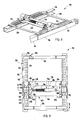
Fig. 1 is a top perspective view of a fifth wheel slider assembly embodying the present invention; -
Fig. 2 is a top plan view of the fifth wheel slider assembly; -
Fig. 3 is a partial cross-sectional view of the fifth wheel slider assembly, taken along the line III-III,Fig. 2 ; -
Fig. 4 is a side view of the fifth wheel slider assembly; -
Fig. 5 is a top perspective view of a first alternative embodiment of the fifth wheel slider assembly; -
Fig. 6 is a top plan view of the first alternative embodiment of the fifth wheel slider assembly; -
Fig. 7 is a partial cross-sectional end view of the first alternative embodiment of the fifth wheel slider assembly, taken along the line VII-VII,Fig. 6 ; -
Fig. 8 is a top perspective view of a second alternative embodiment of the fifth wheel slider assembly; -
Fig. 9 is a top plan view of the second alternative embodiment of the fifth wheel slider assembly; -
Fig. 10 is a partial cross-sectional view of the second alternative embodiment of the fifth wheel slider assembly, taken along the line X-X,Fig. 9 ; and -
Fig. 11 is a side view of the second alternative embodiment of the fifth wheel slider assembly. - For purposes of description herein, the terms "upper," "lower," "right," "left," "rear," "front," "vertical," "horizontal," and derivatives thereof shall relate to the invention as oriented in
Figs. 1 ,5 and8 . However, it is to be understood that the invention may assume various alternative orientations and step sequences, except where expressly specified to the contrary. It is also to be understood that the specific devices and processes illustrated in the attached drawings, and described in the following specification are exemplary embodiments of the inventive concepts defined in the appended claims. Hence, specific dimensions and other physical characteristics relating to the embodiments disclosed herein are not to be considered as limiting, unless the claims expressly state otherwise. - The reference numeral 10 (
Figs. 1-4 ) generally designates a fifth wheel slider assembly embodying the present invention. In the illustrated example, the fifth wheel slider assembly is supported by a pair ofvehicle frame rails 12 each having an outervertical surface 14 and a tophorizontal surface 16. Theslider assembly 10 includes a pair of L-shaped angle brackets 18 each having a downwardly-extendingvertical leg 20, an inwardly-extendinghorizontal leg 22, afirst end 24 and asecond end 26. A pair of laterally-extendingstructural support members 28 extend between thefirst ends 24 and thesecond ends 26 of theangle brackets 28, and are preferably fixedly secured thereto by welding, or the like. A pair ofrack members 30 are fixedly secured by a weld to ahorizontal leg 22 of arespective angle bracket 18. Eachrack member 30 includes a plurality ofnotches 33 spaced incrementally along the length thereof. Eachrack member 30 is provided with a T-shaped cross-sectional configuration having atop surface 32, aninner lip 34, and anouter lip 36. - The
slider assembly 10 further includes a pair ofsupport brackets 38 slidably engaging and extending upwardly from arespective rack member 30. Eachsupport bracket 38 includes abushing housing 40 each having anaperture 41 extending therethrough, abase plate member 42 having a plurality ofbolt receiving apertures 44 extending therethrough, and a plurality ofsupport arms 46 extending between thebushing housing 40 and thebase plate member 42. Thebase plate member 42 includes a longitudinally-extending outwardly and downwardly-curled guide edge 48 that slidably receives theouter lip 36 of therespective rack member 30 therein. An inwardly-extendinglip 50 of thebase plate member 42 includes theapertures 44 and is divided into afirst portion 43 and asecond portion 45, thereby defining agap 47 therebetween. Eachsupport bracket 38 includes atilt stop member 52 extending upwardly from asupport arm 46 and thebase plate 42. As in the illustrated example, thetilt stop member 52 is preferably integrally molded with thesupport bracket 38. In assembly, a two-piece bushing 54 having afirst portion 56 and asecond portion 58 divided from one another at acenter line 60. The division of thebushing 54 into thefirst portion 56 and thesecond portion 58 provides easier assembly and/or replacement due to the narrowing draft of theaperture 41, as well as reduces the need for cleaning the inner bore of theaperture 41 of cast parting lines formed during the manufacture of thesupport bracket 38. - The
slider assembly 10 further includes a hitch plate (not shown) that is pivotally coupled to thesupport brackets 38 by at least one pivot pin that extends into thebushing 54 in a manner as know in the art. During operation, the tilt stopmembers 52 limit the amount of tilt travel of the hitch plate with respect to thesupport brackets 38. - The
slider assembly 10 further includes aguide plate 62 having afirst end 64, asecond end 66, a centrally-locatedaperture 68 and a recessedside relief 70 functioning to reduce the overall weight of theguide plate 62. Thefirst end 64 andsecond end 66 of theguide plate 62 are secured to theinner lip 50 of eachbase plate member 42 by a plurality ofbolts 72. Theguide plate 62 is configured such that thefirst end 64 and thesecond end 66 guide beneath theouter lip 36 of arespective rack member 30. - The
slider assembly 10 further includes anengagement assembly 74 including apneumatic cylinder 76 having ahousing 77 with afirst end 78 and arod 79 with asecond end 80. Theengagement assembly 74 further includes afirst lock member 82 and asecond lock member 83 each slidably received within therespective gap 47 and each having a plurality of engagement teeth 84 that are releasably engaged within thenotches 33, thereby fixing the location of thesupport brackets 38 with respect to therack members 30, and in turn fixing the location of the hitch plate with respect to the frame rails 12. Preferably, at least one of thelock members extended slot aperture 86 extending therethrough and that receives a mechanical fastener such as abolt 88 securing theend lock member - The
slider assembly 10 further includes astop member 90 located proximate thefirst end 64 and astop member 91 located proximate thesecond end 66 of theguide plate 62 and secured thereto via the mechanical fasteners orbolts 72. Each of thestop members guide plate 62 from one another and are positioned so as to abut thestructural support members 28, thereby limiting the travel of thesupport brackets 38 with respect to therack members 30, and as a result, the travel of the fifth wheel hitch plate with respect to the frame rails 12. - The
slider assembly 10 further includes abulkhead bracket 92 having aguidepost 94 and aU-shaped clip 96 integrally formed with theguidepost 94 and that frictionally engagesstructural support member 28. Theguide post 92 includes anaperture 98 extending therethrough, and through which hydraulic, electrical, and other communication/control lines extending between the trailer and towing vehicle are guided so as to reduce the possibility of damage thereto. - The
reference numeral 10a (Figs. 5-7 ) generally designates another embodiment of the fifth wheel slider assembly. Since theslider assembly 10a is similar to the previously describedslider assembly 10, similar parts appearing inFigs. 1-4 andFigs. 5-7 , respectively are represented by the same, corresponding reference numeral except for the suffix "a" in the numerals of the latter. Theslider assembly 10a is similar to theslider assembly 10 with the main exception being the replacement of the L-shapedangle brackets 18 with planaroutboard mounting plates 100, and the addition of mountingangles 101. In the illustrated example, the mountingplates 100 includes a plurality ofapertures 102 spaced along the length thereof and that are adapted to receive mounting hardware such as bolts (not shown) therein to secure the mountingplates 100 and thereby theslider assembly 10a to the associated mounting angles 101. The mounting angles 101 extend longitudinally along the associated frame rails 12a and each include afirst portion 103 and asecond portion 105 extending orthogonally downward from thefirst portion 103 and secured to the associatedframe rail 12a. - The
reference numeral 10b (Figs. 8-11 ) generally designates another alternative embodiment of the fifth wheel slider assembly. Since theslider assembly 10b is similar to the previously describedslider assembly 10, similar parts appearing inFigs. 1-4 andFigs. 8-11 , respectively are represented by the same, corresponding reference numeral except for the suffix "b" in the numerals of the latter. Theslider assembly 10b is similar in construction to theslider assembly 10, with the main difference being the addition of a pair of over theframe mounting plates 104 welded to the top of thehorizontal leg 22b of eachangle bracket 18b. In the illustrated example, each over theframe mounting bracket 104 includes a plurality ofnotches 106 extending and spaced along the length of the mountingplate 104. Theslider assembly 10b is secured to the associated frame rails 12b by welding theangle brackets 18b to the frame rails 12b. - The present inventive fifth wheel hitch assembly reduces the number of components necessary to provide a slidable adjustment of an associated hitch plate with respect to supporting vehicle frame rails, while simultaneously providing for easy adjustment and replacement of worn or damaged components. The hitch assembly further reduces the associated weight, reduces manufacturing costs by eliminating welding and other time consuming processes, provides a modular design that allows easy assembly and/or retrofitting, allows for use with various truck frame designs without requiring significant reworking to either the hitch assembly of the truck frame, is economical to manufacture, and is particularly well adapted for the proposed use.
- In the foregoing description, it will be readily appreciated by those skilled in the art that modifications may be made to the invention without departing from the concepts disclosed herein.
- The invention is described by the following preferred embodiments:
- 1. A fifth wheel slider assembly, comprising:
- at least one rack member having a first side and a second side and supportable above a vehicle frame;
- a hitch plate with a throat for receiving a kingpin of a trailer;
- a pair of support brackets pivotably supporting the hitch plate and slidably abutting the first side of the at least one rack member;
- a guide plate slidably abutting the second side of the at least one rack member and coupled to the pair of support brackets by a plurality of mechanical fasteners; and
- an engagement assembly releasably engaging the at least one rack member at incremental points along a length of the at least one rack member, thereby selectively positioning the hitch plate with respect to the at least one rack member.
- 2. The fifth wheel slider assembly of embodiment 1, further including:
- a pair of mounting members fixably secured to the at least one rack member and fixably securable to a vehicle frame, thereby supporting the hitch assembly above a vehicle frame.
- 3. A fifth wheel slider assembly comprising:
- a pair of mounting members adapted to respectively mount to a pair of vehicle frame rails;
- a pair of rack members each having a first side and a second side and fixably secured to the mounting members;
- a hitch plate with a throat for receiving a kingpin of a trailer;
- a pair of support brackets pivotably supporting the hitch plate;
- a guide plate coupled with the support brackets by a plurality of mechanical fasteners such that the support brackets slidably abut the first sides of the rack members and the guide plate slidably abuts the second sides of the rack members; and
- an engagement assembly releasably engaging the rack members at incremental points along a length of the rack members, thereby selectively positioning the hitch plate with respect to rack members.
- 4. The fifth wheel slider assembly of embodiments 2 or 3, further including a pair of lateral support members extending between the mounting members.
- 5. The fifth wheel slider assembly of embodiment 4, further including:
- at least one stop member connected to at least one of the support brackets and adapted to abut at least one of the lateral support members, thereby limiting an amount of travel of the hitch along the length of the at least one rack member.
- 6. The fifth wheel slider assembly of embodiment 5, wherein the at least one stop member is connected to at least one of the support brackets by the mechanical fasteners coupling the guide plate to the support brackets.
- 7. The fifth wheel slider assembly of embodiment 4, further comprising:
- a bulkhead bracket releasably engagable with at least one of the support members and adapted to retain control lines extending between a vehicle and the fifth wheel slider assembly.
- 8. The fifth wheel slider assembly of embodiment 7, wherein the bulkhead bracket is frictionally engageable with at least one of the support members.
- 9. The fifth wheel slider assembly of embodiment 1, wherein the engagement assembly comprises a pneumatic cylinder.
- 10. The fifth wheel slider assembly of embodiment 9, wherein the engagement assembly further comprises at least one lock member releasably engagable with the at least one rack member at the incremental points along the length of the at least one rack member, and wherein the at least one lock member is actuated by the pneumatic cylinder between an engaged position and an unengaged position.
- 11. The fifth wheel slider assembly of embodiments 1 or 3, wherein each of the support brackets includes an integrally formed tilt stop adapted to abut the hitch plate, thereby limiting a pivoting travel of the hitch plate with respect to the support brackets.
- 12. The fifth wheel slider assembly of embodiment 1, wherein each of the support brackets includes a pivot aperture; and further including:
- a two-piece elastically resilient bushing mounted within each of the pivot apertures.
- 13. The fifth wheel slider assembly of embodiments 1 or 3, wherein the plurality of mechanical fasteners includes a plurality of nuts and bolts.
- 14. The fifth wheel slider assembly of embodiment 3, wherein the mounting members each have an L-shaped cross-sectional configuration.
- 15. The fifth wheel slider assembly of embodiment 3, wherein the engagement assembly comprises at least one lock member releasably engagable with the at least one rack member at the incremental points along the length of the at least one rack member.
Claims (13)
- A fifth wheel slider assembly, comprising:a hitch plate with a throat for receiving a kingpin of a trailer; anda slider assembly, comprising:at least one rack member (30) having a first side and a second side and supportable above a vehicle frame;a first portion adapted slidably abut the second side of the at least one rack member (30) and to releasably engage the at least one rack member (30) at incremental points along a length of the at least one rack member (30), thereby selectively positioning the hitch plate with respect to the at least one rack member (30); anda second portion including at least one support bracket (38) pivotably supporting the hitch plate, slidably abutting the first side of the at least one rack member (30), and readily releasably coupled to the first portion of the slider assembly.
- The fifth wheel slider assembly of claim 1, wherein the at least one support bracket (38) is detachably coupled to the first portion of the slider assembly by a plurality of mechanical fasteners.
- The fifth wheel slider assembly of claim 2, wherein the plurality of mechanical fasteners includes a plurality of nuts and/or bolts.
- The fifth wheel slider assembly according to one of the previous claims, further including:a pair of mounting members fixably secured to the at least one rack member (30) and fixably securable to a vehicle frame, thereby supporting the hitch assembly above a vehicle frame.
- The fifth wheel slider assembly of claim 4, further including a pair of lateral support members (28) extending between the mounting members.
- The fifth wheel slider assembly of claim 5, further including:at least one stop member (90) connected to at least one of the support brackets (38) and adapted to abut at least one of the lateral support members (28), thereby limiting an amount of travel of the hitch along the length of the at least one rack member (30).
- The fifth wheel slider assernbly of claim 6, wherein the at least one stop member (90) is connected to at least one of the support brackets (38) by the mechanical fasteners coupling the guide plate to the support brackets (38).
- The fifth wheel slider assembly according to one of the previous claims,
wherein the first portion of the slider assembly includes an engagement assembly, preferably releasably engaging at least one rack member (30) at incremental points of the at least one rack member (30), wherein the engagement assembly (74) includes a pneumatic cylinder (76). - The fifth wheel slider assembly of claim 8, wherein the engagement assembly (74) further comprises at least one lock member (82; 83) releasably engagable with the at least one rack member (30) at the incremental points along the length of the at least one rack member (30), and wherein the at least one lock member (82; 83) is actuated by the pneumatic cylinder (76) between an engaged position and an unengaged position.
- The fifth wheel slider assembly according to one of the previous claims,
wherein each of the support brackets (38) includes an integrally formed tilt stop (52) adapted to abut the hitch plate, thereby limiting a pivoting travel of the hitch plate with respect to the support brackets (38). - The fifth wheel slider assembly of claim 1, wherein each of the support brackets includes a pivot aperture; and further including:a two-piece elastically resilient bushing (54) mounted within each of the pivot apertures.
- A fifth wheel slider assembly according to one of the previous claims, wherein the first portion of the slider assembly includes a guide plate (62) slidably abutting the second side of the at least one rack member (30).
- A fifth wheel slider assembly according to one of the previous claims, wherein an engagement assembly releasably engaging the at least one rack member (30) at incremental points along a length of the at least one rack member (30), thereby selectively positioning the hitch plate with respect to the at least one rack member (30), wherein the engagement assembly is held between at least one mounting member, and wherein the engagement assembly is adapted to be removed from the slider assembly by uncoupling the at least support bracket (38) from the guide plate and while the guide plate abuts the second surface of the rack member (30).
Applications Claiming Priority (3)
| Application Number | Priority Date | Filing Date | Title |
|---|---|---|---|
| US65979605P | 2005-03-09 | 2005-03-09 | |
| US11/369,496 US20060202443A1 (en) | 2005-03-09 | 2006-03-07 | Fifth wheel slider assembly |
| EP06737588.1A EP1858747B1 (en) | 2005-03-09 | 2006-03-09 | Fifth wheel slider assembly |
Related Parent Applications (2)
| Application Number | Title | Priority Date | Filing Date |
|---|---|---|---|
| EP06737588.1A Division-Into EP1858747B1 (en) | 2005-03-09 | 2006-03-09 | Fifth wheel slider assembly |
| EP06737588.1 Division | 2006-03-09 |
Publications (1)
| Publication Number | Publication Date |
|---|---|
| EP2409901A1 true EP2409901A1 (en) | 2012-01-25 |
Family
ID=36970024
Family Applications (2)
| Application Number | Title | Priority Date | Filing Date |
|---|---|---|---|
| EP11185395A Withdrawn EP2409901A1 (en) | 2005-03-09 | 2006-03-09 | Fifth wheel slider assembly |
| EP06737588.1A Ceased EP1858747B1 (en) | 2005-03-09 | 2006-03-09 | Fifth wheel slider assembly |
Family Applications After (1)
| Application Number | Title | Priority Date | Filing Date |
|---|---|---|---|
| EP06737588.1A Ceased EP1858747B1 (en) | 2005-03-09 | 2006-03-09 | Fifth wheel slider assembly |
Country Status (8)
| Country | Link |
|---|---|
| US (2) | US20060202443A1 (en) |
| EP (2) | EP2409901A1 (en) |
| JP (1) | JP5307533B2 (en) |
| AU (1) | AU2006223385B2 (en) |
| BR (1) | BRPI0608735A2 (en) |
| CA (1) | CA2600435C (en) |
| MX (1) | MX2007010935A (en) |
| WO (1) | WO2006099051A2 (en) |
Cited By (1)
| Publication number | Priority date | Publication date | Assignee | Title |
|---|---|---|---|---|
| EP2765066B1 (en) * | 2013-02-12 | 2019-12-04 | SAF-HOLLAND GmbH | Fifth wheel |
Families Citing this family (18)
| Publication number | Priority date | Publication date | Assignee | Title |
|---|---|---|---|---|
| US7699334B1 (en) * | 2007-11-21 | 2010-04-20 | Fontaine Fifth Wheel Co. | Fifth wheel slide rail |
| CN101682093B (en) * | 2008-03-27 | 2013-08-14 | Lsi公司 | Device and method for improved battery condition learn cycle |
| US7992886B2 (en) * | 2008-12-15 | 2011-08-09 | Fontaine Fifth Wheel Co. | Articulated fifth wheel selective adjustment means |
| US7938428B1 (en) * | 2009-05-14 | 2011-05-10 | Fontaine Fifth Wheel Co. | Bracket assembly for a fifth wheel coupling |
| CA2717122C (en) * | 2009-10-07 | 2013-11-19 | The Coast Distribution System, Inc. | Sliding hitch assembly |
| US8573627B2 (en) * | 2010-11-04 | 2013-11-05 | Saf-Holland, Inc. | Fifth wheel support assembly |
| WO2012155075A1 (en) * | 2011-05-11 | 2012-11-15 | Fontaine Fifth Wheel Company | Fifth wheel slide assembly secondary lock |
| CA2791960C (en) * | 2011-10-03 | 2015-04-14 | The Coast Distribution System, Inc. | Sliding hitch assembly |
| US8720931B2 (en) * | 2011-11-02 | 2014-05-13 | Saf-Holland, Inc. | Tilt limiting assembly for fifth wheel hitch assembly |
| US8827297B2 (en) * | 2012-04-27 | 2014-09-09 | Saf-Holland, Inc. | Fifth wheel support assembly with slide limiter |
| US8960705B2 (en) | 2012-10-26 | 2015-02-24 | B & W Custom Truck Beds, Inc. | Sliding hitch with automatic arming latch |
| US9186942B1 (en) * | 2013-12-26 | 2015-11-17 | Camco Manufacturing, Inc. | Fifth wheel slideable hitch assembly |
| EP3177515B1 (en) | 2014-08-05 | 2019-11-06 | SAF-Holland, Inc. | Active fifth wheel repositioning slider |
| CA2860313A1 (en) | 2014-08-21 | 2016-02-21 | Pete Friesen | Combined fifth wheel lift and slider assembly |
| KR102211506B1 (en) * | 2016-02-19 | 2021-02-03 | 비쉐이 트랜스듀서스 리미티드 | Load cell assembly |
| GB201603207D0 (en) * | 2016-02-24 | 2016-04-06 | Cooper Technologies Co | Electronic device configuration |
| US20180354323A1 (en) * | 2017-06-07 | 2018-12-13 | Arnold Lonzo Maynard, JR. | Sliding Hitch Adaptor |
| US11428589B2 (en) * | 2017-10-16 | 2022-08-30 | Saf-Holland, Inc. | Displacement sensor utilizing ronchi grating interference |
Citations (6)
| Publication number | Priority date | Publication date | Assignee | Title |
|---|---|---|---|---|
| US3606384A (en) * | 1970-05-18 | 1971-09-20 | John P K Fontaine | Slide mount for fifth wheels |
| US20020121762A1 (en) * | 2001-03-02 | 2002-09-05 | Greg Laarman | Carrier assembly for movably supporting a fifth wheel assembly |
| US20030001361A1 (en) * | 2000-03-03 | 2003-01-02 | Laarman Gregory A. | Carrier assembly for a fifth wheel |
| US6592140B1 (en) * | 1999-09-17 | 2003-07-15 | Jost-Werke Gmbh & Co. Kg | Sliding device for a fifth wheel |
| US20040173992A1 (en) * | 2003-03-07 | 2004-09-09 | Arctic Manufacturing Ltd. | Truck slide assembly |
| WO2006029731A1 (en) * | 2004-09-18 | 2006-03-23 | Jost-Werke Gmbh & Co. Kg | Sliding device for a fifth wheel coupling |
Family Cites Families (5)
| Publication number | Priority date | Publication date | Assignee | Title |
|---|---|---|---|---|
| US3117772A (en) * | 1961-10-27 | 1964-01-14 | Pacific Car & Foundry Co | End mounting for spring stack spring suspension |
| US3729214A (en) * | 1971-08-27 | 1973-04-24 | Amsted Ind Inc | Adjustable fifth wheel mounting |
| US4443025A (en) * | 1982-03-03 | 1984-04-17 | Holland Hitch Company | Fifth wheel assembly |
| AU1097292A (en) * | 1991-03-13 | 1992-09-17 | Holland Hitch Company | Slide plate fifth wheel |
| JP2004130993A (en) * | 2002-10-11 | 2004-04-30 | Yokohama Sharyo Kogyo Kk | Sliding type coupler device |
-
2006
- 2006-03-07 US US11/369,496 patent/US20060202443A1/en not_active Abandoned
- 2006-03-09 MX MX2007010935A patent/MX2007010935A/en not_active Application Discontinuation
- 2006-03-09 WO PCT/US2006/008427 patent/WO2006099051A2/en not_active Ceased
- 2006-03-09 AU AU2006223385A patent/AU2006223385B2/en not_active Ceased
- 2006-03-09 JP JP2008500918A patent/JP5307533B2/en not_active Expired - Fee Related
- 2006-03-09 EP EP11185395A patent/EP2409901A1/en not_active Withdrawn
- 2006-03-09 CA CA2600435A patent/CA2600435C/en not_active Expired - Lifetime
- 2006-03-09 BR BRPI0608735A patent/BRPI0608735A2/en not_active IP Right Cessation
- 2006-03-09 EP EP06737588.1A patent/EP1858747B1/en not_active Ceased
-
2011
- 2011-09-07 US US13/227,100 patent/US8342557B2/en not_active Expired - Fee Related
Patent Citations (6)
| Publication number | Priority date | Publication date | Assignee | Title |
|---|---|---|---|---|
| US3606384A (en) * | 1970-05-18 | 1971-09-20 | John P K Fontaine | Slide mount for fifth wheels |
| US6592140B1 (en) * | 1999-09-17 | 2003-07-15 | Jost-Werke Gmbh & Co. Kg | Sliding device for a fifth wheel |
| US20030001361A1 (en) * | 2000-03-03 | 2003-01-02 | Laarman Gregory A. | Carrier assembly for a fifth wheel |
| US20020121762A1 (en) * | 2001-03-02 | 2002-09-05 | Greg Laarman | Carrier assembly for movably supporting a fifth wheel assembly |
| US20040173992A1 (en) * | 2003-03-07 | 2004-09-09 | Arctic Manufacturing Ltd. | Truck slide assembly |
| WO2006029731A1 (en) * | 2004-09-18 | 2006-03-23 | Jost-Werke Gmbh & Co. Kg | Sliding device for a fifth wheel coupling |
Cited By (1)
| Publication number | Priority date | Publication date | Assignee | Title |
|---|---|---|---|---|
| EP2765066B1 (en) * | 2013-02-12 | 2019-12-04 | SAF-HOLLAND GmbH | Fifth wheel |
Also Published As
| Publication number | Publication date |
|---|---|
| EP1858747A4 (en) | 2009-08-05 |
| JP5307533B2 (en) | 2013-10-02 |
| CA2600435C (en) | 2013-04-09 |
| WO2006099051A3 (en) | 2007-03-08 |
| US20060202443A1 (en) | 2006-09-14 |
| CA2600435A1 (en) | 2006-09-21 |
| EP1858747A2 (en) | 2007-11-28 |
| JP2008532842A (en) | 2008-08-21 |
| EP1858747B1 (en) | 2015-04-15 |
| US8342557B2 (en) | 2013-01-01 |
| MX2007010935A (en) | 2008-03-04 |
| BRPI0608735A2 (en) | 2016-11-08 |
| US20120007336A1 (en) | 2012-01-12 |
| WO2006099051A2 (en) | 2006-09-21 |
| AU2006223385B2 (en) | 2011-08-18 |
| AU2006223385A1 (en) | 2006-09-21 |
Similar Documents
| Publication | Publication Date | Title |
|---|---|---|
| US8342557B2 (en) | Fifth wheel slider assembly | |
| US5368324A (en) | Mounting system for fifth wheels | |
| US7699334B1 (en) | Fifth wheel slide rail | |
| US7938429B2 (en) | Fifth wheel coupling with inter-frame mount | |
| US5823735A (en) | Attaching a wheel lift apparatus to a road tractor | |
| CA1283137C (en) | Fifth wheel bracket mounting assembly | |
| US7198282B2 (en) | Cross member | |
| US7175190B2 (en) | Horizontal mount of suspension element to axle | |
| US7140633B2 (en) | Fifth wheel mounting and cross member assembly | |
| US8801036B2 (en) | Fifth wheel hitch support assembly | |
| US4991872A (en) | Low-bed trailer suspension system | |
| US12570115B2 (en) | Offset multi-point under bed hitch mounting system and method | |
| US20050173893A1 (en) | Pintle mount | |
| CN101163621A (en) | Fifth wheel slide assembly | |
| EP3929065B1 (en) | Mounting chassis | |
| US7938428B1 (en) | Bracket assembly for a fifth wheel coupling | |
| US8523216B2 (en) | Fifth wheel slide rail | |
| CN223890738U (en) | Buffer device and vehicle | |
| CN220220894U (en) | Frame assembly for electric automobile and electric automobile with frame assembly | |
| AU2007209849B2 (en) | Suspension arrangement | |
| JPS5936971Y2 (en) | tractor | |
| JPH08108999A (en) | Fork shift device | |
| JPH09107705A (en) | Rotary cover mounting device for management machine | |
| JPH06305443A (en) | Undercarriage frame for motor truck or the like | |
| GB2452332A (en) | Vehicle suspension |
Legal Events
| Date | Code | Title | Description |
|---|---|---|---|
| AC | Divisional application: reference to earlier application |
Ref document number: 1858747 Country of ref document: EP Kind code of ref document: P |
|
| AK | Designated contracting states |
Kind code of ref document: A1 Designated state(s): DE FR GB IT |
|
| PUAI | Public reference made under article 153(3) epc to a published international application that has entered the european phase |
Free format text: ORIGINAL CODE: 0009012 |
|
| 17P | Request for examination filed |
Effective date: 20120627 |
|
| 17Q | First examination report despatched |
Effective date: 20120726 |
|
| STAA | Information on the status of an ep patent application or granted ep patent |
Free format text: STATUS: THE APPLICATION IS DEEMED TO BE WITHDRAWN |
|
| 18D | Application deemed to be withdrawn |
Effective date: 20160408 |