EP2409885A1 - Braking device - Google Patents
Braking device Download PDFInfo
- Publication number
- EP2409885A1 EP2409885A1 EP10753558A EP10753558A EP2409885A1 EP 2409885 A1 EP2409885 A1 EP 2409885A1 EP 10753558 A EP10753558 A EP 10753558A EP 10753558 A EP10753558 A EP 10753558A EP 2409885 A1 EP2409885 A1 EP 2409885A1
- Authority
- EP
- European Patent Office
- Prior art keywords
- brake
- cylinder
- fluid pressure
- wheel
- brake pedal
- Prior art date
- Legal status (The legal status is an assumption and is not a legal conclusion. Google has not performed a legal analysis and makes no representation as to the accuracy of the status listed.)
- Granted
Links
Images


Classifications
-
- B—PERFORMING OPERATIONS; TRANSPORTING
- B60—VEHICLES IN GENERAL
- B60T—VEHICLE BRAKE CONTROL SYSTEMS OR PARTS THEREOF; BRAKE CONTROL SYSTEMS OR PARTS THEREOF, IN GENERAL; ARRANGEMENT OF BRAKING ELEMENTS ON VEHICLES IN GENERAL; PORTABLE DEVICES FOR PREVENTING UNWANTED MOVEMENT OF VEHICLES; VEHICLE MODIFICATIONS TO FACILITATE COOLING OF BRAKES
- B60T17/00—Component parts, details, or accessories of power brake systems not covered by groups B60T8/00, B60T13/00 or B60T15/00, or presenting other characteristic features
- B60T17/18—Safety devices; Monitoring
- B60T17/22—Devices for monitoring or checking brake systems; Signal devices
- B60T17/221—Procedure or apparatus for checking or keeping in a correct functioning condition of brake systems
-
- B—PERFORMING OPERATIONS; TRANSPORTING
- B60—VEHICLES IN GENERAL
- B60T—VEHICLE BRAKE CONTROL SYSTEMS OR PARTS THEREOF; BRAKE CONTROL SYSTEMS OR PARTS THEREOF, IN GENERAL; ARRANGEMENT OF BRAKING ELEMENTS ON VEHICLES IN GENERAL; PORTABLE DEVICES FOR PREVENTING UNWANTED MOVEMENT OF VEHICLES; VEHICLE MODIFICATIONS TO FACILITATE COOLING OF BRAKES
- B60T8/00—Arrangements for adjusting wheel-braking force to meet varying vehicular or ground-surface conditions, e.g. limiting or varying distribution of braking force
- B60T8/32—Arrangements for adjusting wheel-braking force to meet varying vehicular or ground-surface conditions, e.g. limiting or varying distribution of braking force responsive to a speed condition, e.g. acceleration or deceleration
- B60T8/34—Arrangements for adjusting wheel-braking force to meet varying vehicular or ground-surface conditions, e.g. limiting or varying distribution of braking force responsive to a speed condition, e.g. acceleration or deceleration having a fluid pressure regulator responsive to a speed condition
- B60T8/40—Arrangements for adjusting wheel-braking force to meet varying vehicular or ground-surface conditions, e.g. limiting or varying distribution of braking force responsive to a speed condition, e.g. acceleration or deceleration having a fluid pressure regulator responsive to a speed condition comprising an additional fluid circuit including fluid pressurising means for modifying the pressure of the braking fluid, e.g. including wheel driven pumps for detecting a speed condition, or pumps which are controlled by means independent of the braking system
- B60T8/404—Control of the pump unit
- B60T8/405—Control of the pump unit involving the start-up phase
-
- B—PERFORMING OPERATIONS; TRANSPORTING
- B60—VEHICLES IN GENERAL
- B60T—VEHICLE BRAKE CONTROL SYSTEMS OR PARTS THEREOF; BRAKE CONTROL SYSTEMS OR PARTS THEREOF, IN GENERAL; ARRANGEMENT OF BRAKING ELEMENTS ON VEHICLES IN GENERAL; PORTABLE DEVICES FOR PREVENTING UNWANTED MOVEMENT OF VEHICLES; VEHICLE MODIFICATIONS TO FACILITATE COOLING OF BRAKES
- B60T8/00—Arrangements for adjusting wheel-braking force to meet varying vehicular or ground-surface conditions, e.g. limiting or varying distribution of braking force
- B60T8/32—Arrangements for adjusting wheel-braking force to meet varying vehicular or ground-surface conditions, e.g. limiting or varying distribution of braking force responsive to a speed condition, e.g. acceleration or deceleration
- B60T8/34—Arrangements for adjusting wheel-braking force to meet varying vehicular or ground-surface conditions, e.g. limiting or varying distribution of braking force responsive to a speed condition, e.g. acceleration or deceleration having a fluid pressure regulator responsive to a speed condition
- B60T8/40—Arrangements for adjusting wheel-braking force to meet varying vehicular or ground-surface conditions, e.g. limiting or varying distribution of braking force responsive to a speed condition, e.g. acceleration or deceleration having a fluid pressure regulator responsive to a speed condition comprising an additional fluid circuit including fluid pressurising means for modifying the pressure of the braking fluid, e.g. including wheel driven pumps for detecting a speed condition, or pumps which are controlled by means independent of the braking system
- B60T8/4072—Systems in which a driver input signal is used as a control signal for the additional fluid circuit which is normally used for braking
- B60T8/4081—Systems with stroke simulating devices for driver input
-
- B—PERFORMING OPERATIONS; TRANSPORTING
- B60—VEHICLES IN GENERAL
- B60T—VEHICLE BRAKE CONTROL SYSTEMS OR PARTS THEREOF; BRAKE CONTROL SYSTEMS OR PARTS THEREOF, IN GENERAL; ARRANGEMENT OF BRAKING ELEMENTS ON VEHICLES IN GENERAL; PORTABLE DEVICES FOR PREVENTING UNWANTED MOVEMENT OF VEHICLES; VEHICLE MODIFICATIONS TO FACILITATE COOLING OF BRAKES
- B60T8/00—Arrangements for adjusting wheel-braking force to meet varying vehicular or ground-surface conditions, e.g. limiting or varying distribution of braking force
- B60T8/32—Arrangements for adjusting wheel-braking force to meet varying vehicular or ground-surface conditions, e.g. limiting or varying distribution of braking force responsive to a speed condition, e.g. acceleration or deceleration
- B60T8/34—Arrangements for adjusting wheel-braking force to meet varying vehicular or ground-surface conditions, e.g. limiting or varying distribution of braking force responsive to a speed condition, e.g. acceleration or deceleration having a fluid pressure regulator responsive to a speed condition
- B60T8/44—Arrangements for adjusting wheel-braking force to meet varying vehicular or ground-surface conditions, e.g. limiting or varying distribution of braking force responsive to a speed condition, e.g. acceleration or deceleration having a fluid pressure regulator responsive to a speed condition co-operating with a power-assist booster means associated with a master cylinder for controlling the release and reapplication of brake pressure through an interaction with the power assist device, i.e. open systems
- B60T8/441—Arrangements for adjusting wheel-braking force to meet varying vehicular or ground-surface conditions, e.g. limiting or varying distribution of braking force responsive to a speed condition, e.g. acceleration or deceleration having a fluid pressure regulator responsive to a speed condition co-operating with a power-assist booster means associated with a master cylinder for controlling the release and reapplication of brake pressure through an interaction with the power assist device, i.e. open systems using hydraulic boosters
- B60T8/442—Arrangements for adjusting wheel-braking force to meet varying vehicular or ground-surface conditions, e.g. limiting or varying distribution of braking force responsive to a speed condition, e.g. acceleration or deceleration having a fluid pressure regulator responsive to a speed condition co-operating with a power-assist booster means associated with a master cylinder for controlling the release and reapplication of brake pressure through an interaction with the power assist device, i.e. open systems using hydraulic boosters the booster being a fluid return pump, e.g. in combination with a brake pedal force booster
-
- B—PERFORMING OPERATIONS; TRANSPORTING
- B60—VEHICLES IN GENERAL
- B60T—VEHICLE BRAKE CONTROL SYSTEMS OR PARTS THEREOF; BRAKE CONTROL SYSTEMS OR PARTS THEREOF, IN GENERAL; ARRANGEMENT OF BRAKING ELEMENTS ON VEHICLES IN GENERAL; PORTABLE DEVICES FOR PREVENTING UNWANTED MOVEMENT OF VEHICLES; VEHICLE MODIFICATIONS TO FACILITATE COOLING OF BRAKES
- B60T2201/00—Particular use of vehicle brake systems; Special systems using also the brakes; Special software modules within the brake system controller
- B60T2201/12—Pre-actuation of braking systems without significant braking effect; Optimizing brake performance by reduction of play between brake pads and brake disc
Definitions
- the present invention relates to a braking device including: a master cylinder that generates brake fluid pressure by operation of a brake pedal by a driver; a wheel cylinder that performs braking on a wheel; and a slave cylinder disposed between the master cylinder and the wheel cylinder, the slave cylinder generating brake fluid pressure by an electric motor that operates according to the operation of the brake pedal, the wheel cylinder being configured to be brought into operation by the brake fluid pressure generated by the master cylinder under a fault condition of the slave cylinder.
- Such a brake-by-wire (BBW) type braking device is known from Patent Document 1 below.
- An object of the present invention is to achieve, in a braking device of BBW type, a reduction in the pedal stroke and savings in energy required to prefill the wheel cylinder, when doing braking by brake fluid pressure generated by the master cylinder under fault conditions of a slave cylinder.
- a braking device including: a master cylinder that generates brake fluid pressure by operation of a brake pedal by a driver; a wheel cylinder that performs braking on a wheel; and a slave cylinder disposed between the master cylinder and the wheel cylinder, the slave cylinder generating brake fluid pressure by an electric motor that operates according to the operation of the brake pedal, the wheel cylinder being configured to be brought into operation by the brake fluid pressure generated by the master cylinder under a fault condition of the slave cylinder, characterized in that a pump that feeds brake fluid is disposed between the slave cylinder and the wheel cylinder, and, under the fault condition of the slave cylinder, during an initial period of the operation of the brake pedal, the pump feeds the brake fluid to the wheel cylinder.
- the braking device in addition to the first feature, there is proposed the braking device, wherein the brake pedal includes a link mechanism that boosts pedal pressure applied by the driver and transmits the boosted pressure to the master cylinder.
- a third feature of the present invention in addition to the first or second feature, there is proposed the braking device, wherein ineffective stroke is set for the brake pedal before the master cylinder starts operating.
- the braking device further including a stroke simulator connected to the master cylinder via a reaction force admission valve, wherein the reaction force admission valve is closed before the pump is driven.
- the brake fluid pressure generated by the slave cylinder that operates according to the operation of the brake pedal by the driver is fed to the wheel cylinder to perform braking
- the brake fluid pressure generated by the master cylinder for backup that operates by the operation of the brake pedal by the driver is fed to the wheel cylinder to perform braking.
- the brake fluid fed by the pump is prefilled into the wheel cylinder, before the brake fluid is fed from the master cylinder to the wheel cylinder by the driver applying pressure on the brake pedal. Accordingly, even with a small amount of stroke of the brake pedal, a required amount of brake fluid can be fed to the wheel cylinder to thus ensure a sufficient braking force.
- prefilling takes place during the initial period of the operation of the brake pedal in which the brake fluid pressure on the wheel cylinder is low, and thus drive energy of the pump required for the prefilling can be minimized.
- the stroke of the brake pedal increases and hence operability deteriorates; however, during the initial period of the operation of the brake pedal, the pump is brought into operation to prefill the wheel cylinder, thus enabling a reduction in the stroke of the brake pedal.
- the reaction force admission valve is closed before the pump is driven, and thus, the brake fluid from the master cylinder is prefilled into the wheel cylinder without being absorbed by the stroke simulator, so that the stroke of the brake pedal can be more effectively reduced.
- FIGS. 1 to 6 A mode for carrying out the present invention is explained below based on FIGS. 1 to 6 .
- a tandem type master cylinder 11 includes rear and front fluid pressure chambers 13A and 13B that output brake fluid pressure according to pedal pressure which a driver applies on a brake pedal 12.
- the rear fluid pressure chamber 13A is connected for example to wheel cylinders 16 and 17 of disc brake devices 14 and 15 for a left front wheel and a right rear wheel through fluid paths Pa, Pb, Pc, Pd and Pe (or a first system).
- the front fluid pressure chamber 13B is connected for example to wheel cylinders 20 and 21 of disc brake devices 18 and 19 for a right front wheel and a left rear wheel through fluid paths Qa, Qb, Qc, Qd and Qe (or a second system).
- the master cylinder 11 includes a rear piston 71A located rearward of the rear fluid pressure chamber 13A, a front piston 71B located rearward of the front fluid pressure chamber 13B, and return springs 72A and 72B disposed in the rear and front fluid pressure chambers 13A and 13B, respectively.
- a rear inlet port 73A that communicates with a reservoir 44 and a rear outlet port 74A that communicates with the fluid path Pa are formed.
- a front inlet port 73B that communicates with the reservoir 44 and a front outlet port 74B that communicates with the fluid path Qa are formed.
- a push rod 75 that is fitted in a recess 71a formed in a rear end of the rear piston 71A is provided with a flange 75a at its rear portion, and a coil spring 76 is compressedly provided between a front face of the flange 75a and the rear end of the rear piston 71A.
- One end of a first link 79 is pivotably supported by a pin 78 to an intermediate portion of the brake pedal 12 pivotably supported at an upper end to a vehicle body by a pin 77.
- the other end of the first link 79 is pivotably supported by a pin 82 to an intermediate portion of a second link 81 pivotably supported at one end to the vehicle body by a pin 80, while the other end of the second link 81 is pivotably supported by a pin 83 to a rear end of the push rod 75.
- the brake pedal 12 is urged in a direction of retreating movement by a return spring 84, and its limit of retreating movement is restricted by an unillustrated stopper. In this state, clearance ⁇ that effects ineffective stroke of the brake pedal 12 is formed between a front end of the push rod 75 and the recess 71a formed in the rear end of the rear piston 71A.
- the pedal pressure is transmitted to the rear piston 71A through the first link 79, the second link 81 and the push rod 75 thereby to generate brake fluid pressure in the rear fluid pressure chamber 13A.
- the front piston 71B moves forward thereby to generate brake fluid pressure in the front fluid pressure chamber 13B.
- the connection of the brake pedal 12 to the push rod 75 via the first and second links 79 and 81 enables boosting the pedal pressure which the driver applies on the brake pedal 12 and transmitting the boosted pressure to the push rod 75.
- the clearance ⁇ formed between the front end of the push rod 75 and the recess 71a of the rear piston 71A enables eliminating the feeling that the brake pedal 12 does not move smoothly due to static friction of parts at the start of application of pressure on the brake pedal 12, and hence achieving an improvement in pedal feeling.
- a shut-off valve 22A as a normally open type electromagnetic valve is disposed between the fluid paths Pa and Pb
- a shut-off valve 22B as a normally open type electromagnetic valve is disposed between the fluid paths Qa and Qb
- a slave cylinder 23 is disposed between the fluid paths Pb, Qb and the fluid paths Pc, Qc
- a VSA (vehicle stability assist) device 24 is disposed between the fluid paths Pc, Qc and the fluid paths Pd, Pe and Qd, Qe.
- a stroke simulator 26 is connected to fluid paths Ra and Rb branching off from the fluid path Qa, via a reaction force admission valve 25 as a normally closed type electromagnetic valve.
- the stroke simulator 26 is configured such that a piston 29 which is urged by a spring 28 is slidably fitted in a cylinder 27, and a fluid pressure chamber 30 formed on the piston 29 on the side thereof opposite to the spring 28 communicates with the fluid path Rb.
- An actuator 31 of the slave cylinder 23 includes an electric motor 32, a drive bevel gear 33 provided on an output shaft of the electric motor 32, a driven bevel gear 34 that is in engagement with the drive bevel gear 33, and a ball screw mechanism 35 that operates by the driven bevel gear 34.
- a rear piston 38A and a front piston 38B which are urged in the direction of retreating movements by the return springs 37A and 37B, respectively, are slidably disposed in a rear portion and a front portion of a cylinder body 36 of the slave cylinder 23, and a rear fluid pressure chamber 39A and a front fluid pressure chamber 39B are defined on the front faces of the rear piston 38A and the front piston 38B, respectively.
- the rear fluid pressure chamber 39A communicates with the fluid path Pb through a rear input port 40A and also communicates with the fluid path Pc through a rear output port 41A, while the front fluid pressure chamber 39B communicates with the fluid path Qb through a front input port 40B and also communicates with the fluid path Qc through a front output port 41B.
- the structure of the VSA device 24 is a well-known one, and the VSA devices having the same structure are provided in a first brake actuator 51A that controls the first system of the disc brake devices 14 and 15 for the left front wheel and the right rear wheel, and a second brake actuator 51B that controls the second system of the disc brake devices 18 and 19 for the right front wheel and the left rear wheel.
- the first brake actuator 51A is disposed between the fluid path Pc leading to the rear output port 41A of the slave cylinder 23, located on the upstream side, and the fluid paths Pd and Pe leading to the wheel cylinders 16 and 17, respectively, of the left front wheel and the right rear wheel, located on the downstream side.
- the first brake actuator 51A includes common fluid paths 52 and 53 for the wheel cylinders 16 and 17 of the left front wheel and the right rear wheel, and includes a regulator valve 54 constructed of a normally open type electromagnetic valve with variable opening degree disposed between the fluid path Pc and the fluid path 52; a check valve 55 disposed in parallel with the regulator valve 54 to permit flow of brake fluid from the fluid path Pc side to the fluid path 52 side; an in-valve 56 constructed of a normally open type electromagnetic valve disposed between the fluid path 52 and the fluid path Pe; a check valve 57 disposed in parallel with the in-valve 56 to permit flow of brake fluid from the fluid path Pe side to the fluid path 52 side; an in-valve 58 constructed of a normally open type electromagnetic valve disposed between the fluid path 52 and the fluid path Pd; a check valve 59 disposed in parallel with the in-valve 58 to permit flow of brake fluid from the fluid path Pd side to the fluid path 52 side; an out-valve 60 constructed of a normally closed type electromagnetic valve disposed between the fluid path
- the electric motor 65 is common for the pumps 64 and 64 of the first and second brake actuators 51A and 51B; however, the electric motors 65 and 65 may be provided solely for the pumps 64 and 64, respectively.
- the brake pedal 12 is provided with a stroke sensor Sa that detects the stroke of the brake pedal 12, a fluid pressure sensor Sb that detects brake fluid pressure generated by the slave cylinder 23 is provided in the fluid path Pc on one inlet side of the VSA device 24, and wheel speed sensors Sc, ... are provided in four wheels, respectively.
- the slave cylinder 23 is such that the rear fluid pressure chamber 39A communicates with the fluid path Pb through the rear input port 40A and a rear supply port 42A and also communicates with the fluid path Pc through the rear output port 41A. Also, the front fluid pressure chamber 39B communicates with the fluid path Qb through the front input port 40B and a first front supply port 42B and also communicates with the fluid path Qc through the front output port 41B.
- a front end of the rear piston 38A is provided with a first rear cup seal C1 facing forward (so as to perform a sealing function during forward movement), while a rear end of the rear piston 38A is provided with a second rear cup seal C2 facing forward.
- a front end of the front piston 38B is provided with a first front cup seal C3 facing forward, while a rear end of the front piston 38B is provided with a second front cup seal C4 facing backward (so as to perform a sealing function during backward movement).
- an intermediate portion of the front piston 38B is provided with a third front cup seal C5 facing forward.
- a rear reservoir chamber 38a sandwiched between the first and second rear cup seals C1 and C2 is formed in an intermediate portion of the rear piston 38A, and the rear supply port 42A communicates with the rear reservoir chamber 38a.
- a first front reservoir chamber 38b sandwiched between the first and third front cup seals C3 and C5 is formed in a front portion of the front piston 38B, and the first front supply port 42B communicates with the first front reservoir chamber 38b.
- a second front reservoir chamber 38c sandwiched between the second and third front cup seals C4 and C5 is formed in a rear portion of the front piston 38B, and a second front supply port 43 communicates with the second front reservoir chamber 38c.
- the second front supply port 43 communicates with the reservoir 44 of the master cylinder 11 through a fluid path Rc. (See FIG. 1 .)
- the rear fluid pressure chamber 39A is kept fluid-tight by being sandwiched between the forward-facing first rear cup seal C1 and the backward-facing second front cup seal C4, and also, the forward-facing second rear cup seal C2 blocks the fluid from leaking rearward from the rear reservoir chamber 38a.
- the front fluid pressure chamber 39B is kept fluid-tight by the forward-facing first front cup seal C3, and also, the forward-facing third front cup seal C5 blocks the fluid from leaking rearward from the first front reservoir chamber 38b.
- the brake fluid in the second front reservoir chamber 38c that communicates with the reservoir 44 of the master cylinder 11 through the second front supply port 43 and the fluid path Rc can flow into the rear fluid pressure chamber 39A through the second front cup seal C4 that functions as a one-way valve, and also can flow into the front fluid pressure chamber 39B through the third front cup seal C5 and the first front cup seal C3 that function as one-way valves.
- the first rear cup seal C1 of the rear piston 38A is located immediately rearward of the rear input port 40A, and slight forward movement of the rear piston 38A allows the first rear cup seal C1 to pass the rear input port 40A, thereby generating brake fluid pressure in the rear fluid pressure chamber 39A.
- the first front cup seal C3 of the front piston 38B is located immediately rearward of the front input port 40B, and slight forward movement of the front piston 38B allows the first front cup seal C3 to pass the front input port 40B, thereby generating brake fluid pressure in the front fluid pressure chamber 39B.
- An unillustrated electronic control unit supplied with input signals from the stroke sensor Sa, the fluid pressure sensor Sb and the wheel speed sensors Sc, ..., controls operation of the shut-off valves 22A and 22B, the VSA device 24, the reaction force admission valve 25 and the slave cylinder 23.
- the shut-off valves 22A and 22B constructed of the normally open type electromagnetic valves are opened by demagnetization, and the reaction force admission valve 25 constructed of the normally closed type electromagnetic valve is opened by excitation.
- the stroke sensor Sa detects that the driver applies pressure on the brake pedal 12
- the electric motor 32 of the slave cylinder 23 operates to effect forward movement of the rear and front pistons 38A and 38B, thereby generating brake fluid pressure in the rear and front fluid pressure chambers 39A and 39B.
- the brake fluid pressure is transmitted to the wheel cylinders 16, 17 and 20, 21 of the disc brake devices 14, 15 and 18, 19 through the opened in-valves 56, 56 and 58, 58 of the VSA device 24 thereby to apply brakes to the wheels, respectively.
- a target brake fluid pressure is mapped from the stroke of the brake pedal 12 detected by the stroke sensor Sa, a target stroke of the slave cylinder 23 is further mapped from the target brake fluid pressure, and an angle of rotation of the electric motor 32 of the slave cylinder 23 is controlled so as to achieve the target stroke, thereby enabling the slave cylinder 23 to generate brake fluid pressure according to the stroke of the brake pedal 12 and supply the brake fluid pressure to the wheel cylinders 16, 17 and 20, 21.
- the regulator valves 54 and 54 are opened by demagnetization, the suction valves 66 and 66 are closed by demagnetization, the in-valves 56, 56 and 58, 58 are opened by demagnetization, and the out-valves 60, 60 and 61, 61 are closed by demagnetization.
- brake fluid pressure outputted through the rear and front output ports 41A and 41B of the slave cylinder 23 can be fed from the regulator valves 54 and 54 via the in-valves 56, 56 and 58, 58 in the open position to the wheel cylinders 16, 17 and 20, 21 thereby to apply brakes to the four wheels.
- the pumps 64 and 64 are driven by the electric motor 65, and brake fluid that has been sucked from the slave cylinder 23 side through the suction valves 66 and 66 and pressurized by the pumps 64 and 64 is fed to the regulator valves 54 and 54 and the in-valves 56, 56 and 58, 58.
- the regulator valves 54 and 54 are excited to adjust the opening degree and thereby regulate brake fluid pressure in the fluid paths 52 and 52, and also, the brake fluid pressure is selectively fed to the wheel cylinders 16, 17 and 20, 21 through the in-valves 56, 56 and 58, 58 opened by excitation, thereby enabling individual control of braking forces on the four wheels, even when the driver does not apply pressure on the brake pedal 12.
- the first and second brake actuators 51A and 51B perform individual control of the braking forces on the four wheels, thereby enabling an increase in braking force on a turning inner radius and hence an improvement in turnability, or an increase in braking force on a turning outer radius and hence an improvement in stability on straight running.
- one in-valve 58 of the first brake actuator 51A is closed by excitation and one out-valve 61 is opened by excitation thereby to let brake fluid pressure in the wheel cylinder 16 of the left front wheel escape into the reservoir 62 and reduce the brake fluid pressure to a predetermined pressure, and thereafter, the out-valve 61 is closed by demagnetization thereby to hold the brake fluid pressure in the wheel cylinder 16 of the left front wheel.
- the in-valve 58 is opened by demagnetization thereby to feed brake fluid pressure from the rear output port 41A of the slave cylinder 23 to the wheel cylinder 16 of the left front wheel and increase the brake fluid pressure to a predetermined pressure, thereby increasing the braking force.
- ABS control may be performed in the same manner when the wheel cylinder 17 of the right rear wheel, the wheel cylinder 20 of the right front wheel, or the wheel cylinder 21 of the left rear wheel exhibits the tendency to lock.
- the shut-off valves 22A and 22B are opened, the reaction force admission valve 25 is closed, the in-valves 56, 56 and 58, 58 are opened, and the out-valves 60, 60 and 61, 61 are closed.
- the regulator valves 54 and 54 are closed by excitation, and the suction valves 66 and 66 are opened by excitation.
- the brake fluid pressure generated in the rear and front fluid pressure chambers 13A and 13B of the master cylinder 11 passes the shut-off valves 22A and 22B, the rear and front fluid pressure chambers 39A and 39B of the slave cylinder 23 and the in-valves 56, 56 and 58, 58 without being absorbed by the stroke simulator 26, that is, without increasing the stroke of the brake pedal 12, and effects operation of the wheel cylinders 16, 17 and 20, 21 of the disc brake devices 14, 15 and 18, 19 of the wheels thereby to enable generating braking forces.
- FIG. 6 is a graph explaining the above-described operations or effects. While as shown in FIG. 6(A) the stroke of the brake pedal 12 gradually increases and reaches port closing stroke in which the rear and front inlet ports 73A and 73B of the master cylinder 11 are blocked, the regulator valves 54 and 54 are closed by excitation (see FIG. 4 ) concurrently with operation of the pumps 64 and 64 thereby to prefill the brake fluid into the wheel cylinders 16, 17 and 20, 21, as shown in FIGS. 6(B), (C) and (D) .
- the broken line of FIG. 6(B) shows characteristics as observed when the above-described prefilling does not take place, and the start of the operation of the brake fluid pressure supplied to the wheel cylinders 16, 17 and 20, 21 is delayed, thus leading to an increase in the stroke of the brake pedal 12 for achieving the required brake fluid pressure.
- the prefilling for the wheel cylinders 16, 17 and 20, 21 enables a reduction in the stroke of the brake pedal 12 for achieving the required brake fluid pressure. Also, even when, in order to improve the pedal feeling, the clearance ⁇ (see FIG. 2 ) is provided between the push rod 75 of the master cylinder 11 and the rear piston 71A thereby to set the ineffective stroke, an increase in the stroke of the brake pedal 12 due to the ineffective stroke can be compensated for and reduced to a normal stroke.
- the time at which the pumps 64 and 64 are used to prefill the wheel cylinders 16, 17 and 20, 21 is set to the initial period of the application of pressure on the brake pedal 12, and thus, the prefilling takes place under a condition where the brake fluid pressure on the wheel cylinders 16, 17 and 20, 21 is still low, thus enabling savings in drive energy for the pumps 64 and 64, as compared to an instance where the prefilling takes place in the last stage of the application of pressure on the brake pedal 12 in which the brake fluid pressure is high.
- the prefilling for the wheel cylinders 16, 17 and 20, 21 is carried out by use of the pump 64 of the VSA device 24, but it is also possible to use the pump of an ABS device instead of the VSA device 24.
Abstract
Description
- The present invention relates to a braking device including: a master cylinder that generates brake fluid pressure by operation of a brake pedal by a driver; a wheel cylinder that performs braking on a wheel; and a slave cylinder disposed between the master cylinder and the wheel cylinder, the slave cylinder generating brake fluid pressure by an electric motor that operates according to the operation of the brake pedal, the wheel cylinder being configured to be brought into operation by the brake fluid pressure generated by the master cylinder under a fault condition of the slave cylinder.
- Such a brake-by-wire (BBW) type braking device is known from Patent Document 1 below.
- Patent Document 1: Japanese Patent Application Laid-open No.
2008-174169 - Incidentally, in order to reduce pedal stroke of a brake pedal for acquiring a required braking force, it is conceivable to transmit pedal pressure applied on the brake pedal by a driver to a master cylinder through a linkage mechanism, thereby increasing stroke of a piston of the master cylinder relative to the stroke of the brake pedal; however, an adequate reduction in the pedal stroke is difficult only with the linkage mechanism. Therefore, it is conceivable to prefill a wheel cylinder with brake fluid fed by a pump, in addition to brake fluid fed by the master cylinder, thereby reducing the pedal stroke of the brake pedal. In this case, it is desirable to minimize energy required to prefill the wheel cylinder.
- The present invention has been made in consideration for the foregoing problems. An object of the present invention is to achieve, in a braking device of BBW type, a reduction in the pedal stroke and savings in energy required to prefill the wheel cylinder, when doing braking by brake fluid pressure generated by the master cylinder under fault conditions of a slave cylinder.
- In order to attain the above object, according to a first feature of the present invention, there is proposed a braking device including: a master cylinder that generates brake fluid pressure by operation of a brake pedal by a driver; a wheel cylinder that performs braking on a wheel; and a slave cylinder disposed between the master cylinder and the wheel cylinder, the slave cylinder generating brake fluid pressure by an electric motor that operates according to the operation of the brake pedal, the wheel cylinder being configured to be brought into operation by the brake fluid pressure generated by the master cylinder under a fault condition of the slave cylinder, characterized in that a pump that feeds brake fluid is disposed between the slave cylinder and the wheel cylinder, and, under the fault condition of the slave cylinder, during an initial period of the operation of the brake pedal, the pump feeds the brake fluid to the wheel cylinder.
- Furthermore, according to a second feature of the present invention, in addition to the first feature, there is proposed the braking device, wherein the brake pedal includes a link mechanism that boosts pedal pressure applied by the driver and transmits the boosted pressure to the master cylinder.
- Moreover, according to a third feature of the present invention, in addition to the first or second feature, there is proposed the braking device, wherein ineffective stroke is set for the brake pedal before the master cylinder starts operating.
- Furthermore, according to a fourth feature of the present invention, in addition to any one of the first to third features, there is proposed the braking device, further including a stroke simulator connected to the master cylinder via a reaction force admission valve, wherein the reaction force admission valve is closed before the pump is driven.
- According to the first feature of the present invention, under a normal condition, the brake fluid pressure generated by the slave cylinder that operates according to the operation of the brake pedal by the driver is fed to the wheel cylinder to perform braking, while under a fault condition of the slave cylinder, the brake fluid pressure generated by the master cylinder for backup that operates by the operation of the brake pedal by the driver is fed to the wheel cylinder to perform braking. In the latter case, the brake fluid fed by the pump is prefilled into the wheel cylinder, before the brake fluid is fed from the master cylinder to the wheel cylinder by the driver applying pressure on the brake pedal. Accordingly, even with a small amount of stroke of the brake pedal, a required amount of brake fluid can be fed to the wheel cylinder to thus ensure a sufficient braking force. Moreover, prefilling takes place during the initial period of the operation of the brake pedal in which the brake fluid pressure on the wheel cylinder is low, and thus drive energy of the pump required for the prefilling can be minimized.
- In addition, according to the second feature of the present invention, when the brake pedal is provided with the link mechanism that boosts the pedal pressure applied by the driver and transmit the boosted pressure to the master cylinder, the stroke of the brake pedal increases and hence operability deteriorates; however, during the initial period of the operation of the brake pedal, the pump is brought into operation to prefill the wheel cylinder, thus enabling a reduction in the stroke of the brake pedal.
- Moreover, according to the third feature of the present invention, when a predetermined ineffective stroke is set for the brake pedal, pedal feeling improves, but on the other hand, the stroke of the brake pedal increases; however, during the initial period of the operation of the brake pedal, the pump is brought into operation to prefill the wheel cylinder, thus enabling compensation for the increase in the above-mentioned stroke.
- Furthermore, according to the fourth feature of the present invention, even when the stroke simulator is connected to the master cylinder via the reaction force admission valve, the reaction force admission valve is closed before the pump is driven, and thus, the brake fluid from the master cylinder is prefilled into the wheel cylinder without being absorbed by the stroke simulator, so that the stroke of the brake pedal can be more effectively reduced.
-
- [
FIG. 1] FIG. 1 is a diagram of a fluid pressure circuit of a vehicle braking device under a normal condition. (first embodiment) - [
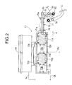
FIG. 2] FIG. 2 is an enlarged view of a portion indicated by anarrow 2 inFIG. 1 . (first embodiment) - [
FIG. 3] FIG. 3 is an enlarged sectional view of a slave cylinder. (first embodiment) - [
FIG. 4] FIG. 4 is a diagram of the fluid pressure circuit under an abnormal condition (before closing ports of a master cylinder). (first embodiment) - [
FIG. 5] FIG. 5 is a diagram of the fluid pressure circuit under an abnormal condition (after the ports of the master cylinder are closed). (first embodiment) - [
FIG. 6] FIG. 6 is time charts explaining operations. (first embodiment) -
- 11
- Master cylinder
- 12
- Brake pedal
- 16
- Wheel cylinder
- 17
- Wheel cylinder
- 20
- Wheel cylinder
- 21
- Wheel cylinder
- 23
- Slave cylinder
- 25
- Reaction force admission valve
- 26
- Stroke simulator
- 32
- Electric motor
- 64
- Pump
- 79
- First link (link mechanism)
- 81
- Second link (link mechanism)
- A mode for carrying out the present invention is explained below based on
FIGS. 1 to 6 . - As shown in
FIG. 1 , a tandemtype master cylinder 11 includes rear and frontfluid pressure chambers brake pedal 12. The rearfluid pressure chamber 13A is connected for example towheel cylinders disc brake devices fluid pressure chamber 13B is connected for example towheel cylinders disc brake devices - As shown in
FIG. 2 , themaster cylinder 11 includes arear piston 71A located rearward of the rearfluid pressure chamber 13A, afront piston 71B located rearward of the frontfluid pressure chamber 13B, and returnsprings fluid pressure chambers fluid pressure chamber 13A, arear inlet port 73A that communicates with areservoir 44 and arear outlet port 74A that communicates with the fluid path Pa are formed. In the frontfluid pressure chamber 13B, afront inlet port 73B that communicates with thereservoir 44 and afront outlet port 74B that communicates with the fluid path Qa are formed. - A
push rod 75 that is fitted in arecess 71a formed in a rear end of therear piston 71A is provided with aflange 75a at its rear portion, and acoil spring 76 is compressedly provided between a front face of theflange 75a and the rear end of therear piston 71A. One end of afirst link 79 is pivotably supported by apin 78 to an intermediate portion of thebrake pedal 12 pivotably supported at an upper end to a vehicle body by apin 77. The other end of thefirst link 79 is pivotably supported by apin 82 to an intermediate portion of asecond link 81 pivotably supported at one end to the vehicle body by apin 80, while the other end of thesecond link 81 is pivotably supported by apin 83 to a rear end of thepush rod 75. Thebrake pedal 12 is urged in a direction of retreating movement by areturn spring 84, and its limit of retreating movement is restricted by an unillustrated stopper. In this state, clearance α that effects ineffective stroke of thebrake pedal 12 is formed between a front end of thepush rod 75 and therecess 71a formed in the rear end of therear piston 71A. - Thus, when the driver applies pressure on the
brake pedal 12, the pedal pressure is transmitted to therear piston 71A through thefirst link 79, thesecond link 81 and thepush rod 75 thereby to generate brake fluid pressure in the rearfluid pressure chamber 13A. When the brake fluid pressure is generated in the rearfluid pressure chamber 13A, thefront piston 71B moves forward thereby to generate brake fluid pressure in the frontfluid pressure chamber 13B. At this time, the connection of thebrake pedal 12 to thepush rod 75 via the first andsecond links brake pedal 12 and transmitting the boosted pressure to thepush rod 75. Also, the clearance α formed between the front end of thepush rod 75 and therecess 71a of therear piston 71A enables eliminating the feeling that thebrake pedal 12 does not move smoothly due to static friction of parts at the start of application of pressure on thebrake pedal 12, and hence achieving an improvement in pedal feeling. - Returning to
FIG. 1 , a shut-offvalve 22A as a normally open type electromagnetic valve is disposed between the fluid paths Pa and Pb, a shut-offvalve 22B as a normally open type electromagnetic valve is disposed between the fluid paths Qa and Qb, aslave cylinder 23 is disposed between the fluid paths Pb, Qb and the fluid paths Pc, Qc, and a VSA (vehicle stability assist)device 24 is disposed between the fluid paths Pc, Qc and the fluid paths Pd, Pe and Qd, Qe. - A
stroke simulator 26 is connected to fluid paths Ra and Rb branching off from the fluid path Qa, via a reactionforce admission valve 25 as a normally closed type electromagnetic valve. Thestroke simulator 26 is configured such that apiston 29 which is urged by aspring 28 is slidably fitted in acylinder 27, and afluid pressure chamber 30 formed on thepiston 29 on the side thereof opposite to thespring 28 communicates with the fluid path Rb. - An
actuator 31 of theslave cylinder 23 includes anelectric motor 32, adrive bevel gear 33 provided on an output shaft of theelectric motor 32, a drivenbevel gear 34 that is in engagement with thedrive bevel gear 33, and aball screw mechanism 35 that operates by the drivenbevel gear 34. - A
rear piston 38A and afront piston 38B which are urged in the direction of retreating movements by the return springs 37A and 37B, respectively, are slidably disposed in a rear portion and a front portion of acylinder body 36 of theslave cylinder 23, and a rearfluid pressure chamber 39A and a frontfluid pressure chamber 39B are defined on the front faces of therear piston 38A and thefront piston 38B, respectively. - The rear
fluid pressure chamber 39A communicates with the fluid path Pb through arear input port 40A and also communicates with the fluid path Pc through arear output port 41A, while the frontfluid pressure chamber 39B communicates with the fluid path Qb through afront input port 40B and also communicates with the fluid path Qc through afront output port 41B. - Thus, in
FIG. 1 , when theelectric motor 32 is driven in a direction, the rear andfront pistons drive bevel gear 33, the drivenbevel gear 34 and theball screw mechanism 35, and, at the instant of blockage of the rear andfront input ports fluid pressure chambers front output ports - The structure of the
VSA device 24 is a well-known one, and the VSA devices having the same structure are provided in afirst brake actuator 51A that controls the first system of thedisc brake devices second brake actuator 51B that controls the second system of thedisc brake devices - Description will be given below by way of representative of the
first brake actuator 51A for the first system of thedisc brake devices - The
first brake actuator 51A is disposed between the fluid path Pc leading to therear output port 41A of theslave cylinder 23, located on the upstream side, and the fluid paths Pd and Pe leading to thewheel cylinders - The first brake actuator 51A includes common fluid paths 52 and 53 for the wheel cylinders 16 and 17 of the left front wheel and the right rear wheel, and includes a regulator valve 54 constructed of a normally open type electromagnetic valve with variable opening degree disposed between the fluid path Pc and the fluid path 52; a check valve 55 disposed in parallel with the regulator valve 54 to permit flow of brake fluid from the fluid path Pc side to the fluid path 52 side; an in-valve 56 constructed of a normally open type electromagnetic valve disposed between the fluid path 52 and the fluid path Pe; a check valve 57 disposed in parallel with the in-valve 56 to permit flow of brake fluid from the fluid path Pe side to the fluid path 52 side; an in-valve 58 constructed of a normally open type electromagnetic valve disposed between the fluid path 52 and the fluid path Pd; a check valve 59 disposed in parallel with the in-valve 58 to permit flow of brake fluid from the fluid path Pd side to the fluid path 52 side; an out-valve 60 constructed of a normally closed type electromagnetic valve disposed between the fluid path Pe and the fluid path 53; an out-valve 61 constructed of a normally closed type electromagnetic valve disposed between the fluid path Pd and the fluid path 53; a reservoir 62 connected to the fluid path 53; a check valve 63 disposed between the fluid path 53 and the fluid path 52 to permit flow of brake fluid from the fluid path 53 side to the fluid path 52 side; a pump 64 disposed between the check valve 63 and the fluid path 52 to feed brake fluid from the fluid path 53 side to the fluid path 52 side; an electric motor 65 that drives the pump 64; and a suction valve 66 constructed of a normally closed type electromagnetic valve disposed between an intermediate position between the check valve 63 and the pump 64 and the fluid path Pc.
- Incidentally, the
electric motor 65 is common for thepumps second brake actuators electric motors pumps - The
brake pedal 12 is provided with a stroke sensor Sa that detects the stroke of thebrake pedal 12, a fluid pressure sensor Sb that detects brake fluid pressure generated by theslave cylinder 23 is provided in the fluid path Pc on one inlet side of theVSA device 24, and wheel speed sensors Sc, ... are provided in four wheels, respectively. - As is apparent from
FIG. 3 , theslave cylinder 23 is such that the rearfluid pressure chamber 39A communicates with the fluid path Pb through therear input port 40A and arear supply port 42A and also communicates with the fluid path Pc through therear output port 41A. Also, the frontfluid pressure chamber 39B communicates with the fluid path Qb through thefront input port 40B and a firstfront supply port 42B and also communicates with the fluid path Qc through thefront output port 41B. - A front end of the
rear piston 38A is provided with a first rear cup seal C1 facing forward (so as to perform a sealing function during forward movement), while a rear end of therear piston 38A is provided with a second rear cup seal C2 facing forward. A front end of thefront piston 38B is provided with a first front cup seal C3 facing forward, while a rear end of thefront piston 38B is provided with a second front cup seal C4 facing backward (so as to perform a sealing function during backward movement). Further, an intermediate portion of thefront piston 38B is provided with a third front cup seal C5 facing forward. - A
rear reservoir chamber 38a sandwiched between the first and second rear cup seals C1 and C2 is formed in an intermediate portion of therear piston 38A, and therear supply port 42A communicates with therear reservoir chamber 38a. A firstfront reservoir chamber 38b sandwiched between the first and third front cup seals C3 and C5 is formed in a front portion of thefront piston 38B, and the firstfront supply port 42B communicates with the firstfront reservoir chamber 38b. Also, a secondfront reservoir chamber 38c sandwiched between the second and third front cup seals C4 and C5 is formed in a rear portion of thefront piston 38B, and a secondfront supply port 43 communicates with the secondfront reservoir chamber 38c. The secondfront supply port 43 communicates with thereservoir 44 of themaster cylinder 11 through a fluid path Rc. (SeeFIG. 1 .) - The rear
fluid pressure chamber 39A is kept fluid-tight by being sandwiched between the forward-facing first rear cup seal C1 and the backward-facing second front cup seal C4, and also, the forward-facing second rear cup seal C2 blocks the fluid from leaking rearward from therear reservoir chamber 38a. The frontfluid pressure chamber 39B is kept fluid-tight by the forward-facing first front cup seal C3, and also, the forward-facing third front cup seal C5 blocks the fluid from leaking rearward from the firstfront reservoir chamber 38b. - The brake fluid in the second
front reservoir chamber 38c that communicates with thereservoir 44 of themaster cylinder 11 through the secondfront supply port 43 and the fluid path Rc can flow into the rearfluid pressure chamber 39A through the second front cup seal C4 that functions as a one-way valve, and also can flow into the frontfluid pressure chamber 39B through the third front cup seal C5 and the first front cup seal C3 that function as one-way valves. - During non-operation of the
slave cylinder 23, the first rear cup seal C1 of therear piston 38A is located immediately rearward of therear input port 40A, and slight forward movement of therear piston 38A allows the first rear cup seal C1 to pass therear input port 40A, thereby generating brake fluid pressure in the rearfluid pressure chamber 39A. During non-operation of theslave cylinder 23, the first front cup seal C3 of thefront piston 38B is located immediately rearward of thefront input port 40B, and slight forward movement of thefront piston 38B allows the first front cup seal C3 to pass thefront input port 40B, thereby generating brake fluid pressure in the frontfluid pressure chamber 39B. - An unillustrated electronic control unit supplied with input signals from the stroke sensor Sa, the fluid pressure sensor Sb and the wheel speed sensors Sc, ..., controls operation of the shut-off
valves VSA device 24, the reactionforce admission valve 25 and theslave cylinder 23. - Next, operations or effects of the embodiment of the present invention including the above-described configuration will be described.
- Under normal conditions where the system functions normally, as shown in
FIG 1 , the shut-offvalves force admission valve 25 constructed of the normally closed type electromagnetic valve is opened by excitation. In this state, when the stroke sensor Sa detects that the driver applies pressure on thebrake pedal 12, theelectric motor 32 of theslave cylinder 23 operates to effect forward movement of the rear andfront pistons fluid pressure chambers wheel cylinders disc brake devices valves VSA device 24 thereby to apply brakes to the wheels, respectively. - Slight forward movement of the rear and
front pistons slave cylinder 23 interrupts communication between the fluid paths Pb, Qb and the rear and frontfluid pressure chambers master cylinder 11 is not transmitted to thedisc brake devices fluid pressure chamber 13B of themaster cylinder 11 is transmitted to thefluid pressure chamber 30 of thestroke simulator 26 through the opened reactionforce admission valve 25 to effect movement of thepiston 29 against thespring 28 and thereby permit the stroke of thebrake pedal 12 and also generate a pseudo pedal reaction force, thus enabling elimination of driver's uncomfortable feeling. - At this time, a target brake fluid pressure is mapped from the stroke of the
brake pedal 12 detected by the stroke sensor Sa, a target stroke of theslave cylinder 23 is further mapped from the target brake fluid pressure, and an angle of rotation of theelectric motor 32 of theslave cylinder 23 is controlled so as to achieve the target stroke, thereby enabling theslave cylinder 23 to generate brake fluid pressure according to the stroke of thebrake pedal 12 and supply the brake fluid pressure to thewheel cylinders - Next, operations or effects of the
VSA device 24 will be described. - Under non-operation of the
VSA device 24, theregulator valves suction valves valves valves slave cylinder 23 operates by the driver applying pressure on thebrake pedal 12 in order to perform braking, brake fluid pressure outputted through the rear andfront output ports slave cylinder 23 can be fed from theregulator valves valves wheel cylinders - Under operation of the
VSA device 24, with thesuction valves pumps electric motor 65, and brake fluid that has been sucked from theslave cylinder 23 side through thesuction valves pumps regulator valves valves regulator valves fluid paths wheel cylinders valves brake pedal 12. - Thus, the first and
second brake actuators - Also, during braking by the driver applying pressure on the
brake pedal 12, for example if the fact that the left front wheel treads on a road with a low coefficient of friction and exhibits a tendency to lock is detected based on outputs from the wheel speed sensors Sc, ... , one in-valve 58 of thefirst brake actuator 51A is closed by excitation and one out-valve 61 is opened by excitation thereby to let brake fluid pressure in thewheel cylinder 16 of the left front wheel escape into thereservoir 62 and reduce the brake fluid pressure to a predetermined pressure, and thereafter, the out-valve 61 is closed by demagnetization thereby to hold the brake fluid pressure in thewheel cylinder 16 of the left front wheel. When the locking tendency of thewheel cylinder 16 of the left front wheel is consequently being eliminated, the in-valve 58 is opened by demagnetization thereby to feed brake fluid pressure from therear output port 41A of theslave cylinder 23 to thewheel cylinder 16 of the left front wheel and increase the brake fluid pressure to a predetermined pressure, thereby increasing the braking force. - If the left front wheel exhibits the tendency to lock again due to the increase in the pressure, the above-described procedure that involves reducing the pressure, then holding the pressure, and then increasing the pressure can be repeated thereby to perform ABS (antilock braking system) control that minimizes a braking distance, while suppressing the locking of the left front wheel.
- Although description has been given above with regard to the ABS control as performed when the
wheel cylinder 16 of the left front wheel exhibits the tendency to lock, the ABS control may be performed in the same manner when thewheel cylinder 17 of the right rear wheel, thewheel cylinder 20 of the right front wheel, or thewheel cylinder 21 of the left rear wheel exhibits the tendency to lock. - Now, under abnormal conditions such as situations where the
slave cylinder 23 is incapable of operation due to its failure, as shown inFIG. 4 , the shut-offvalves force admission valve 25 is closed, the in-valves valves FIG. 1 , theregulator valves suction valves pumps brake pedal 12, brake fluid that has been sucked from theslave cylinder 23 side through thesuction valves pumps regulator valves valves regulator valves fluid paths wheel cylinders valves wheel cylinders - The above-described driving of the
pumps front pistons master cylinder 11 pass the rear andfront inlet ports fluid pressure chambers brake pedal 12 by the driver and the generation of the brake fluid pressure by themaster cylinder 11, a predetermined amount of brake fluid can be supplied in advance to thewheel cylinders - When the driver further applies pressure on the
brake pedal 12 and thereby the rear andfront pistons master cylinder 11 pass the rear andfront inlet ports fluid pressure chambers FIG. 5 , theregulator valves suction valves fluid pressure chambers master cylinder 11 passes the shut-offvalves fluid pressure chambers slave cylinder 23 and the in-valves stroke simulator 26, that is, without increasing the stroke of thebrake pedal 12, and effects operation of thewheel cylinders disc brake devices -
FIG. 6 is a graph explaining the above-described operations or effects. While as shown inFIG. 6(A) the stroke of thebrake pedal 12 gradually increases and reaches port closing stroke in which the rear andfront inlet ports master cylinder 11 are blocked, theregulator valves FIG. 4 ) concurrently with operation of thepumps wheel cylinders FIGS. 6(B), (C) and (D) . As a result, when the brake fluid pressure is generated by blocking the rear andfront outlet ports master cylinder 11 by increasing the stroke of thebrake pedal 12, the brake fluid supplied by themaster cylinder 11 is added to the prefilled brake fluid to thus increase the brake fluid pressure in thewheel cylinders FIG. 6(B) .) - Thus, the start of the operation of the brake fluid pressure supplied to the
wheel cylinders brake pedal 12 for achieving a required brake fluid pressure. The broken line ofFIG. 6(B) shows characteristics as observed when the above-described prefilling does not take place, and the start of the operation of the brake fluid pressure supplied to thewheel cylinders brake pedal 12 for achieving the required brake fluid pressure. - According to the embodiment, as described above, the prefilling for the
wheel cylinders brake pedal 12 for achieving the required brake fluid pressure. Also, even when, in order to improve the pedal feeling, the clearance α (seeFIG. 2 ) is provided between thepush rod 75 of themaster cylinder 11 and therear piston 71A thereby to set the ineffective stroke, an increase in the stroke of thebrake pedal 12 due to the ineffective stroke can be compensated for and reduced to a normal stroke. - Moreover, the time at which the
pumps wheel cylinders brake pedal 12, and thus, the prefilling takes place under a condition where the brake fluid pressure on thewheel cylinders pumps brake pedal 12 in which the brake fluid pressure is high. - An embodiment of the present invention is explained above, but the present invention may be modified in a variety of ways as long as the modifications do not depart from the gist thereof.
- For example, in the embodiment the prefilling for the
wheel cylinders pump 64 of theVSA device 24, but it is also possible to use the pump of an ABS device instead of theVSA device 24.
Claims (4)
- A braking device including:a master cylinder (11) that generates brake fluid pressure by operation of a brake pedal (12) by a driver;a wheel cylinder (16,17, 20, 21) that performs braking on a wheel; anda slave cylinder (23) disposed between the master cylinder (11) and the wheel cylinder (16, 17, 20, 21), the slave cylinder (23) generating brake fluid pressure by an electric motor (32) that operates according to the operation of the brake pedal (12),the wheel cylinder (16, 17, 20, 21) being configured to be brought into operation by the brake fluid pressure generated by the master cylinder (11) under a fault condition of the slave cylinder (23),characterized in thata pump (64) that feeds brake fluid is disposed between the slave cylinder (23) and the wheel cylinder (16, 17, 20, 21), and, under the fault condition of the slave cylinder (23), during an initial period of the operation of the brake pedal (12), the pump (64) feeds the brake fluid to the wheel cylinder (16, 17, 20, 21).
- The braking device according to claim 1, wherein the brake pedal (12) includes a link mechanism (79, 81) that boosts pedal pressure applied by the driver and transmits the boosted pressure to the master cylinder (11).
- The braking device according to claim 1 or 2, wherein ineffective stroke is set for the brake pedal (12) before the master cylinder (11) starts operating.
- The braking device according to any one of claims 1 to 3, further including a stroke simulator (26) connected to the master cylinder (11) via a reaction force admission valve (25), wherein the reaction force admission valve (25) is closed before the pump (64) is driven.
Applications Claiming Priority (2)
| Application Number | Priority Date | Filing Date | Title |
|---|---|---|---|
| JP2009067929 | 2009-03-19 | ||
| PCT/JP2010/054567 WO2010107067A1 (en) | 2009-03-19 | 2010-03-17 | Brake device |
Publications (3)
| Publication Number | Publication Date |
|---|---|
| EP2409885A1 true EP2409885A1 (en) | 2012-01-25 |
| EP2409885A4 EP2409885A4 (en) | 2012-09-05 |
| EP2409885B1 EP2409885B1 (en) | 2013-07-17 |
Family
ID=42739726
Family Applications (1)
| Application Number | Title | Priority Date | Filing Date |
|---|---|---|---|
| EP10753558.5A Not-in-force EP2409885B1 (en) | 2009-03-19 | 2010-03-17 | Operating method for a braking device |
Country Status (5)
| Country | Link |
|---|---|
| US (1) | US8919893B2 (en) |
| EP (1) | EP2409885B1 (en) |
| JP (1) | JP5497739B2 (en) |
| CN (1) | CN102307760B (en) |
| WO (1) | WO2010107067A1 (en) |
Cited By (8)
| Publication number | Priority date | Publication date | Assignee | Title |
|---|---|---|---|---|
| CN103950444A (en) * | 2014-04-14 | 2014-07-30 | 同济大学 | Electronic hydraulic brake system capable of reducing liquid outlets of main cylinder |
| CN104071142A (en) * | 2014-07-08 | 2014-10-01 | 清华大学 | Driven-by-wire brake system for electric automobile |
| DE102014211380A1 (en) * | 2014-06-13 | 2015-12-17 | Ford Global Technologies, Llc | Method for operating an electromechanical vehicle brake system |
| EP2995516A4 (en) * | 2013-05-08 | 2016-04-20 | Toyota Motor Co Ltd | Vehicle brake device |
| US9539992B2 (en) | 2014-06-13 | 2017-01-10 | Ford Global Technologies, Llc | Method for operating an electromechanical vehicle brake system |
| US9592812B2 (en) | 2014-06-13 | 2017-03-14 | Ford Global Technologies, Llc | Method for operating an electromechanical vehicle brake system |
| WO2019215030A1 (en) * | 2018-05-09 | 2019-11-14 | Ipgate Ag | Brake system |
| US11472388B2 (en) | 2017-06-20 | 2022-10-18 | Ipgate Ag | Brake system |
Families Citing this family (13)
| Publication number | Priority date | Publication date | Assignee | Title |
|---|---|---|---|---|
| US8579386B2 (en) * | 2009-06-12 | 2013-11-12 | Honda Motor Co., Ltd. | Vehicle brake device |
| JP5314801B2 (en) * | 2010-10-04 | 2013-10-16 | 本田技研工業株式会社 | Slave cylinder |
| JP5352602B2 (en) * | 2011-01-31 | 2013-11-27 | 本田技研工業株式会社 | Brake device for vehicle |
| DE102012202645A1 (en) * | 2011-04-28 | 2012-10-31 | Continental Teves Ag & Co. Ohg | Brake system for motor vehicles |
| KR101338431B1 (en) * | 2011-07-08 | 2013-12-10 | 현대자동차주식회사 | Regenerative braking system for vehicle |
| JP5626168B2 (en) * | 2011-09-27 | 2014-11-19 | 株式会社アドヴィックス | Brake control device for vehicle |
| JP5841455B2 (en) * | 2012-02-24 | 2016-01-13 | 日立オートモティブシステムズ株式会社 | Brake device |
| JP5631937B2 (en) * | 2012-07-17 | 2014-11-26 | 本田技研工業株式会社 | Braking force generator |
| KR102079248B1 (en) * | 2013-09-12 | 2020-02-19 | 현대모비스 주식회사 | Electronic hydraulic brake device |
| KR101536247B1 (en) * | 2014-04-25 | 2015-07-13 | 현대모비스 주식회사 | Brake device and brake method for vehicle |
| US10913436B2 (en) * | 2018-03-30 | 2021-02-09 | Veoneer Nissin Brake Systems Japan Co., Ltd. | Systems and methods for reducing energy consumption within a braking system of a vehicle |
| DE102018222488A1 (en) * | 2018-12-20 | 2020-06-25 | Robert Bosch Gmbh | Electro-hydraulic power brake system for an autonomous land vehicle |
| JP7444010B2 (en) | 2020-09-29 | 2024-03-06 | 株式会社アドヴィックス | Vehicle braking device |
Citations (3)
| Publication number | Priority date | Publication date | Assignee | Title |
|---|---|---|---|---|
| DE3424912A1 (en) * | 1984-07-06 | 1986-01-16 | Alfred Teves Gmbh, 6000 Frankfurt | Electronically controlled brake-actuating system |
| EP1138565A2 (en) * | 2000-03-30 | 2001-10-04 | Sumitomo (Sei) Brake Systems, Inc. | Method of controlling hydraulic brake system for vehicle |
| EP1334893A2 (en) * | 2002-02-11 | 2003-08-13 | Robert Bosch Gmbh | Electro-hydraulic vehicle braking system |
Family Cites Families (13)
| Publication number | Priority date | Publication date | Assignee | Title |
|---|---|---|---|---|
| US3911760A (en) * | 1974-10-02 | 1975-10-14 | Gen Motors Corp | Variable ratio brake pedal linkage |
| DE3428869A1 (en) * | 1984-08-04 | 1986-02-13 | Alfred Teves Gmbh, 6000 Frankfurt | BRAKE-SLIP-CONTROLLED BRAKE SYSTEM |
| DE3607366A1 (en) * | 1986-03-06 | 1987-09-10 | Teves Gmbh Alfred | HYDRAULIC BRAKE SYSTEM FOR MOTOR VEHICLES |
| JP3900826B2 (en) * | 2000-12-06 | 2007-04-04 | トヨタ自動車株式会社 | Automatic engine stop / start device |
| JP2005343366A (en) | 2004-06-04 | 2005-12-15 | Honda Motor Co Ltd | Braking device |
| DE102005017958A1 (en) | 2004-10-15 | 2006-04-27 | Continental Teves Ag & Co. Ohg | Brake system for motor vehicles |
| CN100577484C (en) * | 2004-10-15 | 2010-01-06 | 大陆-特韦斯贸易合伙股份公司及两合公司 | Brake device for motor vehicles |
| JP4508117B2 (en) * | 2006-01-16 | 2010-07-21 | トヨタ自動車株式会社 | Brake system |
| JP4661621B2 (en) | 2006-02-15 | 2011-03-30 | 株式会社アドヴィックス | Brake control device for vehicle |
| JP2007276683A (en) * | 2006-04-10 | 2007-10-25 | Advics:Kk | Vehicular brake control device |
| JP5048348B2 (en) * | 2007-01-22 | 2012-10-17 | 本田技研工業株式会社 | Brake device |
| JP4792416B2 (en) * | 2007-03-12 | 2011-10-12 | 本田技研工業株式会社 | Brake device |
| JP2008273440A (en) | 2007-05-01 | 2008-11-13 | Hitachi Ltd | Brake fluid pressure control device |
-
2010
- 2010-03-17 CN CN201080006524.1A patent/CN102307760B/en active Active
- 2010-03-17 WO PCT/JP2010/054567 patent/WO2010107067A1/en active Application Filing
- 2010-03-17 EP EP10753558.5A patent/EP2409885B1/en not_active Not-in-force
- 2010-03-17 US US13/256,792 patent/US8919893B2/en not_active Expired - Fee Related
- 2010-03-17 JP JP2011504868A patent/JP5497739B2/en not_active Expired - Fee Related
Patent Citations (3)
| Publication number | Priority date | Publication date | Assignee | Title |
|---|---|---|---|---|
| DE3424912A1 (en) * | 1984-07-06 | 1986-01-16 | Alfred Teves Gmbh, 6000 Frankfurt | Electronically controlled brake-actuating system |
| EP1138565A2 (en) * | 2000-03-30 | 2001-10-04 | Sumitomo (Sei) Brake Systems, Inc. | Method of controlling hydraulic brake system for vehicle |
| EP1334893A2 (en) * | 2002-02-11 | 2003-08-13 | Robert Bosch Gmbh | Electro-hydraulic vehicle braking system |
Non-Patent Citations (1)
| Title |
|---|
| See also references of WO2010107067A1 * |
Cited By (12)
| Publication number | Priority date | Publication date | Assignee | Title |
|---|---|---|---|---|
| EP2995516A4 (en) * | 2013-05-08 | 2016-04-20 | Toyota Motor Co Ltd | Vehicle brake device |
| CN103950444A (en) * | 2014-04-14 | 2014-07-30 | 同济大学 | Electronic hydraulic brake system capable of reducing liquid outlets of main cylinder |
| CN103950444B (en) * | 2014-04-14 | 2017-07-07 | 同济大学 | A kind of EHB for reducing master cylinder liquid outlet |
| DE102014211380A1 (en) * | 2014-06-13 | 2015-12-17 | Ford Global Technologies, Llc | Method for operating an electromechanical vehicle brake system |
| US9539994B2 (en) | 2014-06-13 | 2017-01-10 | Ford Global Technologies, Llc | Method for operating an electromechanical vehicle braking |
| US9539992B2 (en) | 2014-06-13 | 2017-01-10 | Ford Global Technologies, Llc | Method for operating an electromechanical vehicle brake system |
| US9592812B2 (en) | 2014-06-13 | 2017-03-14 | Ford Global Technologies, Llc | Method for operating an electromechanical vehicle brake system |
| DE102014211380B4 (en) | 2014-06-13 | 2021-08-05 | Ford Global Technologies, Llc | Method for operating an electromechanical vehicle braking system |
| CN104071142A (en) * | 2014-07-08 | 2014-10-01 | 清华大学 | Driven-by-wire brake system for electric automobile |
| CN104071142B (en) * | 2014-07-08 | 2016-06-15 | 清华大学 | A kind of electric motor car line control brake system |
| US11472388B2 (en) | 2017-06-20 | 2022-10-18 | Ipgate Ag | Brake system |
| WO2019215030A1 (en) * | 2018-05-09 | 2019-11-14 | Ipgate Ag | Brake system |
Also Published As
| Publication number | Publication date |
|---|---|
| CN102307760B (en) | 2015-01-28 |
| EP2409885A4 (en) | 2012-09-05 |
| JPWO2010107067A1 (en) | 2012-09-20 |
| JP5497739B2 (en) | 2014-05-21 |
| US8919893B2 (en) | 2014-12-30 |
| WO2010107067A1 (en) | 2010-09-23 |
| CN102307760A (en) | 2012-01-04 |
| EP2409885B1 (en) | 2013-07-17 |
| US20120000738A1 (en) | 2012-01-05 |
Similar Documents
| Publication | Publication Date | Title |
|---|---|---|
| EP2409885B1 (en) | Operating method for a braking device | |
| US8328297B2 (en) | Brake system | |
| EP1970271B1 (en) | Brake system | |
| US8550573B2 (en) | Method of eliminating seizure of slave cylinder of brake device | |
| JP5220827B2 (en) | Brake device for vehicle | |
| JP5513603B2 (en) | Brake device for vehicle and control method for vehicle brake device | |
| JP4999416B2 (en) | Brake device | |
| JP4832460B2 (en) | Brake device | |
| US8496301B2 (en) | Vehicle brake mechanism and method for controlling the vehicle brake mechanism | |
| KR101901043B1 (en) | Brake control device, braking system, and brake hydraulic pressure generation method | |
| US8801110B2 (en) | Vehicle brake device | |
| JP2008143419A (en) | Braking device | |
| JP2008174005A (en) | Brake device | |
| JP2009190425A (en) | Brake device and automatic brake actuator | |
| JP2010095023A (en) | Vehicular brake device | |
| JP5204011B2 (en) | Bleeding method for brake device | |
| JP5005555B2 (en) | Brake device | |
| JP2008100631A (en) | Brake system | |
| JP5124037B2 (en) | Brake device | |
| JP2012176745A (en) | Brake device for vehicle | |
| JP7318458B2 (en) | vehicle braking device | |
| JP2010047044A (en) | Vehicular brake device | |
| WO2024070484A1 (en) | Braking device | |
| JP4970293B2 (en) | Brake device | |
| JP6029281B2 (en) | Brake device for vehicle |
Legal Events
| Date | Code | Title | Description |
|---|---|---|---|
| PUAI | Public reference made under article 153(3) epc to a published international application that has entered the european phase |
Free format text: ORIGINAL CODE: 0009012 |
|
| 17P | Request for examination filed |
Effective date: 20110822 |
|
| AK | Designated contracting states |
Kind code of ref document: A1 Designated state(s): AT BE BG CH CY CZ DE DK EE ES FI FR GB GR HR HU IE IS IT LI LT LU LV MC MK MT NL NO PL PT RO SE SI SK SM TR |
|
| DAX | Request for extension of the european patent (deleted) | ||
| A4 | Supplementary search report drawn up and despatched |
Effective date: 20120808 |
|
| RIC1 | Information provided on ipc code assigned before grant |
Ipc: B60T 8/17 20060101ALI20120802BHEP Ipc: B60T 7/06 20060101ALI20120802BHEP Ipc: B60T 8/00 20060101AFI20120802BHEP Ipc: B60T 17/18 20060101ALI20120802BHEP |
|
| 17Q | First examination report despatched |
Effective date: 20120829 |
|
| GRAP | Despatch of communication of intention to grant a patent |
Free format text: ORIGINAL CODE: EPIDOSNIGR1 |
|
| RIN1 | Information on inventor provided before grant (corrected) |
Inventor name: HATANO KUNIMICHI C/O HONDA R&D CO., LTD. Inventor name: INOUE ARATA C/O HONDA R&D CO., LTD. |
|
| GRAS | Grant fee paid |
Free format text: ORIGINAL CODE: EPIDOSNIGR3 |
|
| GRAA | (expected) grant |
Free format text: ORIGINAL CODE: 0009210 |
|
| AK | Designated contracting states |
Kind code of ref document: B1 Designated state(s): AT BE BG CH CY CZ DE DK EE ES FI FR GB GR HR HU IE IS IT LI LT LU LV MC MK MT NL NO PL PT RO SE SI SK SM TR |
|
| REG | Reference to a national code |
Ref country code: GB Ref legal event code: FG4D |
|
| REG | Reference to a national code |
Ref country code: CH Ref legal event code: EP |
|
| REG | Reference to a national code |
Ref country code: IE Ref legal event code: FG4D |
|
| REG | Reference to a national code |
Ref country code: AT Ref legal event code: REF Ref document number: 621989 Country of ref document: AT Kind code of ref document: T Effective date: 20130815 |
|
| REG | Reference to a national code |
Ref country code: DE Ref legal event code: R096 Ref document number: 602010008690 Country of ref document: DE Effective date: 20130912 |
|
| REG | Reference to a national code |
Ref country code: AT Ref legal event code: MK05 Ref document number: 621989 Country of ref document: AT Kind code of ref document: T Effective date: 20130717 |
|
| REG | Reference to a national code |
Ref country code: NL Ref legal event code: VDEP Effective date: 20130717 |
|
| REG | Reference to a national code |
Ref country code: LT Ref legal event code: MG4D |
|
| PG25 | Lapsed in a contracting state [announced via postgrant information from national office to epo] |
Ref country code: AT Free format text: LAPSE BECAUSE OF FAILURE TO SUBMIT A TRANSLATION OF THE DESCRIPTION OR TO PAY THE FEE WITHIN THE PRESCRIBED TIME-LIMIT Effective date: 20130717 Ref country code: IS Free format text: LAPSE BECAUSE OF FAILURE TO SUBMIT A TRANSLATION OF THE DESCRIPTION OR TO PAY THE FEE WITHIN THE PRESCRIBED TIME-LIMIT Effective date: 20131117 Ref country code: NO Free format text: LAPSE BECAUSE OF FAILURE TO SUBMIT A TRANSLATION OF THE DESCRIPTION OR TO PAY THE FEE WITHIN THE PRESCRIBED TIME-LIMIT Effective date: 20131017 Ref country code: HR Free format text: LAPSE BECAUSE OF FAILURE TO SUBMIT A TRANSLATION OF THE DESCRIPTION OR TO PAY THE FEE WITHIN THE PRESCRIBED TIME-LIMIT Effective date: 20130717 Ref country code: CY Free format text: LAPSE BECAUSE OF FAILURE TO SUBMIT A TRANSLATION OF THE DESCRIPTION OR TO PAY THE FEE WITHIN THE PRESCRIBED TIME-LIMIT Effective date: 20130807 Ref country code: LT Free format text: LAPSE BECAUSE OF FAILURE TO SUBMIT A TRANSLATION OF THE DESCRIPTION OR TO PAY THE FEE WITHIN THE PRESCRIBED TIME-LIMIT Effective date: 20130717 Ref country code: BE Free format text: LAPSE BECAUSE OF FAILURE TO SUBMIT A TRANSLATION OF THE DESCRIPTION OR TO PAY THE FEE WITHIN THE PRESCRIBED TIME-LIMIT Effective date: 20130717 Ref country code: SE Free format text: LAPSE BECAUSE OF FAILURE TO SUBMIT A TRANSLATION OF THE DESCRIPTION OR TO PAY THE FEE WITHIN THE PRESCRIBED TIME-LIMIT Effective date: 20130717 Ref country code: PT Free format text: LAPSE BECAUSE OF FAILURE TO SUBMIT A TRANSLATION OF THE DESCRIPTION OR TO PAY THE FEE WITHIN THE PRESCRIBED TIME-LIMIT Effective date: 20131118 |
|
| PG25 | Lapsed in a contracting state [announced via postgrant information from national office to epo] |
Ref country code: NL Free format text: LAPSE BECAUSE OF FAILURE TO SUBMIT A TRANSLATION OF THE DESCRIPTION OR TO PAY THE FEE WITHIN THE PRESCRIBED TIME-LIMIT Effective date: 20130717 Ref country code: PL Free format text: LAPSE BECAUSE OF FAILURE TO SUBMIT A TRANSLATION OF THE DESCRIPTION OR TO PAY THE FEE WITHIN THE PRESCRIBED TIME-LIMIT Effective date: 20130717 Ref country code: LV Free format text: LAPSE BECAUSE OF FAILURE TO SUBMIT A TRANSLATION OF THE DESCRIPTION OR TO PAY THE FEE WITHIN THE PRESCRIBED TIME-LIMIT Effective date: 20130717 Ref country code: GR Free format text: LAPSE BECAUSE OF FAILURE TO SUBMIT A TRANSLATION OF THE DESCRIPTION OR TO PAY THE FEE WITHIN THE PRESCRIBED TIME-LIMIT Effective date: 20131018 Ref country code: ES Free format text: LAPSE BECAUSE OF FAILURE TO SUBMIT A TRANSLATION OF THE DESCRIPTION OR TO PAY THE FEE WITHIN THE PRESCRIBED TIME-LIMIT Effective date: 20131028 Ref country code: FI Free format text: LAPSE BECAUSE OF FAILURE TO SUBMIT A TRANSLATION OF THE DESCRIPTION OR TO PAY THE FEE WITHIN THE PRESCRIBED TIME-LIMIT Effective date: 20130717 Ref country code: SI Free format text: LAPSE BECAUSE OF FAILURE TO SUBMIT A TRANSLATION OF THE DESCRIPTION OR TO PAY THE FEE WITHIN THE PRESCRIBED TIME-LIMIT Effective date: 20130717 |
|
| PG25 | Lapsed in a contracting state [announced via postgrant information from national office to epo] |
Ref country code: CY Free format text: LAPSE BECAUSE OF FAILURE TO SUBMIT A TRANSLATION OF THE DESCRIPTION OR TO PAY THE FEE WITHIN THE PRESCRIBED TIME-LIMIT Effective date: 20130717 |
|
| PG25 | Lapsed in a contracting state [announced via postgrant information from national office to epo] |
Ref country code: SK Free format text: LAPSE BECAUSE OF FAILURE TO SUBMIT A TRANSLATION OF THE DESCRIPTION OR TO PAY THE FEE WITHIN THE PRESCRIBED TIME-LIMIT Effective date: 20130717 Ref country code: EE Free format text: LAPSE BECAUSE OF FAILURE TO SUBMIT A TRANSLATION OF THE DESCRIPTION OR TO PAY THE FEE WITHIN THE PRESCRIBED TIME-LIMIT Effective date: 20130717 Ref country code: DK Free format text: LAPSE BECAUSE OF FAILURE TO SUBMIT A TRANSLATION OF THE DESCRIPTION OR TO PAY THE FEE WITHIN THE PRESCRIBED TIME-LIMIT Effective date: 20130717 Ref country code: CZ Free format text: LAPSE BECAUSE OF FAILURE TO SUBMIT A TRANSLATION OF THE DESCRIPTION OR TO PAY THE FEE WITHIN THE PRESCRIBED TIME-LIMIT Effective date: 20130717 Ref country code: RO Free format text: LAPSE BECAUSE OF FAILURE TO SUBMIT A TRANSLATION OF THE DESCRIPTION OR TO PAY THE FEE WITHIN THE PRESCRIBED TIME-LIMIT Effective date: 20130717 |
|
| PLBE | No opposition filed within time limit |
Free format text: ORIGINAL CODE: 0009261 |
|
| STAA | Information on the status of an ep patent application or granted ep patent |
Free format text: STATUS: NO OPPOSITION FILED WITHIN TIME LIMIT |
|
| PG25 | Lapsed in a contracting state [announced via postgrant information from national office to epo] |
Ref country code: IT Free format text: LAPSE BECAUSE OF FAILURE TO SUBMIT A TRANSLATION OF THE DESCRIPTION OR TO PAY THE FEE WITHIN THE PRESCRIBED TIME-LIMIT Effective date: 20130717 |
|
| 26N | No opposition filed |
Effective date: 20140422 |
|
| REG | Reference to a national code |
Ref country code: DE Ref legal event code: R097 Ref document number: 602010008690 Country of ref document: DE Effective date: 20140422 |
|
| PGFP | Annual fee paid to national office [announced via postgrant information from national office to epo] |
Ref country code: GB Payment date: 20140319 Year of fee payment: 5 |
|
| PG25 | Lapsed in a contracting state [announced via postgrant information from national office to epo] |
Ref country code: LU Free format text: LAPSE BECAUSE OF FAILURE TO SUBMIT A TRANSLATION OF THE DESCRIPTION OR TO PAY THE FEE WITHIN THE PRESCRIBED TIME-LIMIT Effective date: 20140317 |
|
| REG | Reference to a national code |
Ref country code: CH Ref legal event code: PL |
|
| REG | Reference to a national code |
Ref country code: FR Ref legal event code: ST Effective date: 20141128 |
|
| REG | Reference to a national code |
Ref country code: IE Ref legal event code: MM4A |
|
| PG25 | Lapsed in a contracting state [announced via postgrant information from national office to epo] |
Ref country code: FR Free format text: LAPSE BECAUSE OF NON-PAYMENT OF DUE FEES Effective date: 20140331 Ref country code: LI Free format text: LAPSE BECAUSE OF NON-PAYMENT OF DUE FEES Effective date: 20140331 Ref country code: IE Free format text: LAPSE BECAUSE OF NON-PAYMENT OF DUE FEES Effective date: 20140317 Ref country code: CH Free format text: LAPSE BECAUSE OF NON-PAYMENT OF DUE FEES Effective date: 20140331 |
|
| GBPC | Gb: european patent ceased through non-payment of renewal fee |
Effective date: 20150317 |
|
| PG25 | Lapsed in a contracting state [announced via postgrant information from national office to epo] |
Ref country code: GB Free format text: LAPSE BECAUSE OF NON-PAYMENT OF DUE FEES Effective date: 20150317 |
|
| PG25 | Lapsed in a contracting state [announced via postgrant information from national office to epo] |
Ref country code: MT Free format text: LAPSE BECAUSE OF FAILURE TO SUBMIT A TRANSLATION OF THE DESCRIPTION OR TO PAY THE FEE WITHIN THE PRESCRIBED TIME-LIMIT Effective date: 20130717 |
|
| PG25 | Lapsed in a contracting state [announced via postgrant information from national office to epo] |
Ref country code: SM Free format text: LAPSE BECAUSE OF FAILURE TO SUBMIT A TRANSLATION OF THE DESCRIPTION OR TO PAY THE FEE WITHIN THE PRESCRIBED TIME-LIMIT Effective date: 20130717 |
|
| PG25 | Lapsed in a contracting state [announced via postgrant information from national office to epo] |
Ref country code: MC Free format text: LAPSE BECAUSE OF FAILURE TO SUBMIT A TRANSLATION OF THE DESCRIPTION OR TO PAY THE FEE WITHIN THE PRESCRIBED TIME-LIMIT Effective date: 20130717 |
|
| PG25 | Lapsed in a contracting state [announced via postgrant information from national office to epo] |
Ref country code: BG Free format text: LAPSE BECAUSE OF FAILURE TO SUBMIT A TRANSLATION OF THE DESCRIPTION OR TO PAY THE FEE WITHIN THE PRESCRIBED TIME-LIMIT Effective date: 20130717 |
|
| PG25 | Lapsed in a contracting state [announced via postgrant information from national office to epo] |
Ref country code: HU Free format text: LAPSE BECAUSE OF FAILURE TO SUBMIT A TRANSLATION OF THE DESCRIPTION OR TO PAY THE FEE WITHIN THE PRESCRIBED TIME-LIMIT; INVALID AB INITIO Effective date: 20100317 Ref country code: TR Free format text: LAPSE BECAUSE OF FAILURE TO SUBMIT A TRANSLATION OF THE DESCRIPTION OR TO PAY THE FEE WITHIN THE PRESCRIBED TIME-LIMIT Effective date: 20130717 |
|
| PG25 | Lapsed in a contracting state [announced via postgrant information from national office to epo] |
Ref country code: MK Free format text: LAPSE BECAUSE OF FAILURE TO SUBMIT A TRANSLATION OF THE DESCRIPTION OR TO PAY THE FEE WITHIN THE PRESCRIBED TIME-LIMIT Effective date: 20130717 |
|
| REG | Reference to a national code |
Ref country code: DE Ref legal event code: R084 Ref document number: 602010008690 Country of ref document: DE |
|
| PGFP | Annual fee paid to national office [announced via postgrant information from national office to epo] |
Ref country code: DE Payment date: 20190305 Year of fee payment: 10 |
|
| REG | Reference to a national code |
Ref country code: DE Ref legal event code: R119 Ref document number: 602010008690 Country of ref document: DE |
|
| PG25 | Lapsed in a contracting state [announced via postgrant information from national office to epo] |
Ref country code: DE Free format text: LAPSE BECAUSE OF NON-PAYMENT OF DUE FEES Effective date: 20201001 |