EP2409864A1 - Automotive air-conditioning system - Google Patents
Automotive air-conditioning system Download PDFInfo
- Publication number
- EP2409864A1 EP2409864A1 EP10425244A EP10425244A EP2409864A1 EP 2409864 A1 EP2409864 A1 EP 2409864A1 EP 10425244 A EP10425244 A EP 10425244A EP 10425244 A EP10425244 A EP 10425244A EP 2409864 A1 EP2409864 A1 EP 2409864A1
- Authority
- EP
- European Patent Office
- Prior art keywords
- heat exchanger
- branch
- configuration
- hot
- cold
- Prior art date
- Legal status (The legal status is an assumption and is not a legal conclusion. Google has not performed a legal analysis and makes no representation as to the accuracy of the status listed.)
- Granted
Links
Images

Classifications
-
- B—PERFORMING OPERATIONS; TRANSPORTING
- B60—VEHICLES IN GENERAL
- B60H—ARRANGEMENTS OF HEATING, COOLING, VENTILATING OR OTHER AIR-TREATING DEVICES SPECIALLY ADAPTED FOR PASSENGER OR GOODS SPACES OF VEHICLES
- B60H1/00—Heating, cooling or ventilating devices
- B60H1/00642—Control systems or circuits; Control members or indication devices for heating, cooling or ventilating devices
- B60H1/00814—Control systems or circuits characterised by their output, for controlling particular components of the heating, cooling or ventilating installation
- B60H1/00878—Control systems or circuits characterised by their output, for controlling particular components of the heating, cooling or ventilating installation the components being temperature regulating devices
- B60H1/00899—Controlling the flow of liquid in a heat pump system
- B60H1/00907—Controlling the flow of liquid in a heat pump system where the flow direction of the refrigerant changes and an evaporator becomes condenser
-
- B—PERFORMING OPERATIONS; TRANSPORTING
- B60—VEHICLES IN GENERAL
- B60H—ARRANGEMENTS OF HEATING, COOLING, VENTILATING OR OTHER AIR-TREATING DEVICES SPECIALLY ADAPTED FOR PASSENGER OR GOODS SPACES OF VEHICLES
- B60H1/00—Heating, cooling or ventilating devices
- B60H1/00357—Air-conditioning arrangements specially adapted for particular vehicles
- B60H1/00385—Air-conditioning arrangements specially adapted for particular vehicles for vehicles having an electrical drive, e.g. hybrid or fuel cell
-
- B—PERFORMING OPERATIONS; TRANSPORTING
- B60—VEHICLES IN GENERAL
- B60H—ARRANGEMENTS OF HEATING, COOLING, VENTILATING OR OTHER AIR-TREATING DEVICES SPECIALLY ADAPTED FOR PASSENGER OR GOODS SPACES OF VEHICLES
- B60H1/00—Heating, cooling or ventilating devices
- B60H1/00642—Control systems or circuits; Control members or indication devices for heating, cooling or ventilating devices
- B60H1/00814—Control systems or circuits characterised by their output, for controlling particular components of the heating, cooling or ventilating installation
- B60H1/00878—Control systems or circuits characterised by their output, for controlling particular components of the heating, cooling or ventilating installation the components being temperature regulating devices
- B60H1/00899—Controlling the flow of liquid in a heat pump system
-
- B—PERFORMING OPERATIONS; TRANSPORTING
- B60—VEHICLES IN GENERAL
- B60H—ARRANGEMENTS OF HEATING, COOLING, VENTILATING OR OTHER AIR-TREATING DEVICES SPECIALLY ADAPTED FOR PASSENGER OR GOODS SPACES OF VEHICLES
- B60H1/00—Heating, cooling or ventilating devices
- B60H1/32—Cooling devices
- B60H1/3204—Cooling devices using compression
- B60H1/3228—Cooling devices using compression characterised by refrigerant circuit configurations
- B60H1/32284—Cooling devices using compression characterised by refrigerant circuit configurations comprising two or more secondary circuits, e.g. at evaporator and condenser side
-
- B—PERFORMING OPERATIONS; TRANSPORTING
- B60—VEHICLES IN GENERAL
- B60L—PROPULSION OF ELECTRICALLY-PROPELLED VEHICLES; SUPPLYING ELECTRIC POWER FOR AUXILIARY EQUIPMENT OF ELECTRICALLY-PROPELLED VEHICLES; ELECTRODYNAMIC BRAKE SYSTEMS FOR VEHICLES IN GENERAL; MAGNETIC SUSPENSION OR LEVITATION FOR VEHICLES; MONITORING OPERATING VARIABLES OF ELECTRICALLY-PROPELLED VEHICLES; ELECTRIC SAFETY DEVICES FOR ELECTRICALLY-PROPELLED VEHICLES
- B60L1/00—Supplying electric power to auxiliary equipment of vehicles
- B60L1/003—Supplying electric power to auxiliary equipment of vehicles to auxiliary motors, e.g. for pumps, compressors
-
- B—PERFORMING OPERATIONS; TRANSPORTING
- B60—VEHICLES IN GENERAL
- B60L—PROPULSION OF ELECTRICALLY-PROPELLED VEHICLES; SUPPLYING ELECTRIC POWER FOR AUXILIARY EQUIPMENT OF ELECTRICALLY-PROPELLED VEHICLES; ELECTRODYNAMIC BRAKE SYSTEMS FOR VEHICLES IN GENERAL; MAGNETIC SUSPENSION OR LEVITATION FOR VEHICLES; MONITORING OPERATING VARIABLES OF ELECTRICALLY-PROPELLED VEHICLES; ELECTRIC SAFETY DEVICES FOR ELECTRICALLY-PROPELLED VEHICLES
- B60L50/00—Electric propulsion with power supplied within the vehicle
- B60L50/10—Electric propulsion with power supplied within the vehicle using propulsion power supplied by engine-driven generators, e.g. generators driven by combustion engines
- B60L50/16—Electric propulsion with power supplied within the vehicle using propulsion power supplied by engine-driven generators, e.g. generators driven by combustion engines with provision for separate direct mechanical propulsion
-
- B—PERFORMING OPERATIONS; TRANSPORTING
- B60—VEHICLES IN GENERAL
- B60L—PROPULSION OF ELECTRICALLY-PROPELLED VEHICLES; SUPPLYING ELECTRIC POWER FOR AUXILIARY EQUIPMENT OF ELECTRICALLY-PROPELLED VEHICLES; ELECTRODYNAMIC BRAKE SYSTEMS FOR VEHICLES IN GENERAL; MAGNETIC SUSPENSION OR LEVITATION FOR VEHICLES; MONITORING OPERATING VARIABLES OF ELECTRICALLY-PROPELLED VEHICLES; ELECTRIC SAFETY DEVICES FOR ELECTRICALLY-PROPELLED VEHICLES
- B60L50/00—Electric propulsion with power supplied within the vehicle
- B60L50/50—Electric propulsion with power supplied within the vehicle using propulsion power supplied by batteries or fuel cells
- B60L50/60—Electric propulsion with power supplied within the vehicle using propulsion power supplied by batteries or fuel cells using power supplied by batteries
- B60L50/61—Electric propulsion with power supplied within the vehicle using propulsion power supplied by batteries or fuel cells using power supplied by batteries by batteries charged by engine-driven generators, e.g. series hybrid electric vehicles
-
- B—PERFORMING OPERATIONS; TRANSPORTING
- B60—VEHICLES IN GENERAL
- B60L—PROPULSION OF ELECTRICALLY-PROPELLED VEHICLES; SUPPLYING ELECTRIC POWER FOR AUXILIARY EQUIPMENT OF ELECTRICALLY-PROPELLED VEHICLES; ELECTRODYNAMIC BRAKE SYSTEMS FOR VEHICLES IN GENERAL; MAGNETIC SUSPENSION OR LEVITATION FOR VEHICLES; MONITORING OPERATING VARIABLES OF ELECTRICALLY-PROPELLED VEHICLES; ELECTRIC SAFETY DEVICES FOR ELECTRICALLY-PROPELLED VEHICLES
- B60L58/00—Methods or circuit arrangements for monitoring or controlling batteries or fuel cells, specially adapted for electric vehicles
- B60L58/10—Methods or circuit arrangements for monitoring or controlling batteries or fuel cells, specially adapted for electric vehicles for monitoring or controlling batteries
- B60L58/24—Methods or circuit arrangements for monitoring or controlling batteries or fuel cells, specially adapted for electric vehicles for monitoring or controlling batteries for controlling the temperature of batteries
- B60L58/26—Methods or circuit arrangements for monitoring or controlling batteries or fuel cells, specially adapted for electric vehicles for monitoring or controlling batteries for controlling the temperature of batteries by cooling
-
- B—PERFORMING OPERATIONS; TRANSPORTING
- B60—VEHICLES IN GENERAL
- B60L—PROPULSION OF ELECTRICALLY-PROPELLED VEHICLES; SUPPLYING ELECTRIC POWER FOR AUXILIARY EQUIPMENT OF ELECTRICALLY-PROPELLED VEHICLES; ELECTRODYNAMIC BRAKE SYSTEMS FOR VEHICLES IN GENERAL; MAGNETIC SUSPENSION OR LEVITATION FOR VEHICLES; MONITORING OPERATING VARIABLES OF ELECTRICALLY-PROPELLED VEHICLES; ELECTRIC SAFETY DEVICES FOR ELECTRICALLY-PROPELLED VEHICLES
- B60L58/00—Methods or circuit arrangements for monitoring or controlling batteries or fuel cells, specially adapted for electric vehicles
- B60L58/10—Methods or circuit arrangements for monitoring or controlling batteries or fuel cells, specially adapted for electric vehicles for monitoring or controlling batteries
- B60L58/24—Methods or circuit arrangements for monitoring or controlling batteries or fuel cells, specially adapted for electric vehicles for monitoring or controlling batteries for controlling the temperature of batteries
- B60L58/27—Methods or circuit arrangements for monitoring or controlling batteries or fuel cells, specially adapted for electric vehicles for monitoring or controlling batteries for controlling the temperature of batteries by heating
-
- B—PERFORMING OPERATIONS; TRANSPORTING
- B60—VEHICLES IN GENERAL
- B60H—ARRANGEMENTS OF HEATING, COOLING, VENTILATING OR OTHER AIR-TREATING DEVICES SPECIALLY ADAPTED FOR PASSENGER OR GOODS SPACES OF VEHICLES
- B60H1/00—Heating, cooling or ventilating devices
- B60H1/00271—HVAC devices specially adapted for particular vehicle parts or components and being connected to the vehicle HVAC unit
- B60H2001/00307—Component temperature regulation using a liquid flow
-
- B—PERFORMING OPERATIONS; TRANSPORTING
- B60—VEHICLES IN GENERAL
- B60H—ARRANGEMENTS OF HEATING, COOLING, VENTILATING OR OTHER AIR-TREATING DEVICES SPECIALLY ADAPTED FOR PASSENGER OR GOODS SPACES OF VEHICLES
- B60H1/00—Heating, cooling or ventilating devices
- B60H1/00642—Control systems or circuits; Control members or indication devices for heating, cooling or ventilating devices
- B60H1/00814—Control systems or circuits characterised by their output, for controlling particular components of the heating, cooling or ventilating installation
- B60H1/00878—Control systems or circuits characterised by their output, for controlling particular components of the heating, cooling or ventilating installation the components being temperature regulating devices
- B60H2001/00928—Control systems or circuits characterised by their output, for controlling particular components of the heating, cooling or ventilating installation the components being temperature regulating devices comprising a secondary circuit
-
- B—PERFORMING OPERATIONS; TRANSPORTING
- B60—VEHICLES IN GENERAL
- B60H—ARRANGEMENTS OF HEATING, COOLING, VENTILATING OR OTHER AIR-TREATING DEVICES SPECIALLY ADAPTED FOR PASSENGER OR GOODS SPACES OF VEHICLES
- B60H1/00—Heating, cooling or ventilating devices
- B60H1/00642—Control systems or circuits; Control members or indication devices for heating, cooling or ventilating devices
- B60H1/00814—Control systems or circuits characterised by their output, for controlling particular components of the heating, cooling or ventilating installation
- B60H1/00878—Control systems or circuits characterised by their output, for controlling particular components of the heating, cooling or ventilating installation the components being temperature regulating devices
- B60H2001/00935—Control systems or circuits characterised by their output, for controlling particular components of the heating, cooling or ventilating installation the components being temperature regulating devices comprising four way valves for controlling the fluid direction
-
- B—PERFORMING OPERATIONS; TRANSPORTING
- B60—VEHICLES IN GENERAL
- B60L—PROPULSION OF ELECTRICALLY-PROPELLED VEHICLES; SUPPLYING ELECTRIC POWER FOR AUXILIARY EQUIPMENT OF ELECTRICALLY-PROPELLED VEHICLES; ELECTRODYNAMIC BRAKE SYSTEMS FOR VEHICLES IN GENERAL; MAGNETIC SUSPENSION OR LEVITATION FOR VEHICLES; MONITORING OPERATING VARIABLES OF ELECTRICALLY-PROPELLED VEHICLES; ELECTRIC SAFETY DEVICES FOR ELECTRICALLY-PROPELLED VEHICLES
- B60L2240/00—Control parameters of input or output; Target parameters
- B60L2240/10—Vehicle control parameters
- B60L2240/34—Cabin temperature
-
- B—PERFORMING OPERATIONS; TRANSPORTING
- B60—VEHICLES IN GENERAL
- B60L—PROPULSION OF ELECTRICALLY-PROPELLED VEHICLES; SUPPLYING ELECTRIC POWER FOR AUXILIARY EQUIPMENT OF ELECTRICALLY-PROPELLED VEHICLES; ELECTRODYNAMIC BRAKE SYSTEMS FOR VEHICLES IN GENERAL; MAGNETIC SUSPENSION OR LEVITATION FOR VEHICLES; MONITORING OPERATING VARIABLES OF ELECTRICALLY-PROPELLED VEHICLES; ELECTRIC SAFETY DEVICES FOR ELECTRICALLY-PROPELLED VEHICLES
- B60L2240/00—Control parameters of input or output; Target parameters
- B60L2240/10—Vehicle control parameters
- B60L2240/36—Temperature of vehicle components or parts
-
- B—PERFORMING OPERATIONS; TRANSPORTING
- B60—VEHICLES IN GENERAL
- B60L—PROPULSION OF ELECTRICALLY-PROPELLED VEHICLES; SUPPLYING ELECTRIC POWER FOR AUXILIARY EQUIPMENT OF ELECTRICALLY-PROPELLED VEHICLES; ELECTRODYNAMIC BRAKE SYSTEMS FOR VEHICLES IN GENERAL; MAGNETIC SUSPENSION OR LEVITATION FOR VEHICLES; MONITORING OPERATING VARIABLES OF ELECTRICALLY-PROPELLED VEHICLES; ELECTRIC SAFETY DEVICES FOR ELECTRICALLY-PROPELLED VEHICLES
- B60L2240/00—Control parameters of input or output; Target parameters
- B60L2240/40—Drive Train control parameters
- B60L2240/54—Drive Train control parameters related to batteries
- B60L2240/545—Temperature
-
- Y—GENERAL TAGGING OF NEW TECHNOLOGICAL DEVELOPMENTS; GENERAL TAGGING OF CROSS-SECTIONAL TECHNOLOGIES SPANNING OVER SEVERAL SECTIONS OF THE IPC; TECHNICAL SUBJECTS COVERED BY FORMER USPC CROSS-REFERENCE ART COLLECTIONS [XRACs] AND DIGESTS
- Y02—TECHNOLOGIES OR APPLICATIONS FOR MITIGATION OR ADAPTATION AGAINST CLIMATE CHANGE
- Y02T—CLIMATE CHANGE MITIGATION TECHNOLOGIES RELATED TO TRANSPORTATION
- Y02T10/00—Road transport of goods or passengers
- Y02T10/60—Other road transportation technologies with climate change mitigation effect
- Y02T10/62—Hybrid vehicles
-
- Y—GENERAL TAGGING OF NEW TECHNOLOGICAL DEVELOPMENTS; GENERAL TAGGING OF CROSS-SECTIONAL TECHNOLOGIES SPANNING OVER SEVERAL SECTIONS OF THE IPC; TECHNICAL SUBJECTS COVERED BY FORMER USPC CROSS-REFERENCE ART COLLECTIONS [XRACs] AND DIGESTS
- Y02—TECHNOLOGIES OR APPLICATIONS FOR MITIGATION OR ADAPTATION AGAINST CLIMATE CHANGE
- Y02T—CLIMATE CHANGE MITIGATION TECHNOLOGIES RELATED TO TRANSPORTATION
- Y02T10/00—Road transport of goods or passengers
- Y02T10/60—Other road transportation technologies with climate change mitigation effect
- Y02T10/70—Energy storage systems for electromobility, e.g. batteries
-
- Y—GENERAL TAGGING OF NEW TECHNOLOGICAL DEVELOPMENTS; GENERAL TAGGING OF CROSS-SECTIONAL TECHNOLOGIES SPANNING OVER SEVERAL SECTIONS OF THE IPC; TECHNICAL SUBJECTS COVERED BY FORMER USPC CROSS-REFERENCE ART COLLECTIONS [XRACs] AND DIGESTS
- Y02—TECHNOLOGIES OR APPLICATIONS FOR MITIGATION OR ADAPTATION AGAINST CLIMATE CHANGE
- Y02T—CLIMATE CHANGE MITIGATION TECHNOLOGIES RELATED TO TRANSPORTATION
- Y02T10/00—Road transport of goods or passengers
- Y02T10/60—Other road transportation technologies with climate change mitigation effect
- Y02T10/7072—Electromobility specific charging systems or methods for batteries, ultracapacitors, supercapacitors or double-layer capacitors
Definitions
- the automotive air-conditioning system 5 comprises: a hydraulic circuit 6, which is traversed by a carrier fluid, i.e., a heat-exchange fluid, preferably constituted by a mixture of water and glycol, and extends through a heat exchanger 7, which is set in the passenger compartment (not illustrated), normally underneath the dashboard (not illustrated), of the motor vehicle 1 and is associated to a respective fan 8 for heat exchange between the carrier fluid and the air of the passenger compartment and/or the external air and for supply, within the passenger compartment, of a flow of hot or cold air; a further heat exchanger 9, which normally constitutes the usual radiator arranged in an engine compartment (not illustrated) of the motor vehicle 1 and is associated to a respective fan 10 for heat exchange between the carrier fluid and the external air; and, finally, a compact thermal unit 11, in which a refrigerant fluid traverses a respective hydraulic circuit 12 ( Figure 3 ) for carrying out a cycle of refrigeration and heat-exchange, in the way that will be explained in what follows, with the carrier fluid.
- the portions 13 and 14 are configured so as not to interact with one another but so as to interact both, simultaneously, with the thermal unit 11 for subtracting or yielding heat from/to the passenger compartment and, respectively, for subtracting heat from the engine unit 2 and management unit 3.
- the hot portion 20 and the cold portion 21 are connected to the rest of the hydraulic circuit 6, i.e., to the portions 13 and 14, via a valve device 22 designed to set the portion 13 in communication with the cold portion 21 and the portion 14 in communication with the hot portion 20, or, alternatively, the portion 13 in communication with the hot portion 20 and the portion 14 in communication with the cold portion 21.
- the hot portion 20 comprises an inlet branch 23 and an outlet branch 24 of the condenser 16.
- the cold portion 21 comprises an inlet branch 25 and an outlet branch 26 of the evaporator 18.
- valves V1 and V2 are in communication with one another via a branch C12, which connects the inlet I1 to the outlet 02, and via a branch C21, which connects the inlet I2 to the outlet 01.
- valves V3 and V4 are in communication with one another via a branch C34, which connects the inlet I3 to the outlet 04, and via a branch C43, which connects the inlet I4 to the outlet 03.
- the portion 14 of the circuit 6 comprises an inlet branch 33, which extends from the valve V3 to a valve 34 connected to a pump 35 via an intake branch 36, which extends through the heat exchanger 9.
- the pump 35 is connected to the valve V1 via a first delivery branch 37 and to the inlet branch 33 via a second delivery branch 38, extending through the engine unit 2 and the management unit 3.
- the portion 14 finally comprises a by-pass branch 39 of the heat exchanger 9.
- the by-pass branch 39 is set in parallel to the intake branch 36 and extends between the valve 34 and a point of the intake branch 36 set upstream of the pump 35.
- valve device 22 which, for reasons of clarity, has been represented schematically in Figures 1 and 2 by means of the four valves V1, V2, V3, V4, is defined, in actual fact, by a single valve assembly comprising two four-way and two-position solenoid valves V1-V2 and V3-V4 connected to one another by means of a mechanical connection element 40, which renders them suitable for being actuated synchronously, via a single actuator associated to one of the two solenoid valves V1-V2 and V3-V4, so as to shift, against the action of a spring, between a first operating position (illustrated in Figure 4 ) and a second operating position.
- the thermal unit 11 functions by performing cyclically a refrigerating cycle of a known type.
- the compressor 15 compresses the refrigerant fluid and supplies it, in the form of gas at high pressure and high temperature, to the condenser 16, in which the refrigerant fluid condenses and yields heat to the carrier fluid that traverses the hot portion 20 of the hydraulic circuit 6.
- the condenser 16 the refrigerant fluid passes to the expansion valve 17, where it undergoes a sharp drop in pressure before reaching the evaporator 18, in which the refrigerant fluid evaporates absorbing heat from the carrier fluid that traverses the cold portion 21 of the hydraulic circuit 6.
- the refrigerant fluid returns to the compressor 15 through the intermediate heat exchanger 19, in which the refrigerant fluid absorbs heat from the flow of refrigerant fluid that from the condenser 16 flows towards the expansion valve 17.
- the thermal unit 11 which, in the example illustrated and described, is a vapour-compression thermal unit, can be replaced, without modifying operation of the automotive air-conditioning system 5, by a known thermal unit of a different nature and provided with a hot section designed to exchange heat with the carrier fluid via the hot portion 20, and a cold section designed to exchange heat with the carrier fluid via the cold portion 21.
- the thermal unit 11 is constituted by a thermal unit with ejection cycle or else an absorption thermal unit or else a thermal unit with magnetic refrigeration, or else a thermal unit of any other nature.
- the valve 28 of the portion 13 is controlled by a control unit (not illustrated) in such a way as to enable or otherwise passage of the carrier fluid along the by-pass branch 32 and through the battery pack 4 according to whether the value of the temperature of the battery pack 4 measured by a sensor (not illustrated) is higher or lower than a pre-set maximum value.
- the carrier fluid that circulates, under the thrust of the pump 35, along the portion 14 and the hot portion 20 is able to remove heat from the condenser 16 and from the engine unit 2 and the management unit 3 and to dissipate this heat outside the motor vehicle 1 through the heat exchanger 7 and the respective fan 8.
- valve 34 is controlled by the control unit (not illustrated) in such a way as to close the inlet of the by-pass branch 39 and cause all the carrier fluid to flow along the intake branch 36 and through the heat exchanger 9.
- the valve device 22 when the automotive air-conditioning system 5 operates as system for heating the passenger compartment, for example in winter, the valve device 22 is set in its second operating position, in which the inlets I1, I3 of the valves V1 and V3 are connected, respectively, to the outlet 02 of the valve V2 and to the outlet 04 of the valve V4.
- the portion 13 is connected to the hot portion 20 via the branches C13 and C21
- the portion 14 is connected to the cold portion 21 via the branches C12 and C43.
- the carrier fluid that circulates, under the thrust of the pump 29, along the portion 13 and the hot portion 20 is able to remove heat from the condenser 16 and to supply a flow of hot air inside the passenger compartment through the heat exchanger 7 and the respective fan 8.
- valve 28 of the portion 13 is controlled by the control unit (not illustrated) in such a way as to enable or otherwise passage of the carrier fluid along the by-pass branch 32 and through the battery pack 4 according to whether the value of the temperature of the battery pack 4 measured by the sensor (not illustrated) is lower than a pre-set minimum value or otherwise.
- the carrier fluid that circulates, under the thrust of the pump 35, along the portion 14 and the cold portion 21 is cooled through the evaporator 18 and is able to remove the excess heat from the engine unit 2 and management unit 3.
Landscapes
- Engineering & Computer Science (AREA)
- Mechanical Engineering (AREA)
- Power Engineering (AREA)
- Transportation (AREA)
- Physics & Mathematics (AREA)
- Thermal Sciences (AREA)
- Life Sciences & Earth Sciences (AREA)
- Sustainable Development (AREA)
- Sustainable Energy (AREA)
- Air-Conditioning For Vehicles (AREA)
Abstract
Description
- The present invention relates to an automotive air-conditioning system.
- In particular, the present invention finds a particularly advantageous use in the case of electrically propelled motor vehicles, to which the following description will make explicit reference without thereby this implying any loss of generality.
- Known from the patent document No.
EP1719646 filed in the name of the present applicant is an automotive air-conditioning system designed to be installed on a motor vehicle provided with an internal-combustion engine and comprising an assembly of heat exchangers and respective fans arranged inside the passenger compartment of the motor vehicle, a heating circuit associated to the internal-combustion engine, and a cooling circuit, which extends through the evaporator of a refrigerating circuit. The heat-exchanger assembly is traversed by a carrier fluid and is selectively set in communication, via a valve device, with the cooling circuit and the heating circuit in such a way as to supply to the passenger compartment a flow of cold air and of hot air, respectively. - This system presents considerable advantages deriving from the fact that it uses a single heat-exchanger assembly that can be selectively associated to the cooling circuit and to the heating circuit.
- Known from the document No.
EP1990221 filed in the name of the present applicant is an automotive air-conditioning system designed to be installed on a motor vehicle provided with an internal-combustion engine and comprising a refrigerating circuit, which is provided with an evaporator designed to exchange heat with a carrier fluid of a circuit for cooling the passenger compartment, and a condenser designed to exchange heat with a carrier fluid of a circuit for cooling the internal-combustion engine. This system presents the considerable advantage that the components of the refrigerating circuit, i.e., the condenser, the evaporator, and an intermediate exchanger, are assembled together in such a way as to form a compact enbloc assembly, which is arranged, preferably, in the engine compartment and consequently enables both ease of installation of the air-conditioning system in the motor vehicle, as well as ease of the operations of cleaning thereof, and reduction in the length of the pipes necessary for making up the refrigerating circuit, consequently reducing the amount of refrigerant fluid necessary and the risks due to the pressure and/or flammability of the refrigerant fluid. - The aim of the present invention is to provide an automotive air-conditioning system of an improved type, which will be able to combine in itself all the advantages of the known systems described above and will be also usable on electrically propelled or thermal/electric hybrid motor vehicles.
- According to the present invention, an automotive air-conditioning system is provided as specified in the annexed claims.
- The invention will now be described with reference to the annexed drawings, which illustrate a non-limiting example of embodiment thereof and in which:
-
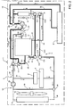
Figure 1 is a schematic illustration of a preferred embodiment of the air-conditioning system of the present invention installed on a motor vehicle; -
Figure 2 is similar toFigure 1 and illustrates the air-conditioning system ofFigure 1 in a different operating configuration; and -
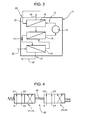
Figures 3 and 4 are schematic illustrations of respective details of the system ofFigures 1 and2 . - In
Figures 1 and2 , designated, as a whole, by 1 is a motor vehicle, in particular an electrically propelled automobile for transporting persons, which comprises, in a known way: anengine unit 2, in turn comprising one or more electric motors; amanagement unit 3, in turn comprising power and control electronic components for controlling theengine unit 2; and abattery pack 4. - The
motor vehicle 1 is moreover provided with an air-conditioning system, generally designated by 5, which has the function both of regulating the temperature and humidity of the air in the passenger compartment of themotor vehicle 1, bringing them to the desired values, and of maintaining the temperature of theengine unit 2 andmanagement unit 3 and of thebattery pack 4 around respective pre-set operating values. - The automotive air-
conditioning system 5 comprises: ahydraulic circuit 6, which is traversed by a carrier fluid, i.e., a heat-exchange fluid, preferably constituted by a mixture of water and glycol, and extends through aheat exchanger 7, which is set in the passenger compartment (not illustrated), normally underneath the dashboard (not illustrated), of themotor vehicle 1 and is associated to arespective fan 8 for heat exchange between the carrier fluid and the air of the passenger compartment and/or the external air and for supply, within the passenger compartment, of a flow of hot or cold air; a further heat exchanger 9, which normally constitutes the usual radiator arranged in an engine compartment (not illustrated) of themotor vehicle 1 and is associated to arespective fan 10 for heat exchange between the carrier fluid and the external air; and, finally, a compactthermal unit 11, in which a refrigerant fluid traverses a respective hydraulic circuit 12 (Figure 3 ) for carrying out a cycle of refrigeration and heat-exchange, in the way that will be explained in what follows, with the carrier fluid. - In particular, according to what is schematically illustrated in
Figure 1 , thehydraulic circuit 6 comprises twoportions portion 13 extends through theheat exchanger 7 and is designed for air-conditioning of the passenger compartment and for control in temperature of thebattery pack 4, and theportion 14 extends through the heat exchanger 9 and is designed for control in temperature of theengine unit 2 and of themanagement unit 3. - The
portions thermal unit 11 for subtracting or yielding heat from/to the passenger compartment and, respectively, for subtracting heat from theengine unit 2 andmanagement unit 3. - According to what is illustrated in
Figure 3 , thethermal unit 11 is of the known type described in the patent No.EP 1990221 , to which explicit reference is made herein, and is defined by an enbloc assembly normally housed in the engine compartment of themotor vehicle 1 and comprising, set in series along thehydraulic circuit 12, acompressor 15, a hot section, in the case in point in the form of acondenser 16, anexpansion valve 17, a cold section, in the case in point in the form of anevaporator 18, and, finally, anintermediate heat exchanger 19, set between thecondenser 16 and theexpansion valve 17. - According to a variant (not illustrated in the attached figures), the
compressor 15 is located outside of the enbloc assembly, which includes only the other components of the compactthermal unit 11, as illustrated inFigures 1 and2 ofEP 1990221 . - Heat exchange between the
thermal unit 11 and the carrier fluid that traverses theportions hydraulic circuit 6, in the case in point ahot portion 20 and acold portion 21, where thehot portion 20 extends through thecondenser 16 for cooling the refrigerant fluid and heating the carrier fluid, and thecold portion 21 extends through theevaporator 18 for heating the refrigerant fluid and cooling the carrier fluid. - The
hot portion 20 and thecold portion 21 are connected to the rest of thehydraulic circuit 6, i.e., to theportions valve device 22 designed to set theportion 13 in communication with thecold portion 21 and theportion 14 in communication with thehot portion 20, or, alternatively, theportion 13 in communication with thehot portion 20 and theportion 14 in communication with thecold portion 21. - In detail, according to what is illustrated in
Figures 1 and3 , thehot portion 20 comprises aninlet branch 23 and anoutlet branch 24 of thecondenser 16. Likewise, thecold portion 21 comprises aninlet branch 25 and anoutlet branch 26 of theevaporator 18. - According to what is illustrated schematically in
Figure 1 , thevalve device 22 comprises four valves, designated by V1, V2, V3, V4, each of which is provided with an inlet, designated by the letter I associated to the reference number of the respective valve, and an outlet, designated by the letter O associated to the reference number of the respective valve. Each inlet I is connected to the respective outlet O via a respective branch C, the branches being designated inFigures 1 and2 by the references C11, C22, C33, C44. - The valves V1 and V2 are in communication with one another via a branch C12, which connects the inlet I1 to the
outlet 02, and via a branch C21, which connects the inlet I2 to theoutlet 01. Likewise, the valves V3 and V4 are in communication with one another via a branch C34, which connects the inlet I3 to theoutlet 04, and via a branch C43, which connects the inlet I4 to theoutlet 03. - The
portion 13 of thecircuit 6 comprises aninlet branch 27, which extends, starting from the valve V4, through theheat exchanger 7 and gives out into avalve 28 connected to apump 29 via anintake branch 30. In turn, thepump 29 is connected to the valve V2 via adelivery branch 31. Theportion 13 further comprises a by-pass branch 32, which branches off from theinlet branch 27 downstream of theheat exchanger 7, extends through thebattery pack 4, and gives out into thevalve 28. Thevalve 28 is preferably defined by a two-way and two-position solenoid valve designed to set in communication theintake branch 30 with the by-pass branch 32 or with a terminal portion of theinlet branch 27. In other words, in a first position, thevalve 28 closes the outlet of the by-pass branch 32, and all the carrier fluid that has traversed theheat exchanger 7 is drawn in directly by thepump 29 without traversing thebattery pack 4; in a second position, thevalve 28 closes the outlet of theinlet branch 27, and all the carrier fluid that has traversed theheat exchanger 7 is forced, by suction of thepump 29, to flow through the by-pass branch 32 and thebattery pack 4 before reaching thepump 29. - The
portion 14 of thecircuit 6 comprises aninlet branch 33, which extends from the valve V3 to avalve 34 connected to apump 35 via anintake branch 36, which extends through the heat exchanger 9. In turn, thepump 35 is connected to the valve V1 via afirst delivery branch 37 and to theinlet branch 33 via asecond delivery branch 38, extending through theengine unit 2 and themanagement unit 3. Theportion 14 finally comprises a by-pass branch 39 of the heat exchanger 9. In particular, the by-pass branch 39 is set in parallel to theintake branch 36 and extends between thevalve 34 and a point of theintake branch 36 set upstream of thepump 35. - The
valve 34 is preferably defined by a two-way and two-position solenoid valve designed to set in communication a terminal portion of theinlet branch 33 with theintake branch 36 or with the by-pass branch 39. In other words, in a first position, thevalve 34 closes the inlet of the by-pass branch 39, and the carrier fluid coming from theinlet branch 33 and from thedelivery branch 38 reaches thepump 35 through theintake branch 36 and the heat exchanger 9. In a second position, thevalve 34 closes the inlet of theintake branch 36, and the carrier fluid coming from theinlet branch 33 and from thedelivery branch 38 reaches thepump 35 through the by-pass branch 39, without traversing the heat exchanger 9. - According to what is illustrated in
Figure 4 , thevalve device 22, which, for reasons of clarity, has been represented schematically inFigures 1 and2 by means of the four valves V1, V2, V3, V4, is defined, in actual fact, by a single valve assembly comprising two four-way and two-position solenoid valves V1-V2 and V3-V4 connected to one another by means of amechanical connection element 40, which renders them suitable for being actuated synchronously, via a single actuator associated to one of the two solenoid valves V1-V2 and V3-V4, so as to shift, against the action of a spring, between a first operating position (illustrated inFigure 4 ) and a second operating position. - In particular, the valves designated by V1 and V2 in
Figures 1 and2 constitute, as a whole, the solenoid valve V1-V2, and the branches C11, C22, C12 and C21 are virtual branches defined, in practice, by respective pipes made in the solenoid valve V1-V2 itself. Likewise, the valves designated by V3 and V4 inFigures 1 and2 constitute, as a whole, the solenoid valve V3-V4, and the branches C33, C44, C34 and C43 are virtual branches defined, in practice, by respective pipes made in the solenoid valve V3-V4 itself. According to a variant (not illustrated), themechanical connection element 40 is absent, and the solenoid valves V1-V2 and V3-V4 are independent of one another and are designed to be actuated synchronously by respective actuators. - Operation of the automotive air-
conditioning system 5 will be described in what follows with reference to two different operating configurations that the system can selectively assume: a first operating configuration, illustrated inFigure 1 , in which the system operates as system for cooling the passenger compartment, and a second operating configuration, illustrated inFigure 2 , in which the system operates as system for heating the passenger compartment. - In both of the operating configurations described above, the
thermal unit 11 functions by performing cyclically a refrigerating cycle of a known type. In the case in point, according to what is illustrated inFigure 3 , thecompressor 15 compresses the refrigerant fluid and supplies it, in the form of gas at high pressure and high temperature, to thecondenser 16, in which the refrigerant fluid condenses and yields heat to the carrier fluid that traverses thehot portion 20 of thehydraulic circuit 6. From thecondenser 16 the refrigerant fluid passes to theexpansion valve 17, where it undergoes a sharp drop in pressure before reaching theevaporator 18, in which the refrigerant fluid evaporates absorbing heat from the carrier fluid that traverses thecold portion 21 of thehydraulic circuit 6. From theevaporator 18, the refrigerant fluid returns to thecompressor 15 through theintermediate heat exchanger 19, in which the refrigerant fluid absorbs heat from the flow of refrigerant fluid that from thecondenser 16 flows towards theexpansion valve 17. - As regards what has been set forth above, it should be pointed out that the presence of the
intermediate heat exchanger 19 is not essential for operation of thethermal unit 11, and its function is that of improving the thermal yield of thethermal unit 11 itself. According to a more simplified variant (not illustrated) of the automotive air-conditioning system 5, thethermal unit 11 is without theintermediate heat exchanger 19. - To complete what has been set forth above, it should moreover be pointed out that the
thermal unit 11, which, in the example illustrated and described, is a vapour-compression thermal unit, can be replaced, without modifying operation of the automotive air-conditioning system 5, by a known thermal unit of a different nature and provided with a hot section designed to exchange heat with the carrier fluid via thehot portion 20, and a cold section designed to exchange heat with the carrier fluid via thecold portion 21. For example, according to variants not illustrated, thethermal unit 11 is constituted by a thermal unit with ejection cycle or else an absorption thermal unit or else a thermal unit with magnetic refrigeration, or else a thermal unit of any other nature. - According to what is illustrated in
Figure 1 , when the automotive air-conditioning system 5 operates as system for cooling the passenger compartment, for example in summer, thevalve device 22 is set in its first operating position (Figure 4 ), in which the inlet I of each valve V1, V2, V3, V4 is connected to the respective outlet O. In this way, theportion 13 is connected to thecold portion 21 via the branch C22 of the valve V2 and the branch C44 of the valve V4, and theportion 14 is connected to thehot portion 20 via the branch C11 of the valve V1 and the branch C33 of the valve V3. - It follows that the carrier fluid that circulates, under the thrust of the
pump 29, along theportion 13 and thecold portion 21 is cooled through theevaporator 18 and enables, through theheat exchanger 7 and therespective fan 8, supply of a flow of cold air inside the passenger compartment. - The
valve 28 of theportion 13 is controlled by a control unit (not illustrated) in such a way as to enable or otherwise passage of the carrier fluid along the by-pass branch 32 and through thebattery pack 4 according to whether the value of the temperature of thebattery pack 4 measured by a sensor (not illustrated) is higher or lower than a pre-set maximum value. - At the same time, the carrier fluid that circulates, under the thrust of the
pump 35, along theportion 14 and thehot portion 20 is able to remove heat from thecondenser 16 and from theengine unit 2 and themanagement unit 3 and to dissipate this heat outside themotor vehicle 1 through theheat exchanger 7 and therespective fan 8. - In this configuration, the
valve 34 is controlled by the control unit (not illustrated) in such a way as to close the inlet of the by-pass branch 39 and cause all the carrier fluid to flow along theintake branch 36 and through the heat exchanger 9. - According to what is illustrated in
Figure 2 , when the automotive air-conditioning system 5 operates as system for heating the passenger compartment, for example in winter, thevalve device 22 is set in its second operating position, in which the inlets I1, I3 of the valves V1 and V3 are connected, respectively, to theoutlet 02 of the valve V2 and to theoutlet 04 of the valve V4. In this way, theportion 13 is connected to thehot portion 20 via the branches C13 and C21, and theportion 14 is connected to thecold portion 21 via the branches C12 and C43. - It follows that the carrier fluid that circulates, under the thrust of the
pump 29, along theportion 13 and thehot portion 20 is able to remove heat from thecondenser 16 and to supply a flow of hot air inside the passenger compartment through theheat exchanger 7 and therespective fan 8. - In a way similar to what has been described previously, the
valve 28 of theportion 13 is controlled by the control unit (not illustrated) in such a way as to enable or otherwise passage of the carrier fluid along the by-pass branch 32 and through thebattery pack 4 according to whether the value of the temperature of thebattery pack 4 measured by the sensor (not illustrated) is lower than a pre-set minimum value or otherwise. - At the same time, the carrier fluid that circulates, under the thrust of the
pump 35, along theportion 14 and thecold portion 21 is cooled through theevaporator 18 and is able to remove the excess heat from theengine unit 2 andmanagement unit 3. - In this configuration, the
valve 34 is controlled by the control unit (not illustrated) in such a way as to close the inlet of theintake branch 36 and cause all the carrier fluid to flow along the by-pass branch 39. In this way, by preventing the carrier fluid from traversing the heat exchanger 9, heat exchange between the carrier fluid and the external air is prevented from cooling further the carrier fluid itself and even possibly causing freezing thereof. - To conclude what has been set forth above, it should be pointed out that modifications and variations may be made to what has been described and illustrated herein, without thereby departing from the sphere of protection of the present invention, as defined in the annexed claims.
- In particular, the automotive air-
conditioning system 5 described above is able to operate on a motor vehicle provided with internal-combustion engine or hybrid drive instead of an electric drive. In the case (not illustrated) of internal-combustion motor vehicle, theengine unit 2 comprises at least one internal-combustion engine and themotor vehicle 1 is without themanagement unit 3 and thebattery pack 4 and, consequently, the by-pass branch 28, which enables, in the example illustrated, cooling or heating thebattery pack 4.
Claims (13)
- An automotive air-conditioning system for a motor vehicle (1) having a passenger compartment and an engine unit (2); the system (5) comprising a thermal unit (11) provided with a hot section (16) and a cold section (18); and a hydraulic circuit (6), which is designed to be flown by a carrier fluid and comprises a first portion (13) provided with a first heat exchanger (7), a second portion (14) provided with a second heat exchanger (9), a third portion or hot portion (20) extending through said hot section (16), and a fourth portion or cold portion (21) extending through said cold section (18); the system (5) further comprising a valve device (22) designed to connect selectively either the hot portion (20) or the cold portion (21) with the first portion (13) and second portion (14) so as to set selectively the hydraulic circuit (6) in a first configuration, in which the first portion (13) is connected to the cold portion (21) and the second portion (14) is connected to the hot portion (20), and a second configuration, in which the first portion (13) is connected to the hot portion (20) and the second portion (14) is connected to the cold portion (21).
- The system according to Claim 1, wherein the first heat exchanger (7) is installed for exchanging heat between the carrier fluid and the air of the passenger compartment and/or the air external to the motor vehicle and supplying into the passenger compartment a flow of cold air in said first configuration, and a flow of hot air in said second configuration.
- The system according to Claim 1 or Claim 2, wherein the second portion (14) extends through the engine unit (2); the second heat exchanger (9) being designed, in the first configuration, to exchange heat between the carrier fluid and the air external to the motor vehicle so as to dissipate the heat removed from the engine unit (2) and from the hot section (16).
- The system according to Claim 3, wherein the second portion (14) comprises: a pump (35); a first delivery branch (37), which is connected to the hot portion (20) in the first configuration and to the cold portion (21) in the second configuration; a second delivery branch (38), which extends through the engine unit (2); and an intake branch (36), which extends through the second heat exchanger (9).
- The system according to Claim 4, wherein the second portion (14) comprises first by-pass means (34, 39) of the second heat exchanger (9), which in turn comprise a first by-pass branch (39) arranged in parallel to the intake branch (36), and a valve (34) operable to fluidically isolate the first by-pass branch (39) when the hydraulic circuit (6) is in the first configuration so as to cause the carrier fluid to flow only through the intake branch (36) and the second heat exchanger (9); the valve (34) being also operable to fluidically isolate the intake branch (36) and the second heat exchanger (9), when the hydraulic circuit (6) is in the second configuration so as to cause the carrier fluid to flow only through the first by-pass branch (39).
- An automotive air-conditioning system according to any one of Claims 3 to 5, wherein the motor vehicle (1) is an electric or hybrid motor vehicle and comprises a management unit (3) for managing power and control electronic components for controlling the engine unit (2); the second portion (14) extending through said management unit (3) for removing heat from the management unit (3) itself when the hydraulic circuit (6) is in the first configuration and in the second configuration.
- The system according to Claim 6, wherein the motor vehicle (1) comprises a battery pack (4); the first portion (13) comprising second means (28, 32) for by-pass of the battery pack (4) designed to cause the carrier fluid to flow or not through the battery pack (4) based on the temperature of the battery pack (4) with respect to a pre-set limit value.
- The system according to any one of the preceding claims, wherein the valve device (22) comprises two four-way, two-position solenoid valves (V1-V2, V3-V4).
- An automotive air-conditioning system according to Claim 8, wherein the two solenoid valves (V1-V2, V3-V4) are connected to one another by means of a mechanical connection element (40) so as to be actuated in a synchronous way by a single actuator.
- The system according to any one of the preceding claims, wherein the thermal unit (11) is a vapour-compression thermal unit, in which the hot section (16) comprises a condenser (16) and the cold section (18) comprises an evaporator (18); the thermal unit (11) further comprising a hydraulic refrigerating circuit (12) extending through the condenser (16) and the evaporator (18) and designed to be traversed by a refrigerant fluid.
- The system according to Claim 10, wherein the thermal unit (11) is an enbloc assembly designed to be housed in an engine compartment of the motor vehicle.
- The system according to Claim 10 or Claim 11, wherein the hydraulic refrigerating circuit (12) comprises an intermediate heat exchanger (19) designed to enable a heat exchange between the refrigerant fluid leaving the evaporator (18) and the refrigerant fluid leaving the condenser (16).
- A motor vehicle comprising an automotive air-conditioning system (5) according to any one of the preceding claims.
Priority Applications (2)
| Application Number | Priority Date | Filing Date | Title |
|---|---|---|---|
| EP10425244A EP2409864B1 (en) | 2010-07-19 | 2010-07-19 | Automotive air-conditioning system |
| US13/185,956 US8635882B2 (en) | 2010-07-19 | 2011-07-19 | Automotive air-conditioning system |
Applications Claiming Priority (1)
| Application Number | Priority Date | Filing Date | Title |
|---|---|---|---|
| EP10425244A EP2409864B1 (en) | 2010-07-19 | 2010-07-19 | Automotive air-conditioning system |
Publications (2)
| Publication Number | Publication Date |
|---|---|
| EP2409864A1 true EP2409864A1 (en) | 2012-01-25 |
| EP2409864B1 EP2409864B1 (en) | 2013-03-27 |
Family
ID=42985436
Family Applications (1)
| Application Number | Title | Priority Date | Filing Date |
|---|---|---|---|
| EP10425244A Revoked EP2409864B1 (en) | 2010-07-19 | 2010-07-19 | Automotive air-conditioning system |
Country Status (2)
| Country | Link |
|---|---|
| US (1) | US8635882B2 (en) |
| EP (1) | EP2409864B1 (en) |
Cited By (3)
| Publication number | Priority date | Publication date | Assignee | Title |
|---|---|---|---|---|
| EP3023275A4 (en) * | 2013-07-17 | 2017-04-05 | Panasonic Intellectual Property Management Co., Ltd. | Vehicle air conditioner and constituent unit thereof |
| WO2018009122A1 (en) * | 2016-07-07 | 2018-01-11 | Scania Cv Ab | A cooling system in a hybrid vehicle |
| US20190152343A1 (en) * | 2017-11-17 | 2019-05-23 | Aisin Seiki Kabushiki Kaisha | Vehicular heat exchange device |
Families Citing this family (10)
| Publication number | Priority date | Publication date | Assignee | Title |
|---|---|---|---|---|
| FR2987315B1 (en) * | 2012-02-24 | 2014-03-07 | Valeo Systemes Thermiques | DEVICE FOR THERMALLY CONDITIONING A CAR AND A TRACTION CHAIN OF A VEHICLE. |
| JP6252186B2 (en) * | 2014-01-15 | 2017-12-27 | 株式会社デンソー | Thermal management system for vehicles |
| US10718256B2 (en) * | 2016-05-03 | 2020-07-21 | GM Global Technology Operations LLC | Powertrain thermal management system and method |
| JP6465082B2 (en) * | 2016-07-29 | 2019-02-06 | トヨタ自動車株式会社 | Vehicle structure |
| EP3623183B1 (en) * | 2018-09-11 | 2020-12-02 | C.R.F. Società Consortile per Azioni | A system for thermal management of the components of a hybrid vehicle |
| KR102633864B1 (en) * | 2018-12-06 | 2024-02-05 | 현대자동차 주식회사 | Betterly cooling system for vehicle |
| KR102633867B1 (en) * | 2018-12-10 | 2024-02-05 | 현대자동차 주식회사 | Heat pump system for vehicle |
| KR102909372B1 (en) * | 2020-10-12 | 2026-01-07 | 현대자동차 주식회사 | Thermal management system for vehicle |
| KR102952379B1 (en) * | 2020-12-07 | 2026-04-13 | 현대자동차주식회사 | Integrated thermal management system for vehicle |
| EP4269140B1 (en) * | 2022-04-29 | 2024-06-12 | Volvo Car Corporation | Temperature control system for a vehicle and method for operating a temperature control system for a vehicle |
Citations (5)
| Publication number | Priority date | Publication date | Assignee | Title |
|---|---|---|---|---|
| EP1329344A1 (en) * | 2002-01-16 | 2003-07-23 | Renault s.a.s. | Device for thermal management, especially for a vehicle equipped with a fuel cell |
| US20040035130A1 (en) * | 2000-05-15 | 2004-02-26 | Manuel Amaral | Heat control device for motor vehicle and methods using same |
| US20040134217A1 (en) * | 2003-01-09 | 2004-07-15 | Satoshi Itoh | Air conditioner with dehumidifying and heating operation |
| EP1719646A1 (en) * | 2005-05-03 | 2006-11-08 | C.R.F. Società Consortile per Azioni | An air-conditioning system for a motor vehicle, in particular a bus, and a motor vehicle provided with said system |
| EP1990221A1 (en) * | 2007-05-10 | 2008-11-12 | C.R.F. Società Consortile Per Azioni | Air-conditioning system for a motor vehicle, and motor vehicle equipped with the system |
Family Cites Families (10)
| Publication number | Priority date | Publication date | Assignee | Title |
|---|---|---|---|---|
| US1506531A (en) * | 1921-12-12 | 1924-08-26 | Westinghouse Electric & Mfg Co | Refrigeration apparatus |
| BE568438A (en) * | 1957-06-12 | |||
| US6038877A (en) * | 1998-05-22 | 2000-03-21 | Bergstrom, Inc. | Modular low pressure delivery vehicle air conditioning system |
| US6457324B2 (en) * | 1998-05-22 | 2002-10-01 | Bergstrom, Inc. | Modular low-pressure delivery vehicle air conditioning system having an in-cab cool box |
| US6272867B1 (en) * | 1999-09-22 | 2001-08-14 | The Coca-Cola Company | Apparatus using stirling cooler system and methods of use |
| WO2002012800A1 (en) * | 2000-08-09 | 2002-02-14 | Astronautics Corporation Of America | Rotating bed magnetic refrigeration apparatus |
| CN1330922C (en) * | 2002-01-22 | 2007-08-08 | 汉尼·迪那 | Heat pipe loop with pump assistance |
| DE10259071B4 (en) * | 2002-07-16 | 2006-05-04 | J. Eberspächer GmbH & Co. KG | Temperature control system for a vehicle |
| US7971601B2 (en) * | 2007-07-02 | 2011-07-05 | Grundfos Pumps Corporation | Water circulation system valve assemblies having water temperature control |
| US8318370B2 (en) * | 2009-03-31 | 2012-11-27 | Keogh Rory C | Periodic flow heat exchanger |
-
2010
- 2010-07-19 EP EP10425244A patent/EP2409864B1/en not_active Revoked
-
2011
- 2011-07-19 US US13/185,956 patent/US8635882B2/en active Active
Patent Citations (5)
| Publication number | Priority date | Publication date | Assignee | Title |
|---|---|---|---|---|
| US20040035130A1 (en) * | 2000-05-15 | 2004-02-26 | Manuel Amaral | Heat control device for motor vehicle and methods using same |
| EP1329344A1 (en) * | 2002-01-16 | 2003-07-23 | Renault s.a.s. | Device for thermal management, especially for a vehicle equipped with a fuel cell |
| US20040134217A1 (en) * | 2003-01-09 | 2004-07-15 | Satoshi Itoh | Air conditioner with dehumidifying and heating operation |
| EP1719646A1 (en) * | 2005-05-03 | 2006-11-08 | C.R.F. Società Consortile per Azioni | An air-conditioning system for a motor vehicle, in particular a bus, and a motor vehicle provided with said system |
| EP1990221A1 (en) * | 2007-05-10 | 2008-11-12 | C.R.F. Società Consortile Per Azioni | Air-conditioning system for a motor vehicle, and motor vehicle equipped with the system |
Cited By (4)
| Publication number | Priority date | Publication date | Assignee | Title |
|---|---|---|---|---|
| EP3023275A4 (en) * | 2013-07-17 | 2017-04-05 | Panasonic Intellectual Property Management Co., Ltd. | Vehicle air conditioner and constituent unit thereof |
| WO2018009122A1 (en) * | 2016-07-07 | 2018-01-11 | Scania Cv Ab | A cooling system in a hybrid vehicle |
| US20190152343A1 (en) * | 2017-11-17 | 2019-05-23 | Aisin Seiki Kabushiki Kaisha | Vehicular heat exchange device |
| US10829005B2 (en) * | 2017-11-17 | 2020-11-10 | Aisin Seiki Kabushiki Kaisha | Vehicular heat exchange device |
Also Published As
| Publication number | Publication date |
|---|---|
| US8635882B2 (en) | 2014-01-28 |
| EP2409864B1 (en) | 2013-03-27 |
| US20120180980A1 (en) | 2012-07-19 |
Similar Documents
| Publication | Publication Date | Title |
|---|---|---|
| US8635882B2 (en) | Automotive air-conditioning system | |
| EP2301777B1 (en) | Method for controlling the passenger compartment temperature of an electrically operated vehicle and air-conditioning system | |
| EP4151440B1 (en) | Heat management system | |
| EP2676086B1 (en) | A unitary heat pump air conditioner | |
| US20140060102A1 (en) | Mild ambient vehicular heat pump system | |
| CN107020921B (en) | Vehicle cabin air conditioner and battery cooling system | |
| JP6047314B2 (en) | Air conditioner for vehicles | |
| EP2524830B1 (en) | Air conditioning system for vehicle | |
| US9016080B2 (en) | Battery heating and cooling system | |
| US9908383B2 (en) | Air conditioning system for a motor vehicle | |
| KR101558823B1 (en) | Air conditioning system for controlling the temperature of components and of an interior of a motor vehicle | |
| EP2972019B1 (en) | A unitary heat pump air conditioner having a compressed vapor diversion loop | |
| JP5003639B2 (en) | Vehicle cooling system | |
| CN215284271U (en) | New energy hybrid vehicle type cab and power battery integrated thermal management system | |
| CN112428767B (en) | Vehicle thermal management system | |
| JP2009257748A (en) | Heating and air-conditioning unit for automobile | |
| CN221090418U (en) | Indirect heat pump thermal management system and vehicle | |
| CN204586420U (en) | Vehicle and a/c system thereof | |
| CN105758061B (en) | Vehicles and their air conditioning systems | |
| CN115891555B (en) | Thermal management system and control method thereof | |
| CN120816868A (en) | A new energy vehicle heat pump system | |
| CN120840329A (en) | Thermal Management System | |
| CN212579558U (en) | Temperature control governing system in electric motor car | |
| CN111439090B (en) | Temperature control and regulation system in electric vehicle | |
| CN116834497A (en) | thermal management system |
Legal Events
| Date | Code | Title | Description |
|---|---|---|---|
| 17P | Request for examination filed |
Effective date: 20110406 |
|
| AK | Designated contracting states |
Kind code of ref document: A1 Designated state(s): AL AT BE BG CH CY CZ DE DK EE ES FI FR GB GR HR HU IE IS IT LI LT LU LV MC MK MT NL NO PL PT RO SE SI SK SM TR |
|
| AX | Request for extension of the european patent |
Extension state: BA ME RS |
|
| PUAI | Public reference made under article 153(3) epc to a published international application that has entered the european phase |
Free format text: ORIGINAL CODE: 0009012 |
|
| GRAP | Despatch of communication of intention to grant a patent |
Free format text: ORIGINAL CODE: EPIDOSNIGR1 |
|
| GRAS | Grant fee paid |
Free format text: ORIGINAL CODE: EPIDOSNIGR3 |
|
| GRAA | (expected) grant |
Free format text: ORIGINAL CODE: 0009210 |
|
| RIN1 | Information on inventor provided before grant (corrected) |
Inventor name: MALVICINO, CARLOANDREA Inventor name: ROSTAGNO, MATTEO |
|
| AK | Designated contracting states |
Kind code of ref document: B1 Designated state(s): AL AT BE BG CH CY CZ DE DK EE ES FI FR GB GR HR HU IE IS IT LI LT LU LV MC MK MT NL NO PL PT RO SE SI SK SM TR |
|
| REG | Reference to a national code |
Ref country code: GB Ref legal event code: FG4D |
|
| REG | Reference to a national code |
Ref country code: CH Ref legal event code: EP |
|
| REG | Reference to a national code |
Ref country code: AT Ref legal event code: REF Ref document number: 603144 Country of ref document: AT Kind code of ref document: T Effective date: 20130415 |
|
| REG | Reference to a national code |
Ref country code: IE Ref legal event code: FG4D |
|
| REG | Reference to a national code |
Ref country code: DE Ref legal event code: R096 Ref document number: 602010005801 Country of ref document: DE Effective date: 20130516 |
|
| REG | Reference to a national code |
Ref country code: DE Ref legal event code: R082 Ref document number: 602010005801 Country of ref document: DE |
|
| PG25 | Lapsed in a contracting state [announced via postgrant information from national office to epo] |
Ref country code: SE Free format text: LAPSE BECAUSE OF FAILURE TO SUBMIT A TRANSLATION OF THE DESCRIPTION OR TO PAY THE FEE WITHIN THE PRESCRIBED TIME-LIMIT Effective date: 20130327 Ref country code: BG Free format text: LAPSE BECAUSE OF FAILURE TO SUBMIT A TRANSLATION OF THE DESCRIPTION OR TO PAY THE FEE WITHIN THE PRESCRIBED TIME-LIMIT Effective date: 20130627 Ref country code: LT Free format text: LAPSE BECAUSE OF FAILURE TO SUBMIT A TRANSLATION OF THE DESCRIPTION OR TO PAY THE FEE WITHIN THE PRESCRIBED TIME-LIMIT Effective date: 20130327 Ref country code: NO Free format text: LAPSE BECAUSE OF FAILURE TO SUBMIT A TRANSLATION OF THE DESCRIPTION OR TO PAY THE FEE WITHIN THE PRESCRIBED TIME-LIMIT Effective date: 20130627 |
|
| REG | Reference to a national code |
Ref country code: AT Ref legal event code: MK05 Ref document number: 603144 Country of ref document: AT Kind code of ref document: T Effective date: 20130327 |
|
| REG | Reference to a national code |
Ref country code: LT Ref legal event code: MG4D |
|
| PG25 | Lapsed in a contracting state [announced via postgrant information from national office to epo] |
Ref country code: GR Free format text: LAPSE BECAUSE OF FAILURE TO SUBMIT A TRANSLATION OF THE DESCRIPTION OR TO PAY THE FEE WITHIN THE PRESCRIBED TIME-LIMIT Effective date: 20130628 Ref country code: LV Free format text: LAPSE BECAUSE OF FAILURE TO SUBMIT A TRANSLATION OF THE DESCRIPTION OR TO PAY THE FEE WITHIN THE PRESCRIBED TIME-LIMIT Effective date: 20130327 Ref country code: SI Free format text: LAPSE BECAUSE OF FAILURE TO SUBMIT A TRANSLATION OF THE DESCRIPTION OR TO PAY THE FEE WITHIN THE PRESCRIBED TIME-LIMIT Effective date: 20130327 Ref country code: FI Free format text: LAPSE BECAUSE OF FAILURE TO SUBMIT A TRANSLATION OF THE DESCRIPTION OR TO PAY THE FEE WITHIN THE PRESCRIBED TIME-LIMIT Effective date: 20130327 |
|
| REG | Reference to a national code |
Ref country code: NL Ref legal event code: VDEP Effective date: 20130327 |
|
| PG25 | Lapsed in a contracting state [announced via postgrant information from national office to epo] |
Ref country code: HR Free format text: LAPSE BECAUSE OF FAILURE TO SUBMIT A TRANSLATION OF THE DESCRIPTION OR TO PAY THE FEE WITHIN THE PRESCRIBED TIME-LIMIT Effective date: 20130327 Ref country code: BE Free format text: LAPSE BECAUSE OF FAILURE TO SUBMIT A TRANSLATION OF THE DESCRIPTION OR TO PAY THE FEE WITHIN THE PRESCRIBED TIME-LIMIT Effective date: 20130327 |
|
| PG25 | Lapsed in a contracting state [announced via postgrant information from national office to epo] |
Ref country code: CZ Free format text: LAPSE BECAUSE OF FAILURE TO SUBMIT A TRANSLATION OF THE DESCRIPTION OR TO PAY THE FEE WITHIN THE PRESCRIBED TIME-LIMIT Effective date: 20130327 Ref country code: ES Free format text: LAPSE BECAUSE OF FAILURE TO SUBMIT A TRANSLATION OF THE DESCRIPTION OR TO PAY THE FEE WITHIN THE PRESCRIBED TIME-LIMIT Effective date: 20130708 Ref country code: AT Free format text: LAPSE BECAUSE OF FAILURE TO SUBMIT A TRANSLATION OF THE DESCRIPTION OR TO PAY THE FEE WITHIN THE PRESCRIBED TIME-LIMIT Effective date: 20130327 Ref country code: IS Free format text: LAPSE BECAUSE OF FAILURE TO SUBMIT A TRANSLATION OF THE DESCRIPTION OR TO PAY THE FEE WITHIN THE PRESCRIBED TIME-LIMIT Effective date: 20130727 Ref country code: EE Free format text: LAPSE BECAUSE OF FAILURE TO SUBMIT A TRANSLATION OF THE DESCRIPTION OR TO PAY THE FEE WITHIN THE PRESCRIBED TIME-LIMIT Effective date: 20130327 Ref country code: SK Free format text: LAPSE BECAUSE OF FAILURE TO SUBMIT A TRANSLATION OF THE DESCRIPTION OR TO PAY THE FEE WITHIN THE PRESCRIBED TIME-LIMIT Effective date: 20130327 Ref country code: PT Free format text: LAPSE BECAUSE OF FAILURE TO SUBMIT A TRANSLATION OF THE DESCRIPTION OR TO PAY THE FEE WITHIN THE PRESCRIBED TIME-LIMIT Effective date: 20130729 Ref country code: RO Free format text: LAPSE BECAUSE OF FAILURE TO SUBMIT A TRANSLATION OF THE DESCRIPTION OR TO PAY THE FEE WITHIN THE PRESCRIBED TIME-LIMIT Effective date: 20130327 Ref country code: NL Free format text: LAPSE BECAUSE OF FAILURE TO SUBMIT A TRANSLATION OF THE DESCRIPTION OR TO PAY THE FEE WITHIN THE PRESCRIBED TIME-LIMIT Effective date: 20130327 |
|
| PG25 | Lapsed in a contracting state [announced via postgrant information from national office to epo] |
Ref country code: CY Free format text: LAPSE BECAUSE OF FAILURE TO SUBMIT A TRANSLATION OF THE DESCRIPTION OR TO PAY THE FEE WITHIN THE PRESCRIBED TIME-LIMIT Effective date: 20130327 Ref country code: PL Free format text: LAPSE BECAUSE OF FAILURE TO SUBMIT A TRANSLATION OF THE DESCRIPTION OR TO PAY THE FEE WITHIN THE PRESCRIBED TIME-LIMIT Effective date: 20130327 |
|
| PLBI | Opposition filed |
Free format text: ORIGINAL CODE: 0009260 |
|
| PG25 | Lapsed in a contracting state [announced via postgrant information from national office to epo] |
Ref country code: DK Free format text: LAPSE BECAUSE OF FAILURE TO SUBMIT A TRANSLATION OF THE DESCRIPTION OR TO PAY THE FEE WITHIN THE PRESCRIBED TIME-LIMIT Effective date: 20130327 |
|
| PLAX | Notice of opposition and request to file observation + time limit sent |
Free format text: ORIGINAL CODE: EPIDOSNOBS2 |
|
| 26 | Opposition filed |
Opponent name: MAHLE INTERNATIONAL GMBH Effective date: 20131217 |
|
| PG25 | Lapsed in a contracting state [announced via postgrant information from national office to epo] |
Ref country code: MC Free format text: LAPSE BECAUSE OF FAILURE TO SUBMIT A TRANSLATION OF THE DESCRIPTION OR TO PAY THE FEE WITHIN THE PRESCRIBED TIME-LIMIT Effective date: 20130327 |
|
| REG | Reference to a national code |
Ref country code: DE Ref legal event code: R026 Ref document number: 602010005801 Country of ref document: DE Effective date: 20131217 |
|
| REG | Reference to a national code |
Ref country code: IE Ref legal event code: MM4A |
|
| PLBB | Reply of patent proprietor to notice(s) of opposition received |
Free format text: ORIGINAL CODE: EPIDOSNOBS3 |
|
| PG25 | Lapsed in a contracting state [announced via postgrant information from national office to epo] |
Ref country code: IE Free format text: LAPSE BECAUSE OF NON-PAYMENT OF DUE FEES Effective date: 20130719 |
|
| REG | Reference to a national code |
Ref country code: CH Ref legal event code: PL |
|
| GBPC | Gb: european patent ceased through non-payment of renewal fee |
Effective date: 20140719 |
|
| PG25 | Lapsed in a contracting state [announced via postgrant information from national office to epo] |
Ref country code: CH Free format text: LAPSE BECAUSE OF NON-PAYMENT OF DUE FEES Effective date: 20140731 Ref country code: LI Free format text: LAPSE BECAUSE OF NON-PAYMENT OF DUE FEES Effective date: 20140731 |
|
| PG25 | Lapsed in a contracting state [announced via postgrant information from national office to epo] |
Ref country code: GB Free format text: LAPSE BECAUSE OF NON-PAYMENT OF DUE FEES Effective date: 20140719 Ref country code: SM Free format text: LAPSE BECAUSE OF FAILURE TO SUBMIT A TRANSLATION OF THE DESCRIPTION OR TO PAY THE FEE WITHIN THE PRESCRIBED TIME-LIMIT Effective date: 20130327 |
|
| PG25 | Lapsed in a contracting state [announced via postgrant information from national office to epo] |
Ref country code: TR Free format text: LAPSE BECAUSE OF FAILURE TO SUBMIT A TRANSLATION OF THE DESCRIPTION OR TO PAY THE FEE WITHIN THE PRESCRIBED TIME-LIMIT Effective date: 20130327 Ref country code: MT Free format text: LAPSE BECAUSE OF FAILURE TO SUBMIT A TRANSLATION OF THE DESCRIPTION OR TO PAY THE FEE WITHIN THE PRESCRIBED TIME-LIMIT Effective date: 20130327 |
|
| PG25 | Lapsed in a contracting state [announced via postgrant information from national office to epo] |
Ref country code: HU Free format text: LAPSE BECAUSE OF FAILURE TO SUBMIT A TRANSLATION OF THE DESCRIPTION OR TO PAY THE FEE WITHIN THE PRESCRIBED TIME-LIMIT; INVALID AB INITIO Effective date: 20100719 Ref country code: LU Free format text: LAPSE BECAUSE OF NON-PAYMENT OF DUE FEES Effective date: 20130719 Ref country code: MK Free format text: LAPSE BECAUSE OF FAILURE TO SUBMIT A TRANSLATION OF THE DESCRIPTION OR TO PAY THE FEE WITHIN THE PRESCRIBED TIME-LIMIT Effective date: 20130327 |
|
| APAH | Appeal reference modified |
Free format text: ORIGINAL CODE: EPIDOSCREFNO |
|
| APBM | Appeal reference recorded |
Free format text: ORIGINAL CODE: EPIDOSNREFNO |
|
| APBP | Date of receipt of notice of appeal recorded |
Free format text: ORIGINAL CODE: EPIDOSNNOA2O |
|
| APBQ | Date of receipt of statement of grounds of appeal recorded |
Free format text: ORIGINAL CODE: EPIDOSNNOA3O |
|
| REG | Reference to a national code |
Ref country code: FR Ref legal event code: PLFP Year of fee payment: 7 |
|
| REG | Reference to a national code |
Ref country code: FR Ref legal event code: PLFP Year of fee payment: 8 |
|
| REG | Reference to a national code |
Ref country code: FR Ref legal event code: PLFP Year of fee payment: 9 |
|
| REG | Reference to a national code |
Ref country code: DE Ref legal event code: R064 Ref document number: 602010005801 Country of ref document: DE Ref country code: DE Ref legal event code: R103 Ref document number: 602010005801 Country of ref document: DE |
|
| APBU | Appeal procedure closed |
Free format text: ORIGINAL CODE: EPIDOSNNOA9O |
|
| PG25 | Lapsed in a contracting state [announced via postgrant information from national office to epo] |
Ref country code: AL Free format text: LAPSE BECAUSE OF FAILURE TO SUBMIT A TRANSLATION OF THE DESCRIPTION OR TO PAY THE FEE WITHIN THE PRESCRIBED TIME-LIMIT Effective date: 20130327 |
|
| PGFP | Annual fee paid to national office [announced via postgrant information from national office to epo] |
Ref country code: IT Payment date: 20180712 Year of fee payment: 9 Ref country code: FR Payment date: 20180726 Year of fee payment: 9 |
|
| RDAF | Communication despatched that patent is revoked |
Free format text: ORIGINAL CODE: EPIDOSNREV1 |
|
| RDAG | Patent revoked |
Free format text: ORIGINAL CODE: 0009271 |
|
| 27W | Patent revoked |
Effective date: 20181026 |
|
| PGFP | Annual fee paid to national office [announced via postgrant information from national office to epo] |
Ref country code: DE Payment date: 20180928 Year of fee payment: 9 |