EP2409655A2 - False lumen occluder - Google Patents
False lumen occluder Download PDFInfo
- Publication number
- EP2409655A2 EP2409655A2 EP11174324A EP11174324A EP2409655A2 EP 2409655 A2 EP2409655 A2 EP 2409655A2 EP 11174324 A EP11174324 A EP 11174324A EP 11174324 A EP11174324 A EP 11174324A EP 2409655 A2 EP2409655 A2 EP 2409655A2
- Authority
- EP
- European Patent Office
- Prior art keywords
- struts
- intraluminal device
- strut portion
- mid
- strut
- Prior art date
- Legal status (The legal status is an assumption and is not a legal conclusion. Google has not performed a legal analysis and makes no representation as to the accuracy of the status listed.)
- Granted
Links
Images







Classifications
-
- A—HUMAN NECESSITIES
- A61—MEDICAL OR VETERINARY SCIENCE; HYGIENE
- A61B—DIAGNOSIS; SURGERY; IDENTIFICATION
- A61B17/00—Surgical instruments, devices or methods
- A61B17/12—Surgical instruments, devices or methods for ligaturing or otherwise compressing tubular parts of the body, e.g. blood vessels or umbilical cord
- A61B17/12022—Occluding by internal devices, e.g. balloons or releasable wires
-
- A—HUMAN NECESSITIES
- A61—MEDICAL OR VETERINARY SCIENCE; HYGIENE
- A61B—DIAGNOSIS; SURGERY; IDENTIFICATION
- A61B17/00—Surgical instruments, devices or methods
- A61B17/12—Surgical instruments, devices or methods for ligaturing or otherwise compressing tubular parts of the body, e.g. blood vessels or umbilical cord
- A61B17/12022—Occluding by internal devices, e.g. balloons or releasable wires
- A61B17/12099—Occluding by internal devices, e.g. balloons or releasable wires characterised by the location of the occluder
- A61B17/12109—Occluding by internal devices, e.g. balloons or releasable wires characterised by the location of the occluder in a blood vessel
- A61B17/12113—Occluding by internal devices, e.g. balloons or releasable wires characterised by the location of the occluder in a blood vessel within an aneurysm
-
- A—HUMAN NECESSITIES
- A61—MEDICAL OR VETERINARY SCIENCE; HYGIENE
- A61B—DIAGNOSIS; SURGERY; IDENTIFICATION
- A61B17/00—Surgical instruments, devices or methods
- A61B17/12—Surgical instruments, devices or methods for ligaturing or otherwise compressing tubular parts of the body, e.g. blood vessels or umbilical cord
- A61B17/12022—Occluding by internal devices, e.g. balloons or releasable wires
- A61B17/12131—Occluding by internal devices, e.g. balloons or releasable wires characterised by the type of occluding device
- A61B17/12168—Occluding by internal devices, e.g. balloons or releasable wires characterised by the type of occluding device having a mesh structure
- A61B17/12172—Occluding by internal devices, e.g. balloons or releasable wires characterised by the type of occluding device having a mesh structure having a pre-set deployed three-dimensional shape
Definitions
- Aortic dissection is a condition that affects the aorta, which is the largest artery in the body. This condition is caused by the separating/dissection of the individual layers of the aorta, where the inner layer of the aortic wall tears, or peels, away from the adjacent layer of the aorta. This separation of the layers creates an area, or a pathway, between the tom-away layer and the remainder of the aortic wall. The area created by the two layers is called a false lumen. As blood flows through the aorta, it travels through its normal pathway, referred to as the true lumen, but a portion of the blood also is directed into the false lumen.
- the false lumen is a secondary flow path that does not provide any blood delivery to the remainder of the body.
- the rate of blood flow and volume of diverted blood into the false lumen can result in the exertion of large forces against the aortic wall. These forces result in the further propagation of the tear, thereby creating a larger false lumen and greater associated forces. The propagation of the tear can eventually lead the aorta wall to rupture, which can result in death.
- the type of treatment for this condition depends on the severity and location of the aortic tear.
- Medical therapy such as blood pressure and cholesterol-lowering drugs, are typically provided as one method of treatment for this condition. Medical therapy is designed to limit further propagation of the tear and to reduce the chances of aortic rupture. This type of treatment is adequate when the condition is in its early stages and no significant tear exists. However, it is not designed to prevent the further propagation of a dissected portion of the aortic wall.
- Endovascular intervention is a minimally invasive procedure where a stent graft is placed within the damaged area. When expanded, the stent graft exerts a radial force along the damaged area, thereby forcing the dissected layer of the aorta against the adjacent layer of the aortic wall. In theory, retaining the dissected layer of the aorta against the adjacent layer of the aortic wall prevents blood from flowing into the dissected layer, thereby minimizing the blood flow into the false lumen.
- This type of treatment only covers the dissected layer and sometimes does not fully occlude the false lumen formed between the dissected layer and the adjacent layer of the aortic wall.
- This type of treatment is typically in chronic aortic dissection cases, there is a likelihood that blood will continue to flow between the dissected layer and the adjacent aortic layer, thereby causing the dissected portion of the aortic wall to further separate from the adjacent layer of the aortic wall which allows additional blood to reenter the false lumen.
- Another disadvantage of this type of treatment is that it does not prevent the chances of future tears in the damaged area. As a result, endovascular repair is an inadequate method of treatment for patients suffering from chronic aortic dissection.
- Open surgical repair is another type of treatment used to cure aortic dissection.
- This highly invasive procedure requires the replacement of the diseased portion of the aorta with a Dacron/ePTFE graft.
- the graft is sewn in the place of the removed portion of the aorta and on average requires a two-month recovery period.
- open surgical repair is a lengthy procedure and subjects patients to a higher risk for stroke, ischemia, and other medical complications. As a result, this type of procedure is not recommended to treat aortic dissection cases unless no other treatment is available and carries a high likelihood of post-surgical complications.
- the intraluminal device comprises a first end, a second end, and a central longitudinal axis between the first and second ends and expanded and compressed configurations, where a plurality of struts extend from the first to second end of the intraluminal device with at least one of the struts having a proximal strut portion, a distal strut portion, and a mid-strut portion between the proximal strut portion and the distal strut portion, where the mid-strut portion has at least two struts, and when the intraluminal device is in the expanded configuration, the plurality of struts are biased away from the longitudinal axis.
- the intraluminal device comprises a first end, a second end, and a central longitudinal axis between the first and second ends and a expanded and compressed configurations, where a plurality of struts made from the same piece of material extend from the first to second end of the intraluminal device with at least one of the struts having a proximal strut portion, a distal strut portion, and a mid-strut portion between the proximal strut portion and the distal strut portion, where the mid-strut portion has at least two struts, and when the intraluminal device is in the expanded configuration, the plurality of struts are biased away from the longitudinal axis and the at least two struts of the mid-strut portion have an arcuate shape.
- the intraluminal device comprises a first end, a second end, and a central longitudinal axis between the first and second ends and expanded and compressed configurations, where a plurality of struts made from the same piece of material extend from the first to second end of the intraluminal device with at least one of the struts having a proximal strut portion, a distal strut portion, and a mid-strut portion between the proximal strut portion and the distal strut portion, where the mid-strut portion has at least two struts made out of the same material as the plurality of struts, and when the intraluminal device is in the expanded configuration, the plurality of struts are biased away from the longitudinal axis and the at least two struts of the mid-strut portion have an arcuate shape.
- the length of each of the at least two struts of the mid-strut portion may be approximately equal to one half of the overall length of the at least one of
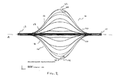
- Figure 1 shows a side view of one embodiment of an intraluminal device having a plurality of struts in an expanded configuration.
- Figure 2 shows a side view the intraluminal device shown in Figure 1 in a compressed configuration.
- Figure 3 shows a front view of the intraluminal device shown in Figure 1 when in the compressed configuration.
- Figure 4 shows a front view of the intraluminal device shown in Figure 1 when in the expanded configuration.
- Figure 5 shows another embodiment of the intraluminal device having a plurality of independent struts in an expanded configuration.
- Figure 6 shows a cross-sectional view of a false lumen within the aorta.
- Figure 7 shows one embodiment of a deployment device for the intraluminal device.
- Figure 8 shows another embodiment of the deployment device of the intraluminal device.
- Figure 9 shows the deployment device entering a vessel and a false lumen within the aorta.
- Figure 10 shows the deployment of the intraluminal device within the false lumen shown in Figure 9 .
- Figure 11 shows the intraluminal device secured within the false lumen shown in Figure 9 .
- Figure 12 shows the intraluminal device in a compressed configuration within the false lumen shown in Figure 9 .
- Figure 13 shows another embodiment of the intraluminal device wrapped in a membrane.
- distal with respect to such a device, or false lumen occluder, is intended to refer to a location that is, or a portion of the device that when implanted, is further downstream with respect to blood flow; the term “distally” means in the direction of blood flow or further downstream.
- proximal is intended to refer to a location that is, or a portion of the device that when implanted is, further upstream with respect to blood flow; the term “proximally” means in the direction opposite to the direction of blood flow or further upstream.
- intraluminal describes objects that are found or can be placed inside a lumen in the human or animal body.
- a lumen can be an existing lumen or a lumen created by surgical intervention. This includes lumens such as blood vessels, such as an aorta, parts of the gastrointestinal tract, ducts such as bile ducts, parts of the respiratory system, etcetera.
- “Intraluminal device” is thus a device that can be placed inside one of these lumens.
- An expandable device having a plurality of struts is a type of intraluminal device.
- This invention relates to an intraluminal device having a plurality of struts extending from a first end of the device to the second end of the device. Along at least one of the struts is a mid-strut portion having two secondary struts.
- the method of delivery and placement of the intraluminal device within a lumen is also part of the invention described herein.
- an intraluminal device 10 in an expanded configuration is shown.
- the intraluminal device 10 includes a first end 12 and a second end 14, where the first end 12 and second end 14 are along a central longitudinal axis A.
- a plurality of struts 16 extend from the first end 12 to the second end 14 and are made out of a single piece of material.
- Each of the plurality of struts 16 include a proximal portion 18 that is adjacent to the first end 12 and a distal portion 20 that is adjacent to the second end 14 of the intraluminal device 10.
- there are 16 struts 16 however the number of struts 16 in a particular embodiment may vary and can range anywhere between 10 and 25.
- each of the plurality of struts 16 further includes a mid-strut portion 22.
- the mid-strut portion 22 is located between the proximal strut portion 18 and the distal strut portion 20 for each strut 16 of the plurality of struts.
- the mid-strut portion 22 of the strut 16 comprises two secondary struts 24 that diverge from the proximal portion 18 of the strut 16 and converge into the distal portion 20 of the same strut 16.
- the number of secondary struts 24 per each mid-strut portion 22 can vary anywhere between two, which is shown in the embodiment disclosed in Figure 1 , up to, and including, six.
- a single strut 16 may also have more than one mid-strut portion 22, with each midstrut having two or more secondary struts 24 extending therefrom.
- the secondary struts 24 permit expansion of the intraluminal device 10 to significantly larger diameters than would otherwise be possible with just a single strut, and also reduce the extent of foreshortening the intraluminal device 10 undergoes upon expansion.
- the secondary struts 24 also contribute to enhanced stiffness of the intraluminal device 10 during loading, deployment and in vivo . Further, the secondary struts 24 increase the amount of metal in the intraluminal device 10 without contributing to the overall stiffness.
- the number of secondary struts 24 in a particular embodiment may also vary.
- one strut 16 may have zero secondary struts 24, another strut 16 may have two secondary struts 24, and yet another strut 16 may have four secondary struts 24, and so forth.
- the relative locations and lengths of the mid-strut portion 22 with respect to the proximal stent portion 18 and distal stent portion 20 may vary and is application dependent. For example, depending on the desired location of secondary struts 24 relative to the first end 12 and the second end 14 of the intraluminal device 10, the mid-strut portion 22 may be closer to one of the ends 12, 14. In addition, the length of each of the secondary struts 24 may also vary depending on the intended application. For example, in the embodiment shown in Figure 1 , the mid-strut portion 22 is approximately one half the overall length of the strut 16. This ratio may change depending on a particular application.
- the struts 16 of the intraluminal device 10 are configured to expand and compress such that the struts 16 are substantially parallel to the longitudinal axis A when in the compressed configuration.
- Figure 2 depicts the intraluminal device 10 shown in Figure 1 in a compressed configuration, where the struts 16 are substantially parallel to one another.
- the intraluminal device 10 may have a length anywhere between 10 - 80 mm and an outer diameter of anywhere between 5 - 50 mm.
- the length can vary from anywhere between 10-150 mm and have a compressed outer diameter of anywhere between about 5 -18 Fr.
- the intraluminal device 10 is intended to have minimal radial force (just enough to enable deployment within the false lumen).
- the pattern shown in the preferred embodiment disclosed in Figure 1 lends itself to this design goal.
- the pattern shown in Fig 1 is laser cut from a drawn, seamless tube, expanded to its final diameter and heat-set to retain the expanded shape.
- the pattern consists of a series of struts 16 that run parallel to the long axis of the intraluminal device 10, without any circumferential interconnections.
- the struts 16 are bifurcated at approximately 1/3rd the distance from either end 12, 14 of the intraluminal device 10 to form a pair of secondary struts 24, intended to enhance stability.
- the lack of circumferential interconnections is intended to reduce radial force and crush resistance.
- the intraluminal device 10 is intended to have radial and flat plate crush resistance less than a typical stent graft (e.g., less than 15 N) used for treatment of aortic aneurysms or dissections. This is essential to promote thrombosis of the false lumen and stabilization and opening of the true lumen as the blood flow increases through the lumen.
- a typical stent graft e.g., less than 15 N
- each strut 16 has a length of 20 mm and a width of 220 ⁇ m and each of the two secondary struts 24 has a length of approximately 25 mm and a width of approximately 92 ⁇ m.
- each of the two secondary struts 24 When in the expanded configuration, each of the two secondary struts 24 and form a 40 mm opening, or luminal diameter, 66 therebetween.
- the dimensions of the secondary struts 24 of a particular strut 16 may depend on the number of secondary struts 24 for that particular embodiment. For example, if a particular strut 16 has two secondary struts 24, the width of each secondary strut will approximately be one half of the width of the strut 16. And if a particular strut 16 has three secondary struts 24, the width of each secondary strut 24 will approximately be one third of the width of the strut 16. However, this relationship between the number of secondary struts 24 and the width of the primary strut 16 is not required and there also may be instances where the width of each of the secondary struts 24 for a particular strut 16 may be not be equal to one another.
- the intraluminal device 10 is made out of a single piece of material.
- the types of material from which the intraluminal device 10 may be manufactured include a shape memory alloy comprised of Nickel and Titanium, which is commonly referred to as Nitinol, and Teritary alloys.
- the intraluminal device 10 in this embodiment is manufactured out of a single cylindrical tube 26.
- the cylindrical tube 26 has a plurality of primary cuts 28 formed along the longitudinal axis A.
- the primary cuts 28 form the struts 16 of the intraluminal device 10.
- Between each primary cut 28 is a secondary cut 30, which also extends along the longitudinal axis A.
- the secondary cuts 30 are not as long and wide as the primary cuts 28 and form the secondary struts 24 of the intraluminal device 10.
- the struts 16 and the secondary struts 24 have a rectangular-shaped cross-section.
- the dimensions of the cuts 28, 30 may vary between embodiments and within a single embodiment.
- the respective lengths of each of the primary cuts 28 and secondary cuts 30 may vary in a single embodiment and the width of the cuts 28, 30 may vary along a single cut, such that the width of the cut 28, 30 may increase from the first end 12 as it approaches the mid-strut portion 22 and then decrease as it approaches the second end 14, or vice versa, thereby affecting the shape and width of the struts 16, 24.
- the path, or pattern, along which the cuts 28, 30 are made is substantially parallel to the longitudinal axis A.
- the cuts 28, 30 may have a helical or a spiral-type path, or pattern, about the cylindrical tube 26.
- Figure 4 is the intraluminal device 10 shown in Figure 3 in the expanded configuration.
- the struts 16 when in the expanded configuration, have an arcuate shape that bows away from the longitudinal axis A, and the secondary struts 24 of each strut 16 bias or bend away from one another.
- the secondary struts 24 may bias away from each other in directions relative to the longitudinal axis, for example radially inward and outward.
- one secondary strut 24 may bias toward the axis and the other away from the axis.
- the secondary struts 24 may bias away from the longitudinal axis A and from one another in a radial direction.
- the intraluminal device 10 When in the expanded configuration, the intraluminal device 10 is ellipsoidal in shape. It is contemplated that the intraluminal device 10 may have other shapes, such as a spherical shape, depending on the geometry and pattern of the struts 16, 24.
- the overall length of the intraluminal device 10 When in the expanded configuration, the overall length of the intraluminal device 10 is less than when in the compressed configuration, and the maximum outside diameter of the intraluminal device 10 is greater than when in the compressed configuration.
- the intraluminal device 10 is made of a plurality of independent struts 32, each having a first end 34 and a second end 36.
- each of the first ends 34 of the independent struts 32 are held together via a first hub 38 and each of the second ends 36 of the independent struts 32 are held together via a second hub 40.
- the independent struts 32 in this embodiment may also have a mid-strut portion with secondary struts that is substantially the same as the mid-strut portion 22 and secondary struts 24 described above with respect to the first embodiments.
- the intraluminal device 10 is intended to be placed into false lumen 42 of an aorta 44, a pictorial representation of which is shown in Figure 6 .
- the false lumen 42 is a pocket created by a tear in the lining 46 of the aortic wall. A portion of the aortic lining 46 separates from an adjacent portion of the aortic lining 47 thereby forming a pocket. Blood flow is partially diverted into this pocket thereby creating a false lumen 42. The pressure of the blood flow and collection of blood in this lumen 42 can cause the torn portion of the aortic lining 46 to propagate and eventually lead to the rupture of the aortic wall.
- the intraluminal device 10 is loaded onto a deployment device 48 for insertion into a vessel.
- the deployment device 48 includes a guide wire catheter 50 having a first end 60 with a nose cone dilator 52 attached thereto.
- the intraluminal device 10 is located along a body 62 of the guide wire catheter 50 and may be radially compressed and secured thereto by two trigger wires 58, which form loops around the intraluminal device 10.
- a sheath 56 is disposed over the guide wire catheter 50 and intraluminal device 10. The sheath 56 assists the trigger wires 58 in retaining the intraluminal device 10 in the compressed configuration prior to deployment. Note that the sheath 56 alone may be sufficient to retain the intraluminal device 10 to the body 62 of the catheter 50.
- the superelastic property ofNitinol allows the struts 16, 24 of the intraluminal device 10 to undergo considerable deformation, such as radial compression, yet return to their original shape when the compression force is removed.
- a formulation ofNitinol comprising about 49.5% to 51.5% Nickel (atomic %) and about 50.5% to 48.5% Titanium is used (atomic %).
- an equiatmoic formulation of Nitinol is used.
- Additional formulations, consisting of ternary alloys e.g. Nitinol doped with 0.25 at% Chromium
- the intraluminal device 10 may be placed in a compressed or collapsed configuration as shown in Figure 9 , yet expand back to its original configuration when deployed from the deployment device 48 within the vessel.
- the deployment device 48 includes a guide wire catheter 68 having a first end 70 and a second end 72 and a reduced diameter portion 76 adjacent to the second end 72.
- a cap 74 is disposed on the second end 72 and forms part of the guide wire catheter 68.
- the cap 74 forms a cavity 78 between it and the second end 72 in which a portion of the intraluminal device 10 may reside in the compressed configuration.
- the intraluminal device 10 Prior to deployment, the intraluminal device 10 is positioned along the reduced diameter portion 76 and is retained by a sheath 56 and the cap 74 such that the intraluminal device 10 is retained in the compressed configuration.
- FIGs 9-11 depict the deployment of the intraluminal device 10 within a blood vessel, which in this instance is the aorta 44.
- a guide wire 54 is inserted through a femoral artery and is positioned within or adjacent to the false lumen 42.
- the guide wire 54 may be introduced via the subclavin artery into the aortic arch and positioned within or adjacent to the false lumen 42.
- the deployment device 48 is inserted along the guide wire 54 and positioned at a point of deployment within the false lumen 42. Once the deployment device 48 reaches the desired point of deployment, the sheath 56 is retracted, as shown in Figure 10 . Finally, the trigger wires 58 securing the intraluminal device 10 to the body 62 of the guide wire catheter 48 are disengaged from the intraluminal device 10.
- the intraluminal device 10 expands from its compressed configuration to its expanded configuration, as shown in Figure 11 .
- the sheath 56 may be retracted before the trigger wires 58 disengaged from the intraluminal device 10.
- the disengagement of the trigger wires 58 from the intraluminal device 10 will cause the intraluminal device 10 to expand into its expanded configuration as shown in Figure 11 .
- the outside diameter of the intraluminal device 10 when in the expanded configuration can range between about 5-50 mm, and the exact diameter is determined by the size of the false lumen 42, which can vary anywhere between 5-20 mm.
- the radial force exerted by the struts 16, 24 of the intraluminal device 10 ranges from 0.1 to 10 N and helps secured the intraluminal device 10 within the false lumen 42.
- a filler material 64 may be inserted into the void formed by the expanded struts 16, 24.
- the filler material 64 include: embolization coils, small intestinal submucosa (SIS), hydrogels, PETE, such as Dacron ® , and microspheres.
- SIS small intestinal submucosa
- PETE PETE
- Dacron ® PETE
- microspheres MReye ® is one type of embolization coil that may be inserted into the intraluminal device 10.
- MReye ® is used for arterial and venous embolization in the peripheral vasculature and is manufactured by Cook Medical Inc., located in Bloomington, Indiana.
- the filler material 64 may be inserted into the cavity by a second catheter or through the same deployment device 48 that deployed the intraluminal device 10 within the false lumen 42. In the alternative, the filler material 64 may be disposed within the intraluminal device 10 prior to being loaded onto the deployment device 48.
- the filler material 64 within the intraluminal device 10 encourages the thrombotic process to occur within the false lumen 42.
- an endovascular stent or a stent graft may be placed in the true lumen 43 in order to retain the patency of the true lumen 43 and encourage the thrombotic process.
- Thrombosis will occur as a result of the filler material 64 causing turbulence and/or stagnation in the blood flow in the false lumen 42. Over time, the thrombosed area will grow, with the goal being to completely occlude the false lumen 42 from any pressurized blood blow. The blood flow will then be restored to the normal vessel pathway.
- the intraluminal device 10 has a low plate stiffness in the range of 0.1 to 10 N, which is far less than the radial force generated by the increased blood pressure exerted (or a stent graft that may be placed) within the true lumen 43. As a result, the intraluminal device 10 will begin to collapse as a result of the increased blood flow. The intraluminal device 10 will eventually achieve a low profile compressed configuration, as shown in Figure 12 .
- the intraluminal device 10 is wrapped in a membrane 80, as shown in Figure 13 .
- the membrane 80 is made out of a Dacron polymer fiber.
- the fibers are applied to the struts 16 of the intraluminal device 10 through a method referred to as electrospinning.
- the membrane 80 prevents additional blood from entering the false lumen 42 and thereby decreasing the further propagation of the tear.
- the membrane 80 may be made out of any suitable fiber, or material, that exhibits substantially the same properties as Dacron, including a hemostatic type of collagen or SIS.
- the wrapping, or covering, process occurs via electrospinning when the intraluminal device 10 is in a compressed configuration. It is desired to perform the covering process when the intraluminal device 10 is in this configuration in order to prevent the covering to split apart when the intraluminal device 10 is compressed as it is loaded onto the deployment device.
- a hemispherical ground plate is used during the electrospinning process to help attract fibers to the intraluminal device 10 being coated with the membrane 80.
- the hemispherical ground plate provides improved control of the location the fibers of the membrane 80 are coated on the intraluminal device 10.
Landscapes
- Health & Medical Sciences (AREA)
- Surgery (AREA)
- Life Sciences & Earth Sciences (AREA)
- Heart & Thoracic Surgery (AREA)
- Molecular Biology (AREA)
- Vascular Medicine (AREA)
- Engineering & Computer Science (AREA)
- Biomedical Technology (AREA)
- Reproductive Health (AREA)
- Medical Informatics (AREA)
- Nuclear Medicine, Radiotherapy & Molecular Imaging (AREA)
- Animal Behavior & Ethology (AREA)
- General Health & Medical Sciences (AREA)
- Public Health (AREA)
- Veterinary Medicine (AREA)
- Neurosurgery (AREA)
- Prostheses (AREA)
- Media Introduction/Drainage Providing Device (AREA)
- Surgical Instruments (AREA)
Abstract
Description
- Aortic dissection is a condition that affects the aorta, which is the largest artery in the body. This condition is caused by the separating/dissection of the individual layers of the aorta, where the inner layer of the aortic wall tears, or peels, away from the adjacent layer of the aorta. This separation of the layers creates an area, or a pathway, between the tom-away layer and the remainder of the aortic wall. The area created by the two layers is called a false lumen. As blood flows through the aorta, it travels through its normal pathway, referred to as the true lumen, but a portion of the blood also is directed into the false lumen.
- The false lumen is a secondary flow path that does not provide any blood delivery to the remainder of the body. As blood continues to be diverted into the false lumen, the rate of blood flow and volume of diverted blood into the false lumen can result in the exertion of large forces against the aortic wall. These forces result in the further propagation of the tear, thereby creating a larger false lumen and greater associated forces. The propagation of the tear can eventually lead the aorta wall to rupture, which can result in death.
- The type of treatment for this condition depends on the severity and location of the aortic tear. Medical therapy, such as blood pressure and cholesterol-lowering drugs, are typically provided as one method of treatment for this condition. Medical therapy is designed to limit further propagation of the tear and to reduce the chances of aortic rupture. This type of treatment is adequate when the condition is in its early stages and no significant tear exists. However, it is not designed to prevent the further propagation of a dissected portion of the aortic wall.
- In situations where the condition has progressed to a point where the risk of aortic rupture or further propagation is higher, more aggressive types of treatment may be required. Such additional types of treatment include endovascular intervention and open surgical repair. Endovascular intervention is a minimally invasive procedure where a stent graft is placed within the damaged area. When expanded, the stent graft exerts a radial force along the damaged area, thereby forcing the dissected layer of the aorta against the adjacent layer of the aortic wall. In theory, retaining the dissected layer of the aorta against the adjacent layer of the aortic wall prevents blood from flowing into the dissected layer, thereby minimizing the blood flow into the false lumen. This type of treatment, however, only covers the dissected layer and sometimes does not fully occlude the false lumen formed between the dissected layer and the adjacent layer of the aortic wall. As a result, and typically in chronic aortic dissection cases, there is a likelihood that blood will continue to flow between the dissected layer and the adjacent aortic layer, thereby causing the dissected portion of the aortic wall to further separate from the adjacent layer of the aortic wall which allows additional blood to reenter the false lumen. Another disadvantage of this type of treatment is that it does not prevent the chances of future tears in the damaged area. As a result, endovascular repair is an inadequate method of treatment for patients suffering from chronic aortic dissection.
- Open surgical repair is another type of treatment used to cure aortic dissection. This highly invasive procedure requires the replacement of the diseased portion of the aorta with a Dacron/ePTFE graft. The graft is sewn in the place of the removed portion of the aorta and on average requires a two-month recovery period. As true with other highly invasive medical procedures, open surgical repair is a lengthy procedure and subjects patients to a higher risk for stroke, ischemia, and other medical complications. As a result, this type of procedure is not recommended to treat aortic dissection cases unless no other treatment is available and carries a high likelihood of post-surgical complications.
- Therefore, there is a need for another type of medical treatment to prevent against chronic aortic dissection while minimizing the complications related to open surgical treatment.
- In one embodiment of the present invention, the intraluminal device comprises a first end, a second end, and a central longitudinal axis between the first and second ends and expanded and compressed configurations, where a plurality of struts extend from the first to second end of the intraluminal device with at least one of the struts having a proximal strut portion, a distal strut portion, and a mid-strut portion between the proximal strut portion and the distal strut portion, where the mid-strut portion has at least two struts, and when the intraluminal device is in the expanded configuration, the plurality of struts are biased away from the longitudinal axis.
- In another embodiment of the present invention, the intraluminal device comprises a first end, a second end, and a central longitudinal axis between the first and second ends and a expanded and compressed configurations, where a plurality of struts made from the same piece of material extend from the first to second end of the intraluminal device with at least one of the struts having a proximal strut portion, a distal strut portion, and a mid-strut portion between the proximal strut portion and the distal strut portion, where the mid-strut portion has at least two struts, and when the intraluminal device is in the expanded configuration, the plurality of struts are biased away from the longitudinal axis and the at least two struts of the mid-strut portion have an arcuate shape.
- In yet another embodiment of the present invention, the intraluminal device comprises a first end, a second end, and a central longitudinal axis between the first and second ends and expanded and compressed configurations, where a plurality of struts made from the same piece of material extend from the first to second end of the intraluminal device with at least one of the struts having a proximal strut portion, a distal strut portion, and a mid-strut portion between the proximal strut portion and the distal strut portion, where the mid-strut portion has at least two struts made out of the same material as the plurality of struts, and when the intraluminal device is in the expanded configuration, the plurality of struts are biased away from the longitudinal axis and the at least two struts of the mid-strut portion have an arcuate shape.
The length of each of the at least two struts of the mid-strut portion may be approximately equal to one half of the overall length of the at least one of the plurality of struts.
An intraluminal device may comprise: - a first end;
- a second end; and
- a plurality of struts extending from the first end to the second end of the device wherein the plurality of struts are made from the same piece of material;
at least one of the plurality of struts comprising:- a proximal strut portion adjacent to the first end;
- a distal strut portion adjacent to the second end; and
- a mid-strut portion between the proximal portion and the distal portion, the mid-strut portion having at least two diverging struts made out of the same piece of material as the plurality of struts;
- wherein in an expanded configuration the plurality of struts are biased away from one another and the at least two struts of the mid-strut portion have an arcuate shape.
- a first end;
- a second end; and
- a plurality of struts extending from the first end to the second end;
at least one of the plurality of struts comprising:- a proximal strut portion adjacent to the first end, the proximal strut portion comprising a single strut;
- a distal strut portion adjacent to the second end, the distal strut portion comprising a single strut; and
- a mid-strut portion between the proximal strut portion and the distal strut portion comprising at least two struts;
- wherein when in an expanded configuration the plurality of struts are biased away from one another and the at least two struts of the mid-strut portion are biased away from each other.
-
Figure 1 shows a side view of one embodiment of an intraluminal device having a plurality of struts in an expanded configuration. -
Figure 2 shows a side view the intraluminal device shown inFigure 1 in a compressed configuration. -
Figure 3 shows a front view of the intraluminal device shown inFigure 1 when in the compressed configuration. -
Figure 4 shows a front view of the intraluminal device shown inFigure 1 when in the expanded configuration. -
Figure 5 shows another embodiment of the intraluminal device having a plurality of independent struts in an expanded configuration. -
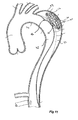
Figure 6 shows a cross-sectional view of a false lumen within the aorta. -
Figure 7 shows one embodiment of a deployment device for the intraluminal device. -
Figure 8 shows another embodiment of the deployment device of the intraluminal device. -
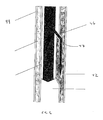
Figure 9 shows the deployment device entering a vessel and a false lumen within the aorta. -
Figure 10 shows the deployment of the intraluminal device within the false lumen shown inFigure 9 . -
Figure 11 shows the intraluminal device secured within the false lumen shown inFigure 9 . -
Figure 12 shows the intraluminal device in a compressed configuration within the false lumen shown inFigure 9 . -
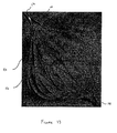
Figure 13 shows another embodiment of the intraluminal device wrapped in a membrane. - To help understand this invention, the following definitions are provided with reference to terms used in this application.
- Throughout this specification and in the appended claims, when discussing the application of this invention with respect to the aorta or other blood vessels, the term "distal" with respect to such a device, or false lumen occluder, is intended to refer to a location that is, or a portion of the device that when implanted, is further downstream with respect to blood flow; the term "distally" means in the direction of blood flow or further downstream. The term "proximal" is intended to refer to a location that is, or a portion of the device that when implanted is, further upstream with respect to blood flow; the term "proximally" means in the direction opposite to the direction of blood flow or further upstream.
- The term "intraluminal" describes objects that are found or can be placed inside a lumen in the human or animal body. A lumen can be an existing lumen or a lumen created by surgical intervention. This includes lumens such as blood vessels, such as an aorta, parts of the gastrointestinal tract, ducts such as bile ducts, parts of the respiratory system, etcetera. "Intraluminal device" is thus a device that can be placed inside one of these lumens. An expandable device having a plurality of struts is a type of intraluminal device.
- The embodiments below are described with reference to the drawings in which like elements are referred to by like numerals. The relationship and functioning of the various elements are better understood by the following detailed description. However, the embodiments as described below are by way of example only, and the invention is not limited to the embodiments illustrated in the drawings.
- This invention relates to an intraluminal device having a plurality of struts extending from a first end of the device to the second end of the device. Along at least one of the struts is a mid-strut portion having two secondary struts. The method of delivery and placement of the intraluminal device within a lumen is also part of the invention described herein.
- In the preferred embodiment, shown in
Figure 1 , anintraluminal device 10 in an expanded configuration is shown. Theintraluminal device 10 includes afirst end 12 and asecond end 14, where thefirst end 12 andsecond end 14 are along a central longitudinal axis A. A plurality ofstruts 16 extend from thefirst end 12 to thesecond end 14 and are made out of a single piece of material. Each of the plurality ofstruts 16 include aproximal portion 18 that is adjacent to thefirst end 12 and adistal portion 20 that is adjacent to thesecond end 14 of theintraluminal device 10. In this embodiment, there are 16struts 16, however the number ofstruts 16 in a particular embodiment may vary and can range anywhere between 10 and 25. - As further shown in
Figure 1 , each of the plurality ofstruts 16 further includes amid-strut portion 22. Themid-strut portion 22 is located between theproximal strut portion 18 and thedistal strut portion 20 for eachstrut 16 of the plurality of struts. In this embodiment, themid-strut portion 22 of thestrut 16 comprises twosecondary struts 24 that diverge from theproximal portion 18 of thestrut 16 and converge into thedistal portion 20 of thesame strut 16. The number ofsecondary struts 24 per eachmid-strut portion 22 can vary anywhere between two, which is shown in the embodiment disclosed inFigure 1 , up to, and including, six. Moreover, asingle strut 16 may also have more than onemid-strut portion 22, with each midstrut having two or moresecondary struts 24 extending therefrom. - The secondary struts 24 permit expansion of the
intraluminal device 10 to significantly larger diameters than would otherwise be possible with just a single strut, and also reduce the extent of foreshortening theintraluminal device 10 undergoes upon expansion. The secondary struts 24 also contribute to enhanced stiffness of theintraluminal device 10 during loading, deployment and in vivo. Further, thesecondary struts 24 increase the amount of metal in theintraluminal device 10 without contributing to the overall stiffness. - It can be appreciated that the number of
secondary struts 24 in a particular embodiment may also vary. For example, it is contemplated that in one embodiment of theintraluminal device 10, onestrut 16 may have zerosecondary struts 24, anotherstrut 16 may have twosecondary struts 24, and yet anotherstrut 16 may have foursecondary struts 24, and so forth. - The relative locations and lengths of the
mid-strut portion 22 with respect to theproximal stent portion 18 anddistal stent portion 20 may vary and is application dependent. For example, depending on the desired location ofsecondary struts 24 relative to thefirst end 12 and thesecond end 14 of theintraluminal device 10, themid-strut portion 22 may be closer to one of theends secondary struts 24 may also vary depending on the intended application. For example, in the embodiment shown inFigure 1 , themid-strut portion 22 is approximately one half the overall length of thestrut 16. This ratio may change depending on a particular application. - The
struts 16 of theintraluminal device 10 are configured to expand and compress such that thestruts 16 are substantially parallel to the longitudinal axis A when in the compressed configuration.Figure 2 depicts theintraluminal device 10 shown inFigure 1 in a compressed configuration, where thestruts 16 are substantially parallel to one another. When in the expanded configuration, theintraluminal device 10 may have a length anywhere between 10 - 80 mm and an outer diameter of anywhere between 5 - 50 mm. When in the compressed configuration, the length can vary from anywhere between 10-150 mm and have a compressed outer diameter of anywhere between about 5 -18 Fr. Theintraluminal device 10 is intended to have minimal radial force (just enough to enable deployment within the false lumen). The pattern shown in the preferred embodiment disclosed inFigure 1 lends itself to this design goal. Specifically, the pattern shown inFig 1 is laser cut from a drawn, seamless tube, expanded to its final diameter and heat-set to retain the expanded shape. The pattern consists of a series ofstruts 16 that run parallel to the long axis of theintraluminal device 10, without any circumferential interconnections. Thestruts 16 are bifurcated at approximately 1/3rd the distance from eitherend intraluminal device 10 to form a pair ofsecondary struts 24, intended to enhance stability. The lack of circumferential interconnections is intended to reduce radial force and crush resistance. - In addition, the forces required to compress the pattern into its compressed configuration (during loading) are minimized as well. In its operational state, the
intraluminal device 10 is intended to have radial and flat plate crush resistance less than a typical stent graft (e.g., less than 15 N) used for treatment of aortic aneurysms or dissections. This is essential to promote thrombosis of the false lumen and stabilization and opening of the true lumen as the blood flow increases through the lumen. - The size and shape of the
struts 16 andsecondary struts 24 may vary depending on a particular application. In the preferred embodiment shown inFigures 1 and2 , eachstrut 16 has a length of 20 mm and a width of 220 µm and each of the twosecondary struts 24 has a length of approximately 25 mm and a width of approximately 92 µm. When in the expanded configuration, each of the twosecondary struts 24 and form a 40 mm opening, or luminal diameter, 66 therebetween. - It can be appreciated that the dimensions of the
secondary struts 24 of aparticular strut 16 may depend on the number ofsecondary struts 24 for that particular embodiment. For example, if aparticular strut 16 has twosecondary struts 24, the width of each secondary strut will approximately be one half of the width of thestrut 16. And if aparticular strut 16 has threesecondary struts 24, the width of eachsecondary strut 24 will approximately be one third of the width of thestrut 16. However, this relationship between the number ofsecondary struts 24 and the width of theprimary strut 16 is not required and there also may be instances where the width of each of thesecondary struts 24 for aparticular strut 16 may be not be equal to one another. - In the embodiment shown in
Figures 1 and2 , theintraluminal device 10 is made out of a single piece of material. The types of material from which theintraluminal device 10 may be manufactured include a shape memory alloy comprised of Nickel and Titanium, which is commonly referred to as Nitinol, and Teritary alloys. As shown inFigure 3 , theintraluminal device 10 in this embodiment is manufactured out of a singlecylindrical tube 26. Thecylindrical tube 26 has a plurality ofprimary cuts 28 formed along the longitudinal axis A. Theprimary cuts 28 form thestruts 16 of theintraluminal device 10. Between eachprimary cut 28 is asecondary cut 30, which also extends along the longitudinal axis A. As shown inFigure 3 , thesecondary cuts 30 are not as long and wide as theprimary cuts 28 and form thesecondary struts 24 of theintraluminal device 10. In this embodiment, thestruts 16 and thesecondary struts 24 have a rectangular-shaped cross-section. - The dimensions of the
cuts primary cuts 28 andsecondary cuts 30 may vary in a single embodiment and the width of thecuts cut first end 12 as it approaches themid-strut portion 22 and then decrease as it approaches thesecond end 14, or vice versa, thereby affecting the shape and width of thestruts Figure 3 , the path, or pattern, along which thecuts cuts cylindrical tube 26. -
Figure 4 is theintraluminal device 10 shown inFigure 3 in the expanded configuration. As shown in this figure, when in the expanded configuration, thestruts 16 have an arcuate shape that bows away from the longitudinal axis A, and thesecondary struts 24 of eachstrut 16 bias or bend away from one another. The secondary struts 24 may bias away from each other in directions relative to the longitudinal axis, for example radially inward and outward. For example, onesecondary strut 24 may bias toward the axis and the other away from the axis. Alternatively, and preferably, thesecondary struts 24 may bias away from the longitudinal axis A and from one another in a radial direction. When in the expanded configuration, theintraluminal device 10 is ellipsoidal in shape. It is contemplated that theintraluminal device 10 may have other shapes, such as a spherical shape, depending on the geometry and pattern of thestruts intraluminal device 10 is less than when in the compressed configuration, and the maximum outside diameter of theintraluminal device 10 is greater than when in the compressed configuration. - In an alternative embodiment, shown in
Figure 5 , theintraluminal device 10 is made of a plurality ofindependent struts 32, each having afirst end 34 and asecond end 36. In this embodiment, each of the first ends 34 of theindependent struts 32 are held together via afirst hub 38 and each of the second ends 36 of theindependent struts 32 are held together via asecond hub 40. The independent struts 32 in this embodiment may also have a mid-strut portion with secondary struts that is substantially the same as themid-strut portion 22 andsecondary struts 24 described above with respect to the first embodiments. - The
intraluminal device 10 is intended to be placed intofalse lumen 42 of anaorta 44, a pictorial representation of which is shown inFigure 6 . Thefalse lumen 42 is a pocket created by a tear in the lining 46 of the aortic wall. A portion of theaortic lining 46 separates from an adjacent portion of theaortic lining 47 thereby forming a pocket. Blood flow is partially diverted into this pocket thereby creating afalse lumen 42. The pressure of the blood flow and collection of blood in thislumen 42 can cause the torn portion of theaortic lining 46 to propagate and eventually lead to the rupture of the aortic wall. - As shown in
Figure 7 , theintraluminal device 10 is loaded onto adeployment device 48 for insertion into a vessel. Thedeployment device 48 includes a guide wire catheter 50 having a first end 60 with anose cone dilator 52 attached thereto. Theintraluminal device 10 is located along abody 62 of the guide wire catheter 50 and may be radially compressed and secured thereto by twotrigger wires 58, which form loops around theintraluminal device 10. Asheath 56 is disposed over the guide wire catheter 50 andintraluminal device 10. Thesheath 56 assists thetrigger wires 58 in retaining theintraluminal device 10 in the compressed configuration prior to deployment. Note that thesheath 56 alone may be sufficient to retain theintraluminal device 10 to thebody 62 of the catheter 50. The superelastic property ofNitinol allows thestruts intraluminal device 10 to undergo considerable deformation, such as radial compression, yet return to their original shape when the compression force is removed. In the preferred embodiment, a formulation ofNitinol comprising about 49.5% to 51.5% Nickel (atomic %) and about 50.5% to 48.5% Titanium is used (atomic %). Preferably, an equiatmoic formulation of Nitinol is used. Additional formulations, consisting of ternary alloys (e.g. Nitinol doped with 0.25 at% Chromium) may be used. As a result of the superelastic property, theintraluminal device 10 may be placed in a compressed or collapsed configuration as shown inFigure 9 , yet expand back to its original configuration when deployed from thedeployment device 48 within the vessel. - In an another embodiment, the
deployment device 48, as shown inFigure 8 , includes aguide wire catheter 68 having afirst end 70 and asecond end 72 and a reduceddiameter portion 76 adjacent to thesecond end 72. Acap 74 is disposed on thesecond end 72 and forms part of theguide wire catheter 68. Thecap 74 forms acavity 78 between it and thesecond end 72 in which a portion of theintraluminal device 10 may reside in the compressed configuration. Prior to deployment, theintraluminal device 10 is positioned along the reduceddiameter portion 76 and is retained by asheath 56 and thecap 74 such that theintraluminal device 10 is retained in the compressed configuration. -
Figures 9-11 depict the deployment of theintraluminal device 10 within a blood vessel, which in this instance is theaorta 44. As shown inFigure 9 , aguide wire 54 is inserted through a femoral artery and is positioned within or adjacent to thefalse lumen 42. Alternatively, theguide wire 54 may be introduced via the subclavin artery into the aortic arch and positioned within or adjacent to thefalse lumen 42. In either scenario, thedeployment device 48 is inserted along theguide wire 54 and positioned at a point of deployment within thefalse lumen 42. Once thedeployment device 48 reaches the desired point of deployment, thesheath 56 is retracted, as shown inFigure 10 . Finally, thetrigger wires 58 securing theintraluminal device 10 to thebody 62 of theguide wire catheter 48 are disengaged from theintraluminal device 10. - As the
sheath 56 retracts, theintraluminal device 10 expands from its compressed configuration to its expanded configuration, as shown inFigure 11 . In an alternative method of deployment, thesheath 56 may be retracted before thetrigger wires 58 disengaged from theintraluminal device 10. In this scenario, the disengagement of thetrigger wires 58 from theintraluminal device 10 will cause theintraluminal device 10 to expand into its expanded configuration as shown inFigure 11 . As discussed above, the outside diameter of theintraluminal device 10 when in the expanded configuration can range between about 5-50 mm, and the exact diameter is determined by the size of thefalse lumen 42, which can vary anywhere between 5-20 mm. The radial force exerted by thestruts intraluminal device 10 ranges from 0.1 to 10 N and helps secured theintraluminal device 10 within thefalse lumen 42. - Once the
intraluminal device 10 is in the expanded configuration and secured within thefalse lumen 42, afiller material 64 may be inserted into the void formed by the expanded struts 16, 24. Examples of thefiller material 64 include: embolization coils, small intestinal submucosa (SIS), hydrogels, PETE, such as Dacron®, and microspheres. MReye® is one type of embolization coil that may be inserted into theintraluminal device 10. MReye® is used for arterial and venous embolization in the peripheral vasculature and is manufactured by Cook Medical Inc., located in Bloomington, Indiana. Thefiller material 64 may be inserted into the cavity by a second catheter or through thesame deployment device 48 that deployed theintraluminal device 10 within thefalse lumen 42. In the alternative, thefiller material 64 may be disposed within theintraluminal device 10 prior to being loaded onto thedeployment device 48. - The
filler material 64 within theintraluminal device 10 encourages the thrombotic process to occur within thefalse lumen 42. In some instances, once theintraluminal device 10 is placed within thefalse lumen 42, an endovascular stent or a stent graft may be placed in thetrue lumen 43 in order to retain the patency of thetrue lumen 43 and encourage the thrombotic process. Thrombosis will occur as a result of thefiller material 64 causing turbulence and/or stagnation in the blood flow in thefalse lumen 42. Over time, the thrombosed area will grow, with the goal being to completely occlude thefalse lumen 42 from any pressurized blood blow. The blood flow will then be restored to the normal vessel pathway. As the vessel begins to heal, it will begin to remodel and strengthen and thetrue lumen 43 will stabilize and begin to expand. The expansion of thetrue lumen 43 will cause thefalse lumen 42 to collapse. Theintraluminal device 10 has a low plate stiffness in the range of 0.1 to 10 N, which is far less than the radial force generated by the increased blood pressure exerted (or a stent graft that may be placed) within thetrue lumen 43. As a result, theintraluminal device 10 will begin to collapse as a result of the increased blood flow. Theintraluminal device 10 will eventually achieve a low profile compressed configuration, as shown inFigure 12 . - In an alternate embodiment, the
intraluminal device 10 is wrapped in amembrane 80, as shown inFigure 13 . In this embodiment, themembrane 80 is made out of a Dacron polymer fiber. The fibers are applied to thestruts 16 of theintraluminal device 10 through a method referred to as electrospinning. - The
membrane 80 prevents additional blood from entering thefalse lumen 42 and thereby decreasing the further propagation of the tear. Themembrane 80 may be made out of any suitable fiber, or material, that exhibits substantially the same properties as Dacron, including a hemostatic type of collagen or SIS. The wrapping, or covering, process occurs via electrospinning when theintraluminal device 10 is in a compressed configuration. It is desired to perform the covering process when theintraluminal device 10 is in this configuration in order to prevent the covering to split apart when theintraluminal device 10 is compressed as it is loaded onto the deployment device. Otherwise, if the covering process was performed when theintraluminal device 10 was in a non-compressed configuration, the individual layers, or strands, of themembrane 80 would not be taught and would increase the likelihood of separating from one another during the loading process. In addition, a hemispherical ground plate is used during the electrospinning process to help attract fibers to theintraluminal device 10 being coated with themembrane 80. The hemispherical ground plate provides improved control of the location the fibers of themembrane 80 are coated on theintraluminal device 10. - While the present invention has been described in terms of preferred examples, and it will be understood that the invention is not limited thereto since modifications may be made to those skilled in the art, particularly in light of the foregoing teachings.
The disclosures in United States patent application nos.61/365955 13/170843
The length of each of the at least two struts of the mid-strut portion may be approximately equal to one half of the overall length of the at least one of the plurality of struts.
The width of each of the at least two struts of the mid-strut portion may be approximately equal to one half of the width of the proximal portion of the at least one of the plurality of struts.
An intraluminal device may comprise:
Claims (15)
- An intraluminal device comprising:a first end;a second end;a plurality of struts extending from the first end to the second end; and
at least one of the plurality of struts comprising:a proximal strut portion adjacent to the first end;a distal strut portion adjacent to the second end; anda mid-strut portion between the proximal strut portion and the distal strut portion, the mid-strut portion having at least two struts;wherein when in an expanded configuration, the plurality of struts are biased away from one another and the at least two struts of the mid-strut portion are biased away from each other. - The intraluminal device of claim 1 wherein the at least two struts of the mid-strut portion have an arcuate shape when in the expanded configuration.
- The intraluminal device of any of claims 1 and 2 wherein the plurality of struts are made from a single piece of material.
- The intraluminal device of any preceding claim further comprising a fill material disposed within the device, where the fill material is selected from the group consisting of small intestinal submucosa plugs, nitinol wire, Dacron fibers, and MReye embolization coils.
- The intraluminal device of any preceding claim wherein the plurality of struts have a rectangular cross-section.
- The intraluminal device of any preceding claim wherein the at least two struts of the mid-strut portion have a rectangular cross-section.
- The intraluminal device of any preceding claim wherein when in the expanded configuration, the device has an outer diameter between about 5 mm and about 50 mm.
- The intraluminal device of any preceding claim wherein when in a compressed configuration, the device has an outer diameter between about 5 Fr to about 18 Fr.
- The intraluminal device of any preceding claim wherein the plurality of struts and the two struts of the mid strut portion are made out of the same piece of material.
- The intraluminal device of any preceding claim wherein the plurality of struts are made of at least one of the following materials: Nitinol or tertiary alloys.
- An intraluminal device comprising:a first end;a second end; anda plurality of struts extending from the first end to the second end, wherein the plurality of struts are made from the same piece of material;
wherein at least one of the plurality of struts comprises:a proximal strut portion adjacent to the first end;a distal strut portion adjacent to the second end; anda mid-strut portion between the proximal strut portion and the distal strut portion, the mid-strut portion having at least two struts;wherein when in an expanded configuration, the plurality of struts are biased away from one another and the at least two struts of the mid-strut portion have an arcuate shape. - The intraluminal device of claim 11 wherein each of the plurality of struts has a rectangular cross section.
- The intraluminal device of any of claims 11 and 12 wherein each of the plurality of struts has a mid-strut portion having at least two struts.
- The intraluminal device of any of claims 11 to 13 further comprising a fill material disposed within the device, wherein the fill material is selected from the group consisting of small intestinal submucosa plugs, nitinol wire, Dacron fibers, and MReye embolization coils.
- The intraluminal device of any of claims 11 to 14 wherein the width of each of the at least two struts of the mid-strut portion is approximately equal to one half of the width of the proximal strut portion of at least one of the plurality of struts.
Applications Claiming Priority (2)
| Application Number | Priority Date | Filing Date | Title |
|---|---|---|---|
| US36595510P | 2010-07-20 | 2010-07-20 | |
| US13/170,843 US8876849B2 (en) | 2010-07-20 | 2011-06-28 | False lumen occluder |
Publications (3)
| Publication Number | Publication Date |
|---|---|
| EP2409655A2 true EP2409655A2 (en) | 2012-01-25 |
| EP2409655A3 EP2409655A3 (en) | 2014-02-19 |
| EP2409655B1 EP2409655B1 (en) | 2017-04-05 |
Family
ID=44512658
Family Applications (1)
| Application Number | Title | Priority Date | Filing Date |
|---|---|---|---|
| EP11174324.1A Active EP2409655B1 (en) | 2010-07-20 | 2011-07-18 | False lumen occluder |
Country Status (4)
| Country | Link |
|---|---|
| US (1) | US8876849B2 (en) |
| EP (1) | EP2409655B1 (en) |
| JP (1) | JP5912317B2 (en) |
| CN (1) | CN102415909B (en) |
Cited By (3)
| Publication number | Priority date | Publication date | Assignee | Title |
|---|---|---|---|---|
| WO2012092349A1 (en) * | 2010-12-30 | 2012-07-05 | Cook Medical Technologies Llc | Self-expanding occlusion device |
| CN105125250A (en) * | 2015-09-29 | 2015-12-09 | 中国人民解放军第二军医大学 | Plug device for assisting aneurysmal neck |
| CN114010241A (en) * | 2021-11-16 | 2022-02-08 | 复旦大学附属中山医院 | Plugging device for repairing aortic dissection |
Families Citing this family (14)
| Publication number | Priority date | Publication date | Assignee | Title |
|---|---|---|---|---|
| US10772717B2 (en) | 2009-05-01 | 2020-09-15 | Endologix, Inc. | Percutaneous method and device to treat dissections |
| JP2012525239A (en) | 2009-05-01 | 2012-10-22 | エンドロジックス、インク | Transcutaneous methods and devices for treating dissociation (priority information and incorporation by reference) |
| WO2012068298A1 (en) * | 2010-11-17 | 2012-05-24 | Endologix, Inc. | Devices and methods to treat vascular dissections |
| US8911468B2 (en) * | 2011-01-31 | 2014-12-16 | Vatrix Medical, Inc. | Devices, therapeutic compositions and corresponding percutaneous treatment methods for aortic dissection |
| WO2015095538A1 (en) | 2013-12-20 | 2015-06-25 | Microvention, Inc. | Vascular occlusion |
| JP6935197B2 (en) * | 2014-03-31 | 2021-09-15 | ジャイラス エーシーエムアイ インク | Anchoring mechanisms and systems for intraluminal devices |
| US10463470B2 (en) | 2015-07-31 | 2019-11-05 | Cook Medical Technologies Llc | Methods of making a prosthesis with a smooth covering |
| US10524800B2 (en) * | 2016-05-17 | 2020-01-07 | The Cleveland Clinic Foundation | Method and apparatus for substantially blocking bloodflow through a dissected aorta |
| JP7293132B2 (en) | 2017-05-25 | 2023-06-19 | テルモ株式会社 | adhesive occlusion system |
| CN107569300A (en) * | 2017-09-25 | 2018-01-12 | 上海长海医院 | A kind of intracavitary repair implant for treating dissection of aorta vacation chamber |
| CN108113785B (en) * | 2017-12-25 | 2020-04-21 | 有研医疗器械(北京)有限公司 | Intravascular false cavity plugging support |
| WO2020093012A1 (en) | 2018-11-01 | 2020-05-07 | Terumo Corporation | Occlusion systems |
| CN115515510A (en) | 2020-04-28 | 2022-12-23 | 泰尔茂株式会社 | Plugging system |
| CN116616846A (en) * | 2023-02-21 | 2023-08-22 | 北京工业大学 | A double-layer guiding catheter with a retrievable stent |
Family Cites Families (24)
| Publication number | Priority date | Publication date | Assignee | Title |
|---|---|---|---|---|
| DK151404C (en) | 1984-05-23 | 1988-07-18 | Cook Europ Aps William | FULLY FILTER FOR IMPLANTATION IN A PATIENT'S BLOOD |
| FR2663217B1 (en) | 1990-06-15 | 1992-10-16 | Antheor | FILTERING DEVICE FOR THE PREVENTION OF EMBOLIES. |
| US5382259A (en) | 1992-10-26 | 1995-01-17 | Target Therapeutics, Inc. | Vasoocclusion coil with attached tubular woven or braided fibrous covering |
| EP0882428A3 (en) | 1997-06-05 | 2000-06-14 | Medtronic Ave, Inc. | Intravascular occlusion device |
| DE69834920T2 (en) | 1997-08-05 | 2007-05-24 | Boston Scientific Ltd., St. Michael | REMOVABLE SYSTEM FOR CLOSING AN ANEURYSMAS NECK |
| US5916235A (en) | 1997-08-13 | 1999-06-29 | The Regents Of The University Of California | Apparatus and method for the use of detachable coils in vascular aneurysms and body cavities |
| WO1999012484A1 (en) | 1997-09-05 | 1999-03-18 | Neurovasx, Inc. | Vessel occlusion device |
| US5976174A (en) | 1997-12-15 | 1999-11-02 | Ruiz; Carlos E. | Medical hole closure device and methods of use |
| US6313658B1 (en) | 1998-05-22 | 2001-11-06 | Micron Technology, Inc. | Device and method for isolating a short-circuited integrated circuit (IC) from other IC's on a semiconductor wafer |
| US6368338B1 (en) | 1999-03-05 | 2002-04-09 | Board Of Regents, The University Of Texas | Occlusion method and apparatus |
| US6428558B1 (en) | 1999-03-10 | 2002-08-06 | Cordis Corporation | Aneurysm embolization device |
| WO2000067665A1 (en) * | 1999-05-07 | 2000-11-16 | Salviac Limited | Support frame for embolic protection device |
| US20020058911A1 (en) * | 1999-05-07 | 2002-05-16 | Paul Gilson | Support frame for an embolic protection device |
| US6375668B1 (en) | 1999-06-02 | 2002-04-23 | Hanson S. Gifford | Devices and methods for treating vascular malformations |
| US6346117B1 (en) | 2000-03-02 | 2002-02-12 | Prodesco, Inc. | Bag for use in the intravascular treatment of saccular aneurysms |
| US6740331B1 (en) | 2000-08-25 | 2004-05-25 | Global Gene Therapies, Inc. | Apparatus for the delivery of drugs or gene therapy into a patient's vasculature and methods of use |
| CA2530992C (en) * | 2003-07-03 | 2012-01-03 | Cook, Inc. | Occluding device for occluding fluid flow through a body vessel |
| US7704266B2 (en) * | 2004-01-22 | 2010-04-27 | Rex Medical, L.P. | Vein filter |
| JP4531774B2 (en) * | 2004-02-04 | 2010-08-25 | カラク アーゲー | Implants for occluding passages in the body |
| US20090138035A1 (en) | 2005-09-22 | 2009-05-28 | Takaaki Isshiki | Filter for Thrombus Capture Catheter |
| DE102006013770A1 (en) * | 2006-03-24 | 2007-09-27 | Occlutech Gmbh | Occlusion instrument and method for its production |
| CN101449986B (en) * | 2007-11-28 | 2011-08-31 | 王涛 | Obturator of aorta ductus arteriosus |
| US8945170B2 (en) * | 2008-08-18 | 2015-02-03 | Cook Medical Technologies Llc | Occluding device |
| WO2011094638A1 (en) * | 2010-01-28 | 2011-08-04 | Micro Therapeutics, Inc. | Vascular remodeling device |
-
2011
- 2011-06-28 US US13/170,843 patent/US8876849B2/en active Active
- 2011-07-18 EP EP11174324.1A patent/EP2409655B1/en active Active
- 2011-07-20 CN CN201110208363.0A patent/CN102415909B/en active Active
- 2011-07-20 JP JP2011158746A patent/JP5912317B2/en active Active
Cited By (4)
| Publication number | Priority date | Publication date | Assignee | Title |
|---|---|---|---|---|
| WO2012092349A1 (en) * | 2010-12-30 | 2012-07-05 | Cook Medical Technologies Llc | Self-expanding occlusion device |
| CN105125250A (en) * | 2015-09-29 | 2015-12-09 | 中国人民解放军第二军医大学 | Plug device for assisting aneurysmal neck |
| CN114010241A (en) * | 2021-11-16 | 2022-02-08 | 复旦大学附属中山医院 | Plugging device for repairing aortic dissection |
| CN114010241B (en) * | 2021-11-16 | 2023-12-22 | 复旦大学附属中山医院 | A sealing device for aortic dissection breach repair |
Also Published As
| Publication number | Publication date |
|---|---|
| US8876849B2 (en) | 2014-11-04 |
| CN102415909B (en) | 2015-09-16 |
| JP2012030068A (en) | 2012-02-16 |
| EP2409655B1 (en) | 2017-04-05 |
| EP2409655A3 (en) | 2014-02-19 |
| CN102415909A (en) | 2012-04-18 |
| JP5912317B2 (en) | 2016-04-27 |
| US20120022573A1 (en) | 2012-01-26 |
Similar Documents
| Publication | Publication Date | Title |
|---|---|---|
| EP2409655B1 (en) | False lumen occluder | |
| US10828183B2 (en) | Low profile non-symmetrical stent | |
| AU2009215690B2 (en) | Stent/stent graft for reinforcement of vascular abnormalities and associated method | |
| US10729531B2 (en) | Low profile non-symmetrical stent | |
| EP2409670B1 (en) | Prosthesis | |
| EP0880948B1 (en) | Stent and stent-graft for treating branched vessels | |
| US7674284B2 (en) | Endoluminal graft | |
| CA2714053C (en) | Stent graft for reinforcement of vascular abnormalities and associated method | |
| US20170252146A1 (en) | Low profile non-symmetrical stent | |
| US20210015599A1 (en) | Stent graft | |
| US20120130479A1 (en) | Low profile non-symmetrical stents and stent-grafts | |
| US9486346B2 (en) | Balloon expandable stent graft and apparatus and method for expanding a balloon expandable stent graft | |
| US20230355243A1 (en) | Systems and methods for treating aneurysms | |
| EP1477134A2 (en) | Stent and stent-graft for treating branched vessels | |
| US20070150042A1 (en) | Stents with beveled ends and methods of use thereof |
Legal Events
| Date | Code | Title | Description |
|---|---|---|---|
| AK | Designated contracting states |
Kind code of ref document: A2 Designated state(s): AL AT BE BG CH CY CZ DE DK EE ES FI FR GB GR HR HU IE IS IT LI LT LU LV MC MK MT NL NO PL PT RO RS SE SI SK SM TR |
|
| AX | Request for extension of the european patent |
Extension state: BA ME |
|
| PUAI | Public reference made under article 153(3) epc to a published international application that has entered the european phase |
Free format text: ORIGINAL CODE: 0009012 |
|
| RAP1 | Party data changed (applicant data changed or rights of an application transferred) |
Owner name: COOK MEDICAL TECHNOLOGIES LLC |
|
| RIN1 | Information on inventor provided before grant (corrected) |
Inventor name: KRATZBERG, JARIN Inventor name: PURDY, JAMES D. Inventor name: CHARLEBOIS, STEVENS J Inventor name: GOPALAKRISHNAMURTHY, SHARATH Inventor name: ROEDER, BLAYNE A. |
|
| PUAL | Search report despatched |
Free format text: ORIGINAL CODE: 0009013 |
|
| AK | Designated contracting states |
Kind code of ref document: A3 Designated state(s): AL AT BE BG CH CY CZ DE DK EE ES FI FR GB GR HR HU IE IS IT LI LT LU LV MC MK MT NL NO PL PT RO RS SE SI SK SM TR |
|
| AX | Request for extension of the european patent |
Extension state: BA ME |
|
| RIC1 | Information provided on ipc code assigned before grant |
Ipc: A61B 17/12 20060101AFI20140115BHEP |
|
| 17P | Request for examination filed |
Effective date: 20140818 |
|
| RBV | Designated contracting states (corrected) |
Designated state(s): AL AT BE BG CH CY CZ DE DK EE ES FI FR GB GR HR HU IE IS IT LI LT LU LV MC MK MT NL NO PL PT RO RS SE SI SK SM TR |
|
| GRAP | Despatch of communication of intention to grant a patent |
Free format text: ORIGINAL CODE: EPIDOSNIGR1 |
|
| INTG | Intention to grant announced |
Effective date: 20161025 |
|
| RIN1 | Information on inventor provided before grant (corrected) |
Inventor name: KRATZBERG, JARIN Inventor name: PURDY, JAMES D. Inventor name: GOPALAKRISHNAMURTHY, SHARATH Inventor name: ROEDER, BLAYNE A. Inventor name: CHARLEBOIS, STEVEN J |
|
| STAA | Information on the status of an ep patent application or granted ep patent |
Free format text: STATUS: GRANT OF PATENT IS INTENDED |
|
| GRAS | Grant fee paid |
Free format text: ORIGINAL CODE: EPIDOSNIGR3 |
|
| GRAA | (expected) grant |
Free format text: ORIGINAL CODE: 0009210 |
|
| STAA | Information on the status of an ep patent application or granted ep patent |
Free format text: STATUS: THE PATENT HAS BEEN GRANTED |
|
| AK | Designated contracting states |
Kind code of ref document: B1 Designated state(s): AL AT BE BG CH CY CZ DE DK EE ES FI FR GB GR HR HU IE IS IT LI LT LU LV MC MK MT NL NO PL PT RO RS SE SI SK SM TR |
|
| REG | Reference to a national code |
Ref country code: GB Ref legal event code: FG4D |
|
| REG | Reference to a national code |
Ref country code: CH Ref legal event code: EP |
|
| REG | Reference to a national code |
Ref country code: AT Ref legal event code: REF Ref document number: 881032 Country of ref document: AT Kind code of ref document: T Effective date: 20170415 |
|
| REG | Reference to a national code |
Ref country code: IE Ref legal event code: FG4D |
|
| REG | Reference to a national code |
Ref country code: DE Ref legal event code: R096 Ref document number: 602011036596 Country of ref document: DE |
|
| REG | Reference to a national code |
Ref country code: NL Ref legal event code: MP Effective date: 20170405 |
|
| REG | Reference to a national code |
Ref country code: LT Ref legal event code: MG4D |
|
| REG | Reference to a national code |
Ref country code: AT Ref legal event code: MK05 Ref document number: 881032 Country of ref document: AT Kind code of ref document: T Effective date: 20170405 |
|
| PG25 | Lapsed in a contracting state [announced via postgrant information from national office to epo] |
Ref country code: NL Free format text: LAPSE BECAUSE OF FAILURE TO SUBMIT A TRANSLATION OF THE DESCRIPTION OR TO PAY THE FEE WITHIN THE PRESCRIBED TIME-LIMIT Effective date: 20170405 |
|
| PG25 | Lapsed in a contracting state [announced via postgrant information from national office to epo] |
Ref country code: HR Free format text: LAPSE BECAUSE OF FAILURE TO SUBMIT A TRANSLATION OF THE DESCRIPTION OR TO PAY THE FEE WITHIN THE PRESCRIBED TIME-LIMIT Effective date: 20170405 Ref country code: NO Free format text: LAPSE BECAUSE OF FAILURE TO SUBMIT A TRANSLATION OF THE DESCRIPTION OR TO PAY THE FEE WITHIN THE PRESCRIBED TIME-LIMIT Effective date: 20170705 Ref country code: ES Free format text: LAPSE BECAUSE OF FAILURE TO SUBMIT A TRANSLATION OF THE DESCRIPTION OR TO PAY THE FEE WITHIN THE PRESCRIBED TIME-LIMIT Effective date: 20170405 Ref country code: FI Free format text: LAPSE BECAUSE OF FAILURE TO SUBMIT A TRANSLATION OF THE DESCRIPTION OR TO PAY THE FEE WITHIN THE PRESCRIBED TIME-LIMIT Effective date: 20170405 Ref country code: LT Free format text: LAPSE BECAUSE OF FAILURE TO SUBMIT A TRANSLATION OF THE DESCRIPTION OR TO PAY THE FEE WITHIN THE PRESCRIBED TIME-LIMIT Effective date: 20170405 Ref country code: GR Free format text: LAPSE BECAUSE OF FAILURE TO SUBMIT A TRANSLATION OF THE DESCRIPTION OR TO PAY THE FEE WITHIN THE PRESCRIBED TIME-LIMIT Effective date: 20170706 Ref country code: AT Free format text: LAPSE BECAUSE OF FAILURE TO SUBMIT A TRANSLATION OF THE DESCRIPTION OR TO PAY THE FEE WITHIN THE PRESCRIBED TIME-LIMIT Effective date: 20170405 |
|
| PG25 | Lapsed in a contracting state [announced via postgrant information from national office to epo] |
Ref country code: IS Free format text: LAPSE BECAUSE OF FAILURE TO SUBMIT A TRANSLATION OF THE DESCRIPTION OR TO PAY THE FEE WITHIN THE PRESCRIBED TIME-LIMIT Effective date: 20170805 Ref country code: BG Free format text: LAPSE BECAUSE OF FAILURE TO SUBMIT A TRANSLATION OF THE DESCRIPTION OR TO PAY THE FEE WITHIN THE PRESCRIBED TIME-LIMIT Effective date: 20170705 Ref country code: LV Free format text: LAPSE BECAUSE OF FAILURE TO SUBMIT A TRANSLATION OF THE DESCRIPTION OR TO PAY THE FEE WITHIN THE PRESCRIBED TIME-LIMIT Effective date: 20170405 Ref country code: SE Free format text: LAPSE BECAUSE OF FAILURE TO SUBMIT A TRANSLATION OF THE DESCRIPTION OR TO PAY THE FEE WITHIN THE PRESCRIBED TIME-LIMIT Effective date: 20170405 Ref country code: RS Free format text: LAPSE BECAUSE OF FAILURE TO SUBMIT A TRANSLATION OF THE DESCRIPTION OR TO PAY THE FEE WITHIN THE PRESCRIBED TIME-LIMIT Effective date: 20170405 Ref country code: PL Free format text: LAPSE BECAUSE OF FAILURE TO SUBMIT A TRANSLATION OF THE DESCRIPTION OR TO PAY THE FEE WITHIN THE PRESCRIBED TIME-LIMIT Effective date: 20170405 |
|
| REG | Reference to a national code |
Ref country code: DE Ref legal event code: R097 Ref document number: 602011036596 Country of ref document: DE |
|
| PG25 | Lapsed in a contracting state [announced via postgrant information from national office to epo] |
Ref country code: SK Free format text: LAPSE BECAUSE OF FAILURE TO SUBMIT A TRANSLATION OF THE DESCRIPTION OR TO PAY THE FEE WITHIN THE PRESCRIBED TIME-LIMIT Effective date: 20170405 Ref country code: EE Free format text: LAPSE BECAUSE OF FAILURE TO SUBMIT A TRANSLATION OF THE DESCRIPTION OR TO PAY THE FEE WITHIN THE PRESCRIBED TIME-LIMIT Effective date: 20170405 Ref country code: DK Free format text: LAPSE BECAUSE OF FAILURE TO SUBMIT A TRANSLATION OF THE DESCRIPTION OR TO PAY THE FEE WITHIN THE PRESCRIBED TIME-LIMIT Effective date: 20170405 Ref country code: CZ Free format text: LAPSE BECAUSE OF FAILURE TO SUBMIT A TRANSLATION OF THE DESCRIPTION OR TO PAY THE FEE WITHIN THE PRESCRIBED TIME-LIMIT Effective date: 20170405 Ref country code: RO Free format text: LAPSE BECAUSE OF FAILURE TO SUBMIT A TRANSLATION OF THE DESCRIPTION OR TO PAY THE FEE WITHIN THE PRESCRIBED TIME-LIMIT Effective date: 20170405 |
|
| PLBE | No opposition filed within time limit |
Free format text: ORIGINAL CODE: 0009261 |
|
| STAA | Information on the status of an ep patent application or granted ep patent |
Free format text: STATUS: NO OPPOSITION FILED WITHIN TIME LIMIT |
|
| PG25 | Lapsed in a contracting state [announced via postgrant information from national office to epo] |
Ref country code: IT Free format text: LAPSE BECAUSE OF FAILURE TO SUBMIT A TRANSLATION OF THE DESCRIPTION OR TO PAY THE FEE WITHIN THE PRESCRIBED TIME-LIMIT Effective date: 20170405 Ref country code: SM Free format text: LAPSE BECAUSE OF FAILURE TO SUBMIT A TRANSLATION OF THE DESCRIPTION OR TO PAY THE FEE WITHIN THE PRESCRIBED TIME-LIMIT Effective date: 20170405 |
|
| REG | Reference to a national code |
Ref country code: CH Ref legal event code: PL |
|
| 26N | No opposition filed |
Effective date: 20180108 |
|
| REG | Reference to a national code |
Ref country code: FR Ref legal event code: ST Effective date: 20180330 |
|
| PG25 | Lapsed in a contracting state [announced via postgrant information from national office to epo] |
Ref country code: LI Free format text: LAPSE BECAUSE OF NON-PAYMENT OF DUE FEES Effective date: 20170731 Ref country code: CH Free format text: LAPSE BECAUSE OF NON-PAYMENT OF DUE FEES Effective date: 20170731 |
|
| PG25 | Lapsed in a contracting state [announced via postgrant information from national office to epo] |
Ref country code: SI Free format text: LAPSE BECAUSE OF FAILURE TO SUBMIT A TRANSLATION OF THE DESCRIPTION OR TO PAY THE FEE WITHIN THE PRESCRIBED TIME-LIMIT Effective date: 20170405 Ref country code: FR Free format text: LAPSE BECAUSE OF NON-PAYMENT OF DUE FEES Effective date: 20170731 |
|
| REG | Reference to a national code |
Ref country code: BE Ref legal event code: MM Effective date: 20170731 |
|
| PG25 | Lapsed in a contracting state [announced via postgrant information from national office to epo] |
Ref country code: LU Free format text: LAPSE BECAUSE OF NON-PAYMENT OF DUE FEES Effective date: 20170718 |
|
| PG25 | Lapsed in a contracting state [announced via postgrant information from national office to epo] |
Ref country code: BE Free format text: LAPSE BECAUSE OF NON-PAYMENT OF DUE FEES Effective date: 20170731 |
|
| PG25 | Lapsed in a contracting state [announced via postgrant information from national office to epo] |
Ref country code: MT Free format text: LAPSE BECAUSE OF NON-PAYMENT OF DUE FEES Effective date: 20170718 |
|
| PG25 | Lapsed in a contracting state [announced via postgrant information from national office to epo] |
Ref country code: MC Free format text: LAPSE BECAUSE OF FAILURE TO SUBMIT A TRANSLATION OF THE DESCRIPTION OR TO PAY THE FEE WITHIN THE PRESCRIBED TIME-LIMIT Effective date: 20170405 Ref country code: HU Free format text: LAPSE BECAUSE OF FAILURE TO SUBMIT A TRANSLATION OF THE DESCRIPTION OR TO PAY THE FEE WITHIN THE PRESCRIBED TIME-LIMIT; INVALID AB INITIO Effective date: 20110718 |
|
| PG25 | Lapsed in a contracting state [announced via postgrant information from national office to epo] |
Ref country code: CY Free format text: LAPSE BECAUSE OF NON-PAYMENT OF DUE FEES Effective date: 20170405 |
|
| PG25 | Lapsed in a contracting state [announced via postgrant information from national office to epo] |
Ref country code: MK Free format text: LAPSE BECAUSE OF FAILURE TO SUBMIT A TRANSLATION OF THE DESCRIPTION OR TO PAY THE FEE WITHIN THE PRESCRIBED TIME-LIMIT Effective date: 20170405 |
|
| PG25 | Lapsed in a contracting state [announced via postgrant information from national office to epo] |
Ref country code: TR Free format text: LAPSE BECAUSE OF FAILURE TO SUBMIT A TRANSLATION OF THE DESCRIPTION OR TO PAY THE FEE WITHIN THE PRESCRIBED TIME-LIMIT Effective date: 20170405 |
|
| PG25 | Lapsed in a contracting state [announced via postgrant information from national office to epo] |
Ref country code: PT Free format text: LAPSE BECAUSE OF FAILURE TO SUBMIT A TRANSLATION OF THE DESCRIPTION OR TO PAY THE FEE WITHIN THE PRESCRIBED TIME-LIMIT Effective date: 20170405 |
|
| PG25 | Lapsed in a contracting state [announced via postgrant information from national office to epo] |
Ref country code: AL Free format text: LAPSE BECAUSE OF FAILURE TO SUBMIT A TRANSLATION OF THE DESCRIPTION OR TO PAY THE FEE WITHIN THE PRESCRIBED TIME-LIMIT Effective date: 20170405 |
|
| P01 | Opt-out of the competence of the unified patent court (upc) registered |
Effective date: 20230602 |
|
| PGFP | Annual fee paid to national office [announced via postgrant information from national office to epo] |
Ref country code: DE Payment date: 20250728 Year of fee payment: 15 |
|
| PGFP | Annual fee paid to national office [announced via postgrant information from national office to epo] |
Ref country code: GB Payment date: 20250722 Year of fee payment: 15 |
|
| PGFP | Annual fee paid to national office [announced via postgrant information from national office to epo] |
Ref country code: IE Payment date: 20250718 Year of fee payment: 15 |