EP2409649A1 - Ultrasonic diagnostic apparatus and method thereof - Google Patents
Ultrasonic diagnostic apparatus and method thereof Download PDFInfo
- Publication number
- EP2409649A1 EP2409649A1 EP20110163289 EP11163289A EP2409649A1 EP 2409649 A1 EP2409649 A1 EP 2409649A1 EP 20110163289 EP20110163289 EP 20110163289 EP 11163289 A EP11163289 A EP 11163289A EP 2409649 A1 EP2409649 A1 EP 2409649A1
- Authority
- EP
- European Patent Office
- Prior art keywords
- measurement data
- image
- display unit
- region
- user
- Prior art date
- Legal status (The legal status is an assumption and is not a legal conclusion. Google has not performed a legal analysis and makes no representation as to the accuracy of the status listed.)
- Granted
Links
Images

Classifications
-
- A—HUMAN NECESSITIES
- A61—MEDICAL OR VETERINARY SCIENCE; HYGIENE
- A61B—DIAGNOSIS; SURGERY; IDENTIFICATION
- A61B8/00—Diagnosis using ultrasonic, sonic or infrasonic waves
- A61B8/06—Measuring blood flow
-
- A—HUMAN NECESSITIES
- A61—MEDICAL OR VETERINARY SCIENCE; HYGIENE
- A61B—DIAGNOSIS; SURGERY; IDENTIFICATION
- A61B8/00—Diagnosis using ultrasonic, sonic or infrasonic waves
- A61B8/46—Ultrasonic, sonic or infrasonic diagnostic devices with special arrangements for interfacing with the operator or the patient
- A61B8/461—Displaying means of special interest
- A61B8/463—Displaying means of special interest characterised by displaying multiple images or images and diagnostic data on one display
-
- G—PHYSICS
- G01—MEASURING; TESTING
- G01S—RADIO DIRECTION-FINDING; RADIO NAVIGATION; DETERMINING DISTANCE OR VELOCITY BY USE OF RADIO WAVES; LOCATING OR PRESENCE-DETECTING BY USE OF THE REFLECTION OR RERADIATION OF RADIO WAVES; ANALOGOUS ARRANGEMENTS USING OTHER WAVES
- G01S7/00—Details of systems according to groups G01S13/00, G01S15/00, G01S17/00
- G01S7/52—Details of systems according to groups G01S13/00, G01S15/00, G01S17/00 of systems according to group G01S15/00
- G01S7/52017—Details of systems according to groups G01S13/00, G01S15/00, G01S17/00 of systems according to group G01S15/00 particularly adapted to short-range imaging
- G01S7/52053—Display arrangements
- G01S7/52057—Cathode ray tube displays
- G01S7/5206—Two-dimensional coordinated display of distance and direction; B-scan display
- G01S7/52066—Time-position or time-motion displays
-
- G—PHYSICS
- G01—MEASURING; TESTING
- G01S—RADIO DIRECTION-FINDING; RADIO NAVIGATION; DETERMINING DISTANCE OR VELOCITY BY USE OF RADIO WAVES; LOCATING OR PRESENCE-DETECTING BY USE OF THE REFLECTION OR RERADIATION OF RADIO WAVES; ANALOGOUS ARRANGEMENTS USING OTHER WAVES
- G01S7/00—Details of systems according to groups G01S13/00, G01S15/00, G01S17/00
- G01S7/52—Details of systems according to groups G01S13/00, G01S15/00, G01S17/00 of systems according to group G01S15/00
- G01S7/52017—Details of systems according to groups G01S13/00, G01S15/00, G01S17/00 of systems according to group G01S15/00 particularly adapted to short-range imaging
- G01S7/52053—Display arrangements
- G01S7/52057—Cathode ray tube displays
- G01S7/52074—Composite displays, e.g. split-screen displays; Combination of multiple images or of images and alphanumeric tabular information
-
- A—HUMAN NECESSITIES
- A61—MEDICAL OR VETERINARY SCIENCE; HYGIENE
- A61B—DIAGNOSIS; SURGERY; IDENTIFICATION
- A61B8/00—Diagnosis using ultrasonic, sonic or infrasonic waves
- A61B8/46—Ultrasonic, sonic or infrasonic diagnostic devices with special arrangements for interfacing with the operator or the patient
- A61B8/467—Ultrasonic, sonic or infrasonic diagnostic devices with special arrangements for interfacing with the operator or the patient characterised by special input means
-
- G—PHYSICS
- G01—MEASURING; TESTING
- G01S—RADIO DIRECTION-FINDING; RADIO NAVIGATION; DETERMINING DISTANCE OR VELOCITY BY USE OF RADIO WAVES; LOCATING OR PRESENCE-DETECTING BY USE OF THE REFLECTION OR RERADIATION OF RADIO WAVES; ANALOGOUS ARRANGEMENTS USING OTHER WAVES
- G01S7/00—Details of systems according to groups G01S13/00, G01S15/00, G01S17/00
- G01S7/52—Details of systems according to groups G01S13/00, G01S15/00, G01S17/00 of systems according to group G01S15/00
- G01S7/52017—Details of systems according to groups G01S13/00, G01S15/00, G01S17/00 of systems according to group G01S15/00 particularly adapted to short-range imaging
- G01S7/52053—Display arrangements
- G01S7/52057—Cathode ray tube displays
- G01S7/52073—Production of cursor lines, markers or indicia by electronic means
Definitions
- the present disclosure relates to an ultrasonic diagnostic apparatus and a diagnosis method thereof. Particularly, upon ultrasonic diagnosis of an object, the present invention allows a user to easily locate a desired time point and section among the whole information regarding ultrasound images and a variety of measurement data which are obtained over extended use of the ultrasonic diagnosis apparatus.
- Ultrasonic diagnostic apparatuses are used in a wide range of applications.
- ultrasonic diagnostic apparatuses are used in a wide range of medical applications due to non-invasive and non-destructive characteristics thereof.
- high performance ultrasonic diagnostic apparatuses have been used to provide two-dimensional or three-dimensional images of internal organs.
- a probe of the ultrasonic diagnostic apparatus includes a transducer for transmitting and receiving wideband ultrasound signals.
- a transducer for transmitting and receiving wideband ultrasound signals.
- an ultrasound signal is generated by the transducer and delivered to an object.
- An ultrasound wave echo signal which is reflected from the object to the transducer, is transformed into an electrical signal. Then, the transformed electrical signal is amplified and processed to provide ultrasound image data.
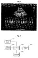
- Fig. 1 is a view explaining an image display method of a display unit of a conventional ultrasonic diagnostic apparatus.
- a B-mode (brightness mode) image which displays magnitude of ultrasound echo signals reflected from an object with brightness is displayed for example on an upper side of a screen.
- Measuring information or biological information such as a blood flow rate at a location that corresponds to a section (dotted line) specified by a user in the B-mode image, is displayed on a lower side below the B-mode image. Accordingly, the measuring information for the corresponding specified section can be displayed with time.
- a range bar is also provided at the lower side of the screen in Fig. 1 to indicate to which section in the whole diagnosis period the current time point belongs. Accordingly, through the range bar, a user can recognize the section in the whole diagnosis period, to which the currently displayed image belongs.
- a user can only recognize the section in the whole diagnosis period by observing the range bar displayed on the display screen, but in fact, the user cannot easily check a section of interest (e.g., a section in which blood flow rate excessively increases). That is, since the display screen displays only an image at a current time point or an image near a time point selected in the range bar, a user cannot easily check or identify a section in which abnormal event has occurred. Thus, in order to check such a section, the user must slowly examine the whole period in detail using a track ball or the like provided to the apparatus so as to reach the section of interest.
- a track ball or the like provided to the apparatus so as to reach the section of interest.
- the present disclosure provides an ultrasonic diagnostic apparatus and a diagnosis method thereof, which allow a user to easily locate a desired time point and section among the whole information regarding ultrasound images and a variety of measurement data which are obtained over extended use of the ultrasonic diagnosis apparatus.
- an ultrasonic diagnostic apparatus displaying an ultrasound image obtained from an object on a first region of a display unit, and displaying image information regarding measurement data with respect to a desired section of the ultrasound image on a second region of the display unit, wherein the image information displayed on the second region includes an image map in which overall measurement data obtained at respective diagnosis points are accumulated in a time-series manner.
- the apparatus may allow a user to search the measurement data and select a desired time point using the image map, and detailed measurement data at the selected time point may be displayed on a third region of the display unit.
- Image magnification of the image map may be automatically controlled with respect to a time period of data accumulation according to a total amount of the accumulated measurement data.
- the measurement data may include blood flow rate.
- the apparatus may include: a signal acquisition unit configured to receive an ultrasound signal reflected from an object; the display unit; an input unit; a storage; and a controller configured to control the apparatus to create an ultrasound image using the ultrasound signal, to provide the ultrasound image and image information to the display unit, to display detailed measurement data corresponding to a time point in the image map selected through the input unit by a user on the third region of the display unit, and to store all or part of the measurement data in the storage.
- the apparatus may allow a user to search the measurement data and select a desired time point using the image map, and the measurement data corresponding to the selected time section may be stored in the storage.
- a diagnosis method of an ultrasonic diagnostic apparatus which displays an ultrasound image obtained from an object on a first region of a display unit, comprises: obtaining measurement data that corresponds to a specified section of the ultrasound image selected by a user and displaying, on a second region of the display unit, an image map in which the obtained measurement data are accumulated in a time-series manner; receiving a desired time point in the image map selected by a user; and displaying, on a third region of the display unit, measurement data corresponding to the selected time point.
- the method may further include: receiving a desired time section selected through the image map by a user; and storing the measurement data corresponding to the selected time section in a storage.
- Fig. 1 is a view explaining an image display method of a display unit of a conventional ultrasonic diagnostic apparatus
- Fig. 2 is a view of an ultrasonic diagnostic apparatus according to an exemplary embodiment of the present disclosure
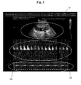
- Fig. 3 is a view explaining an image display method of a display unit of the ultrasonic diagnostic apparatus of the embodiment of the present disclosure.
- Fig. 4 is a view explaining variation in image magnification with respect to time period in an image map of the apparatus according to the embodiment of the present disclosure.
- Fig. 2 is a view of an ultrasonic diagnostic apparatus according to an exemplary embodiment of the present disclosure.
- the ultrasonic diagnostic apparatus of this embodiment includes an input unit 100; a signal acquisition unit 200 receiving an ultrasound signal reflected from an object; a display unit 400; a storage 500; and a controller 300.
- the controller 300 controls the apparatus to create an ultrasound image using the ultrasound signal, to provide the ultrasound image and image information regarding measurement data to the display unit 400, to display detailed measurement data, which corresponds to a time point in an image map selected through the input unit 100 by a user, on a third region 30 (see Fig. 3 ) of the display unit 400, and to store all or part of the measurement data in the storage 500.
- the signal acquisition unit 200 transmits an ultrasound signal to an object and receives the ultrasound signal reflected from the object to create an ultrasound image.
- the controller 300 creates the ultrasound image using the ultrasound signal sent from the signal acquisition unit, and provides the ultrasound image to the display unit 400.
- the controller 300 allows the ultrasound image to be displayed in a B-mode (brightness-mode) on a first region 10 at an upper side of a screen of the display unit 400.
- B-mode means a diagnostic mode in which the magnitude of an ultrasound echo signal reflected from the object is displayed based upon brightness on the screen. It should be understood that the ultrasound image can be displayed on the screen in a variety of other modes according to embodiments.
- the controller 300 creates image information regarding measurement data that corresponds to a specified section (dotted line section of reference numeral 10 in Fig. 3 ) of the ultrasound image selected through the input unit 100 by a user, and provides the image information to the display unit 400.
- the controller 300 allows the image information to be displayed in a PW-mode (pulse wave mode) on a second region 20 at a lower side of the screen of the display unit 400.
- the PW-mode means a diagnostic mode in which a blood flow rate with respect to a predetermined specified section of the object is displayed as a graphical image of time-blood flow rate.
- the input unit 100 all of available user interfaces may be employed, and particularly the input unit may also be formed in a touch-screen form.
- the present embodiment is different from the conventional case. That is, since the conventional PW-mode illustrates information on the blood flow rate at the respective diagnosis points as an image pattern that changes over time, as shown in the middle of Fig. 1 or in the third region 30 of Fig. 3 , the information on the blood flow rate at time points that have passed cannot be displayed, when a certain period of time (few seconds to tens of seconds) elapses.
- the image information displayed on the second region 20 includes an image map which accumulates all information regarding the blood flow rate, i.e. all time-series measurement data, obtained at the respective diagnosis points.
- the information regarding the blood flow rate can be easily and effectively checked even after the diagnosis point has considerably elapsed. Thereby a user can recognize a time point when an abnormal event such as an excessive increase in blood flow rate has occurred.
- the controller 300 in order to allow the blood flow rate information with respect to an entire diagnosis time period to be included in the image map displayed on the second region 20, the controller 300 enables an image magnification of the measurement data with respect to a diagnosis time period (time period of data accumulation) to be automatically regulated based on the total amount of measurement data (blood flow rate information) accumulated over time when forming the image map. Namely, if only a short period of time, for example 10 seconds, passes after starting diagnosis, the image is allowed to be displayed in a relatively large scale as shown in the first figure of Fig. 4 , and, as the time continuously passes, the image magnification of the measurement data with respect to the time period is automatically regulated such that it gradually decreases.
- a diagnosis time period time period of data accumulation
- the controller 300 allows a PW-mode image with respect to information regarding a blood flow rate at a time point of an abnormal event to be displayed on the third region 30.
- the controller 300 allows detailed measurement data (i.e. blood flow rate information) at the selected point to be displayed on the third region 30 in the middle of the display unit 400.
- the image displayed on the third region 30 corresponds to a section defined by brackets [ ] of the second region 20 of Fig. 3 .
- it may be configured such that a predetermined section after and before a time point selected by a user is displayed as an image on the third region, or otherwise it may be configured to allow a user to directly set a start point and an end point of a section.
- the controller 300 may allow all or a portion of measurement data such as blood flow rate information or the like to be stored in the storage 500. Particularly, when a user selects a specified time section using the image map, the controller 300 may allow the measurement data, such as blood flow rate information, and/or an ultrasound image, which correspond to the selected time section, to be stored in the storage 500.
- an image map may be displayed in a M-mode (motion-mode) or in a CW-mode (continuous wave mode), which shows motion of an object in a periodic manner, and other diverse modes are also applicable.
- M-mode motion-mode
- CW-mode continuous wave mode
- the controller can be divided into a signal processor for processing signals and a control unit serving as a processor in certain embodiments, it should be understood that the controller according to the present embodiment encompasses such a modification of the controller.
- the storage 500 of the present embodiment means all kinds of memories or storage media generally including a volatile memory, a non-volatile memory, an internal memory, an external memory, and the like.
- the apparatus allows a user to effectively locate and determine a section of interest, such as a section where an abnormal event (e.g., an excessive increase in blood flow rate) has occurred, using an image map which accumulates measurement data obtained during diagnosis. Further, when the section of interest in the image map is selected by a user, the apparatus allows the user to check corresponding detailed measurement data. Furthermore, the apparatus allows required or useful information to be stored and effectively utilized in the future.
- an abnormal event e.g., an excessive increase in blood flow rate
- a user can easily locate a desired time point and section among the whole information regarding ultrasound images and a variety of measurement data which are obtained over extended use of the ultrasonic diagnosis apparatus, and data corresponding to the desired section selected by the user can be stored for future use.
Landscapes
- Health & Medical Sciences (AREA)
- Engineering & Computer Science (AREA)
- Life Sciences & Earth Sciences (AREA)
- Physics & Mathematics (AREA)
- Heart & Thoracic Surgery (AREA)
- Surgery (AREA)
- Pathology (AREA)
- Radiology & Medical Imaging (AREA)
- Biophysics (AREA)
- Biomedical Technology (AREA)
- Remote Sensing (AREA)
- Medical Informatics (AREA)
- Molecular Biology (AREA)
- Nuclear Medicine, Radiotherapy & Molecular Imaging (AREA)
- Animal Behavior & Ethology (AREA)
- General Health & Medical Sciences (AREA)
- Public Health (AREA)
- Veterinary Medicine (AREA)
- Computer Networks & Wireless Communication (AREA)
- General Physics & Mathematics (AREA)
- Radar, Positioning & Navigation (AREA)
- Hematology (AREA)
- Ultra Sonic Daignosis Equipment (AREA)
Abstract
Description
- The present disclosure relates to an ultrasonic diagnostic apparatus and a diagnosis method thereof. Particularly, upon ultrasonic diagnosis of an object, the present invention allows a user to easily locate a desired time point and section among the whole information regarding ultrasound images and a variety of measurement data which are obtained over extended use of the ultrasonic diagnosis apparatus.
- Ultrasonic diagnostic apparatuses are used in a wide range of applications. For example, ultrasonic diagnostic apparatuses are used in a wide range of medical applications due to non-invasive and non-destructive characteristics thereof. Recently, high performance ultrasonic diagnostic apparatuses have been used to provide two-dimensional or three-dimensional images of internal organs.
- Generally, a probe of the ultrasonic diagnostic apparatus includes a transducer for transmitting and receiving wideband ultrasound signals. When the transducer is electrically driven, an ultrasound signal is generated by the transducer and delivered to an object. An ultrasound wave echo signal, which is reflected from the object to the transducer, is transformed into an electrical signal. Then, the transformed electrical signal is amplified and processed to provide ultrasound image data.
-
Fig. 1 is a view explaining an image display method of a display unit of a conventional ultrasonic diagnostic apparatus. In the related art, as shown inFig. 1 , a B-mode (brightness mode) image which displays magnitude of ultrasound echo signals reflected from an object with brightness is displayed for example on an upper side of a screen. Measuring information or biological information, such as a blood flow rate at a location that corresponds to a section (dotted line) specified by a user in the B-mode image, is displayed on a lower side below the B-mode image. Accordingly, the measuring information for the corresponding specified section can be displayed with time. - In addition, in the conventional ultrasonic diagnostic apparatus, a range bar is also provided at the lower side of the screen in
Fig. 1 to indicate to which section in the whole diagnosis period the current time point belongs. Accordingly, through the range bar, a user can recognize the section in the whole diagnosis period, to which the currently displayed image belongs. - However, according to the conventional ultrasonic diagnostic apparatus, a user can only recognize the section in the whole diagnosis period by observing the range bar displayed on the display screen, but in fact, the user cannot easily check a section of interest (e.g., a section in which blood flow rate excessively increases). That is, since the display screen displays only an image at a current time point or an image near a time point selected in the range bar, a user cannot easily check or identify a section in which abnormal event has occurred. Thus, in order to check such a section, the user must slowly examine the whole period in detail using a track ball or the like provided to the apparatus so as to reach the section of interest.
- To improve the art and address the above, the present disclosure provides an ultrasonic diagnostic apparatus and a diagnosis method thereof, which allow a user to easily locate a desired time point and section among the whole information regarding ultrasound images and a variety of measurement data which are obtained over extended use of the ultrasonic diagnosis apparatus.
- In accordance with one aspect, an ultrasonic diagnostic apparatus: displaying an ultrasound image obtained from an object on a first region of a display unit, and displaying image information regarding measurement data with respect to a desired section of the ultrasound image on a second region of the display unit, wherein the image information displayed on the second region includes an image map in which overall measurement data obtained at respective diagnosis points are accumulated in a time-series manner.
- The apparatus may allow a user to search the measurement data and select a desired time point using the image map, and detailed measurement data at the selected time point may be displayed on a third region of the display unit.
- Image magnification of the image map may be automatically controlled with respect to a time period of data accumulation according to a total amount of the accumulated measurement data.
- The measurement data may include blood flow rate.
- The apparatus may include: a signal acquisition unit configured to receive an ultrasound signal reflected from an object; the display unit; an input unit; a storage; and a controller configured to control the apparatus to create an ultrasound image using the ultrasound signal, to provide the ultrasound image and image information to the display unit, to display detailed measurement data corresponding to a time point in the image map selected through the input unit by a user on the third region of the display unit, and to store all or part of the measurement data in the storage.
- The apparatus may allow a user to search the measurement data and select a desired time point using the image map, and the measurement data corresponding to the selected time section may be stored in the storage.
- In accordance with another aspect, a diagnosis method of an ultrasonic diagnostic apparatus which displays an ultrasound image obtained from an object on a first region of a display unit, comprises: obtaining measurement data that corresponds to a specified section of the ultrasound image selected by a user and displaying, on a second region of the display unit, an image map in which the obtained measurement data are accumulated in a time-series manner; receiving a desired time point in the image map selected by a user; and displaying, on a third region of the display unit, measurement data corresponding to the selected time point.
- The method may further include: receiving a desired time section selected through the image map by a user; and storing the measurement data corresponding to the selected time section in a storage.
- The figures depict one or more implementations in accordance with the present disclosure, by way of example only, not by way of limitation. In the figures, like reference numerals refer to the same or similar elements.
-
Fig. 1 is a view explaining an image display method of a display unit of a conventional ultrasonic diagnostic apparatus; -
Fig. 2 is a view of an ultrasonic diagnostic apparatus according to an exemplary embodiment of the present disclosure; -
Fig. 3 is a view explaining an image display method of a display unit of the ultrasonic diagnostic apparatus of the embodiment of the present disclosure; and -
Fig. 4 is a view explaining variation in image magnification with respect to time period in an image map of the apparatus according to the embodiment of the present disclosure. - Exemplary embodiments of the present disclosure will now be described in detail with reference to the accompanying drawings. It should be noted that the drawings are not to precise scale and may be exaggerated in thickness of lines or size of components for descriptive convenience and clarity only. Furthermore, terms used herein are defined by taking functions of the present disclosure into account and can be changed according to the custom or intention of users or operators. Therefore, the terms should be defined according to the overall disclosures set forth herein.
-
Fig. 2 is a view of an ultrasonic diagnostic apparatus according to an exemplary embodiment of the present disclosure. - Referring to
Fig. 2 , the ultrasonic diagnostic apparatus of this embodiment includes aninput unit 100; asignal acquisition unit 200 receiving an ultrasound signal reflected from an object; adisplay unit 400; astorage 500; and acontroller 300. Thecontroller 300 controls the apparatus to create an ultrasound image using the ultrasound signal, to provide the ultrasound image and image information regarding measurement data to thedisplay unit 400, to display detailed measurement data, which corresponds to a time point in an image map selected through theinput unit 100 by a user, on a third region 30 (seeFig. 3 ) of thedisplay unit 400, and to store all or part of the measurement data in thestorage 500. - The apparatus according to the embodiment constructed as described above will now be described with reference to
Figs. 2 to 4 . - First, the
signal acquisition unit 200 transmits an ultrasound signal to an object and receives the ultrasound signal reflected from the object to create an ultrasound image. - The
controller 300 creates the ultrasound image using the ultrasound signal sent from the signal acquisition unit, and provides the ultrasound image to thedisplay unit 400. Thecontroller 300 allows the ultrasound image to be displayed in a B-mode (brightness-mode) on afirst region 10 at an upper side of a screen of thedisplay unit 400. Here, the B-mode means a diagnostic mode in which the magnitude of an ultrasound echo signal reflected from the object is displayed based upon brightness on the screen. It should be understood that the ultrasound image can be displayed on the screen in a variety of other modes according to embodiments. - Further, the
controller 300 creates image information regarding measurement data that corresponds to a specified section (dotted line section ofreference numeral 10 inFig. 3 ) of the ultrasound image selected through theinput unit 100 by a user, and provides the image information to thedisplay unit 400. Here, thecontroller 300 allows the image information to be displayed in a PW-mode (pulse wave mode) on asecond region 20 at a lower side of the screen of thedisplay unit 400. Actually, the PW-mode means a diagnostic mode in which a blood flow rate with respect to a predetermined specified section of the object is displayed as a graphical image of time-blood flow rate. As theinput unit 100, all of available user interfaces may be employed, and particularly the input unit may also be formed in a touch-screen form. - However, when displaying the image information on the
second region 20, the present embodiment is different from the conventional case. That is, since the conventional PW-mode illustrates information on the blood flow rate at the respective diagnosis points as an image pattern that changes over time, as shown in the middle ofFig. 1 or in thethird region 30 ofFig. 3 , the information on the blood flow rate at time points that have passed cannot be displayed, when a certain period of time (few seconds to tens of seconds) elapses. However, according to the present embodiment, the image information displayed on thesecond region 20 includes an image map which accumulates all information regarding the blood flow rate, i.e. all time-series measurement data, obtained at the respective diagnosis points. Accordingly, when observing the image map displayed on thesecond region 20, the information regarding the blood flow rate can be easily and effectively checked even after the diagnosis point has considerably elapsed. Thereby a user can recognize a time point when an abnormal event such as an excessive increase in blood flow rate has occurred. - In this embodiment, in order to allow the blood flow rate information with respect to an entire diagnosis time period to be included in the image map displayed on the
second region 20, thecontroller 300 enables an image magnification of the measurement data with respect to a diagnosis time period (time period of data accumulation) to be automatically regulated based on the total amount of measurement data (blood flow rate information) accumulated over time when forming the image map. Namely, if only a short period of time, for example 10 seconds, passes after starting diagnosis, the image is allowed to be displayed in a relatively large scale as shown in the first figure ofFig. 4 , and, as the time continuously passes, the image magnification of the measurement data with respect to the time period is automatically regulated such that it gradually decreases. According to such a display method, even though a long period of time has elapsed after starting the diagnosis, overall measurement data are included in the image map and can be displayed. Accordingly, even if a displayed image becomes reduced in size over time after starting the diagnosis, a user can easily locate and determine a time point where an abnormal event has occurred. - In the meantime, during diagnosis, the
controller 300 allows a PW-mode image with respect to information regarding a blood flow rate at a time point of an abnormal event to be displayed on thethird region 30. - In addition, when a user searches for the blood flow rate information using the image map and selects the time point where the abnormal event has occurred after completion of diagnosis or even during diagnosis, the
controller 300 allows detailed measurement data (i.e. blood flow rate information) at the selected point to be displayed on thethird region 30 in the middle of thedisplay unit 400. Here, the image displayed on thethird region 30 corresponds to a section defined by brackets [ ] of thesecond region 20 ofFig. 3 . Alternatively, in certain systems, it may be configured such that a predetermined section after and before a time point selected by a user is displayed as an image on the third region, or otherwise it may be configured to allow a user to directly set a start point and an end point of a section. - Further, the
controller 300 may allow all or a portion of measurement data such as blood flow rate information or the like to be stored in thestorage 500. Particularly, when a user selects a specified time section using the image map, thecontroller 300 may allow the measurement data, such as blood flow rate information, and/or an ultrasound image, which correspond to the selected time section, to be stored in thestorage 500. - Although the above embodiment refers to the configuration wherein the PW-mode image map including blood flow rate information is displayed on the
second region 20, it should be understood that in certain embodiments an image map may be displayed in a M-mode (motion-mode) or in a CW-mode (continuous wave mode), which shows motion of an object in a periodic manner, and other diverse modes are also applicable. - Although a controller can be divided into a signal processor for processing signals and a control unit serving as a processor in certain embodiments, it should be understood that the controller according to the present embodiment encompasses such a modification of the controller. In addition, the
storage 500 of the present embodiment means all kinds of memories or storage media generally including a volatile memory, a non-volatile memory, an internal memory, an external memory, and the like. - As such, according to the embodiment, the apparatus allows a user to effectively locate and determine a section of interest, such as a section where an abnormal event (e.g., an excessive increase in blood flow rate) has occurred, using an image map which accumulates measurement data obtained during diagnosis. Further, when the section of interest in the image map is selected by a user, the apparatus allows the user to check corresponding detailed measurement data. Furthermore, the apparatus allows required or useful information to be stored and effectively utilized in the future.
- In the ultrasonic diagnostic apparatus and method, a user can easily locate a desired time point and section among the whole information regarding ultrasound images and a variety of measurement data which are obtained over extended use of the ultrasonic diagnosis apparatus, and data corresponding to the desired section selected by the user can be stored for future use.
- While the foregoing has described what are considered to be the best mode and/or other examples, it is understood that various modifications may be made therein and that the subject matter disclosed herein may be implemented in a variety of different ways, and that the present disclosure may be applied to numerous applications, only some of which have been described herein. The following claims should be considered to cover all applications, modifications and variations within the true scope of the present disclosure.
Claims (10)
- An ultrasonic diagnostic apparatus including a display unit,
characterized in that:the ultrasonic diagnostic apparatus displays an ultrasound image obtained from an object on a first region of the display unit, and displays image information regarding measurement data with respect to a desired section of the ultrasound image on a second region of the display unit,wherein the image information displayed on the second region comprises an image map in which overall measurement data obtained at respective diagnosis points are accumulated in a time-series manner. - The apparatus of claim 1, characterized in that the apparatus allows a user to search the measurement data and select a desired time point using the image map, and detailed measurement data at the selected time point is displayed on a third region of the display unit.
- The apparatus of claim 1, characterized in that image magnification of the image map is automatically regulated with respect to a time period of data accumulation according to a total amount of the accumulated measurement data.
- The apparatus of claim 1, characterized in that the measurement data includes blood flow rate.
- The apparatus of any one of claims 1 to 4, further comprising:a signal acquisition unit configured to receive an ultrasound signal reflected from an object;an input unit;a storage; anda controller configured to control the apparatus to create an ultrasound image using the ultrasound signal, to provide the ultrasound image and image information to the display unit, to display detailed measurement data corresponding to a time point in the image map selected through the input unit by a user on the third region of the display unit, and to store all or part of the measurement data in the storage.
- The apparatus of claim 5, characterized in that the apparatus allows a user to search the measurement data and select a desired time section using the image map, and the measurement data corresponding to the selected time section is stored in the storage.
- A diagnosis method of an ultrasonic diagnostic apparatus, which displays an ultrasound image obtained from an object on a first region of a display unit,
characterized by comprising:obtaining measurement data that corresponds to a specified section of the ultrasound image selected by a user and displaying, on a second region of the display unit, an image map in which the obtained measurement data are accumulated in a time-series manner;receiving a desired time point in the image map selected by a user; anddisplaying, on a third region of the display unit, measurement data corresponding to the selected time point. - The method of claim 7, characterized in that image magnification of the image map is automatically regulated with respect to a time period of data accumulation according to a total amount of the accumulated measurement data.
- The method of claim 7, characterized in that the measurement data comprises blood flow rate.
- The method of any one of claims 7 to 9, further comprising:receiving a desired time section selected through the image map by a user; andstoring the measurement data corresponding to the selected time section in a storage.
Applications Claiming Priority (1)
| Application Number | Priority Date | Filing Date | Title |
|---|---|---|---|
| KR20100069392A KR101302384B1 (en) | 2010-07-19 | 2010-07-19 | Ultrasonic Diagnostic Apparatus and the Method thereof |
Publications (2)
| Publication Number | Publication Date |
|---|---|
| EP2409649A1 true EP2409649A1 (en) | 2012-01-25 |
| EP2409649B1 EP2409649B1 (en) | 2013-06-05 |
Family
ID=44533434
Family Applications (1)
| Application Number | Title | Priority Date | Filing Date |
|---|---|---|---|
| EP20110163289 Active EP2409649B1 (en) | 2010-07-19 | 2011-04-20 | Ultrasonic diagnostic apparatus and method thereof |
Country Status (4)
| Country | Link |
|---|---|
| US (1) | US20120016235A1 (en) |
| EP (1) | EP2409649B1 (en) |
| JP (1) | JP2012024572A (en) |
| KR (1) | KR101302384B1 (en) |
Families Citing this family (3)
| Publication number | Priority date | Publication date | Assignee | Title |
|---|---|---|---|---|
| JP5675383B2 (en) * | 2011-01-14 | 2015-02-25 | 株式会社東芝 | Data processing apparatus and data processing method |
| CN103968326B (en) * | 2013-01-31 | 2018-04-24 | 欧司朗有限公司 | Lens and the lighting device with the lens |
| CN119055270A (en) * | 2023-05-31 | 2024-12-03 | 通用电气精准医疗有限责任公司 | Ultrasonic imaging method, ultrasonic imaging system and non-transitory computer readable medium |
Citations (3)
| Publication number | Priority date | Publication date | Assignee | Title |
|---|---|---|---|---|
| US6213945B1 (en) * | 1999-08-18 | 2001-04-10 | Acuson Corporation | Ultrasound system and method for generating a graphical vascular report |
| US20040267127A1 (en) * | 1999-05-28 | 2004-12-30 | Vuesonix Sensors, Inc. | Transmitter patterns for multi beam reception |
| US20070055161A1 (en) * | 2003-12-03 | 2007-03-08 | Koninklijke Philips Electronics N.V. | Ultrasonic imaging system and method for simulataneous display of blood flow and perfusion parameters |
Family Cites Families (8)
| Publication number | Priority date | Publication date | Assignee | Title |
|---|---|---|---|---|
| US6621508B1 (en) * | 2000-01-18 | 2003-09-16 | Seiko Epson Corporation | Information processing system |
| JP3986866B2 (en) * | 2002-03-29 | 2007-10-03 | 松下電器産業株式会社 | Image processing apparatus and ultrasonic diagnostic apparatus |
| JP4202697B2 (en) * | 2002-08-12 | 2008-12-24 | 株式会社東芝 | Ultrasonic diagnostic apparatus, ultrasonic image display apparatus, and ultrasonic image display method |
| US8016758B2 (en) * | 2004-10-30 | 2011-09-13 | Sonowise, Inc. | User interface for medical imaging including improved pan-zoom control |
| US7740584B2 (en) * | 2005-08-16 | 2010-06-22 | The General Electric Company | Method and system for mapping physiology information onto ultrasound-based anatomic structure |
| KR100830475B1 (en) * | 2006-09-28 | 2008-05-20 | 엘지전자 주식회사 | Axial gap motor and manufacturing method thereof |
| JP4971080B2 (en) * | 2007-08-31 | 2012-07-11 | オリンパスメディカルシステムズ株式会社 | Ultrasonic diagnostic equipment |
| JP5025400B2 (en) * | 2007-09-28 | 2012-09-12 | 株式会社東芝 | Ultrasonic diagnostic apparatus and ultrasonic image processing apparatus |
-
2010
- 2010-07-19 KR KR20100069392A patent/KR101302384B1/en active Active
-
2011
- 2011-04-20 EP EP20110163289 patent/EP2409649B1/en active Active
- 2011-05-10 US US13/104,646 patent/US20120016235A1/en not_active Abandoned
- 2011-06-29 JP JP2011144324A patent/JP2012024572A/en not_active Withdrawn
Patent Citations (3)
| Publication number | Priority date | Publication date | Assignee | Title |
|---|---|---|---|---|
| US20040267127A1 (en) * | 1999-05-28 | 2004-12-30 | Vuesonix Sensors, Inc. | Transmitter patterns for multi beam reception |
| US6213945B1 (en) * | 1999-08-18 | 2001-04-10 | Acuson Corporation | Ultrasound system and method for generating a graphical vascular report |
| US20070055161A1 (en) * | 2003-12-03 | 2007-03-08 | Koninklijke Philips Electronics N.V. | Ultrasonic imaging system and method for simulataneous display of blood flow and perfusion parameters |
Also Published As
| Publication number | Publication date |
|---|---|
| US20120016235A1 (en) | 2012-01-19 |
| EP2409649B1 (en) | 2013-06-05 |
| KR20120008596A (en) | 2012-02-01 |
| KR101302384B1 (en) | 2013-09-02 |
| JP2012024572A (en) | 2012-02-09 |
Similar Documents
| Publication | Publication Date | Title |
|---|---|---|
| US11635514B2 (en) | Imaging methods and apparatuses for performing shear wave elastography imaging | |
| JP5846755B2 (en) | Image diagnostic apparatus and medical image display apparatus | |
| JP7192133B2 (en) | Ultrasonic diagnostic device and control method for ultrasonic diagnostic device | |
| CN114569155A (en) | Ultrasound imaging system and method for obtaining ultrasound image by the same | |
| CN103068315B (en) | Ultrasonic imaging apparatus and three-dimensional image display method using ultrasonic image | |
| KR102090270B1 (en) | Method and apparatus for image registration | |
| CN110573088A (en) | A kind of ultrasonic elastic testing method and system thereof | |
| CN111698947B (en) | Multi-parameter tissue hardness quantification | |
| US20120116218A1 (en) | Method and system for displaying ultrasound data | |
| EP2075722B1 (en) | Ultrasound diagnostic device and method of displaying ultrasound images | |
| CN112754524A (en) | Method for detecting creeping, ultrasonic imaging apparatus, and computer storage medium | |
| CN116602704A (en) | System and method for automatic measurement of medical images | |
| EP2409649B1 (en) | Ultrasonic diagnostic apparatus and method thereof | |
| KR102135153B1 (en) | Ultrasonic imaging apparatus and image display method thereof | |
| EP2599443B1 (en) | Diagnosis apparatus | |
| KR20210114281A (en) | Ultrasound imaging apparatus, method for controlling the same, and computer program | |
| EP1932478A1 (en) | Ultrasound diagnostic system and method of displaying multiple growth trend charts | |
| JP4795655B2 (en) | Ultrasound imaging device | |
| US20170119355A1 (en) | Method and system for acquisition, enhanced visualization, and selection of a representative plane of a thin slice ultrasound image volume | |
| JP4197993B2 (en) | Ultrasonic diagnostic equipment | |
| US11877893B2 (en) | Providing a three dimensional ultrasound image | |
| KR100875620B1 (en) | Ultrasound Imaging Systems and Methods | |
| US20240099686A1 (en) | Ultrasound diagnostic system and control method for ultrasound diagnostic system | |
| CN112773400B (en) | Peristaltic parameter detection method, peristaltic parameter detection equipment and storage medium | |
| JP2008264563A (en) | Ultrasonic diagnostic apparatus |
Legal Events
| Date | Code | Title | Description |
|---|---|---|---|
| AK | Designated contracting states |
Kind code of ref document: A1 Designated state(s): AL AT BE BG CH CY CZ DE DK EE ES FI FR GB GR HR HU IE IS IT LI LT LU LV MC MK MT NL NO PL PT RO RS SE SI SK SM TR |
|
| AX | Request for extension of the european patent |
Extension state: BA ME |
|
| PUAI | Public reference made under article 153(3) epc to a published international application that has entered the european phase |
Free format text: ORIGINAL CODE: 0009012 |
|
| 17P | Request for examination filed |
Effective date: 20120725 |
|
| GRAP | Despatch of communication of intention to grant a patent |
Free format text: ORIGINAL CODE: EPIDOSNIGR1 |
|
| RIC1 | Information provided on ipc code assigned before grant |
Ipc: A61B 8/06 20060101AFI20121113BHEP Ipc: G01S 7/52 20060101ALI20121113BHEP |
|
| RIN1 | Information on inventor provided before grant (corrected) |
Inventor name: LEE, JIN YONG |
|
| GRAS | Grant fee paid |
Free format text: ORIGINAL CODE: EPIDOSNIGR3 |
|
| GRAA | (expected) grant |
Free format text: ORIGINAL CODE: 0009210 |
|
| AK | Designated contracting states |
Kind code of ref document: B1 Designated state(s): AL AT BE BG CH CY CZ DE DK EE ES FI FR GB GR HR HU IE IS IT LI LT LU LV MC MK MT NL NO PL PT RO RS SE SI SK SM TR |
|
| REG | Reference to a national code |
Ref country code: GB Ref legal event code: FG4D |
|
| REG | Reference to a national code |
Ref country code: CH Ref legal event code: EP |
|
| REG | Reference to a national code |
Ref country code: AT Ref legal event code: REF Ref document number: 615176 Country of ref document: AT Kind code of ref document: T Effective date: 20130615 |
|
| REG | Reference to a national code |
Ref country code: IE Ref legal event code: FG4D |
|
| REG | Reference to a national code |
Ref country code: DE Ref legal event code: R096 Ref document number: 602011001898 Country of ref document: DE Effective date: 20130725 |
|
| REG | Reference to a national code |
Ref country code: NL Ref legal event code: T3 |
|
| REG | Reference to a national code |
Ref country code: AT Ref legal event code: MK05 Ref document number: 615176 Country of ref document: AT Kind code of ref document: T Effective date: 20130605 |
|
| PG25 | Lapsed in a contracting state [announced via postgrant information from national office to epo] |
Ref country code: AT Free format text: LAPSE BECAUSE OF FAILURE TO SUBMIT A TRANSLATION OF THE DESCRIPTION OR TO PAY THE FEE WITHIN THE PRESCRIBED TIME-LIMIT Effective date: 20130605 Ref country code: ES Free format text: LAPSE BECAUSE OF FAILURE TO SUBMIT A TRANSLATION OF THE DESCRIPTION OR TO PAY THE FEE WITHIN THE PRESCRIBED TIME-LIMIT Effective date: 20130916 Ref country code: LT Free format text: LAPSE BECAUSE OF FAILURE TO SUBMIT A TRANSLATION OF THE DESCRIPTION OR TO PAY THE FEE WITHIN THE PRESCRIBED TIME-LIMIT Effective date: 20130605 Ref country code: GR Free format text: LAPSE BECAUSE OF FAILURE TO SUBMIT A TRANSLATION OF THE DESCRIPTION OR TO PAY THE FEE WITHIN THE PRESCRIBED TIME-LIMIT Effective date: 20130906 Ref country code: SI Free format text: LAPSE BECAUSE OF FAILURE TO SUBMIT A TRANSLATION OF THE DESCRIPTION OR TO PAY THE FEE WITHIN THE PRESCRIBED TIME-LIMIT Effective date: 20130605 Ref country code: SE Free format text: LAPSE BECAUSE OF FAILURE TO SUBMIT A TRANSLATION OF THE DESCRIPTION OR TO PAY THE FEE WITHIN THE PRESCRIBED TIME-LIMIT Effective date: 20130605 Ref country code: FI Free format text: LAPSE BECAUSE OF FAILURE TO SUBMIT A TRANSLATION OF THE DESCRIPTION OR TO PAY THE FEE WITHIN THE PRESCRIBED TIME-LIMIT Effective date: 20130605 Ref country code: NO Free format text: LAPSE BECAUSE OF FAILURE TO SUBMIT A TRANSLATION OF THE DESCRIPTION OR TO PAY THE FEE WITHIN THE PRESCRIBED TIME-LIMIT Effective date: 20130905 |
|
| REG | Reference to a national code |
Ref country code: LT Ref legal event code: MG4D |
|
| PG25 | Lapsed in a contracting state [announced via postgrant information from national office to epo] |
Ref country code: RS Free format text: LAPSE BECAUSE OF FAILURE TO SUBMIT A TRANSLATION OF THE DESCRIPTION OR TO PAY THE FEE WITHIN THE PRESCRIBED TIME-LIMIT Effective date: 20130605 Ref country code: BG Free format text: LAPSE BECAUSE OF FAILURE TO SUBMIT A TRANSLATION OF THE DESCRIPTION OR TO PAY THE FEE WITHIN THE PRESCRIBED TIME-LIMIT Effective date: 20130905 Ref country code: HR Free format text: LAPSE BECAUSE OF FAILURE TO SUBMIT A TRANSLATION OF THE DESCRIPTION OR TO PAY THE FEE WITHIN THE PRESCRIBED TIME-LIMIT Effective date: 20130605 |
|
| PG25 | Lapsed in a contracting state [announced via postgrant information from national office to epo] |
Ref country code: LV Free format text: LAPSE BECAUSE OF FAILURE TO SUBMIT A TRANSLATION OF THE DESCRIPTION OR TO PAY THE FEE WITHIN THE PRESCRIBED TIME-LIMIT Effective date: 20130605 |
|
| PG25 | Lapsed in a contracting state [announced via postgrant information from national office to epo] |
Ref country code: EE Free format text: LAPSE BECAUSE OF FAILURE TO SUBMIT A TRANSLATION OF THE DESCRIPTION OR TO PAY THE FEE WITHIN THE PRESCRIBED TIME-LIMIT Effective date: 20130605 Ref country code: PT Free format text: LAPSE BECAUSE OF FAILURE TO SUBMIT A TRANSLATION OF THE DESCRIPTION OR TO PAY THE FEE WITHIN THE PRESCRIBED TIME-LIMIT Effective date: 20131007 Ref country code: BE Free format text: LAPSE BECAUSE OF FAILURE TO SUBMIT A TRANSLATION OF THE DESCRIPTION OR TO PAY THE FEE WITHIN THE PRESCRIBED TIME-LIMIT Effective date: 20130605 Ref country code: SK Free format text: LAPSE BECAUSE OF FAILURE TO SUBMIT A TRANSLATION OF THE DESCRIPTION OR TO PAY THE FEE WITHIN THE PRESCRIBED TIME-LIMIT Effective date: 20130605 Ref country code: CZ Free format text: LAPSE BECAUSE OF FAILURE TO SUBMIT A TRANSLATION OF THE DESCRIPTION OR TO PAY THE FEE WITHIN THE PRESCRIBED TIME-LIMIT Effective date: 20130605 Ref country code: IS Free format text: LAPSE BECAUSE OF FAILURE TO SUBMIT A TRANSLATION OF THE DESCRIPTION OR TO PAY THE FEE WITHIN THE PRESCRIBED TIME-LIMIT Effective date: 20131005 |
|
| PG25 | Lapsed in a contracting state [announced via postgrant information from national office to epo] |
Ref country code: RO Free format text: LAPSE BECAUSE OF FAILURE TO SUBMIT A TRANSLATION OF THE DESCRIPTION OR TO PAY THE FEE WITHIN THE PRESCRIBED TIME-LIMIT Effective date: 20130605 Ref country code: PL Free format text: LAPSE BECAUSE OF FAILURE TO SUBMIT A TRANSLATION OF THE DESCRIPTION OR TO PAY THE FEE WITHIN THE PRESCRIBED TIME-LIMIT Effective date: 20130605 |
|
| PLBE | No opposition filed within time limit |
Free format text: ORIGINAL CODE: 0009261 |
|
| STAA | Information on the status of an ep patent application or granted ep patent |
Free format text: STATUS: NO OPPOSITION FILED WITHIN TIME LIMIT |
|
| PG25 | Lapsed in a contracting state [announced via postgrant information from national office to epo] |
Ref country code: DK Free format text: LAPSE BECAUSE OF FAILURE TO SUBMIT A TRANSLATION OF THE DESCRIPTION OR TO PAY THE FEE WITHIN THE PRESCRIBED TIME-LIMIT Effective date: 20130605 |
|
| 26N | No opposition filed |
Effective date: 20140306 |
|
| REG | Reference to a national code |
Ref country code: DE Ref legal event code: R097 Ref document number: 602011001898 Country of ref document: DE Effective date: 20140306 |
|
| PG25 | Lapsed in a contracting state [announced via postgrant information from national office to epo] |
Ref country code: LU Free format text: LAPSE BECAUSE OF FAILURE TO SUBMIT A TRANSLATION OF THE DESCRIPTION OR TO PAY THE FEE WITHIN THE PRESCRIBED TIME-LIMIT Effective date: 20140420 Ref country code: MC Free format text: LAPSE BECAUSE OF FAILURE TO SUBMIT A TRANSLATION OF THE DESCRIPTION OR TO PAY THE FEE WITHIN THE PRESCRIBED TIME-LIMIT Effective date: 20130605 |
|
| REG | Reference to a national code |
Ref country code: CH Ref legal event code: PL |
|
| REG | Reference to a national code |
Ref country code: IE Ref legal event code: MM4A |
|
| PG25 | Lapsed in a contracting state [announced via postgrant information from national office to epo] |
Ref country code: LI Free format text: LAPSE BECAUSE OF NON-PAYMENT OF DUE FEES Effective date: 20140430 Ref country code: CH Free format text: LAPSE BECAUSE OF NON-PAYMENT OF DUE FEES Effective date: 20140430 |
|
| PG25 | Lapsed in a contracting state [announced via postgrant information from national office to epo] |
Ref country code: IE Free format text: LAPSE BECAUSE OF NON-PAYMENT OF DUE FEES Effective date: 20140420 |
|
| GBPC | Gb: european patent ceased through non-payment of renewal fee |
Effective date: 20150420 |
|
| PG25 | Lapsed in a contracting state [announced via postgrant information from national office to epo] |
Ref country code: GB Free format text: LAPSE BECAUSE OF NON-PAYMENT OF DUE FEES Effective date: 20150420 |
|
| PG25 | Lapsed in a contracting state [announced via postgrant information from national office to epo] |
Ref country code: MT Free format text: LAPSE BECAUSE OF FAILURE TO SUBMIT A TRANSLATION OF THE DESCRIPTION OR TO PAY THE FEE WITHIN THE PRESCRIBED TIME-LIMIT Effective date: 20130605 |
|
| REG | Reference to a national code |
Ref country code: FR Ref legal event code: PLFP Year of fee payment: 6 |
|
| PG25 | Lapsed in a contracting state [announced via postgrant information from national office to epo] |
Ref country code: SM Free format text: LAPSE BECAUSE OF FAILURE TO SUBMIT A TRANSLATION OF THE DESCRIPTION OR TO PAY THE FEE WITHIN THE PRESCRIBED TIME-LIMIT Effective date: 20130605 |
|
| PG25 | Lapsed in a contracting state [announced via postgrant information from national office to epo] |
Ref country code: CY Free format text: LAPSE BECAUSE OF FAILURE TO SUBMIT A TRANSLATION OF THE DESCRIPTION OR TO PAY THE FEE WITHIN THE PRESCRIBED TIME-LIMIT Effective date: 20130605 |
|
| PG25 | Lapsed in a contracting state [announced via postgrant information from national office to epo] |
Ref country code: TR Free format text: LAPSE BECAUSE OF FAILURE TO SUBMIT A TRANSLATION OF THE DESCRIPTION OR TO PAY THE FEE WITHIN THE PRESCRIBED TIME-LIMIT Effective date: 20130605 Ref country code: HU Free format text: LAPSE BECAUSE OF FAILURE TO SUBMIT A TRANSLATION OF THE DESCRIPTION OR TO PAY THE FEE WITHIN THE PRESCRIBED TIME-LIMIT; INVALID AB INITIO Effective date: 20110420 |
|
| REG | Reference to a national code |
Ref country code: FR Ref legal event code: PLFP Year of fee payment: 7 |
|
| REG | Reference to a national code |
Ref country code: FR Ref legal event code: PLFP Year of fee payment: 8 |
|
| PG25 | Lapsed in a contracting state [announced via postgrant information from national office to epo] |
Ref country code: MK Free format text: LAPSE BECAUSE OF FAILURE TO SUBMIT A TRANSLATION OF THE DESCRIPTION OR TO PAY THE FEE WITHIN THE PRESCRIBED TIME-LIMIT Effective date: 20130605 |
|
| PG25 | Lapsed in a contracting state [announced via postgrant information from national office to epo] |
Ref country code: AL Free format text: LAPSE BECAUSE OF FAILURE TO SUBMIT A TRANSLATION OF THE DESCRIPTION OR TO PAY THE FEE WITHIN THE PRESCRIBED TIME-LIMIT Effective date: 20130605 |
|
| PGFP | Annual fee paid to national office [announced via postgrant information from national office to epo] |
Ref country code: NL Payment date: 20200306 Year of fee payment: 10 |
|
| REG | Reference to a national code |
Ref country code: NL Ref legal event code: MM Effective date: 20210501 |
|
| PG25 | Lapsed in a contracting state [announced via postgrant information from national office to epo] |
Ref country code: NL Free format text: LAPSE BECAUSE OF NON-PAYMENT OF DUE FEES Effective date: 20210501 |
|
| PGFP | Annual fee paid to national office [announced via postgrant information from national office to epo] |
Ref country code: FR Payment date: 20250307 Year of fee payment: 15 |
|
| PGFP | Annual fee paid to national office [announced via postgrant information from national office to epo] |
Ref country code: IT Payment date: 20250306 Year of fee payment: 15 |
|
| PGFP | Annual fee paid to national office [announced via postgrant information from national office to epo] |
Ref country code: DE Payment date: 20250305 Year of fee payment: 15 |