EP2409608A1 - Device for sensing a capsule in a beverage production apparatus - Google Patents
Device for sensing a capsule in a beverage production apparatus Download PDFInfo
- Publication number
- EP2409608A1 EP2409608A1 EP10170042A EP10170042A EP2409608A1 EP 2409608 A1 EP2409608 A1 EP 2409608A1 EP 10170042 A EP10170042 A EP 10170042A EP 10170042 A EP10170042 A EP 10170042A EP 2409608 A1 EP2409608 A1 EP 2409608A1
- Authority
- EP
- European Patent Office
- Prior art keywords
- shaft
- receptacle
- rod
- capsule
- light
- Prior art date
- Legal status (The legal status is an assumption and is not a legal conclusion. Google has not performed a legal analysis and makes no representation as to the accuracy of the status listed.)
- Granted
Links
- 239000002775 capsule Substances 0.000 title claims abstract description 123
- 235000013361 beverage Nutrition 0.000 title claims abstract description 33
- 238000004519 manufacturing process Methods 0.000 title claims abstract description 18
- 239000004615 ingredient Substances 0.000 claims abstract description 12
- 230000003287 optical effect Effects 0.000 claims description 28
- 239000000463 material Substances 0.000 claims description 11
- 238000010521 absorption reaction Methods 0.000 claims description 7
- 229920003023 plastic Polymers 0.000 claims description 6
- 235000014676 Phragmites communis Nutrition 0.000 claims description 5
- 230000008878 coupling Effects 0.000 claims description 4
- 238000010168 coupling process Methods 0.000 claims description 4
- 238000005859 coupling reaction Methods 0.000 claims description 4
- 230000007935 neutral effect Effects 0.000 claims description 4
- 230000002745 absorbent Effects 0.000 claims description 3
- 239000002250 absorbent Substances 0.000 claims description 3
- 239000000696 magnetic material Substances 0.000 claims description 3
- 238000005286 illumination Methods 0.000 claims 1
- 239000007788 liquid Substances 0.000 abstract description 17
- XLYOFNOQVPJJNP-UHFFFAOYSA-N water Substances O XLYOFNOQVPJJNP-UHFFFAOYSA-N 0.000 description 5
- 235000016213 coffee Nutrition 0.000 description 4
- 235000013353 coffee beverage Nutrition 0.000 description 4
- 239000003550 marker Substances 0.000 description 3
- 239000000843 powder Substances 0.000 description 3
- 238000002360 preparation method Methods 0.000 description 3
- 241001122767 Theaceae Species 0.000 description 2
- 230000004888 barrier function Effects 0.000 description 2
- 238000005119 centrifugation Methods 0.000 description 2
- 239000011248 coating agent Substances 0.000 description 2
- 238000000576 coating method Methods 0.000 description 2
- 238000000605 extraction Methods 0.000 description 2
- 230000005484 gravity Effects 0.000 description 2
- 235000013616 tea Nutrition 0.000 description 2
- 229910001369 Brass Inorganic materials 0.000 description 1
- 230000009471 action Effects 0.000 description 1
- 229910052782 aluminium Inorganic materials 0.000 description 1
- XAGFODPZIPBFFR-UHFFFAOYSA-N aluminium Chemical compound [Al] XAGFODPZIPBFFR-UHFFFAOYSA-N 0.000 description 1
- 235000008452 baby food Nutrition 0.000 description 1
- 230000008901 benefit Effects 0.000 description 1
- 239000010951 brass Substances 0.000 description 1
- 230000001427 coherent effect Effects 0.000 description 1
- 150000001875 compounds Chemical class 0.000 description 1
- 235000013365 dairy product Nutrition 0.000 description 1
- 238000001514 detection method Methods 0.000 description 1
- 210000004907 gland Anatomy 0.000 description 1
- 239000011521 glass Substances 0.000 description 1
- 238000010438 heat treatment Methods 0.000 description 1
- 235000015092 herbal tea Nutrition 0.000 description 1
- 235000021539 instant coffee Nutrition 0.000 description 1
- 230000003993 interaction Effects 0.000 description 1
- 229910052751 metal Inorganic materials 0.000 description 1
- 239000002184 metal Substances 0.000 description 1
- 238000012856 packing Methods 0.000 description 1
- 238000009877 rendering Methods 0.000 description 1
- 238000001228 spectrum Methods 0.000 description 1
- 239000000126 substance Substances 0.000 description 1
Images

Classifications
-
- G—PHYSICS
- G01—MEASURING; TESTING
- G01D—MEASURING NOT SPECIALLY ADAPTED FOR A SPECIFIC VARIABLE; ARRANGEMENTS FOR MEASURING TWO OR MORE VARIABLES NOT COVERED IN A SINGLE OTHER SUBCLASS; TARIFF METERING APPARATUS; MEASURING OR TESTING NOT OTHERWISE PROVIDED FOR
- G01D5/00—Mechanical means for transferring the output of a sensing member; Means for converting the output of a sensing member to another variable where the form or nature of the sensing member does not constrain the means for converting; Transducers not specially adapted for a specific variable
- G01D5/26—Mechanical means for transferring the output of a sensing member; Means for converting the output of a sensing member to another variable where the form or nature of the sensing member does not constrain the means for converting; Transducers not specially adapted for a specific variable characterised by optical transfer means, i.e. using infrared, visible, or ultraviolet light
-
- A—HUMAN NECESSITIES
- A47—FURNITURE; DOMESTIC ARTICLES OR APPLIANCES; COFFEE MILLS; SPICE MILLS; SUCTION CLEANERS IN GENERAL
- A47J—KITCHEN EQUIPMENT; COFFEE MILLS; SPICE MILLS; APPARATUS FOR MAKING BEVERAGES
- A47J31/00—Apparatus for making beverages
- A47J31/06—Filters or strainers for coffee or tea makers ; Holders therefor
- A47J31/0657—Filters or strainers for coffee or tea makers ; Holders therefor for brewing coffee under pressure, e.g. for espresso machines
- A47J31/0668—Filters or strainers for coffee or tea makers ; Holders therefor for brewing coffee under pressure, e.g. for espresso machines specially adapted for cartridges
-
- A—HUMAN NECESSITIES
- A47—FURNITURE; DOMESTIC ARTICLES OR APPLIANCES; COFFEE MILLS; SPICE MILLS; SUCTION CLEANERS IN GENERAL
- A47J—KITCHEN EQUIPMENT; COFFEE MILLS; SPICE MILLS; APPARATUS FOR MAKING BEVERAGES
- A47J31/00—Apparatus for making beverages
- A47J31/24—Coffee-making apparatus in which hot water is passed through the filter under pressure, i.e. in which the coffee grounds are extracted under pressure
- A47J31/34—Coffee-making apparatus in which hot water is passed through the filter under pressure, i.e. in which the coffee grounds are extracted under pressure with hot water under liquid pressure
- A47J31/36—Coffee-making apparatus in which hot water is passed through the filter under pressure, i.e. in which the coffee grounds are extracted under pressure with hot water under liquid pressure with mechanical pressure-producing means
- A47J31/3666—Coffee-making apparatus in which hot water is passed through the filter under pressure, i.e. in which the coffee grounds are extracted under pressure with hot water under liquid pressure with mechanical pressure-producing means whereby the loading of the brewing chamber with the brewing material is performed by the user
- A47J31/3676—Cartridges being employed
- A47J31/369—Impermeable cartridges being employed
-
- A—HUMAN NECESSITIES
- A47—FURNITURE; DOMESTIC ARTICLES OR APPLIANCES; COFFEE MILLS; SPICE MILLS; SUCTION CLEANERS IN GENERAL
- A47J—KITCHEN EQUIPMENT; COFFEE MILLS; SPICE MILLS; APPARATUS FOR MAKING BEVERAGES
- A47J31/00—Apparatus for making beverages
- A47J31/44—Parts or details or accessories of beverage-making apparatus
- A47J31/52—Alarm-clock-controlled mechanisms for coffee- or tea-making apparatus ; Timers for coffee- or tea-making apparatus; Electronic control devices for coffee- or tea-making apparatus
-
- A—HUMAN NECESSITIES
- A47—FURNITURE; DOMESTIC ARTICLES OR APPLIANCES; COFFEE MILLS; SPICE MILLS; SUCTION CLEANERS IN GENERAL
- A47J—KITCHEN EQUIPMENT; COFFEE MILLS; SPICE MILLS; APPARATUS FOR MAKING BEVERAGES
- A47J31/00—Apparatus for making beverages
- A47J31/44—Parts or details or accessories of beverage-making apparatus
- A47J31/52—Alarm-clock-controlled mechanisms for coffee- or tea-making apparatus ; Timers for coffee- or tea-making apparatus; Electronic control devices for coffee- or tea-making apparatus
- A47J31/525—Alarm-clock-controlled mechanisms for coffee- or tea-making apparatus ; Timers for coffee- or tea-making apparatus; Electronic control devices for coffee- or tea-making apparatus the electronic control being based on monitoring of specific process parameters
-
- G—PHYSICS
- G01—MEASURING; TESTING
- G01B—MEASURING LENGTH, THICKNESS OR SIMILAR LINEAR DIMENSIONS; MEASURING ANGLES; MEASURING AREAS; MEASURING IRREGULARITIES OF SURFACES OR CONTOURS
- G01B11/00—Measuring arrangements characterised by the use of optical techniques
- G01B11/14—Measuring arrangements characterised by the use of optical techniques for measuring distance or clearance between spaced objects or spaced apertures
-
- G—PHYSICS
- G01—MEASURING; TESTING
- G01B—MEASURING LENGTH, THICKNESS OR SIMILAR LINEAR DIMENSIONS; MEASURING ANGLES; MEASURING AREAS; MEASURING IRREGULARITIES OF SURFACES OR CONTOURS
- G01B7/00—Measuring arrangements characterised by the use of electric or magnetic techniques
- G01B7/14—Measuring arrangements characterised by the use of electric or magnetic techniques for measuring distance or clearance between spaced objects or spaced apertures
-
- G—PHYSICS
- G01—MEASURING; TESTING
- G01D—MEASURING NOT SPECIALLY ADAPTED FOR A SPECIFIC VARIABLE; ARRANGEMENTS FOR MEASURING TWO OR MORE VARIABLES NOT COVERED IN A SINGLE OTHER SUBCLASS; TARIFF METERING APPARATUS; MEASURING OR TESTING NOT OTHERWISE PROVIDED FOR
- G01D5/00—Mechanical means for transferring the output of a sensing member; Means for converting the output of a sensing member to another variable where the form or nature of the sensing member does not constrain the means for converting; Transducers not specially adapted for a specific variable
- G01D5/12—Mechanical means for transferring the output of a sensing member; Means for converting the output of a sensing member to another variable where the form or nature of the sensing member does not constrain the means for converting; Transducers not specially adapted for a specific variable using electric or magnetic means
- G01D5/14—Mechanical means for transferring the output of a sensing member; Means for converting the output of a sensing member to another variable where the form or nature of the sensing member does not constrain the means for converting; Transducers not specially adapted for a specific variable using electric or magnetic means influencing the magnitude of a current or voltage
Definitions
- the invention relates to a sensing device associated to a beverage production apparatus for preparing a beverage by use of a capsule containing beverage ingredient.
- the preparation of a beverage by a capsule containing beverage ingredient is known.
- the capsule is inserted in a beverage production device, such as a coffee machine, liquid is fed in the capsule and a beverage is extracted from the capsule under pressure or by gravity.
- the preparation of a beverage by using the centrifugation is known.
- the principle mainly consists in providing a beverage ingredient in a container of the capsule, feeding liquid in the receptacle and rotating the receptacle at elevated speed to ensure interaction of liquid with powder while creating a gradient of pressure of liquid in the receptacle; such pressure increasing gradually from the centre towards the periphery of the receptacle.
- capsule refers to any flexible, rigid or semi-rigid container containing beverage ingredient.
- Other synonymous to a capsule are: “pod”, “pad”, “cartridge” or “sachet”.
- the capsule can be single use.
- the container can also be filled with ingredient by the user to form the capsule just before use.
- ingredient means any suitable beverage substance such as ground coffee, soluble coffee, leaf tea, soluble tea, herbal tea, dairy powder, culinary powder, baby food and combination thereof.
- Some existing systems for identifying a capsule in a beverage production device use mechanical, optical or magnetic sensors.
- these systems require a specific marker on the capsule such as mechanical indicia, a barcode or magnetic label to enable differentiating one capsule from another.
- Providing such marker leads to technical constraints on the capsule and is costly.
- certain markers on the capsule are sensitive to the steam or liquid environment that surrounds the capsule. Therefore, a reliable reading of the marker is not always assured.
- W02010/026053 relates to a controlled beverage production device using centrifugal forces.
- the capsule may comprise a barcode provided on an outside face of the capsule and which enables a detection of the type of capsule and/or the nature of ingredients provided within the capsule in order to apply a predefined extraction profile for the beverage to be prepared.
- the aim of the invention is to provide a device for sensing a capsule inserted in a receptacle in a simpler and more effective manner in order to reliably control operational brewing parameters such as the discharge and physical parameters of liquid supplied in the beverage production apparatus.
- the invention requires using no particular traditional markers or indicia on the capsule such as a typical barcode, magnetic tag or other recognition means thereby making the capsule much more economical and preventing the risk of malfunctioning in the brewing conditions.
- a device for sensing a capsule in a beverage production apparatus comprising a receptacle for receiving said capsule containing beverage ingredient, said receptacle having an upper opening for inserting the capsule and a bottom, the device is characterized in that it comprises at least one means for sensing the relative position of an external surface of the capsule in the receptacle; said position being representative of the size of the capsule when the capsule is arranged in the receptacle and means for providing a code which is related to the sensed relative position of said surface.
- the sensing means preferably comprise a retractable sensing plunger arranged to sense the position of the bottom of the capsule.
- the means for providing a code preferably comprise an optical measuring means, a magnetic sensor or a resistive sensing means for determining the relative position of the sensing means and providing a binary or analogical code.
- the receptacle is arranged to rotate around an axis perpendicular to the bottom of the receptacle.
- the sensing device provides a code to the beverage production apparatus that may be used to control the operational brewing parameters of the beverage production apparatus.
- the operational parameters may comprise the rotation speed of the receptacle and/ or the discharge and physical parameters of liquid supplied in the capsule and flowing therethrough.
- discharge and physical parameters may include the flow rate, the volume, the heating temperature of the supplied liquid and combinations thereof.
- the sensing means comprises a rod sliding along a shaft coaxial to the rotation axis and passing through a hole of the inner face of the bottom of the receptacle, said rod being provided with a spring maintaining an end of the rod lifted inside the receptacle, said device further comprising means for measuring the position of the end of the rod sliding along the shaft.
- the shaft is attached to the receptacle perpendicularly at the center of the bottom external face.
- the rod may be divided in several parts passing each through a hole near the center of the receptacle. After traversing the hole, each part of the rod slides outside along the shaft in function of the size of the capsule inserted in the receptacle. The position of the end of each part along the shaft is determined by the measuring means.
- a preferred configuration comprises a receptacle rotating around an axis of a cylindrical hollow shaft attached at the center and perpendicularly to the external face of the bottom of the receptacle.
- the shaft forms a hole at the center of the inner face of the bottom of the receptacle.
- the device comprises a rod sliding in the shaft and passing through the hole of the inner face of the bottom of the receptacle.
- the rod is provided with a spring maintaining an end of the rod lifted inside the receptacle in contact with the capsule, the other end slides inside the shaft at positions depending on the size of the capsule.
- the capsules are available in different sizes depending on their content and the type of beverage to be produced.
- the position of the ends of the rod varies with the size of the capsule inserted in the receptacle.
- a large capsule occupying almost the whole volume of the receptacle will push the rod towards the bottom of the receptacle while the position of the end in the shaft is the most distant from the bottom of the receptacle.
- a small capsule pushes the rod on a short distance in the shaft so that the end is closer to the bottom of the receptacle.
- the rod When the receptacle is empty, the rod has a neutral position where the end of the rod inside the receptacle is lifted at the highest position close to the upper opening. The other end of the rod sliding in the shaft is then close to the bottom of the receptacle. The spring maintaining the rod lifted is therefore entirely released.
- the position of the end of the rod in the shaft is measured by optical or magnetic means having no electrical contact with the rod which rotates together with the receptacle once the capsule is inserted therein to start the apparatus producing beverage.
- the means for providing a code related to the sensed relative position of said surface comprises a potentiometer for measuring variable resistances as a function of the relative position of the rod.
- the sensing device is not necessarily located at the center of the bottom of the receptacle.
- it may be arranged on the inner wall of the receptacle in form of a lever entering in contact with the capsule on any portion of its external surface.
- the lever cooperates, outside the receptacle, with a sliding rod which relative position can be measured by an optical, magnetic or resistive sensor.
- the figures 1 to 4 illustrate an example of a capsule receptacle 1 which may be used in a beverage preparation system as described in W02010/026053 .
- the device for sensing the capsule 2 of the invention is specially designed to be adapted to a rotary receptacle 1 exerting centrifugal forces on ingredient inside the capsule 2.
- the receptacle 1 forms in general a cylindrical or conical wide shaped cavity provided with an upper opening for inserting the capsule 2 and a lower bottom closing the receptacle.
- the opening has a diameter slightly larger than the one of the body of the capsule 2.
- the outline of the opening fits to the outline of a rim of the capsule configured to lean on the edge of the opening when the capsule 2 is inserted.
- the lower bottom is provided with a cylindrical hollow shaft 3 attached perpendicularly to the center of the external face of the bottom.
- the receptacle 1 rotates around the central axis R of the hollow shaft 3.
- the inner face of the bottom of the receptacle includes a hole at its center communicating with the interior of the shaft 3.
- the mechanical part of the sensing device of the invention comprises a rod 4 passing through the hole at the center of the receptacle 1 and sliding in the shaft 3.
- the rod 4 is maintained lifted inside the receptacle 1 thanks to a spring 8 arranged between a fixed point in the shaft 3 and the end of the rod 4 appearing in the receptacle 1.
- the rod 4 is more or less pushed into the shaft 3 and the spring 8 more or less compressed by the bottom of the capsule 2 when inserted in place in the receptacle.
- the rod 4 When capsule 2 is not in arranged in the receptacle 1, the rod 4 is at a neutral position i.e. the spring 8 is entirely released without any force pushing the rod 4. The position of the end of the rod in the shaft 3 is thus close to the bottom of the receptacle 1 while the other end is close to the opening.
- the arrangement of the capsule in the receptacle requires that a pressure is exerted onto the capsule which is obtained in particular by physically applying a liquid feed assembly (not shown) of the brewing apparatus against the upper surface of the capsule such as described in W02010/026053 .
- the liquid feed assembly comprises a surface that applies a certain closure pressure onto the upper surface of the capsule.
- Figures 1 to 4 illustrate an example of a mechanical realization of the rod 4 associated to some mechanical elements enabling its motion according to the size of the capsule in the receptacle 1.
- the rod 4 is formed by a piece of metallic or plastic tube sliding on a core piece 5 fixed with the shaft 3 of the receptacle 1.
- the diameter of the core piece 5 is determined so that the tube can slide freely inside the shaft 3 between the internal wall of the shaft 3 and the external surface of the core piece 5.
- the first end of the tube which is situated inside the receptacle is closed by a free end 10 which external face enters in contact with the bottom of the capsule when inserted in the receptacle.
- the second end of the tube is provided with at least one member 6 traversing a slot 7 made in the shaft 3.
- the second end of the tube is provided with at minimum two symmetrically arranged members 6 and the shaft 3 includes corresponding slots 7 also symmetrically arranged around the external surface of the shaft 3.
- mechanical components such as the shaft, the rod, the core piece, the spring are preferably made on a cylindrical based shape.
- the main role of the member 6 is to make visible from outside, by the measuring means, the position of the end of the rod 4 according to the size or to the presence of the capsule 2 in the receptacle 1. Another role is to prevent the disengagement of the rod 4 out of the shaft 3 when pulled from the receptacle 1.
- the member 6 abuts against the upper edge of the slot 7 when the rod 4 is at the highest position with the spring 8 released.
- the spring 8 is arranged inside the tube between the free end 10 and the end of the core piece 5 inside the shaft 3, the core piece 5 being the fixed support point of the spring 8.
- the other end of the core piece 5 closes the end of the shaft 3 and forms a coupling piece 9 for attaching a shaft (not illustrated) of a motor enabling the rotation of the receptacle 1.
- each mechanical component of the capsule sensing device may be either made up individually of metal or plastic material, i.e. for example when the core piece is metallic, the tube of the rod may be in plastic material or vice versa.
- the measuring means 11 of the position of the rod 4 are based on optical reading or magnetic sensing of the end of the rod 4 sliding in the shaft 3:
- the position of the end of the rod 3 is read by an optical sensor 12 acting on the member (s) 6 traversing the slot (s) 7 of the shaft 3.
- a light beam 13 is projected towards the member (s) 6 with light sources 14 positioned at different heights along the shaft 3.
- the visible external parts of the members 6 are provided with surfaces on which the light beam 13 is reflected towards cells of a light sensor 15 which provides an electrical signal when receiving a reflected light beam.
- an optical sensor 12 comprising a light source 14 and a light sensor 15.
- the optical sensor 12 consists of a light source 14 with or without focusing optic and a light sensor 15 with or without focusing optic.
- the light source 14 emits either incoherent or coherent (laser) light.
- the light spectrum may be any, but preferably selected in the infra red band.
- Figure 5 shows a schematic view of optical sensors 12 positioned for the three sizes of capsules 2 illustrated by figures 1 to 3 .
- the light beam 13 emitted by a light source 14 of an optical sensor 12 is either reflected on the external surface of the member 6 traversing the slot 7 or absorbed by the external surface of the rod 4 or by the external surface of the core piece 5 inside the shaft 3.
- the corresponding light sensor 15 provides a binary bit "0" or "1" in respect of reflection or absorption of the light beam 13.
- a medium size capsule provides binary code "010", a large size provides "001" and a small size provides "100”.
- the member 6 of the rod 4 is at the highest position out of the space monitored by the sensors 12.
- the light beams 13 are thus all absorbed by the core piece 5 inside the shaft so that the sensors 15 provide binary code "000".
- the bits of the code may also be inverted in a configuration of the sensors 15 where a reflection provides bit "0” while absorption provides bit "1 ".
- This binary code is transmitted to a control device of the beverage production apparatus managing machine parameters by taking in account the size of the capsules. These parameters are for example the quantity of water, the water temperature, pressure, flow rate of water supplied, and also the rotating speed of the receptacle, etc.
- the optical reading of the position of the rod 4 may be based on light barriers principle where a light source 14 is placed facing a light sensor 15.
- a light source 14 is placed facing a light sensor 15.
- the light sources 14 facing the light sensors 15 are placed at the levels corresponding to the positions of the member 6 in the vicinity of the shaft 3.
- the geometry of the member 6 as well as the location of the light sensors 15 and the light sources 14 in the vicinity of the shaft 3 are adapted to interrupt or not the light beam 13 in function of the size of the capsule 2 depending on the position of the rod 3.
- the figure 6 shows an example with a position of the rod 3 given by a medium size capsule.
- the light beam 13 illuminates the lowest and the highest light sensor 15 while the sensor at the intermediate position is occulted by the member 6 of the rod 3.
- a medium size capsule 2 provides thus binary code "101", a large size provides code "110” and a small size provides code “011 ".
- the capsule 2 is removed from the receptacle 1, the rod 3 is at its highest position so that all sensors 15 are illuminated by their respective light beams 13, providing thus code "111 ".
- the bits of the code may be inversed so that an illuminated sensor 15 provides bit "0" while an occulted one provides bit "1".
- a portion of the shaft 3 may be made up of transparent plastic material to make visible to an optical sensor 12 the end of the rod 4 sliding inside the shaft 3. Slots for passing members of the rod are therefore no more necessary in the shaft. They are then replaced by abutments 17 on the inner wall of the shaft 3 configured for preventing disengagement of the rod 4. The abutments 17 are placed at a distance from the end of the core piece 5 closing the shaft 3 determined by the highest position of the rod 4, i.e. the position of the rod 4 when the capsule 2 is removed from the receptacle 1. The member 6 at the end of the rod 7 sliding in the shaft 3 is thus dimensioned according to the shape and dimensions of the abutments 17 inside the shaft 3.
- the core piece 5 is coated with a dark light absorbing color and the tube of the rod 4 coated in a light reflective color or vice versa to provide suitable contrast for reading the position of the rod 4 through the transparent wall of the shaft 3.
- the coating of the rod 4 may cover only an end part of the rod 4 while the remaining part is coated with dark color.
- the position of the rod 4 is read by optical sensors 12 similar to the ones used in the embodiment of figure 5 .
- the light sources 14 and the light sensors 15 are therefore placed in the vicinity of the transparent portion of the shaft 3.
- the rod 4 is entirely light reflective and the core piece 5 light absorbent.
- a medium size capsule 2 provides binary code "110", a large size provides code “111” and a small size provides code "100”.
- code "000” is provided because the position of the rod 4 is out of the space monitored by the optical sensors 12.
- the light beams 13 are therefore all absorbed by the core piece 5.
- the bits of the code may be inverted in a configuration of the sensor where a reflection provides bit "0" while absorption provides bit "1".
- the transparent portion of the shaft 3 may be replaced by one or a plurality of slots configured to render visible, by the optical sensor 12, the end of the rod 4 sliding in the shaft 3.
- the shaft 3 is not attached to the receptacle 1 which rotation is enabled by the rod 4 driven by the shaft 3 via the coupling piece 9 which is attached to a shaft of a motor.
- the rod 4 made up of a tube traverses the receptacle 1 through a hole at the center of the bottom of the receptacle 1 and slides over the shaft 3 coaxial to the rod 4 and to the rotation axis R.
- the shape of the hole as well as the shape of the section of the rod 4 traversing the hole may be oval or any other shape suitable to drive the rotation of the receptacle 1 around the axis R.
- the water tightness between the exterior and the interior of the receptacle 1 is provided with a joint 22 such as an O-ring having an outline corresponding to the one of the hole.
- the spring 8 maintaining the end of the rod 4 inside the receptacle is located between the end of the shaft 3 and the free end 10 of the rod 4.
- the coupling between the shaft 3 and the rod 4 is made up of at least one pin 21 sliding in a groove 20 on the inner wall of the rod 4.
- the length of the groove 20 is determined by the distance covered by the rod 4 between its highest position in absence of a capsule in the receptacle and its lowest position reached when the maximal size of capsule is inserted in the receptacle 1.
- the lower end of the groove 20 provides an abutment preventing the disengagement of the shaft 3 from the rod 4 by pulling it from the receptacle 1.
- two or more pins 21 with corresponding grooves 20 in the rod 4 are symmetrically distributed around the shaft 3 respectively in the rod 4.
- Figure 9 shows an example where the rod 4 is at its highest position and the spring 8 is entirely released in absence of a capsule in the receptacle 1.
- the position of the end of the rod 4 is read by optical sensors 11 as in the embodiments of figure 5 or figure 7 .
- the contrast between the shaft 3 and the rod 4 may be improved by an appropriate coating, i.e. the rod 4 is coated with light reflective material while the shaft 3 is coated with light absorbent material or vice-versa.
- optical sensors are replaced by a magnetic sensor using a permanent magnet controlling switches sealed in small watertight glass tubes (reed relays).
- the magnetic sensors consist of reed relay switches 19 arranged at positions along the shaft 3 corresponding to the different capsule sizes.
- the switches 19 are operated by the permanent magnet 18 attached to the end of the rod 4 sliding in the shaft 3 in respect to the size of the capsule 2 inserted in the receptacle 1 or the absence of capsule.
- a permanent magnet 18 is arranged on the end of the rod 4 sliding in the shaft 3.
- the magnet 18 may be configured in form of an end piece or a ring surrounding the end of the rod 4.
- This magnet 18 may also be used as member to enter in contact with abutments 17 on the inner wall of the shaft 3 configured for preventing disengagement of the rod 4.
- no slots in the shaft are necessary because the magnetic field traverses non-magnetic materials without being absorbed or deviated. Therefore, in this embodiment, the tube of the rod 4, the shaft 3 and the core piece 5 have to be made in non-magnetic material such as aluminum, brass or plastic material.
- the magnetic field of the permanent magnet traverses the shaft 3 and opens or closes the reed relay switches 19.
- These switches 19 are placed in an electric circuit connected to the control device of the apparatus and configured to provide a binary code in respect of the position of the magnet 18 at the end of the rod 4 sliding inside the shaft 3.
- the medium size capsule positions the magnet 18 facing the intermediate switch 19 that is closed by the action of the magnetic field.
- the upper and the lower switch 19 remain open.
- a medium size capsule 2 provides code "010", a large size provides code "001” and a small size provides code "100”.
- code "000” is provided because the position of the magnet 18 is beyond the highest switch 19 which is then open as the two lower ones.
- the bits of the code may also be inverted in a configuration of the magnetic sensor where a closed switch provides bit “0” while an open switch provides bit “1".
- An advantage of this embodiment in addition to simplicity, is that the electric consumption is reduced relative to the embodiments with optical sensors requiring electrical power supply for the light source and the light sensors.
- the means for providing a code related to the sensed relative position of the surface of the capsule in contact with the rod in the receptacle comprises a potentiometer which measures variable resistances as a function of the relative position of the rod.
- one or several contacts slide on the surface of the rod which is coated with resistive material.
- the contacts may be arranged on a predetermined position on the inner wall of the hollow shaft.
- the sensor measures values of a voltage or a current varying continuously in function of the relative position of the rod. These analog voltage or current values may be converted into binary values by using voltage or current threshold values corresponding to different sizes of capsules. For example a voltage of 100mV is associated to a small size capsule, 200mV to a medium size and 300mV to a large size. When the receptacle is empty the voltage is at zero.
- the contacts may be attached at a predetermined position on the rod and the inner wall of the hollow shaft is coated with resistive material.
- the device has been more particularly described in relation to a beverage production apparatus using centrifugation for extracting liquid from the capsule, it can be part of a beverage production device using pressure by a separate pump or gravity for extracting liquid and in which the receptacle is not rotated around an axis perpendicular to the center of the bottom of the receptacle.
Landscapes
- Engineering & Computer Science (AREA)
- Food Science & Technology (AREA)
- Physics & Mathematics (AREA)
- General Physics & Mathematics (AREA)
- Mechanical Engineering (AREA)
- Apparatus For Making Beverages (AREA)
Abstract
Description
- The invention relates to a sensing device associated to a beverage production apparatus for preparing a beverage by use of a capsule containing beverage ingredient.
- The preparation of a beverage by a capsule containing beverage ingredient is known. In general, the capsule is inserted in a beverage production device, such as a coffee machine, liquid is fed in the capsule and a beverage is extracted from the capsule under pressure or by gravity.
- The preparation of a beverage by using the centrifugation is known. The principle mainly consists in providing a beverage ingredient in a container of the capsule, feeding liquid in the receptacle and rotating the receptacle at elevated speed to ensure interaction of liquid with powder while creating a gradient of pressure of liquid in the receptacle; such pressure increasing gradually from the centre towards the periphery of the receptacle. As liquid traverses the coffee bed, extraction of the coffee compounds takes place and a liquid extract is obtained that flows out at the periphery of the receptacle.
- The term "capsule" refers to any flexible, rigid or semi-rigid container containing beverage ingredient. Other synonymous to a capsule are: "pod", "pad", "cartridge" or "sachet". The capsule can be single use. The container can also be filled with ingredient by the user to form the capsule just before use.
- The term ingredient means any suitable beverage substance such as ground coffee, soluble coffee, leaf tea, soluble tea, herbal tea, dairy powder, culinary powder, baby food and combination thereof.
- Some existing systems for identifying a capsule in a beverage production device use mechanical, optical or magnetic sensors. However, in general, these systems require a specific marker on the capsule such as mechanical indicia, a barcode or magnetic label to enable differentiating one capsule from another. Providing such marker leads to technical constraints on the capsule and is costly. Furthermore, certain markers on the capsule are sensitive to the steam or liquid environment that surrounds the capsule. Therefore, a reliable reading of the marker is not always assured.
W02010/026053 relates to a controlled beverage production device using centrifugal forces. The capsule may comprise a barcode provided on an outside face of the capsule and which enables a detection of the type of capsule and/or the nature of ingredients provided within the capsule in order to apply a predefined extraction profile for the beverage to be prepared. - The aim of the invention is to provide a device for sensing a capsule inserted in a receptacle in a simpler and more effective manner in order to reliably control operational brewing parameters such as the discharge and physical parameters of liquid supplied in the beverage production apparatus. In particular, the invention requires using no particular traditional markers or indicia on the capsule such as a typical barcode, magnetic tag or other recognition means thereby making the capsule much more economical and preventing the risk of malfunctioning in the brewing conditions.
- This aim is achieved by a device for sensing a capsule in a beverage production apparatus, comprising a receptacle for receiving said capsule containing beverage ingredient, said receptacle having an upper opening for inserting the capsule and a bottom, the device is characterized in that it comprises at least one means for sensing the relative position of an external surface of the capsule in the receptacle; said position being representative of the size of the capsule when the capsule is arranged in the receptacle and means for providing a code which is related to the sensed relative position of said surface.
- In general, the sensing means preferably comprise a retractable sensing plunger arranged to sense the position of the bottom of the capsule.
- The means for providing a code preferably comprise an optical measuring means, a magnetic sensor or a resistive sensing means for determining the relative position of the sensing means and providing a binary or analogical code.
- In the preferred mode, the receptacle is arranged to rotate around an axis perpendicular to the bottom of the receptacle.
- The sensing device provides a code to the beverage production apparatus that may be used to control the operational brewing parameters of the beverage production apparatus.
- The operational parameters may comprise the rotation speed of the receptacle and/ or the discharge and physical parameters of liquid supplied in the capsule and flowing therethrough. Such discharge and physical parameters may include the flow rate, the volume, the heating temperature of the supplied liquid and combinations thereof.
- More particularly, the sensing means comprises a rod sliding along a shaft coaxial to the rotation axis and passing through a hole of the inner face of the bottom of the receptacle, said rod being provided with a spring maintaining an end of the rod lifted inside the receptacle, said device further comprising means for measuring the position of the end of the rod sliding along the shaft.
- According to a configuration of the device, the shaft is attached to the receptacle perpendicularly at the center of the bottom external face. The rod may be divided in several parts passing each through a hole near the center of the receptacle. After traversing the hole, each part of the rod slides outside along the shaft in function of the size of the capsule inserted in the receptacle. The position of the end of each part along the shaft is determined by the measuring means. This configuration could present a drawback regarding water tightness between the interior and the exterior of the receptacle because of possible leakage of liquid through the holes where the parts of the rod are passing.
- To overcome this possible drawback and to make easier the manufacturing process, a preferred configuration comprises a receptacle rotating around an axis of a cylindrical hollow shaft attached at the center and perpendicularly to the external face of the bottom of the receptacle. The shaft forms a hole at the center of the inner face of the bottom of the receptacle. The device comprises a rod sliding in the shaft and passing through the hole of the inner face of the bottom of the receptacle. The rod is provided with a spring maintaining an end of the rod lifted inside the receptacle in contact with the capsule, the other end slides inside the shaft at positions depending on the size of the capsule. This solution including a rod in one part sliding inside the shaft instead of outside the shaft is thus better adapted for rendering the receptacle watertight with one packing gland only around the rod below the hole of the receptacle.
- The capsules are available in different sizes depending on their content and the type of beverage to be produced. The position of the ends of the rod varies with the size of the capsule inserted in the receptacle. A large capsule occupying almost the whole volume of the receptacle will push the rod towards the bottom of the receptacle while the position of the end in the shaft is the most distant from the bottom of the receptacle. Contrarily, a small capsule pushes the rod on a short distance in the shaft so that the end is closer to the bottom of the receptacle.
- When the receptacle is empty, the rod has a neutral position where the end of the rod inside the receptacle is lifted at the highest position close to the upper opening. The other end of the rod sliding in the shaft is then close to the bottom of the receptacle. The spring maintaining the rod lifted is therefore entirely released.
- The position of the end of the rod in the shaft is measured by optical or magnetic means having no electrical contact with the rod which rotates together with the receptacle once the capsule is inserted therein to start the apparatus producing beverage.
- In another possible embodiment, the means for providing a code related to the sensed relative position of said surface comprises a potentiometer for measuring variable resistances as a function of the relative position of the rod.
- In some apparatus configurations, the sensing device is not necessarily located at the center of the bottom of the receptacle. In fact, it may be arranged on the inner wall of the receptacle in form of a lever entering in contact with the capsule on any portion of its external surface. The lever cooperates, outside the receptacle, with a sliding rod which relative position can be measured by an optical, magnetic or resistive sensor.
- The invention will be better understood thanks to the following detailed description which refers to the enclosed drawings given as non limitative examples.
-
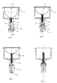
Figure 1 shows a receptacle containing a large size capsule where the rod of the device for sensing the capsule is at the lowest position inside the receptacle. -
Figure 2 shows a receptacle containing a medium size capsule where the rod of the device for sensing the capsule is at a median position inside the receptacle. -
Figure 3 shows a receptacle containing a small size capsule where the rod of the device for sensing the capsule is at a high position inside the receptacle. -
Figure 4 shows an empty receptacle where the rod of the device for sensing the capsule is at a neutral position inside the receptacle. -
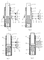
Figure 5 shows a schematic view of optical sensing means based on reflection / absorption of a light beam on a member of the rod passing through a slot in the shaft. -
Figure 6 shows a schematic view of optical sensing means based on light barriers where light beams are interrupted or not by a member of the rod. -
Figure 7 shows a schematic view of optical sensing means based on reflection / absorption of a light beam by the rod through a transparent portion of the shaft. -
Figure 8 shows a schematic view of magnetic sensing means based on reed relays which are switched on or off by a permanent magnet attached on the end of the rod sliding in the shaft. -
Figure 9 shows an embodiment of the device where the rod slides over the shaft which is not attached to the receptacle, the optical sensing means being based on reflection / absorption of a light beam on the rod and on the shaft. - The
figures 1 to 4 illustrate an example of acapsule receptacle 1 which may be used in a beverage preparation system as described inW02010/026053 . The device for sensing thecapsule 2 of the invention is specially designed to be adapted to arotary receptacle 1 exerting centrifugal forces on ingredient inside thecapsule 2. - The
receptacle 1 forms in general a cylindrical or conical wide shaped cavity provided with an upper opening for inserting thecapsule 2 and a lower bottom closing the receptacle. The opening has a diameter slightly larger than the one of the body of thecapsule 2. The outline of the opening fits to the outline of a rim of the capsule configured to lean on the edge of the opening when thecapsule 2 is inserted. The lower bottom is provided with a cylindricalhollow shaft 3 attached perpendicularly to the center of the external face of the bottom. Thereceptacle 1 rotates around the central axis R of thehollow shaft 3. The inner face of the bottom of the receptacle includes a hole at its center communicating with the interior of theshaft 3. - The mechanical part of the sensing device of the invention comprises a
rod 4 passing through the hole at the center of thereceptacle 1 and sliding in theshaft 3. Therod 4 is maintained lifted inside thereceptacle 1 thanks to aspring 8 arranged between a fixed point in theshaft 3 and the end of therod 4 appearing in thereceptacle 1. Depending on the size of the capsule, therod 4 is more or less pushed into theshaft 3 and thespring 8 more or less compressed by the bottom of thecapsule 2 when inserted in place in the receptacle. - When
capsule 2 is not in arranged in thereceptacle 1, therod 4 is at a neutral position i.e. thespring 8 is entirely released without any force pushing therod 4. The position of the end of the rod in theshaft 3 is thus close to the bottom of thereceptacle 1 while the other end is close to the opening. - The arrangement of the capsule in the receptacle requires that a pressure is exerted onto the capsule which is obtained in particular by physically applying a liquid feed assembly (not shown) of the brewing apparatus against the upper surface of the capsule such as described in
W02010/026053 . The liquid feed assembly comprises a surface that applies a certain closure pressure onto the upper surface of the capsule. As a result, thecapsule 2 pushes therod 4 so that the rim of thecapsule 2 leans on the whole outline of the upper edge of thereceptacle 1. -
Figures 1 to 4 illustrate an example of a mechanical realization of therod 4 associated to some mechanical elements enabling its motion according to the size of the capsule in thereceptacle 1. - The
rod 4 is formed by a piece of metallic or plastic tube sliding on acore piece 5 fixed with theshaft 3 of thereceptacle 1. The diameter of thecore piece 5 is determined so that the tube can slide freely inside theshaft 3 between the internal wall of theshaft 3 and the external surface of thecore piece 5. The first end of the tube which is situated inside the receptacle is closed by afree end 10 which external face enters in contact with the bottom of the capsule when inserted in the receptacle. The second end of the tube is provided with at least onemember 6 traversing aslot 7 made in theshaft 3. For balance reasons when rotating, the second end of the tube is provided with at minimum two symmetrically arrangedmembers 6 and theshaft 3 includes correspondingslots 7 also symmetrically arranged around the external surface of theshaft 3. - For reasons linked to the manufacturing process facility and costs, mechanical components such as the shaft, the rod, the core piece, the spring are preferably made on a cylindrical based shape.
- The main role of the
member 6 is to make visible from outside, by the measuring means, the position of the end of therod 4 according to the size or to the presence of thecapsule 2 in thereceptacle 1. Another role is to prevent the disengagement of therod 4 out of theshaft 3 when pulled from thereceptacle 1. Themember 6 abuts against the upper edge of theslot 7 when therod 4 is at the highest position with thespring 8 released. - The
spring 8 is arranged inside the tube between thefree end 10 and the end of thecore piece 5 inside theshaft 3, thecore piece 5 being the fixed support point of thespring 8. The other end of thecore piece 5 closes the end of theshaft 3 and forms acoupling piece 9 for attaching a shaft (not illustrated) of a motor enabling the rotation of thereceptacle 1. - It has to be noted that each mechanical component of the capsule sensing device may be either made up individually of metal or plastic material, i.e. for example when the core piece is metallic, the tube of the rod may be in plastic material or vice versa.
- The measuring means 11 of the position of the
rod 4 are based on optical reading or magnetic sensing of the end of therod 4 sliding in the shaft 3: - The position of the end of the
rod 3 is read by anoptical sensor 12 acting on the member (s) 6 traversing the slot (s) 7 of theshaft 3. Alight beam 13 is projected towards the member (s) 6 withlight sources 14 positioned at different heights along theshaft 3. The visible external parts of themembers 6 are provided with surfaces on which thelight beam 13 is reflected towards cells of alight sensor 15 which provides an electrical signal when receiving a reflected light beam. For each position of therod 4 given by a small, medium, or alarge capsule 2 corresponds anoptical sensor 12 comprising alight source 14 and alight sensor 15. - The
optical sensor 12 consists of alight source 14 with or without focusing optic and alight sensor 15 with or without focusing optic. Thelight source 14 emits either incoherent or coherent (laser) light. The light spectrum may be any, but preferably selected in the infra red band. -
Figure 5 shows a schematic view ofoptical sensors 12 positioned for the three sizes ofcapsules 2 illustrated byfigures 1 to 3 . Thelight beam 13 emitted by alight source 14 of anoptical sensor 12 is either reflected on the external surface of themember 6 traversing theslot 7 or absorbed by the external surface of therod 4 or by the external surface of thecore piece 5 inside theshaft 3. The correspondinglight sensor 15 provides a binary bit "0" or "1" in respect of reflection or absorption of thelight beam 13. - The surfaces entering in contact with light beams are treated in by appropriate material for absorbing or reflecting light in the most optimal conditions. According to the example of
figure 5 , a medium size capsule provides binary code "010", a large size provides "001" and a small size provides "100". When thecapsule 2 is not inserted in thereceptacle 1, themember 6 of therod 4 is at the highest position out of the space monitored by thesensors 12. The light beams 13 are thus all absorbed by thecore piece 5 inside the shaft so that thesensors 15 provide binary code "000". The bits of the code may also be inverted in a configuration of thesensors 15 where a reflection provides bit "0" while absorption provides bit "1 ". - This binary code is transmitted to a control device of the beverage production apparatus managing machine parameters by taking in account the size of the capsules. These parameters are for example the quantity of water, the water temperature, pressure, flow rate of water supplied, and also the rotating speed of the receptacle, etc.
- According to an embodiment shown by
figure 6 , the optical reading of the position of therod 4 may be based on light barriers principle where alight source 14 is placed facing alight sensor 15. For the three sizes of capsules, three pairs of light source and light sensor are required. Thelight sources 14 facing thelight sensors 15 are placed at the levels corresponding to the positions of themember 6 in the vicinity of theshaft 3. The geometry of themember 6 as well as the location of thelight sensors 15 and thelight sources 14 in the vicinity of theshaft 3 are adapted to interrupt or not thelight beam 13 in function of the size of thecapsule 2 depending on the position of therod 3. - The
figure 6 shows an example with a position of therod 3 given by a medium size capsule. In this case thelight beam 13 illuminates the lowest and thehighest light sensor 15 while the sensor at the intermediate position is occulted by themember 6 of therod 3. Amedium size capsule 2 provides thus binary code "101", a large size provides code "110" and a small size provides code "011 ". When thecapsule 2 is removed from thereceptacle 1, therod 3 is at its highest position so that allsensors 15 are illuminated by their respective light beams 13, providing thus code "111 ". As in the preceding embodiment, the bits of the code may be inversed so that an illuminatedsensor 15 provides bit "0" while an occulted one provides bit "1". - According to a further embodiment shown on
figure 7 , a portion of theshaft 3 may be made up of transparent plastic material to make visible to anoptical sensor 12 the end of therod 4 sliding inside theshaft 3. Slots for passing members of the rod are therefore no more necessary in the shaft. They are then replaced byabutments 17 on the inner wall of theshaft 3 configured for preventing disengagement of therod 4. Theabutments 17 are placed at a distance from the end of thecore piece 5 closing theshaft 3 determined by the highest position of therod 4, i.e. the position of therod 4 when thecapsule 2 is removed from thereceptacle 1. Themember 6 at the end of therod 7 sliding in theshaft 3 is thus dimensioned according to the shape and dimensions of theabutments 17 inside theshaft 3. - In a configuration example, the
core piece 5 is coated with a dark light absorbing color and the tube of therod 4 coated in a light reflective color or vice versa to provide suitable contrast for reading the position of therod 4 through the transparent wall of theshaft 3. In another embodiment the coating of therod 4 may cover only an end part of therod 4 while the remaining part is coated with dark color. For both configurations, the position of therod 4 is read byoptical sensors 12 similar to the ones used in the embodiment offigure 5 . Thelight sources 14 and thelight sensors 15 are therefore placed in the vicinity of the transparent portion of theshaft 3. - In the example of
figure 7 , therod 4 is entirely light reflective and thecore piece 5 light absorbent. Amedium size capsule 2 provides binary code "110", a large size provides code "111" and a small size provides code "100". When thecapsule 2 is removed code "000" is provided because the position of therod 4 is out of the space monitored by theoptical sensors 12. The light beams 13 are therefore all absorbed by thecore piece 5. As in the preceding embodiments, the bits of the code may be inverted in a configuration of the sensor where a reflection provides bit "0" while absorption provides bit "1". - In a further embodiment, the transparent portion of the
shaft 3 may be replaced by one or a plurality of slots configured to render visible, by theoptical sensor 12, the end of therod 4 sliding in theshaft 3. - In a further embodiment illustrated by
figure 9 , theshaft 3 is not attached to thereceptacle 1 which rotation is enabled by therod 4 driven by theshaft 3 via thecoupling piece 9 which is attached to a shaft of a motor. - The
rod 4 made up of a tube traverses thereceptacle 1 through a hole at the center of the bottom of thereceptacle 1 and slides over theshaft 3 coaxial to therod 4 and to the rotation axis R. - The shape of the hole as well as the shape of the section of the
rod 4 traversing the hole may be oval or any other shape suitable to drive the rotation of thereceptacle 1 around the axis R. The water tightness between the exterior and the interior of thereceptacle 1 is provided with a joint 22 such as an O-ring having an outline corresponding to the one of the hole. Thespring 8 maintaining the end of therod 4 inside the receptacle is located between the end of theshaft 3 and thefree end 10 of therod 4. The coupling between theshaft 3 and therod 4 is made up of at least onepin 21 sliding in agroove 20 on the inner wall of therod 4. The length of thegroove 20 is determined by the distance covered by therod 4 between its highest position in absence of a capsule in the receptacle and its lowest position reached when the maximal size of capsule is inserted in thereceptacle 1. The lower end of thegroove 20 provides an abutment preventing the disengagement of theshaft 3 from therod 4 by pulling it from thereceptacle 1. For reasons related to balance when rotating, two ormore pins 21 withcorresponding grooves 20 in therod 4 are symmetrically distributed around theshaft 3 respectively in therod 4. -
Figure 9 shows an example where therod 4 is at its highest position and thespring 8 is entirely released in absence of a capsule in thereceptacle 1. The position of the end of therod 4 is read byoptical sensors 11 as in the embodiments offigure 5 or figure 7 . The contrast between theshaft 3 and therod 4 may be improved by an appropriate coating, i.e. therod 4 is coated with light reflective material while theshaft 3 is coated with light absorbent material or vice-versa. - In a further embodiment the optical sensors are replaced by a magnetic sensor using a permanent magnet controlling switches sealed in small watertight glass tubes (reed relays).
- The magnetic sensors consist of reed relay switches 19 arranged at positions along the
shaft 3 corresponding to the different capsule sizes. Theswitches 19 are operated by thepermanent magnet 18 attached to the end of therod 4 sliding in theshaft 3 in respect to the size of thecapsule 2 inserted in thereceptacle 1 or the absence of capsule. - As shown by
figure 8 , apermanent magnet 18 is arranged on the end of therod 4 sliding in theshaft 3. Themagnet 18 may be configured in form of an end piece or a ring surrounding the end of therod 4. Thismagnet 18 may also be used as member to enter in contact withabutments 17 on the inner wall of theshaft 3 configured for preventing disengagement of therod 4. As in the embodiment with the transparent shaft offigure 7 , no slots in the shaft are necessary because the magnetic field traverses non-magnetic materials without being absorbed or deviated. Therefore, in this embodiment, the tube of therod 4, theshaft 3 and thecore piece 5 have to be made in non-magnetic material such as aluminum, brass or plastic material. - The magnetic field of the permanent magnet traverses the
shaft 3 and opens or closes the reed relay switches 19. Theseswitches 19 are placed in an electric circuit connected to the control device of the apparatus and configured to provide a binary code in respect of the position of themagnet 18 at the end of therod 4 sliding inside theshaft 3. - In the example of
figure 8 , the medium size capsule positions themagnet 18 facing theintermediate switch 19 that is closed by the action of the magnetic field. The upper and thelower switch 19 remain open. - A
medium size capsule 2 provides code "010", a large size provides code "001" and a small size provides code "100". When thecapsule 2 is removed code "000" is provided because the position of themagnet 18 is beyond thehighest switch 19 which is then open as the two lower ones. The bits of the code may also be inverted in a configuration of the magnetic sensor where a closed switch provides bit "0" while an open switch provides bit "1". - An advantage of this embodiment, in addition to simplicity, is that the electric consumption is reduced relative to the embodiments with optical sensors requiring electrical power supply for the light source and the light sensors.
- In a further embodiment, the means for providing a code related to the sensed relative position of the surface of the capsule in contact with the rod in the receptacle comprises a potentiometer which measures variable resistances as a function of the relative position of the rod.
- In an example of configuration, one or several contacts slide on the surface of the rod which is coated with resistive material. The contacts may be arranged on a predetermined position on the inner wall of the hollow shaft. The sensor measures values of a voltage or a current varying continuously in function of the relative position of the rod. These analog voltage or current values may be converted into binary values by using voltage or current threshold values corresponding to different sizes of capsules. For example a voltage of 100mV is associated to a small size capsule, 200mV to a medium size and 300mV to a large size. When the receptacle is empty the voltage is at zero. In a further example, the contacts may be attached at a predetermined position on the rod and the inner wall of the hollow shaft is coated with resistive material.
- Although the device has been more particularly described in relation to a beverage production apparatus using centrifugation for extracting liquid from the capsule, it can be part of a beverage production device using pressure by a separate pump or gravity for extracting liquid and in which the receptacle is not rotated around an axis perpendicular to the center of the bottom of the receptacle.
Claims (17)
- Device for sensing a capsule in a beverage production apparatus, comprising a receptacle for receiving said capsule containing beverage ingredient, said receptacle having an upper opening for inserting the capsule and a bottom, the device is characterized in that it comprises at least one means for sensing the relative position of an external surface of the capsule in the receptacle; said relative position being representative of the size of the capsule when the capsule is arranged in the receptacle and means for providing a code which is related to the sensed relative position of said surface.
- Device according to claim 1, wherein said sensing means comprises a retractable sensing plunger arranged to sense the position of the bottom of the capsule.
- Device according to claims 1 or 2, wherein the means for providing a code comprise an optical measuring means, a magnetic sensor or a resistive sensing means for determining the relative position of the sensing means and providing a binary or analogical code.
- Device according to any of claims 1 to 3, wherein the receptacle is arranged to rotate around an axis perpendicular to the bottom of the receptacle.
- Device according to claim 4, wherein the sensing means comprises a rod sliding along a shaft coaxial to the rotation axis and passing through a hole of the inner face of the bottom of the receptacle, said rod being provided with a spring maintaining an end of the rod lifted inside the receptacle, said device further comprising means for measuring the position of the end of the rod sliding along the shaft.
- Device according to claim 5 characterized in that the rod slides inside a cylindrical hollow shaft attached to the receptacle and passes through a hole formed by the shaft at the center of the inner face of the bottom of the receptacle, the rod being provided with a spring maintaining an end of the rod lifted inside the receptacle in contact with the capsule, the other end sliding inside the shaft at positions depending on the size of the capsule.
- Device according to claims 5 or 6, characterized in that in absence of the capsule in the receptacle the rod has a neutral position where the end of the rod inside the receptacle is lifted at the highest position close to the upper opening while the position of other end in the shaft is close to the bottom of the receptacle, the spring being entirely released.
- Device according to anyone of claims 5 to 7, characterized in that the rod is formed by a piece of tube sliding on a core piece integral with the shaft of the receptacle, the diameter of the core piece being determined so that the tube slides freely inside the shaft between the internal wall of the shaft and the external surface of the core piece, the first end of the tube situated inside the receptacle being closed by a free end which external face enters in contact with the bottom of the capsule when inserted in the receptacle, the second end of the tube being provided with at least one member traversing a slot made in the shaft.
- Device according to claim 8, characterized in that the spring is arranged inside the tube between the free end and the end of the core piece inside the shaft, the core piece being the fixed support point of the spring, the other end of the core piece closes the end of the shaft and forms a coupling piece with a shaft of a motor enabling the rotation of the receptacle.
- Device according to anyone of claims 5 to 8, characterized in that the means for measuring the position of the end of the rod in the shaft comprise an optical sensor including a plurality of light sources and a plurality of light sensors each associated to a corresponding light source, each light source positioned at different positions along the shaft projects a light beam on the member of the rod, said member reflecting the light beam towards a corresponding light sensor providing an electrical signal for each position of the rod in respect of the size of the capsule or the absence of the capsule in the receptacle.
- Device according to claim 10, characterized in that the light beam emitted by a light source of the optical sensor is either reflected on an external surface of the member of the rod traversing the slot of the shaft or absorbed by an external surface of the rod or by the external surface of the core piece inside the shaft, the corresponding light sensor providing a binary bit in respect of reflection or absorption of the light beam.
- Device according to anyone of claims 5 to 9, characterized in that the means for measuring the position of the end of the rod in the shaft comprise an optical sensor including a plurality of light sensors and a plurality of light sources, each light sensor being placed facing a light source at the levels corresponding to the positions of the member in the vicinity of the shaft, said member interrupting the light beam between a light source and a light sensor in function of the size of the capsule or the absence of the capsule in the receptacle.
- Device according to claim 12, characterized in that each light sensor provides a binary bit in respect of illumination or occultation by the member of the rod.
- Device according to anyone of claims 5 to 7, characterized in that a portion of the shaft is made up of transparent plastic material to make visible to an optical sensor the end of the rod sliding inside the shaft, said end of the rod being provided with a member sliding in the shaft between the end of the core piece closing the shaft and abutments arranged inside the shaft at a distance determined by the highest position of the rod, the core piece and the rod or the member of the rod being coated either with light reflective or light absorbent material to provide contrast to the light sensors placed in the vicinity of the transparent portion of the shaft.
- Device according to anyone of claims 5 to 7, characterized in that the shaft, the rod and the core piece are made in non magnetic material, the end of the rod sliding inside the shaft being provided with a member including a permanent magnet sliding in the shaft between the end of the core piece closing the shaft and abutments arranged inside the shaft at a distance determined by the highest position of the rod and the means for measuring the position of the end of the rod in the shaft comprise a magnetic sensor including a plurality of reed relay switches arranged at positions along the shaft corresponding to the different capsule sizes, the switches being operated by the permanent magnet attached to the end of the rod sliding in the shaft in respect to the size of the capsule inserted in the receptacle or the absence of capsule.
- Beverage production apparatus comprising a device according to any of the preceding claims.
- Combination of a device according to any of the preceding claims and a capsule containing a beverage ingredient in use, said capsule being arranged in the receptacle and comprising an external surface engaged with the sensing means of the device forming a mutual engagement which is representative of the size of the capsule; a code being produced related to the sensed position of said bottom.
Priority Applications (17)
| Application Number | Priority Date | Filing Date | Title |
|---|---|---|---|
| ES10170042T ES2423295T3 (en) | 2010-07-19 | 2010-07-19 | Device for detecting a capsule in a beverage production apparatus |
| PL10170042T PL2409608T3 (en) | 2010-07-19 | 2010-07-19 | Device for sensing a capsule in a beverage production apparatus |
| DK10170042.5T DK2409608T3 (en) | 2010-07-19 | 2010-07-19 | Device for sensing a capsule in a beverage maker |
| EP10170042.5A EP2409608B1 (en) | 2010-07-19 | 2010-07-19 | Device for sensing a capsule in a beverage production apparatus |
| PT101700425T PT2409608E (en) | 2010-07-19 | 2010-07-19 | Device for sensing a capsule in a beverage production apparatus |
| EP11743795.4A EP2595515A1 (en) | 2010-07-19 | 2011-07-13 | Device for sensing a capsule in a beverage production apparatus |
| CA2805032A CA2805032A1 (en) | 2010-07-19 | 2011-07-13 | Device for sensing a capsule in a beverage production apparatus |
| JP2013520064A JP5881699B2 (en) | 2010-07-19 | 2011-07-13 | Equipment for detecting capsules in beverage production equipment |
| BR112013001407A BR112013001407A2 (en) | 2010-07-19 | 2011-07-13 | device for perceiving a capsule in a beverage production apparatus |
| AU2011281800A AU2011281800A1 (en) | 2010-07-19 | 2011-07-13 | Device for sensing a capsule in a beverage production apparatus |
| PCT/EP2011/061913 WO2012010470A1 (en) | 2010-07-19 | 2011-07-13 | Device for sensing a capsule in a beverage production apparatus |
| US13/811,111 US8836956B2 (en) | 2010-07-19 | 2011-07-13 | Device for sensing a capsule in a beverage production apparatus |
| CN201180042707.3A CN103096767B (en) | 2010-07-19 | 2011-07-13 | For sensing the device of the capsule in beverage production device |
| RU2013107026/12A RU2563224C2 (en) | 2010-07-19 | 2011-07-13 | Device for identification of capsule in beverage making machine |
| HK12106744.2A HK1165968B (en) | 2012-07-10 | Device for sensing a capsule in a beverage production apparatus | |
| ZA2013/01244A ZA201301244B (en) | 2010-07-19 | 2013-02-18 | Device for sensing a capsule in a beverage production apparatus |
| US14/450,900 US9255819B2 (en) | 2010-07-19 | 2014-08-04 | Device for sensing a capsule in a beverage production apparatus |
Applications Claiming Priority (1)
| Application Number | Priority Date | Filing Date | Title |
|---|---|---|---|
| EP10170042.5A EP2409608B1 (en) | 2010-07-19 | 2010-07-19 | Device for sensing a capsule in a beverage production apparatus |
Publications (2)
| Publication Number | Publication Date |
|---|---|
| EP2409608A1 true EP2409608A1 (en) | 2012-01-25 |
| EP2409608B1 EP2409608B1 (en) | 2013-05-29 |
Family
ID=43981113
Family Applications (2)
| Application Number | Title | Priority Date | Filing Date |
|---|---|---|---|
| EP10170042.5A Not-in-force EP2409608B1 (en) | 2010-07-19 | 2010-07-19 | Device for sensing a capsule in a beverage production apparatus |
| EP11743795.4A Withdrawn EP2595515A1 (en) | 2010-07-19 | 2011-07-13 | Device for sensing a capsule in a beverage production apparatus |
Family Applications After (1)
| Application Number | Title | Priority Date | Filing Date |
|---|---|---|---|
| EP11743795.4A Withdrawn EP2595515A1 (en) | 2010-07-19 | 2011-07-13 | Device for sensing a capsule in a beverage production apparatus |
Country Status (14)
| Country | Link |
|---|---|
| US (2) | US8836956B2 (en) |
| EP (2) | EP2409608B1 (en) |
| JP (1) | JP5881699B2 (en) |
| CN (1) | CN103096767B (en) |
| AU (1) | AU2011281800A1 (en) |
| BR (1) | BR112013001407A2 (en) |
| CA (1) | CA2805032A1 (en) |
| DK (1) | DK2409608T3 (en) |
| ES (1) | ES2423295T3 (en) |
| PL (1) | PL2409608T3 (en) |
| PT (1) | PT2409608E (en) |
| RU (1) | RU2563224C2 (en) |
| WO (1) | WO2012010470A1 (en) |
| ZA (1) | ZA201301244B (en) |
Cited By (28)
| Publication number | Priority date | Publication date | Assignee | Title |
|---|---|---|---|---|
| WO2014056730A1 (en) * | 2012-10-09 | 2014-04-17 | Nestec S.A. | Beverage preparation machine with capsule size detection |
| WO2014096121A1 (en) * | 2012-12-19 | 2014-06-26 | Nestec S.A. | Sensor for multi-size cartridge extraction unit |
| WO2014096120A1 (en) * | 2012-12-19 | 2014-06-26 | Nestec S.A. | Self-locking multi-size cartridge extraction unit |
| WO2014186897A1 (en) * | 2013-05-23 | 2014-11-27 | 2266170 Ontario Inc. | Capsule housing |
| WO2015091193A1 (en) * | 2013-12-20 | 2015-06-25 | Koninklijke Philips N.V. | Consumable recognition system, set of consumables and beverage dispenser |
| WO2016127126A1 (en) * | 2015-02-05 | 2016-08-11 | Remington Designs, Llc | Devices and methods for beverage brewer regulation |
| CN106066150A (en) * | 2015-04-24 | 2016-11-02 | 株式会社堀场Stec | Micro-location gap sensor assembly |
| WO2016193381A1 (en) * | 2015-06-04 | 2016-12-08 | Arcelik Anonim Sirketi | A coffee machine and a capsule suitable to be used in coffee machines |
| EP3195766A1 (en) * | 2016-01-25 | 2017-07-26 | Eugster/Frismag AG | Beverage preparation device, system and method of operation |
| US9801494B2 (en) | 2012-04-11 | 2017-10-31 | Koninklijke Philips N.V. | Capsule adapter and system using said capsule adapter |
| GB2567686A (en) * | 2017-10-20 | 2019-04-24 | Vi Healthy Living Ltd | Dispensing apparatus |
| US10314319B2 (en) | 2013-11-20 | 2019-06-11 | 2266170 Ontario Inc. | Method and apparatus for accelerated or controlled degassing of roasted coffee |
| US10336531B2 (en) | 2014-03-21 | 2019-07-02 | 2266170 Ontario Inc. | Capsule with steeping chamber |
| US10351277B2 (en) | 2013-08-20 | 2019-07-16 | 2266170 Ontario Inc. | Process for making a capsule containing a dosing agent |
| WO2021028472A1 (en) * | 2019-08-13 | 2021-02-18 | Eugster / Frismag Ag | Beverage preparation apparatus and method for preparing a beverage using a single-serve capsule of a first and a second type, and system comprising a beverage preparation apparatus and a single-serve capsule set. |
| US10966564B2 (en) | 2016-08-03 | 2021-04-06 | Koninklijke Douwe Egberts B.V. | System for preparing a quantity of beverage suitable for consumption |
| US11096516B2 (en) | 2016-08-03 | 2021-08-24 | Koninklijke Douwe Egberts B.V. | System, apparatus, method, capsule and kit of capsules for preparing a beverage |
| US11129493B2 (en) | 2016-08-03 | 2021-09-28 | Koninklijke Douwe Egberts B.V. | System for preparing a beverage |
| US11129492B2 (en) | 2016-08-03 | 2021-09-28 | Koninklijke Douwe Egberts B.V. | System for preparing a beverage |
| US11197574B2 (en) | 2016-08-03 | 2021-12-14 | Koninklijke Douwe Egberts B.V. | System and method for preparing a beverage field and background |
| US11304555B2 (en) | 2016-08-03 | 2022-04-19 | Koninklijke Douwe Egberts B.V. | System and apparatus for preparing a beverage |
| US11395557B2 (en) | 2016-08-03 | 2022-07-26 | Koninklijke Douwe Egberts B.V. | Apparatus and method for preparing a beverage and system comprising the apparatus and an exchangeable capsule |
| US11576519B2 (en) | 2016-08-03 | 2023-02-14 | Koninklijke Douwe Egberts B.V. | System, apparatus, method, capsule and kit of capsules for preparing a beverage |
| WO2023104444A1 (en) * | 2021-12-07 | 2023-06-15 | Melitta Single Portions Gmbh & Co. Kg | Machine and method for preparing a brewed drink |
| US11944230B2 (en) | 2018-12-12 | 2024-04-02 | Koninklijke Douwe Egberts B.V. | Air purge groove |
| US12161249B2 (en) | 2016-08-03 | 2024-12-10 | Koninklijke Douwe Egberts B.V. | System for preparing a beverage |
| US12295521B2 (en) | 2016-08-03 | 2025-05-13 | Koninklijke Douwe Egberts B.V. | System for preparing a beverage |
| WO2025193657A1 (en) * | 2024-03-12 | 2025-09-18 | Keurig Green Mountain, Inc. | Beverage machine with beverage tablet size detection |
Families Citing this family (41)
| Publication number | Priority date | Publication date | Assignee | Title |
|---|---|---|---|---|
| DE202011001661U1 (en) * | 2011-01-19 | 2011-06-09 | Mahlich, Gotthard, 61476 | Brewing or preparation chamber for a beverage preparation device |
| US9428328B2 (en) | 2011-09-01 | 2016-08-30 | 2266170 Ontario Inc. | Beverage capsule |
| ITVR20110179A1 (en) * | 2011-09-19 | 2013-03-20 | Caffita System Spa | INFUSION DEVICE FOR THE PRODUCTION OF DRINKS BY USING CARTRIDGES, WHICH CARTRIDGES OR PODS |
| ITVR20110180A1 (en) * | 2011-09-19 | 2013-03-20 | Caffita System Spa | INFUSION DEVICE FOR THE PRODUCTION OF DRINKS BY USING CARTRIDGES, WHICH CAPSULES OR PODS |
| GB2499496B (en) | 2012-12-19 | 2014-11-19 | Kraft Foods R & D Inc | A method of dispensing a beverage, a beverage preparation machine, and a system |
| EP3076833B1 (en) * | 2013-12-06 | 2018-11-21 | Nestec S.A. | Device guiding differently sized capsules to extraction |
| RU2659909C1 (en) * | 2013-12-20 | 2018-07-04 | Конинклейке Филипс Н.В. | Consumable recognition system and beverage dispenser |
| CN105813519B (en) * | 2013-12-20 | 2019-12-20 | 皇家飞利浦有限公司 | Consumable set and beverage dispenser |
| US10136754B2 (en) | 2014-01-17 | 2018-11-27 | Keurig Green Mountain, Inc. | Beverage machine cartridge holder |
| US9474406B2 (en) | 2014-01-17 | 2016-10-25 | Keurig Green Mountain, Inc. | Apparatus with beverage cartridge holder having movable outlet |
| US10132655B2 (en) | 2014-05-12 | 2018-11-20 | Phaedrus, Llc | Apparatus, system and method for detecting a position of a movable object in a device and using the same for controlling the device |
| US11512985B2 (en) | 2014-05-12 | 2022-11-29 | Phaedrus, Llc | Control system and method for detecting a position of a movable object |
| DE102014108522A1 (en) * | 2014-06-17 | 2015-12-17 | Miele & Cie. Kg | Automat for making an infusion beverage |
| CN104146606B (en) * | 2014-07-11 | 2016-05-11 | 浙江酷菲尔电器有限公司 | A kind of multifunctional coffee-making machine |
| DE102014109768B4 (en) * | 2014-07-11 | 2019-01-24 | Melitta Single Portions Gmbh & Co. Kg | Apparatus for preparing brewed beverages, capsule, capsule system and method for producing a brewing beverage |
| DE102014109761B4 (en) | 2014-07-11 | 2020-07-09 | Melitta Single Portions Gmbh & Co. Kg | Device and method for preparing a brewed beverage |
| US9880051B2 (en) | 2014-08-26 | 2018-01-30 | Siemens Aktiengesellschaft | Sealing system for optical sensors in gas turbine engines |
| US10059464B2 (en) | 2014-10-15 | 2018-08-28 | Sikorsky Aircraft Corporation | Position sensor system for a landing gear assembly and method of monitoring |
| DE102016103325B4 (en) | 2016-02-25 | 2025-03-20 | Infineon Technologies Ag | Magnetic angular position sensor |
| ITUA20161450A1 (en) * | 2016-03-08 | 2017-09-08 | Capitani Srl | CAPSULE CONTAINER |
| CA3041722A1 (en) | 2016-11-09 | 2018-05-17 | Pepsico, Inc. | Carbonated beverage makers, methods, and systems |
| US10470605B2 (en) | 2017-04-21 | 2019-11-12 | Whirlpool Corporation | Single-serving beverage machine with high-capacity and compact cooling-carbonation system |
| CN110160564B (en) * | 2018-02-06 | 2021-02-02 | 重庆熵臻科技有限公司 | Portable and stable photoelectric detection detector |
| US20210000283A1 (en) * | 2018-03-15 | 2021-01-07 | Coffee Solutions Llc | Beverge maker with cartridge recognition |
| RU2020134366A (en) | 2018-03-21 | 2022-04-22 | Пресижн Плэнтинг Ллк | REAGENT CARTRIDGE |
| EP3542687A1 (en) * | 2018-03-22 | 2019-09-25 | Koninklijke Philips N.V. | A food processing apparatus |
| WO2020201469A1 (en) | 2019-04-05 | 2020-10-08 | Société des Produits Nestlé SA | Beverage preparation device with thermally optimised architecture |
| CA3141941A1 (en) | 2019-06-20 | 2020-12-24 | Societe Des Produits Nestle Sa | Beverage preparation device with simple multi-thermal conditioning |
| WO2021122492A1 (en) | 2019-12-16 | 2021-06-24 | Société des Produits Nestlé SA | Fluid line external to outside beverage machine housing |
| WO2021122502A1 (en) | 2019-12-16 | 2021-06-24 | Société des Produits Nestlé SA | Beverage machine with actuated water supply valve |
| US20230024311A1 (en) | 2019-12-16 | 2023-01-26 | Societe Des Produits Nestle S.A. | Beverage machine carriable single-handed |
| EP4076102A1 (en) | 2019-12-16 | 2022-10-26 | Société des Produits Nestlé S.A. | Beverage machine with visible beverage management |
| US20230027842A1 (en) | 2019-12-16 | 2023-01-26 | Societe Des Produits Nestle S.A. | Beverage machine with separable beverage processing unit |
| WO2021122493A1 (en) | 2019-12-16 | 2021-06-24 | Société des Produits Nestlé SA | Beverage machine with an off-set actuator |
| CN114828700A (en) | 2019-12-16 | 2022-07-29 | 雀巢产品有限公司 | Beverage machine with beverage collector |
| WO2021122498A1 (en) | 2019-12-16 | 2021-06-24 | Société des Produits Nestlé SA | Thermally unconditionned beverage preparation machine |
| US12599265B2 (en) | 2019-12-16 | 2026-04-14 | Societe Des Produits Nestle S.A. | Beverage machine with separable fluid module |
| CN114745993A (en) | 2019-12-16 | 2022-07-12 | 雀巢产品有限公司 | Beverage machine with simple water drive |
| WO2021191107A1 (en) | 2020-03-24 | 2021-09-30 | Société des Produits Nestlé SA | Beverage preparation machine with handy power management |
| EP4213687A1 (en) * | 2020-09-15 | 2023-07-26 | Société des Produits Nestlé S.A. | Beverage preparation machine with control based on deformation of an extraction head frame structure and method to control the machine based on said deformation |
| GB2605160B (en) * | 2021-03-24 | 2023-05-31 | Safran Landing Systems Uk Ltd | Aircraft landing gear torque link assembly |
Citations (4)
| Publication number | Priority date | Publication date | Assignee | Title |
|---|---|---|---|---|
| US20070104837A1 (en) * | 2000-11-28 | 2007-05-10 | Alfred Yoakim | Methods of preparing a food product from a cartridge |
| US20080187638A1 (en) * | 2004-07-27 | 2008-08-07 | Nick Hansen | Cartridge, a Machine, a System and a Method for the Preparation of Beverages |
| WO2010026053A1 (en) | 2008-09-02 | 2010-03-11 | Nestec S.A. | Controlled beverage production device using centrifugal forces |
| US20100147157A1 (en) * | 2007-05-18 | 2010-06-17 | Roger Geoffrey Tanner | Improvements In or Relating to Beverage Preparation Machines |
Family Cites Families (15)
| Publication number | Priority date | Publication date | Assignee | Title |
|---|---|---|---|---|
| JPS553876A (en) * | 1978-06-27 | 1980-01-11 | Toray Ind Inc | Apparatus for adding substance to vessel |
| US20020048621A1 (en) * | 2000-10-06 | 2002-04-25 | Boyd David D. | Encoded coffee packet |
| WO2003030696A1 (en) * | 2001-10-05 | 2003-04-17 | Hp Intellectual Corp. | Coffee maker |
| RU2299666C2 (en) * | 2002-10-03 | 2007-05-27 | Туттоэспрессо С.П.А. | Method and apparatus for preparing of beverages from soluble products |
| ATE529027T1 (en) * | 2003-08-25 | 2011-11-15 | Nestec Sa | METHOD AND DEVICE FOR PRODUCING A BEVERAGE FROM A CAPSULE CONTAINING A SUBSTANCE |
| DE102004002004A1 (en) * | 2004-01-14 | 2005-08-11 | Schifferle, René | Coffee machine for brewing coffee powder packaged in a capsule |
| FR2873011B1 (en) * | 2004-07-16 | 2007-12-14 | Reneka Internat Sarl | PREPARATION GROUP OF AT LEAST ONE EXPRESSO TYPE COFFEE CUP OR OTHER HOT BEVERAGE FROM A PREEMBALLED INDIVIDUAL DOSE CALLED DOSETTE |
| PL1656863T3 (en) * | 2004-11-11 | 2011-07-29 | Nestec Sa | Self-cleaning mixing head for producing a milk-based mixture and beverage production machines comprising such a mixing head |
| US20060254428A1 (en) * | 2005-05-14 | 2006-11-16 | Glucksman Dov Z | Coffee making apparatus |
| CN200984099Y (en) * | 2005-12-21 | 2007-12-05 | 皇家飞利浦电子股份有限公司 | Cylinder for prepairng beverage, machine for prepairng beverage and system for prepairng beverage |
| US7950842B2 (en) * | 2007-03-05 | 2011-05-31 | Hamilton Beach Brands, Inc. | Durability monitoring and improvement of a blender |
| EP1974638A1 (en) * | 2007-03-29 | 2008-10-01 | Tchibo GmbH | System with a drinks dispensing machine and with portion capsules |
| EP2071988B1 (en) * | 2007-12-18 | 2011-03-02 | Nestec S.A. | Device for preparing a beverage with removable injection member |
| CA2725362C (en) * | 2008-04-24 | 2017-03-28 | Tconcept Company S.P.R.L. | Capsule, device, and method for preparing infused beverages |
| EP2228633B1 (en) * | 2009-03-10 | 2017-07-05 | Nestec S.A. | Optical level detector for a beverage machine |
-
2010
- 2010-07-19 ES ES10170042T patent/ES2423295T3/en active Active
- 2010-07-19 EP EP10170042.5A patent/EP2409608B1/en not_active Not-in-force
- 2010-07-19 PT PT101700425T patent/PT2409608E/en unknown
- 2010-07-19 DK DK10170042.5T patent/DK2409608T3/en active
- 2010-07-19 PL PL10170042T patent/PL2409608T3/en unknown
-
2011
- 2011-07-13 US US13/811,111 patent/US8836956B2/en active Active
- 2011-07-13 WO PCT/EP2011/061913 patent/WO2012010470A1/en not_active Ceased
- 2011-07-13 BR BR112013001407A patent/BR112013001407A2/en not_active IP Right Cessation
- 2011-07-13 EP EP11743795.4A patent/EP2595515A1/en not_active Withdrawn
- 2011-07-13 CN CN201180042707.3A patent/CN103096767B/en not_active Expired - Fee Related
- 2011-07-13 RU RU2013107026/12A patent/RU2563224C2/en not_active IP Right Cessation
- 2011-07-13 AU AU2011281800A patent/AU2011281800A1/en not_active Abandoned
- 2011-07-13 JP JP2013520064A patent/JP5881699B2/en not_active Expired - Fee Related
- 2011-07-13 CA CA2805032A patent/CA2805032A1/en not_active Abandoned
-
2013
- 2013-02-18 ZA ZA2013/01244A patent/ZA201301244B/en unknown
-
2014
- 2014-08-04 US US14/450,900 patent/US9255819B2/en active Active
Patent Citations (4)
| Publication number | Priority date | Publication date | Assignee | Title |
|---|---|---|---|---|
| US20070104837A1 (en) * | 2000-11-28 | 2007-05-10 | Alfred Yoakim | Methods of preparing a food product from a cartridge |
| US20080187638A1 (en) * | 2004-07-27 | 2008-08-07 | Nick Hansen | Cartridge, a Machine, a System and a Method for the Preparation of Beverages |
| US20100147157A1 (en) * | 2007-05-18 | 2010-06-17 | Roger Geoffrey Tanner | Improvements In or Relating to Beverage Preparation Machines |
| WO2010026053A1 (en) | 2008-09-02 | 2010-03-11 | Nestec S.A. | Controlled beverage production device using centrifugal forces |
Cited By (44)
| Publication number | Priority date | Publication date | Assignee | Title |
|---|---|---|---|---|
| US9801494B2 (en) | 2012-04-11 | 2017-10-31 | Koninklijke Philips N.V. | Capsule adapter and system using said capsule adapter |
| US20150272380A1 (en) * | 2012-10-09 | 2015-10-01 | Nestec S.A. | Beverage preparation machine with capsule size detection |
| WO2014056730A1 (en) * | 2012-10-09 | 2014-04-17 | Nestec S.A. | Beverage preparation machine with capsule size detection |
| US10070749B2 (en) | 2012-12-19 | 2018-09-11 | Nestec S.A. | Sensor for multi-size cartridge extraction unit |
| WO2014096121A1 (en) * | 2012-12-19 | 2014-06-26 | Nestec S.A. | Sensor for multi-size cartridge extraction unit |
| US9986869B2 (en) | 2012-12-19 | 2018-06-05 | Nestec S.A. | Self-locking multi-size cartridge extraction unit |
| WO2014096120A1 (en) * | 2012-12-19 | 2014-06-26 | Nestec S.A. | Self-locking multi-size cartridge extraction unit |
| EP3701841A1 (en) * | 2012-12-19 | 2020-09-02 | Société des Produits Nestlé S.A. | Self-locking multi-size cartridge extraction unit |
| WO2014186897A1 (en) * | 2013-05-23 | 2014-11-27 | 2266170 Ontario Inc. | Capsule housing |
| US10154752B2 (en) | 2013-05-23 | 2018-12-18 | 2266170 Ontario Inc. | Capsule housing |
| US10611507B2 (en) | 2013-08-20 | 2020-04-07 | 2266170 Ontario Inc. | Capsule with control member |
| US10351277B2 (en) | 2013-08-20 | 2019-07-16 | 2266170 Ontario Inc. | Process for making a capsule containing a dosing agent |
| US10314319B2 (en) | 2013-11-20 | 2019-06-11 | 2266170 Ontario Inc. | Method and apparatus for accelerated or controlled degassing of roasted coffee |
| US11304557B2 (en) | 2013-12-20 | 2022-04-19 | Koninklijke Philips N.V. | Consumable recognition system, set of consumables and beverage dispenser |
| WO2015091193A1 (en) * | 2013-12-20 | 2015-06-25 | Koninklijke Philips N.V. | Consumable recognition system, set of consumables and beverage dispenser |
| RU2668070C1 (en) * | 2013-12-20 | 2018-09-25 | Конинклейке Филипс Н.В. | Consumable recognition system, set of consumables and beverage dispenser |
| US10588451B2 (en) | 2013-12-20 | 2020-03-17 | Koninklijke Philips N.V. | Consumable recognition system, set of consumables and beverage dispenser |
| US10336531B2 (en) | 2014-03-21 | 2019-07-02 | 2266170 Ontario Inc. | Capsule with steeping chamber |
| US10716430B2 (en) | 2015-02-05 | 2020-07-21 | Coffee Solutions, Llc | Devices and methods for beverage brewer regulation |
| WO2016127126A1 (en) * | 2015-02-05 | 2016-08-11 | Remington Designs, Llc | Devices and methods for beverage brewer regulation |
| CN106066150B (en) * | 2015-04-24 | 2019-06-04 | 株式会社堀场Stec | Micro- position gap sensor module |
| CN106066150A (en) * | 2015-04-24 | 2016-11-02 | 株式会社堀场Stec | Micro-location gap sensor assembly |
| WO2016193381A1 (en) * | 2015-06-04 | 2016-12-08 | Arcelik Anonim Sirketi | A coffee machine and a capsule suitable to be used in coffee machines |
| EP3195766A1 (en) * | 2016-01-25 | 2017-07-26 | Eugster/Frismag AG | Beverage preparation device, system and method of operation |
| US11304555B2 (en) | 2016-08-03 | 2022-04-19 | Koninklijke Douwe Egberts B.V. | System and apparatus for preparing a beverage |
| US11576519B2 (en) | 2016-08-03 | 2023-02-14 | Koninklijke Douwe Egberts B.V. | System, apparatus, method, capsule and kit of capsules for preparing a beverage |
| US11096516B2 (en) | 2016-08-03 | 2021-08-24 | Koninklijke Douwe Egberts B.V. | System, apparatus, method, capsule and kit of capsules for preparing a beverage |
| US11129493B2 (en) | 2016-08-03 | 2021-09-28 | Koninklijke Douwe Egberts B.V. | System for preparing a beverage |
| US11129492B2 (en) | 2016-08-03 | 2021-09-28 | Koninklijke Douwe Egberts B.V. | System for preparing a beverage |
| US11197574B2 (en) | 2016-08-03 | 2021-12-14 | Koninklijke Douwe Egberts B.V. | System and method for preparing a beverage field and background |
| US12402749B2 (en) | 2016-08-03 | 2025-09-02 | Koninklijke Douwe Egberts B.V. | System, apparatus, method, capsule and kit of capsules for preparing a beverage |
| US12295521B2 (en) | 2016-08-03 | 2025-05-13 | Koninklijke Douwe Egberts B.V. | System for preparing a beverage |
| US11395557B2 (en) | 2016-08-03 | 2022-07-26 | Koninklijke Douwe Egberts B.V. | Apparatus and method for preparing a beverage and system comprising the apparatus and an exchangeable capsule |
| US10966564B2 (en) | 2016-08-03 | 2021-04-06 | Koninklijke Douwe Egberts B.V. | System for preparing a quantity of beverage suitable for consumption |
| US12161249B2 (en) | 2016-08-03 | 2024-12-10 | Koninklijke Douwe Egberts B.V. | System for preparing a beverage |
| US11622568B2 (en) | 2017-10-20 | 2023-04-11 | Vi Healthy Living Ltd. | Dispensing apparatus |
| US12239145B2 (en) | 2017-10-20 | 2025-03-04 | Vi Healthy Living Ltd. | Dispensing apparatus |
| GB2567686A (en) * | 2017-10-20 | 2019-04-24 | Vi Healthy Living Ltd | Dispensing apparatus |
| US11944230B2 (en) | 2018-12-12 | 2024-04-02 | Koninklijke Douwe Egberts B.V. | Air purge groove |
| WO2021028472A1 (en) * | 2019-08-13 | 2021-02-18 | Eugster / Frismag Ag | Beverage preparation apparatus and method for preparing a beverage using a single-serve capsule of a first and a second type, and system comprising a beverage preparation apparatus and a single-serve capsule set. |
| US12426736B2 (en) | 2019-08-13 | 2025-09-30 | Eugster / Frismag Ag | Beverage preparation apparatus and method |
| AU2020328172B2 (en) * | 2019-08-13 | 2026-02-05 | Eugster / Frismag Ag | Beverage preparation apparatus and method for preparing a beverage using a single-serve capsule of a first and a second type, and system comprising a beverage preparation apparatus and a single-serve capsule set. |
| WO2023104444A1 (en) * | 2021-12-07 | 2023-06-15 | Melitta Single Portions Gmbh & Co. Kg | Machine and method for preparing a brewed drink |
| WO2025193657A1 (en) * | 2024-03-12 | 2025-09-18 | Keurig Green Mountain, Inc. | Beverage machine with beverage tablet size detection |
Also Published As
| Publication number | Publication date |
|---|---|
| EP2595515A1 (en) | 2013-05-29 |
| DK2409608T3 (en) | 2013-07-22 |
| CN103096767B (en) | 2016-03-09 |
| RU2563224C2 (en) | 2015-09-20 |
| ES2423295T3 (en) | 2013-09-19 |
| CA2805032A1 (en) | 2012-01-26 |
| JP2013532498A (en) | 2013-08-19 |
| JP5881699B2 (en) | 2016-03-09 |
| US20130114089A1 (en) | 2013-05-09 |
| PT2409608E (en) | 2013-07-26 |
| BR112013001407A2 (en) | 2016-05-24 |
| EP2409608B1 (en) | 2013-05-29 |
| ZA201301244B (en) | 2014-07-30 |
| AU2011281800A1 (en) | 2013-01-24 |
| HK1165968A1 (en) | 2012-10-19 |
| US9255819B2 (en) | 2016-02-09 |
| RU2013107026A (en) | 2014-08-27 |
| PL2409608T3 (en) | 2013-09-30 |
| US8836956B2 (en) | 2014-09-16 |
| WO2012010470A1 (en) | 2012-01-26 |
| CN103096767A (en) | 2013-05-08 |
| US20140340078A1 (en) | 2014-11-20 |
Similar Documents
| Publication | Publication Date | Title |
|---|---|---|
| EP2409608B1 (en) | Device for sensing a capsule in a beverage production apparatus | |
| ES2669576T3 (en) | Capsule processing unit of a beverage preparation machine | |
| ES2595406T3 (en) | Capsule, system and method to prepare a beverage by centrifugation | |
| KR102208015B1 (en) | Capsule, beverage preparation system and method for reading a code on a capsule | |
| AU2020379292B2 (en) | Apparatus for making a beverage using a capsule containing a food substance | |
| AU2002310977B2 (en) | Espresso brewing device | |
| RU2709779C2 (en) | Device and methods for dispensing from beverage preparation machine | |
| EP2906089B1 (en) | Beverage machine | |
| PT3047765T (en) | Support and capsule for preparing a beverage by centrifugation, system and method for preparing a beverage by centrifugation | |
| KR20140095528A (en) | Optical readable code support and capsule for preparing a beverage having such code support providing an enhanced readable optical signal | |
| JP2008259851A (en) | System comprising beverage machine and comprising portion capsule | |
| HK1165968B (en) | Device for sensing a capsule in a beverage production apparatus | |
| US20200278232A1 (en) | Container and device for dispensing fluid |
Legal Events
| Date | Code | Title | Description |
|---|---|---|---|
| AK | Designated contracting states |
Kind code of ref document: A1 Designated state(s): AL AT BE BG CH CY CZ DE DK EE ES FI FR GB GR HR HU IE IS IT LI LT LU LV MC MK MT NL NO PL PT RO SE SI SK SM TR |
|
| AX | Request for extension of the european patent |
Extension state: BA ME RS |
|
| PUAI | Public reference made under article 153(3) epc to a published international application that has entered the european phase |
Free format text: ORIGINAL CODE: 0009012 |
|
| 17P | Request for examination filed |
Effective date: 20120321 |
|
| REG | Reference to a national code |
Ref country code: HK Ref legal event code: DE Ref document number: 1165968 Country of ref document: HK |
|
| GRAP | Despatch of communication of intention to grant a patent |
Free format text: ORIGINAL CODE: EPIDOSNIGR1 |
|
| RIC1 | Information provided on ipc code assigned before grant |
Ipc: A47J 31/36 20060101ALN20121213BHEP Ipc: A47J 31/06 20060101AFI20121213BHEP Ipc: A47J 31/52 20060101ALI20121213BHEP |
|
| GRAS | Grant fee paid |
Free format text: ORIGINAL CODE: EPIDOSNIGR3 |
|
| GRAA | (expected) grant |
Free format text: ORIGINAL CODE: 0009210 |
|
| AK | Designated contracting states |
Kind code of ref document: B1 Designated state(s): AL AT BE BG CH CY CZ DE DK EE ES FI FR GB GR HR HU IE IS IT LI LT LU LV MC MK MT NL NO PL PT RO SE SI SK SM TR |
|
| REG | Reference to a national code |
Ref country code: GB Ref legal event code: FG4D |
|
| REG | Reference to a national code |
Ref country code: CH Ref legal event code: EP |
|
| REG | Reference to a national code |
Ref country code: AT Ref legal event code: REF Ref document number: 613839 Country of ref document: AT Kind code of ref document: T Effective date: 20130615 |
|
| REG | Reference to a national code |
Ref country code: IE Ref legal event code: FG4D |
|
| REG | Reference to a national code |
Ref country code: DK Ref legal event code: T3 |
|
| REG | Reference to a national code |
Ref country code: DE Ref legal event code: R096 Ref document number: 602010007246 Country of ref document: DE Effective date: 20130725 |
|
| REG | Reference to a national code |
Ref country code: PT Ref legal event code: SC4A Free format text: AVAILABILITY OF NATIONAL TRANSLATION Effective date: 20130719 |
|
| REG | Reference to a national code |
Ref country code: SE Ref legal event code: TRGR |
|
| REG | Reference to a national code |
Ref country code: ES Ref legal event code: FG2A Ref document number: 2423295 Country of ref document: ES Kind code of ref document: T3 Effective date: 20130919 |
|
| REG | Reference to a national code |
Ref country code: NO Ref legal event code: T2 Effective date: 20130529 |
|
| REG | Reference to a national code |
Ref country code: PL Ref legal event code: T3 |
|
| REG | Reference to a national code |
Ref country code: NL Ref legal event code: T3 |
|
| REG | Reference to a national code |
Ref country code: GR Ref legal event code: EP Ref document number: 20130401649 Country of ref document: GR Effective date: 20130920 |
|
| REG | Reference to a national code |
Ref country code: HK Ref legal event code: GR Ref document number: 1165968 Country of ref document: HK |
|
| REG | Reference to a national code |
Ref country code: LT Ref legal event code: MG4D |
|
| PG25 | Lapsed in a contracting state [announced via postgrant information from national office to epo] |
Ref country code: SI Free format text: LAPSE BECAUSE OF FAILURE TO SUBMIT A TRANSLATION OF THE DESCRIPTION OR TO PAY THE FEE WITHIN THE PRESCRIBED TIME-LIMIT Effective date: 20130529 Ref country code: IS Free format text: LAPSE BECAUSE OF FAILURE TO SUBMIT A TRANSLATION OF THE DESCRIPTION OR TO PAY THE FEE WITHIN THE PRESCRIBED TIME-LIMIT Effective date: 20130929 Ref country code: LT Free format text: LAPSE BECAUSE OF FAILURE TO SUBMIT A TRANSLATION OF THE DESCRIPTION OR TO PAY THE FEE WITHIN THE PRESCRIBED TIME-LIMIT Effective date: 20130529 |
|
| PG25 | Lapsed in a contracting state [announced via postgrant information from national office to epo] |
Ref country code: BG Free format text: LAPSE BECAUSE OF FAILURE TO SUBMIT A TRANSLATION OF THE DESCRIPTION OR TO PAY THE FEE WITHIN THE PRESCRIBED TIME-LIMIT Effective date: 20130829 Ref country code: HR Free format text: LAPSE BECAUSE OF FAILURE TO SUBMIT A TRANSLATION OF THE DESCRIPTION OR TO PAY THE FEE WITHIN THE PRESCRIBED TIME-LIMIT Effective date: 20130529 |
|
| PG25 | Lapsed in a contracting state [announced via postgrant information from national office to epo] |
Ref country code: LV Free format text: LAPSE BECAUSE OF FAILURE TO SUBMIT A TRANSLATION OF THE DESCRIPTION OR TO PAY THE FEE WITHIN THE PRESCRIBED TIME-LIMIT Effective date: 20130529 |
|
| PG25 | Lapsed in a contracting state [announced via postgrant information from national office to epo] |
Ref country code: CZ Free format text: LAPSE BECAUSE OF FAILURE TO SUBMIT A TRANSLATION OF THE DESCRIPTION OR TO PAY THE FEE WITHIN THE PRESCRIBED TIME-LIMIT Effective date: 20130529 Ref country code: SK Free format text: LAPSE BECAUSE OF FAILURE TO SUBMIT A TRANSLATION OF THE DESCRIPTION OR TO PAY THE FEE WITHIN THE PRESCRIBED TIME-LIMIT Effective date: 20130529 Ref country code: EE Free format text: LAPSE BECAUSE OF FAILURE TO SUBMIT A TRANSLATION OF THE DESCRIPTION OR TO PAY THE FEE WITHIN THE PRESCRIBED TIME-LIMIT Effective date: 20130529 |
|
| PG25 | Lapsed in a contracting state [announced via postgrant information from national office to epo] |
Ref country code: RO Free format text: LAPSE BECAUSE OF FAILURE TO SUBMIT A TRANSLATION OF THE DESCRIPTION OR TO PAY THE FEE WITHIN THE PRESCRIBED TIME-LIMIT Effective date: 20130529 Ref country code: MC Free format text: LAPSE BECAUSE OF FAILURE TO SUBMIT A TRANSLATION OF THE DESCRIPTION OR TO PAY THE FEE WITHIN THE PRESCRIBED TIME-LIMIT Effective date: 20130529 |
|
| PLBE | No opposition filed within time limit |
Free format text: ORIGINAL CODE: 0009261 |
|
| STAA | Information on the status of an ep patent application or granted ep patent |
Free format text: STATUS: NO OPPOSITION FILED WITHIN TIME LIMIT |
|
| REG | Reference to a national code |
Ref country code: HU Ref legal event code: AG4A Ref document number: E018935 Country of ref document: HU |
|
| 26N | No opposition filed |
Effective date: 20140303 |
|
| REG | Reference to a national code |
Ref country code: DE Ref legal event code: R097 Ref document number: 602010007246 Country of ref document: DE Effective date: 20140303 |
|
| PG25 | Lapsed in a contracting state [announced via postgrant information from national office to epo] |
Ref country code: SM Free format text: LAPSE BECAUSE OF FAILURE TO SUBMIT A TRANSLATION OF THE DESCRIPTION OR TO PAY THE FEE WITHIN THE PRESCRIBED TIME-LIMIT Effective date: 20130529 |
|
| PG25 | Lapsed in a contracting state [announced via postgrant information from national office to epo] |
Ref country code: CY Free format text: LAPSE BECAUSE OF FAILURE TO SUBMIT A TRANSLATION OF THE DESCRIPTION OR TO PAY THE FEE WITHIN THE PRESCRIBED TIME-LIMIT Effective date: 20130529 Ref country code: MT Free format text: LAPSE BECAUSE OF FAILURE TO SUBMIT A TRANSLATION OF THE DESCRIPTION OR TO PAY THE FEE WITHIN THE PRESCRIBED TIME-LIMIT Effective date: 20130529 |
|
| PG25 | Lapsed in a contracting state [announced via postgrant information from national office to epo] |
Ref country code: LU Free format text: LAPSE BECAUSE OF NON-PAYMENT OF DUE FEES Effective date: 20130719 Ref country code: MK Free format text: LAPSE BECAUSE OF FAILURE TO SUBMIT A TRANSLATION OF THE DESCRIPTION OR TO PAY THE FEE WITHIN THE PRESCRIBED TIME-LIMIT Effective date: 20130529 |
|
| PGFP | Annual fee paid to national office [announced via postgrant information from national office to epo] |
Ref country code: TR Payment date: 20150617 Year of fee payment: 6 |
|
| PGFP | Annual fee paid to national office [announced via postgrant information from national office to epo] |
Ref country code: GR Payment date: 20150615 Year of fee payment: 6 Ref country code: PL Payment date: 20150623 Year of fee payment: 6 |
|
| PGFP | Annual fee paid to national office [announced via postgrant information from national office to epo] |
Ref country code: PT Payment date: 20150716 Year of fee payment: 6 Ref country code: IE Payment date: 20150709 Year of fee payment: 6 Ref country code: NO Payment date: 20150709 Year of fee payment: 6 Ref country code: FI Payment date: 20150709 Year of fee payment: 6 Ref country code: DK Payment date: 20150713 Year of fee payment: 6 |
|
| PGFP | Annual fee paid to national office [announced via postgrant information from national office to epo] |
Ref country code: HU Payment date: 20150616 Year of fee payment: 6 Ref country code: BE Payment date: 20150713 Year of fee payment: 6 Ref country code: AT Payment date: 20150625 Year of fee payment: 6 |
|
| REG | Reference to a national code |
Ref country code: FR Ref legal event code: PLFP Year of fee payment: 7 |
|
| PGFP | Annual fee paid to national office [announced via postgrant information from national office to epo] |
Ref country code: ES Payment date: 20160613 Year of fee payment: 7 |
|
| PGFP | Annual fee paid to national office [announced via postgrant information from national office to epo] |
Ref country code: NL Payment date: 20160711 Year of fee payment: 7 |
|
| PGFP | Annual fee paid to national office [announced via postgrant information from national office to epo] |
Ref country code: GB Payment date: 20160713 Year of fee payment: 7 |
|
| PGFP | Annual fee paid to national office [announced via postgrant information from national office to epo] |
Ref country code: SE Payment date: 20160712 Year of fee payment: 7 |
|
| PG25 | Lapsed in a contracting state [announced via postgrant information from national office to epo] |
Ref country code: BE Free format text: LAPSE BECAUSE OF NON-PAYMENT OF DUE FEES Effective date: 20160731 |
|
| REG | Reference to a national code |
Ref country code: DK Ref legal event code: EBP Effective date: 20170131 |
|
| REG | Reference to a national code |
Ref country code: NO Ref legal event code: MMEP |
|
| REG | Reference to a national code |
Ref country code: AT Ref legal event code: MM01 Ref document number: 613839 Country of ref document: AT Kind code of ref document: T Effective date: 20160719 |
|
| REG | Reference to a national code |
Ref country code: GR Ref legal event code: ML Ref document number: 20130401649 Country of ref document: GR Effective date: 20170207 |
|
| PG25 | Lapsed in a contracting state [announced via postgrant information from national office to epo] |
Ref country code: GR Free format text: LAPSE BECAUSE OF NON-PAYMENT OF DUE FEES Effective date: 20170207 Ref country code: HU Free format text: LAPSE BECAUSE OF NON-PAYMENT OF DUE FEES Effective date: 20160720 Ref country code: FI Free format text: LAPSE BECAUSE OF NON-PAYMENT OF DUE FEES Effective date: 20160719 Ref country code: NO Free format text: LAPSE BECAUSE OF NON-PAYMENT OF DUE FEES Effective date: 20160731 |
|
| REG | Reference to a national code |
Ref country code: IE Ref legal event code: MM4A |
|
| PG25 | Lapsed in a contracting state [announced via postgrant information from national office to epo] |
Ref country code: PT Free format text: LAPSE BECAUSE OF NON-PAYMENT OF DUE FEES Effective date: 20170119 Ref country code: AT Free format text: LAPSE BECAUSE OF NON-PAYMENT OF DUE FEES Effective date: 20160719 |
|
| REG | Reference to a national code |
Ref country code: FR Ref legal event code: PLFP Year of fee payment: 8 |
|
| PG25 | Lapsed in a contracting state [announced via postgrant information from national office to epo] |
Ref country code: IE Free format text: LAPSE BECAUSE OF NON-PAYMENT OF DUE FEES Effective date: 20160719 |
|
| PG25 | Lapsed in a contracting state [announced via postgrant information from national office to epo] |
Ref country code: DK Free format text: LAPSE BECAUSE OF NON-PAYMENT OF DUE FEES Effective date: 20160731 |
|
| PG25 | Lapsed in a contracting state [announced via postgrant information from national office to epo] |
Ref country code: PL Free format text: LAPSE BECAUSE OF NON-PAYMENT OF DUE FEES Effective date: 20160719 |
|
| REG | Reference to a national code |
Ref country code: NL Ref legal event code: MM Effective date: 20170801 |
|
| REG | Reference to a national code |
Ref country code: SE Ref legal event code: EUG |
|
| GBPC | Gb: european patent ceased through non-payment of renewal fee |
Effective date: 20170719 |
|
| PG25 | Lapsed in a contracting state [announced via postgrant information from national office to epo] |
Ref country code: NL Free format text: LAPSE BECAUSE OF NON-PAYMENT OF DUE FEES Effective date: 20170801 Ref country code: SE Free format text: LAPSE BECAUSE OF NON-PAYMENT OF DUE FEES Effective date: 20170720 Ref country code: GB Free format text: LAPSE BECAUSE OF NON-PAYMENT OF DUE FEES Effective date: 20170719 |
|
| REG | Reference to a national code |
Ref country code: FR Ref legal event code: PLFP Year of fee payment: 9 |
|
| REG | Reference to a national code |
Ref country code: ES Ref legal event code: FD2A Effective date: 20181030 |
|
| PG25 | Lapsed in a contracting state [announced via postgrant information from national office to epo] |
Ref country code: AL Free format text: LAPSE BECAUSE OF FAILURE TO SUBMIT A TRANSLATION OF THE DESCRIPTION OR TO PAY THE FEE WITHIN THE PRESCRIBED TIME-LIMIT Effective date: 20130529 |
|
| PG25 | Lapsed in a contracting state [announced via postgrant information from national office to epo] |
Ref country code: ES Free format text: LAPSE BECAUSE OF NON-PAYMENT OF DUE FEES Effective date: 20170720 |
|
| REG | Reference to a national code |
Ref country code: CH Ref legal event code: PFUS Owner name: SOCIETE DES PRODUITS NESTLE S.A., CH Free format text: FORMER OWNER: NESTEC S.A., CH |
|
| PGFP | Annual fee paid to national office [announced via postgrant information from national office to epo] |
Ref country code: FR Payment date: 20190619 Year of fee payment: 10 |
|
| PGFP | Annual fee paid to national office [announced via postgrant information from national office to epo] |
Ref country code: IT Payment date: 20190719 Year of fee payment: 10 Ref country code: DE Payment date: 20190710 Year of fee payment: 10 |
|
| PGFP | Annual fee paid to national office [announced via postgrant information from national office to epo] |
Ref country code: CH Payment date: 20190718 Year of fee payment: 10 |
|
| REG | Reference to a national code |
Ref country code: DE Ref legal event code: R082 Ref document number: 602010007246 Country of ref document: DE Representative=s name: MITSCHERLICH, PATENT- UND RECHTSANWAELTE PARTM, DE Ref country code: DE Ref legal event code: R081 Ref document number: 602010007246 Country of ref document: DE Owner name: SOCIETE DES PRODUITS NESTLE S.A., CH Free format text: FORMER OWNER: NESTEC S.A., VEVEY, CH |
|
| REG | Reference to a national code |
Ref country code: DE Ref legal event code: R119 Ref document number: 602010007246 Country of ref document: DE |
|
| REG | Reference to a national code |
Ref country code: CH Ref legal event code: PL |
|
| PG25 | Lapsed in a contracting state [announced via postgrant information from national office to epo] |
Ref country code: CH Free format text: LAPSE BECAUSE OF NON-PAYMENT OF DUE FEES Effective date: 20200731 Ref country code: LI Free format text: LAPSE BECAUSE OF NON-PAYMENT OF DUE FEES Effective date: 20200731 Ref country code: FR Free format text: LAPSE BECAUSE OF NON-PAYMENT OF DUE FEES Effective date: 20200731 |
|
| PG25 | Lapsed in a contracting state [announced via postgrant information from national office to epo] |
Ref country code: DE Free format text: LAPSE BECAUSE OF NON-PAYMENT OF DUE FEES Effective date: 20210202 |
|
| PG25 | Lapsed in a contracting state [announced via postgrant information from national office to epo] |
Ref country code: IT Free format text: LAPSE BECAUSE OF NON-PAYMENT OF DUE FEES Effective date: 20200719 |
|
| PG25 | Lapsed in a contracting state [announced via postgrant information from national office to epo] |
Ref country code: TR Free format text: LAPSE BECAUSE OF NON-PAYMENT OF DUE FEES Effective date: 20160719 |