EP2409084B1 - Gas turbine combustion system - Google Patents
Gas turbine combustion system Download PDFInfo
- Publication number
- EP2409084B1 EP2409084B1 EP10707500.4A EP10707500A EP2409084B1 EP 2409084 B1 EP2409084 B1 EP 2409084B1 EP 10707500 A EP10707500 A EP 10707500A EP 2409084 B1 EP2409084 B1 EP 2409084B1
- Authority
- EP
- European Patent Office
- Prior art keywords
- resonator
- combustion system
- wall
- gas turbine
- slot
- Prior art date
- Legal status (The legal status is an assumption and is not a legal conclusion. Google has not performed a legal analysis and makes no representation as to the accuracy of the status listed.)
- Not-in-force
Links
- 238000002485 combustion reaction Methods 0.000 title claims description 58
- 239000007789 gas Substances 0.000 claims description 41
- 239000012809 cooling fluid Substances 0.000 claims description 24
- 239000000567 combustion gas Substances 0.000 claims description 18
- 239000012720 thermal barrier coating Substances 0.000 claims description 13
- 238000001816 cooling Methods 0.000 description 16
- 238000010926 purge Methods 0.000 description 10
- 238000012986 modification Methods 0.000 description 7
- 230000004048 modification Effects 0.000 description 7
- 230000010355 oscillation Effects 0.000 description 6
- 239000011248 coating agent Substances 0.000 description 5
- 238000000576 coating method Methods 0.000 description 5
- 230000000873 masking effect Effects 0.000 description 5
- 239000000463 material Substances 0.000 description 4
- 238000013021 overheating Methods 0.000 description 4
- 238000011161 development Methods 0.000 description 3
- 230000018109 developmental process Effects 0.000 description 3
- 239000000446 fuel Substances 0.000 description 3
- 239000000203 mixture Substances 0.000 description 3
- 238000004891 communication Methods 0.000 description 2
- 238000013016 damping Methods 0.000 description 2
- 230000037406 food intake Effects 0.000 description 2
- 239000007788 liquid Substances 0.000 description 2
- 230000002093 peripheral effect Effects 0.000 description 2
- 238000012546 transfer Methods 0.000 description 2
- 230000005534 acoustic noise Effects 0.000 description 1
- 230000003321 amplification Effects 0.000 description 1
- RKTYLMNFRDHKIL-UHFFFAOYSA-N copper;5,10,15,20-tetraphenylporphyrin-22,24-diide Chemical compound [Cu+2].C1=CC(C(=C2C=CC([N-]2)=C(C=2C=CC=CC=2)C=2C=CC(N=2)=C(C=2C=CC=CC=2)C2=CC=C3[N-]2)C=2C=CC=CC=2)=NC1=C3C1=CC=CC=C1 RKTYLMNFRDHKIL-UHFFFAOYSA-N 0.000 description 1
- 238000005516 engineering process Methods 0.000 description 1
- 230000002401 inhibitory effect Effects 0.000 description 1
- 230000003993 interaction Effects 0.000 description 1
- 238000004519 manufacturing process Methods 0.000 description 1
- 238000003199 nucleic acid amplification method Methods 0.000 description 1
- 230000000191 radiation effect Effects 0.000 description 1
Images


Classifications
-
- F—MECHANICAL ENGINEERING; LIGHTING; HEATING; WEAPONS; BLASTING
- F23—COMBUSTION APPARATUS; COMBUSTION PROCESSES
- F23R—GENERATING COMBUSTION PRODUCTS OF HIGH PRESSURE OR HIGH VELOCITY, e.g. GAS-TURBINE COMBUSTION CHAMBERS
- F23R3/00—Continuous combustion chambers using liquid or gaseous fuel
- F23R3/002—Wall structures
-
- F—MECHANICAL ENGINEERING; LIGHTING; HEATING; WEAPONS; BLASTING
- F23—COMBUSTION APPARATUS; COMBUSTION PROCESSES
- F23M—CASINGS, LININGS, WALLS OR DOORS SPECIALLY ADAPTED FOR COMBUSTION CHAMBERS, e.g. FIREBRIDGES; DEVICES FOR DEFLECTING AIR, FLAMES OR COMBUSTION PRODUCTS IN COMBUSTION CHAMBERS; SAFETY ARRANGEMENTS SPECIALLY ADAPTED FOR COMBUSTION APPARATUS; DETAILS OF COMBUSTION CHAMBERS, NOT OTHERWISE PROVIDED FOR
- F23M20/00—Details of combustion chambers, not otherwise provided for, e.g. means for storing heat from flames
- F23M20/005—Noise absorbing means
-
- F—MECHANICAL ENGINEERING; LIGHTING; HEATING; WEAPONS; BLASTING
- F23—COMBUSTION APPARATUS; COMBUSTION PROCESSES
- F23R—GENERATING COMBUSTION PRODUCTS OF HIGH PRESSURE OR HIGH VELOCITY, e.g. GAS-TURBINE COMBUSTION CHAMBERS
- F23R2900/00—Special features of, or arrangements for continuous combustion chambers; Combustion processes therefor
- F23R2900/00014—Reducing thermo-acoustic vibrations by passive means, e.g. by Helmholtz resonators
-
- F—MECHANICAL ENGINEERING; LIGHTING; HEATING; WEAPONS; BLASTING
- F23—COMBUSTION APPARATUS; COMBUSTION PROCESSES
- F23R—GENERATING COMBUSTION PRODUCTS OF HIGH PRESSURE OR HIGH VELOCITY, e.g. GAS-TURBINE COMBUSTION CHAMBERS
- F23R2900/00—Special features of, or arrangements for continuous combustion chambers; Combustion processes therefor
- F23R2900/03041—Effusion cooled combustion chamber walls or domes
Definitions
- the present invention relates to a gas turbine combustion system, in particular to a gas turbine combustion system comprising a resonator.
- the invention relates to a gas turbine.
- Gas turbine combustion systems using lean premix combustion technology show a tendency towards self-excited acoustic oscillations.
- the reason for this phenomenon is the interaction of the heat release in the flame with pressure levels in the combustion system.
- pressure oscillations can be generated which can lead to acoustic noise in the combustor.
- amplification of such pressure oscillations may occur leading to very high acoustic pressure levels in the combustor necessciating engine shut down for avoiding damage to the combustor structure.
- Resonators are a common means for providing additional damping and detuning of pressure oscillations at the frequencies which are prone to be excited in gas turbine combustion systems. Particularly resonators avoiding high frequency dynamics (HFD) are often used in modern gas turbine combustion chambers.
- DE 10 2006 040 760 A1 discloses a gas turbine combustion system with a resonator comprising several oval damping openings being oriented towards a hot gas flow path.
- Another combustion system comprising resonators is, for example, described in US 6,530,221 B1 .
- the resonators described therein comprise an array of cooling air supply holes and an array of neck holes connecting the resonator volume to the combustion space of the combustion system where acoustic oscillations are to be damped.
- resonators requiring cooling air may inhibit thermal barrier coating on the combustor liner in the region where resonators are installed. Therefore, they may reduce the life cycle of a combustor liner due to local overheating if not sufficient cooling air or thermal barrier coating of the combustor can be provided.
- the array of neck holes requires high effort during the production process when it is masked for subsequent thermal barrier coating. With the small diameter of the holes used, masking must be done carefully since the frequency at which resonators are most effective is sensitive to the effective hole length influenced by the thermal barrier coating thickness. If the effort for masking within set tolerance limits is too high, it might even be inhibitive for coating. In this case, overheating of the combustor liner may occur since the pressure of the cooling air provided is generally high enough for purging the neck holes whilst the mass flow might not be sufficient for providing sufficient cooling of the structure.
- the first objective is solved by a gas turbine combustion system as claimed in claim 1 and the second objective is solved by a gas turbine as claimed in claim 11.
- the depending claims contain further developments of the invention.
- An inventive gas turbine combustion system comprises a combustion system wall delimiting a flow path for hot and pressurised combustion gas and at least one resonator with a resonator volume delimited by resonators walls.
- One of the resonator walls is located adjacent to, or is formed by, a wall of the combustion system, called combustion system wall henceforth.
- the resonator comprises a neck opening being open towards the flow path and at least one cooling fluid supply opening being open towards a cooling fluid source.
- the neck opening is implemented in the form of a neck slot and a single neck slot is the only opening of the resonator towards the flow path.
- the array of resonator neck holes used in the state of the art combustion systems is replaced by a slot.
- the effective area of the neck slot is chosen depending on the frequency to be damped, the resonator volume and the resonator neck length which is given by the thickness of the combustion system wall including the acoustically relevant thermal barrier coating thickness plus, if applicable, the resonator wall being located adjacent to the combustion system wall, and the acoustic radiation effects at the inlet and the outlet of the neck.
- the neck slot can easily be masked as compared to an array of relatively small neck holes.
- the combustion system wall can more easily be protected by thermal barrier coatings in locations where resonators are provided than in the state of the art.
- Such areas which could not be covered by thermal barrier coating due to masking can be effectively cooled by the cooling fluid used for purging the slot since regions not covered by thermal barrier coating due to a masking lie adjacent to the slot.
- the neck slot of a resonator is the only opening of the respective resonator towards the flow path of the hot combustion gas.
- the at least one cooling fluid supply opening can be implemented as a slot, called supply slot in the following, too.
- the supply slot may be the only opening of the resonator towards the cooling fluid supply.
- the at least one opening is advantageously present in a resonator wall which is located in an opposing relationship to the resonator wall comprising the neck slot.
- the at least one cooling fluid supply opening may be aligned with the neck slot, for example by providing a single supply slot as a cooling fluid supply opening which is aligned with the neck slot, or by providing a number of cooling fluid supply holes as cooling fluid supply openings which are arranged along a line which is aligned with the neck slot.
- the array of cooling fluid supply holes used in the state of the art is replaced by a small number of holes, or a single slot, effectively providing purge air to the neck slot such that hot gas ingestion is avoided.
- the resonator comprises at least one circumferential wall, and the neck slot is located close to and extending along the circumferential wall.
- the resonator comprises one circumferential wall if it has a circular geometry, two circumferential walls if the resonator has an annular geometry, and three or more circumferential walls if the resonator has a polygonal geometry.
- the slot or line may be a linear slot, a broken slot or line, or an arcuate slot or line.
- the neck slot may be located close to and extending along a first one of the circumferential walls and the at least one cooling fluid supply opening may be located close to and extending along a second one of the circumferential walls.
- the second one may, in particular, be located in an opposing relationship to the first circumferential wall.
- the cooling fluid needs to flow along the resonator wall located at the hot gas path side of the resonator to the neck slot so that this wall is cooled by the cooling fluid before the neck slot is purged.
- the combustion system wall may particularly comprise a hot side which is directed towards the flow path and which is provided with a thermal barrier coating.
- An inventive gas turbine comprises an inventive combustion system.
- exciting acoustic oscillations can be suppressed without reducing the lifetime of the combustion system wall at locations where resonators are present.
- Figure 1 shows, in a highly schematic view, a gas turbine engine 1 comprising a compressor section 3, a combustor section 5 and a turbine section 7.
- a rotor 9 extends through all sections and carries, in the compressor section 3, rings of compressor blades 11 and, in the turbine section 7, rings of turbine blades 13. Between neighbouring rings of compressor blades 11 and between neighbouring rings of turbine blades 13, rings of compressor vanes 15 and turbine vanes 17, respectively, extend from a housing 19 of the gas turbine engine 1 radially inwards towards the rotor 9.
- the combustor section 5 is arranged between the compressor section 3 and the turbine section 7. It comprises a combustion system with at least one combustion chamber 8 to which one or more burners 6 are connected.
- the at least one burner 6 receives a gaseous or liquid fuel from a fuel supply system.
- the at least one burner 6 is in fluidic communication with the compressor section 3 to receive compressed air.
- the combustion chamber 8 is in fluidic communication with the turbine section 7 to deliver hot and pressurized hot combustion gas resulting from a combustion of an fuel-air mixture in the combustion chamber 8 to the turbine blades 13.
- air is taken in through an air inlet 21 of the compressor section 3.
- the air is compressed and, at the same time, led towards the combustor section 5 by the rotating compressor blades 11.
- the air is mixed with a gaseous or liquid fuel and the mixture is burnt in the at least one combustion chamber 8.
- the hot and pressurised combustion gas resulting from burning the fuel-air mixture is fed to the turbine section 7.
- the hot and pressurised gas transfers momentum to the turbine blades 13 while expanding and cooling, thereby imparting a rotational movement to the rotor 9 that drives the compressor and a consumer, e.g. a generator for producing electrical power or an industrial machine.
- the rings of turbine vanes 17 function as nozzles for guiding the hot and pressurised combustion gas so as to optimise the momentum transfer to the turbine blades 13.
- the expanded and cooled combustion gas leaves the turbine section 7 through an exhaust 23.
- FIG. 2 schematically shows a three-dimensional view onto a section of a combustor wall or liner 25 which is equipped with a resonator
- FIG 3 shows a sectional view through the resonator 27 and the combustor wall or liner 25.
- combustor wall 25 from now on throughout the embodiments the term “combustor wall” shall also include the meaning of "combustor liner”.
- the combustion system wall represented by the combustor wall 25 limits a flow path for hot and pressurised combustion gas.
- the flow of the hot and pressurized combustion gas is indicated by arrow 29.
- the resonator 27 is located adjacent to the combustor wall 25 so that the combustor wall 25 and an opposing resonator wall 33, together with circumferential resonator walls 35 extending between the combustor wall 25 and the opposing resonator wall 33, enclose a resonator volume 31.
- a slot 37 is present in the combustor wall 25 connecting the combustor volume 31 to the flow path for the hot and pressurized combustion gas 29.
- the slot 37 which is located close to a circumferential wall 35 of the resonator 27, resembles a neck opening of the resonator being open towards the flow path for the hot and pressurized combustion gas.
- the neck length of the resonator neck provided by the slot 37 is given by the sum of the thicknesses of the combustor wall 25 and a thermal barrier coating 39 applied to the inside of the combustor wall, i. e. to the side of the combustor wall which faces the hot and pressurized combustion gas.
- a number of feed holes 41 is present in a resonator wall 33 which is located in an opposing relationship to the combustor wall 25.
- the feed holes 41 are arranged along a line which is aligned with the neck slot 37 so that cooling air 43 entering the resonator volume 31 through the feed holes 41 can unhindered pass the volume 31 to purge the neck slot 37, as indicated by arrows 45.
- a feed slot 47 could be provided in the resonator wall 33 as it is show in Figure 4 , which depicts a modification of the embodiment shown in Figures 2 and 3 in a sectional view.
- the resonator 27 also comprises a further resonator wall 49 which is arranged adjacent to the combustor wall 25 and, thus, in opposing relationship to the resonator wall 33 containing the feed slot 47.
- the neck slot 37 not only extends through the combustor wall 25 and the thermal barrier coating 39 but also through the further combustor wall 49, which increases the neck length provided by the neck slot 37.
- a second embodiment of the inventive gas turbine combustion system is schematically shown in Figure 5 in a perspective view. Those features of the second embodiment which do not differ from the first embodiment are denominated by the same reference numerals as in the first embodiment and will not be explained again.
- the difference of the second embodiment with respect to the first embodiment lies in the direction the neck slot 137 and the line of feed holes 141 is oriented with respect to the flow direction of the hot and pressurized combustion gas 29. While the neck slot 37 and the line of feed holes 41 of the first embodiment are oriented in parallel to the flow direction of the hot and pressurized combustion gas the orientation of the neck slot 137 and the orientation of the line of feed holes 141 are perpendicular to the flow direction of the hot and pressurized combustion gas 29 in the present embodiment. Like in the first embodiment, the neck slot 137 and the feed holes 141 are aligned with each other and are located close to a circumferential resonator wall 35.
- FIG. 6 A modification of the second embodiment is shown in Figure 6 .
- the modification lies in that the line of feed openings 141 is replaced by a feed slot 147 which is aligned with the neck slot 137.
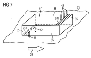
- FIG. 7 A third embodiment of the inventive gas turbine combustion system is shown in Figure 7 which schematically shows a perspective view onto a section of a combustor wall 25 and a resonator 27.
- Features of the third embodiment which do not differ from features of the first and second embodiments are denominated with the same reference numerals as in the first and second embodiments and will not be explained again.
- the third embodiment differs from the modification of the second embodiment shown in Figure 6 in that a feed slot 247 is present which although sharing the same orientation with the neck slot 137 is not aligned with the neck slot 137. Instead, the feed slot 247 is located close to a second peripheral wall 35 which lies in opposing relationship to the peripheral wall 35 to which the neck slot 137 lies close to.
- cooling air 43 which enters the resonator volume 31 through the feed slot 147 flows through the resonator volume along the combustor wall 25 to the neck slot 137. While flowing along the combustor wall 25 the cooling air can gather heat and hence cool the combustor wall 25 before purging the neck slot 137.
- the resonator wall lying opposite to the resonator wall 33 containing the feed opening or feed slot, respectively can be either formed by the combustor wall 25, as shown in Figure 3 , or by an inherent wall 49 of the resonator, as shown in Figure 4 .
- the invention as has been described with respect to the embodiments improves a gas turbine combustion system including resonators in that a neck slot can more easily be masked prior to coating than an array of small neck holes.
- a coating can easily protect the liner material or wall material against overheating in the region where resonators are mounted. Cooling air can be directed to the neck slot leading to efficient purging of the slot with air and efficient cooling of the remaining liner material or wall material which could not be covered by coating due to masking.
Landscapes
- Engineering & Computer Science (AREA)
- Chemical & Material Sciences (AREA)
- Combustion & Propulsion (AREA)
- Mechanical Engineering (AREA)
- General Engineering & Computer Science (AREA)
- Turbine Rotor Nozzle Sealing (AREA)
Description
- The present invention relates to a gas turbine combustion system, in particular to a gas turbine combustion system comprising a resonator. In addition, the invention relates to a gas turbine.
- Gas turbine combustion systems using lean premix combustion technology show a tendency towards self-excited acoustic oscillations. The reason for this phenomenon is the interaction of the heat release in the flame with pressure levels in the combustion system. At certain conditions pressure oscillations can be generated which can lead to acoustic noise in the combustor. At certain frequencies, amplification of such pressure oscillations may occur leading to very high acoustic pressure levels in the combustor necessciating engine shut down for avoiding damage to the combustor structure.
- Resonators are a common means for providing additional damping and detuning of pressure oscillations at the frequencies which are prone to be excited in gas turbine combustion systems. Particularly resonators avoiding high frequency dynamics (HFD) are often used in modern gas turbine combustion chambers.
DE 10 2006 040 760 A1 discloses a gas turbine combustion system with a resonator comprising several oval damping openings being oriented towards a hot gas flow path. Another combustion system comprising resonators is, for example, described inUS 6,530,221 B1 . The resonators described therein comprise an array of cooling air supply holes and an array of neck holes connecting the resonator volume to the combustion space of the combustion system where acoustic oscillations are to be damped. In order to prevent hot combustion gas from entering the neck holes these holes are purged with cooling air. However, resonators requiring cooling air may inhibit thermal barrier coating on the combustor liner in the region where resonators are installed. Therefore, they may reduce the life cycle of a combustor liner due to local overheating if not sufficient cooling air or thermal barrier coating of the combustor can be provided. In addition the array of neck holes requires high effort during the production process when it is masked for subsequent thermal barrier coating. With the small diameter of the holes used, masking must be done carefully since the frequency at which resonators are most effective is sensitive to the effective hole length influenced by the thermal barrier coating thickness. If the effort for masking within set tolerance limits is too high, it might even be inhibitive for coating. In this case, overheating of the combustor liner may occur since the pressure of the cooling air provided is generally high enough for purging the neck holes whilst the mass flow might not be sufficient for providing sufficient cooling of the structure. - It is therefore an objective of the present invention to provide an advantageous gas turbine combustion system comprising a resonator which allows for purging a neck opening with cooling air. It is a further objective of the present invention to provide an advantages gas turbine.
- The first objective is solved by a gas turbine combustion system as claimed in claim 1 and the second objective is solved by a gas turbine as claimed in claim 11. The depending claims contain further developments of the invention.
- An inventive gas turbine combustion system comprises a combustion system wall delimiting a flow path for hot and pressurised combustion gas and at least one resonator with a resonator volume delimited by resonators walls. One of the resonator walls is located adjacent to, or is formed by, a wall of the combustion system, called combustion system wall henceforth. The resonator comprises a neck opening being open towards the flow path and at least one cooling fluid supply opening being open towards a cooling fluid source. The neck opening is implemented in the form of a neck slot and a single neck slot is the only opening of the resonator towards the flow path.
- According to the invention, the array of resonator neck holes used in the state of the art combustion systems is replaced by a slot. The effective area of the neck slot is chosen depending on the frequency to be damped, the resonator volume and the resonator neck length which is given by the thickness of the combustion system wall including the acoustically relevant thermal barrier coating thickness plus, if applicable, the resonator wall being located adjacent to the combustion system wall, and the acoustic radiation effects at the inlet and the outlet of the neck. When coating the surrounding surface of the combustion system wall the neck slot can easily be masked as compared to an array of relatively small neck holes. Hence, the combustion system wall can more easily be protected by thermal barrier coatings in locations where resonators are provided than in the state of the art. Such areas which could not be covered by thermal barrier coating due to masking can be effectively cooled by the cooling fluid used for purging the slot since regions not covered by thermal barrier coating due to a masking lie adjacent to the slot.
- According to the invention there is only one single neck slot for each resonator, i. e. the neck slot of a resonator is the only opening of the respective resonator towards the flow path of the hot combustion gas.
- In addition to the neck opening, the at least one cooling fluid supply opening can be implemented as a slot, called supply slot in the following, too. Like the neck slot being the only opening of the resonator towards the flow path the supply slot may be the only opening of the resonator towards the cooling fluid supply.
- Independent of the implementation of the at least one cooling fluid supply opening said at least one opening is advantageously present in a resonator wall which is located in an opposing relationship to the resonator wall comprising the neck slot. In particular, the at least one cooling fluid supply opening may be aligned with the neck slot, for example by providing a single supply slot as a cooling fluid supply opening which is aligned with the neck slot, or by providing a number of cooling fluid supply holes as cooling fluid supply openings which are arranged along a line which is aligned with the neck slot. Hence, according to the mentioned development of the invention the array of cooling fluid supply holes used in the state of the art is replaced by a small number of holes, or a single slot, effectively providing purge air to the neck slot such that hot gas ingestion is avoided.
- According to a further development of the inventive gas turbine combustion system the resonator comprises at least one circumferential wall, and the neck slot is located close to and extending along the circumferential wall. The same may be true for a supply slot or a line of supply holes. Note that the resonator comprises one circumferential wall if it has a circular geometry, two circumferential walls if the resonator has an annular geometry, and three or more circumferential walls if the resonator has a polygonal geometry. According to the geometry, the slot or line may be a linear slot, a broken slot or line, or an arcuate slot or line.
- If the resonator comprises at least two circumferential walls, e.g. four circumferential walls so that it has a tetragonal shape, the neck slot may be located close to and extending along a first one of the circumferential walls and the at least one cooling fluid supply opening may be located close to and extending along a second one of the circumferential walls. The second one may, in particular, be located in an opposing relationship to the first circumferential wall. In this configuration, the cooling fluid needs to flow along the resonator wall located at the hot gas path side of the resonator to the neck slot so that this wall is cooled by the cooling fluid before the neck slot is purged.
- In the inventive combustion system the combustion system wall may particularly comprise a hot side which is directed towards the flow path and which is provided with a thermal barrier coating. By providing a thermal barrier coating overheating of the combustion system wall can be avoided, in particular if the cooling air in the resonator volume flows along the combustion system wall before purging the neck slot.
- An inventive gas turbine comprises an inventive combustion system. In such a gas turbine, exciting acoustic oscillations can be suppressed without reducing the lifetime of the combustion system wall at locations where resonators are present.
- Further features, properties and advantages of the present invention will be come clear from the following description of embodiments in conjunction with the accompanying drawings.
-
Fig. 1 shows a gas turbine in a highly schematic sectional view. -
Fig. 2 schematically shows a section of a first embodiment of the inventive gas turbine combustion system in a perspective view. -
Fig. 3 shows the embodiment ofFig. 1 in sectional view. -
Fig. 4 shows a modification of the first embodiment. -
Fig. 5 schematically shows a section of a second embodiment of the inventive gas turbine combustion system in a perspective view. -
Fig. 6 schematically shows a section of a modification of the second embodiment in a perspective view. -
Fig. 7 schematically shows a section of a third embodiment of the inventive gas turbine combustion system in a perspective view. -
Figure 1 shows, in a highly schematic view, a gas turbine engine 1 comprising acompressor section 3, a combustor section 5 and aturbine section 7. A rotor 9 extends through all sections and carries, in thecompressor section 3, rings of compressor blades 11 and, in theturbine section 7, rings ofturbine blades 13. Between neighbouring rings of compressor blades 11 and between neighbouring rings ofturbine blades 13, rings ofcompressor vanes 15 andturbine vanes 17, respectively, extend from ahousing 19 of the gas turbine engine 1 radially inwards towards the rotor 9. - The combustor section 5 is arranged between the
compressor section 3 and theturbine section 7. It comprises a combustion system with at least onecombustion chamber 8 to which one or more burners 6 are connected. The at least one burner 6 receives a gaseous or liquid fuel from a fuel supply system. In addition, the at least one burner 6 is in fluidic communication with thecompressor section 3 to receive compressed air. Thecombustion chamber 8 is in fluidic communication with theturbine section 7 to deliver hot and pressurized hot combustion gas resulting from a combustion of an fuel-air mixture in thecombustion chamber 8 to theturbine blades 13. - In operation of the gas turbine engine 1 air is taken in through an
air inlet 21 of thecompressor section 3. The air is compressed and, at the same time, led towards the combustor section 5 by the rotating compressor blades 11. In the combustor section 5 the air is mixed with a gaseous or liquid fuel and the mixture is burnt in the at least onecombustion chamber 8. The hot and pressurised combustion gas resulting from burning the fuel-air mixture is fed to theturbine section 7. On its way through theturbine section 7 the hot and pressurised gas transfers momentum to theturbine blades 13 while expanding and cooling, thereby imparting a rotational movement to the rotor 9 that drives the compressor and a consumer, e.g. a generator for producing electrical power or an industrial machine. The rings ofturbine vanes 17 function as nozzles for guiding the hot and pressurised combustion gas so as to optimise the momentum transfer to theturbine blades 13. Finally, the expanded and cooled combustion gas leaves theturbine section 7 through anexhaust 23. - The first embodiment of the gas turbine combustion system according to the invention is depicted in
Figures 2 and3 . WhileFigure 2 schematically shows a three-dimensional view onto a section of a combustor wall orliner 25 which is equipped with a resonator,figure 3 shows a sectional view through theresonator 27 and the combustor wall orliner 25. Note that although it will be referred to "combustor wall" 25 from now on throughout the embodiments the term "combustor wall" shall also include the meaning of "combustor liner". - In the present embodiment, the combustion system wall represented by the
combustor wall 25 limits a flow path for hot and pressurised combustion gas. The flow of the hot and pressurized combustion gas is indicated byarrow 29. Theresonator 27 is located adjacent to thecombustor wall 25 so that thecombustor wall 25 and an opposingresonator wall 33, together withcircumferential resonator walls 35 extending between thecombustor wall 25 and the opposingresonator wall 33, enclose aresonator volume 31. - A
slot 37 is present in thecombustor wall 25 connecting thecombustor volume 31 to the flow path for the hot andpressurized combustion gas 29. Theslot 37, which is located close to acircumferential wall 35 of theresonator 27, resembles a neck opening of the resonator being open towards the flow path for the hot and pressurized combustion gas. The neck length of the resonator neck provided by theslot 37 is given by the sum of the thicknesses of thecombustor wall 25 and athermal barrier coating 39 applied to the inside of the combustor wall, i. e. to the side of the combustor wall which faces the hot and pressurized combustion gas. By suitably choosing the length of the resonator neck together with the size of the resonator volume and the effective area of the neck slot the resonator can be tuned to a certain frequency to be damped. - In order to allow cooling air provided by the compressor to pass through the
resonator volume 31 and theneck slot 37 into the flow path of the hot and pressurizecombustion gas 27 for purging the neck slot 37 a number of feed holes 41 is present in aresonator wall 33 which is located in an opposing relationship to thecombustor wall 25. The feed holes 41 are arranged along a line which is aligned with theneck slot 37 so that coolingair 43 entering theresonator volume 31 through the feed holes 41 can unhindered pass thevolume 31 to purge theneck slot 37, as indicated byarrows 45. By allowing cooling air to effectively purge theneck slot 37 ingestion of hot and pressurized combustion gas into theresonator volume 31 can be effectively avoided. - Alternatively to a line of feed holes 41 a
feed slot 47 could be provided in theresonator wall 33 as it is show inFigure 4 , which depicts a modification of the embodiment shown inFigures 2 and3 in a sectional view. In addition to the modification given by thefeed slot 47 as a cooling fluid supply opening instead of the feed holes 41 theresonator 27 also comprises afurther resonator wall 49 which is arranged adjacent to thecombustor wall 25 and, thus, in opposing relationship to theresonator wall 33 containing thefeed slot 47. Hence, theneck slot 37 not only extends through thecombustor wall 25 and thethermal barrier coating 39 but also through thefurther combustor wall 49, which increases the neck length provided by theneck slot 37. - A second embodiment of the inventive gas turbine combustion system is schematically shown in
Figure 5 in a perspective view. Those features of the second embodiment which do not differ from the first embodiment are denominated by the same reference numerals as in the first embodiment and will not be explained again. - The difference of the second embodiment with respect to the first embodiment lies in the direction the
neck slot 137 and the line of feed holes 141 is oriented with respect to the flow direction of the hot andpressurized combustion gas 29. While theneck slot 37 and the line of feed holes 41 of the first embodiment are oriented in parallel to the flow direction of the hot and pressurized combustion gas the orientation of theneck slot 137 and the orientation of the line of feed holes 141 are perpendicular to the flow direction of the hot andpressurized combustion gas 29 in the present embodiment. Like in the first embodiment, theneck slot 137 and the feed holes 141 are aligned with each other and are located close to acircumferential resonator wall 35. - A modification of the second embodiment is shown in
Figure 6 . The modification lies in that the line offeed openings 141 is replaced by afeed slot 147 which is aligned with theneck slot 137. - A third embodiment of the inventive gas turbine combustion system is shown in
Figure 7 which schematically shows a perspective view onto a section of acombustor wall 25 and aresonator 27. Features of the third embodiment which do not differ from features of the first and second embodiments are denominated with the same reference numerals as in the first and second embodiments and will not be explained again. - The third embodiment differs from the modification of the second embodiment shown in
Figure 6 in that afeed slot 247 is present which although sharing the same orientation with theneck slot 137 is not aligned with theneck slot 137. Instead, thefeed slot 247 is located close to a secondperipheral wall 35 which lies in opposing relationship to theperipheral wall 35 to which theneck slot 137 lies close to. This means that coolingair 43 which enters theresonator volume 31 through thefeed slot 147 flows through the resonator volume along thecombustor wall 25 to theneck slot 137. While flowing along thecombustor wall 25 the cooling air can gather heat and hence cool thecombustor wall 25 before purging theneck slot 137. - Note, that in all embodiments the resonator wall lying opposite to the
resonator wall 33 containing the feed opening or feed slot, respectively, can be either formed by thecombustor wall 25, as shown inFigure 3 , or by aninherent wall 49 of the resonator, as shown inFigure 4 . - The invention as has been described with respect to the embodiments improves a gas turbine combustion system including resonators in that a neck slot can more easily be masked prior to coating than an array of small neck holes. Hence, a coating can easily protect the liner material or wall material against overheating in the region where resonators are mounted. Cooling air can be directed to the neck slot leading to efficient purging of the slot with air and efficient cooling of the remaining liner material or wall material which could not be covered by coating due to masking.
Claims (11)
- A gas turbine combustion system comprising a combustion system wall (25) delimiting a flow path for hot and pressurized combustion gas (29) and at least one resonator (27) with a resonator volume (31) delimited by resonator walls (25, 33, 35, 49), where one of the resonator walls (25, 49) is located adjacent to or is formed by the combustion system wall (25), the resonator (27) comprising a neck opening (37, 137) being open towards the flow path and at least one cooling fluid supply opening (41, 47, 141, 147, 247) being open towards a cooling fluid source, where the neck opening is implemented in the form of a neck slot (37, 137)
characterised in that
a single neck slot (37, 137) is the only opening of the resonator (27) towards the flow path. - The gas turbine combustion system as claimed in claim 1,
characterised in that
the at least one cooling fluid supply opening is implemented in the form of a supply slot (47, 147, 247). - The gas turbine combustion system as claimed in claim 2,
characterised in that
there is a single supply slot (47, 147, 247) as the only opening of the resonator towards the cooling fluid supply. - The gas turbine combustion system as claimed in any of the claims 1 to 3,
characterised in that
the at least one cooling fluid supply opening (41, 47, 141, 147, 247) is present in a resonator wall (33) which is located in an opposing relationship to the resonator wall (25, 49) comprising the neck slot (37, 137). - The gas turbine combustion system as claimed in claim 4,
characterised in that
the at least one cooling fluid supply opening (41, 47, 141, 147) is aligned with the neck slot (37, 137). - The gas turbine combustion system as claimed in claim 4,
characterised in that
the at least one cooling fluid supply opening (41, 141) is implemented as a number of cooling fluid supply holes (41, 141) which are located in the resonator wall (33) opposing the resonator wall with the neck slot (37, 137) and which are arranged along a line which is aligned with the neck slot (37, 137). - The gas turbine combustion system as claimed in any of the claims 1 to 6,
characterised in that
the resonator (27) comprises at least one circumferential wall (35) and the neck slot (37, 137) is located close to and extending along a circumferential wall (35). - The gas turbine combustion system as claimed in claim 7,
characterised in that
the resonator (27) comprises at least two circumferential walls (35), the neck slot (37, 137) is located close to and extending along a first circumferential wall and the at least one cooling fluid supply opening (41, 47, 141, 147, 247) is located close to and extending along a second circumferential wall (35'). - The gas turbine combustion system as claimed in claim 8,
characterised in that
the second circumferential wall (35') is located in an opposing relationship to the first circumferential wall 35. - The gas turbine combustion system as claimed in any of the claims 1 to 8,
characterised in that
the combustion system wall (25) comprises a hot side which is directed towards the flow path and which comprises a thermal barrier coating 39. - A gas turbine comprising a combustion system as claimed in any of the claims 1 to 10.
Applications Claiming Priority (2)
| Application Number | Priority Date | Filing Date | Title |
|---|---|---|---|
| US12/407,133 US20100236245A1 (en) | 2009-03-19 | 2009-03-19 | Gas Turbine Combustion System |
| PCT/EP2010/052542 WO2010105898A1 (en) | 2009-03-19 | 2010-03-01 | Gas turbine combustion system |
Publications (2)
| Publication Number | Publication Date |
|---|---|
| EP2409084A1 EP2409084A1 (en) | 2012-01-25 |
| EP2409084B1 true EP2409084B1 (en) | 2014-04-30 |
Family
ID=42224050
Family Applications (1)
| Application Number | Title | Priority Date | Filing Date |
|---|---|---|---|
| EP10707500.4A Not-in-force EP2409084B1 (en) | 2009-03-19 | 2010-03-01 | Gas turbine combustion system |
Country Status (6)
| Country | Link |
|---|---|
| US (1) | US20100236245A1 (en) |
| EP (1) | EP2409084B1 (en) |
| JP (1) | JP5377747B2 (en) |
| CN (1) | CN102356278B (en) |
| RU (1) | RU2507451C2 (en) |
| WO (1) | WO2010105898A1 (en) |
Families Citing this family (15)
| Publication number | Priority date | Publication date | Assignee | Title |
|---|---|---|---|---|
| ES2400267T3 (en) * | 2009-08-31 | 2013-04-08 | Alstom Technology Ltd | Combustion device of a gas turbine |
| US20120137690A1 (en) * | 2010-12-03 | 2012-06-07 | General Electric Company | Wide frequency response tunable resonator |
| CA2887454A1 (en) * | 2012-10-24 | 2014-05-01 | Alstom Technology Ltd. | Sequential combustion with dilution gas mixer |
| JP2016516975A (en) * | 2013-04-25 | 2016-06-09 | ゼネラル エレクトリック テクノロジー ゲゼルシャフト ミット ベシュレンクテル ハフツングGeneral Electric Technology GmbH | Multistage combustion with dilution gas |
| EP2816289B1 (en) * | 2013-05-24 | 2020-10-07 | Ansaldo Energia IP UK Limited | Damper for gas turbine |
| US9410484B2 (en) * | 2013-07-19 | 2016-08-09 | Siemens Aktiengesellschaft | Cooling chamber for upstream weld of damping resonator on turbine component |
| EP2837782A1 (en) | 2013-08-14 | 2015-02-18 | Alstom Technology Ltd | Damper for combustion oscillation damping in a gas turbine |
| JP6563004B2 (en) * | 2014-09-05 | 2019-08-28 | シーメンス アクチエンゲゼルシヤフトSiemens Aktiengesellschaft | An acoustic damping system for a gas turbine engine combustor. |
| WO2016036380A1 (en) * | 2014-09-05 | 2016-03-10 | Siemens Aktiengesellschaft | Acoustic damping system for a combustor of a gas turbine engine |
| WO2016039725A1 (en) * | 2014-09-09 | 2016-03-17 | Siemens Aktiengesellschaft | Acoustic damping system for a combustor of a gas turbine engine |
| CN105423341B (en) * | 2015-12-30 | 2017-12-15 | 哈尔滨广瀚燃气轮机有限公司 | There is the premixed low emission gas turbine combustion chamber of flame on duty |
| RU2706211C2 (en) * | 2016-01-25 | 2019-11-14 | Ансалдо Энерджиа Свитзерлэнд Аг | Cooled wall of turbine component and cooling method of this wall |
| CN109563994B (en) | 2016-07-25 | 2020-12-01 | 西门子股份公司 | Gas Turbine Engine with Resonator Ring |
| US10539066B1 (en) * | 2018-11-21 | 2020-01-21 | GM Global Technology Operations LLC | Vehicle charge air cooler with an integrated resonator |
| GB2632877A (en) * | 2023-08-14 | 2025-02-26 | Siemens Energy Global Gmbh & Co Kg | Combustor with resonator for gas turbine engine |
Family Cites Families (25)
| Publication number | Priority date | Publication date | Assignee | Title |
|---|---|---|---|---|
| US4100993A (en) * | 1976-04-15 | 1978-07-18 | United Technologies Corporation | Acoustic liner |
| US4135603A (en) * | 1976-08-19 | 1979-01-23 | United Technologies Corporation | Sound suppressor liners |
| FR2685386B1 (en) * | 1991-12-20 | 1994-03-25 | Propulsion Ste Europeenne | SYSTEM FOR DAMPING HIGH FREQUENCY COMBUSTION INSTABILITIES IN A COMBUSTION CHAMBER. |
| US5276291A (en) * | 1992-07-10 | 1994-01-04 | Norris Thomas R | Acoustic muffler for high volume fluid flow utilizing Heimholtz resonators with low flow resistance path |
| US5542246A (en) * | 1994-12-15 | 1996-08-06 | United Technologies Corporation | Bulkhead cooling fairing |
| JP3756994B2 (en) * | 1995-07-11 | 2006-03-22 | 株式会社日立製作所 | Gas turbine combustor, gas turbine and components thereof |
| EP0974788B1 (en) * | 1998-07-23 | 2014-11-26 | Alstom Technology Ltd | Device for directed noise attenuation in a turbomachine |
| DE59810347D1 (en) * | 1998-09-10 | 2004-01-15 | Alstom Switzerland Ltd | Vibration damping in combustion chambers |
| US6379110B1 (en) * | 1999-02-25 | 2002-04-30 | United Technologies Corporation | Passively driven acoustic jet controlling boundary layers |
| US6350221B1 (en) * | 1999-08-13 | 2002-02-26 | Mark A. Krull | Convertible exercise apparatus with body supporting element |
| US6530221B1 (en) * | 2000-09-21 | 2003-03-11 | Siemens Westinghouse Power Corporation | Modular resonators for suppressing combustion instabilities in gas turbine power plants |
| GB0111788D0 (en) * | 2001-05-15 | 2001-07-04 | Rolls Royce Plc | A combustion chamber |
| EP1423645B1 (en) * | 2001-09-07 | 2008-10-08 | Alstom Technology Ltd | Damping arrangement for reducing combustion chamber pulsations in a gas turbine system |
| RU2212589C1 (en) * | 2002-06-28 | 2003-09-20 | Козырев Александр Валентинович | Heat engine combustion chamber |
| RU2219439C1 (en) * | 2002-09-03 | 2003-12-20 | Андреев Анатолий Васильевич | Combustion chamber |
| WO2004051063A1 (en) * | 2002-12-02 | 2004-06-17 | Mitsubishi Heavy Industries, Ltd. | Gas turbine combustor, and gas turbine with the combustor |
| JP2005076982A (en) * | 2003-08-29 | 2005-03-24 | Mitsubishi Heavy Ind Ltd | Gas turbine combustor |
| US7272931B2 (en) * | 2003-09-16 | 2007-09-25 | General Electric Company | Method and apparatus to decrease combustor acoustics |
| US7219498B2 (en) * | 2004-09-10 | 2007-05-22 | Honeywell International, Inc. | Waffled impingement effusion method |
| GB0425794D0 (en) * | 2004-11-24 | 2004-12-22 | Rolls Royce Plc | Acoustic damper |
| GB0610800D0 (en) * | 2006-06-01 | 2006-07-12 | Rolls Royce Plc | Combustion chamber for a gas turbine engine |
| DE102006040760A1 (en) * | 2006-08-31 | 2008-03-06 | Rolls-Royce Deutschland Ltd & Co Kg | Lean-burning gas turbine combustion chamber wall, has Inflow holes formed perpendicularly over chamber wall, and damping openings formed by shingle, where shingle is spaced apart from chamber wall by using side part |
| JP2008121961A (en) * | 2006-11-10 | 2008-05-29 | Mitsubishi Heavy Ind Ltd | Acoustic liner for gas turbine combustor |
| GB0713526D0 (en) * | 2007-07-12 | 2007-08-22 | Rolls Royce Plc | An acoustic panel |
| US8061141B2 (en) * | 2007-09-27 | 2011-11-22 | Siemens Energy, Inc. | Combustor assembly including one or more resonator assemblies and process for forming same |
-
2009
- 2009-03-19 US US12/407,133 patent/US20100236245A1/en not_active Abandoned
-
2010
- 2010-03-01 EP EP10707500.4A patent/EP2409084B1/en not_active Not-in-force
- 2010-03-01 CN CN201080012150.4A patent/CN102356278B/en not_active Expired - Fee Related
- 2010-03-01 WO PCT/EP2010/052542 patent/WO2010105898A1/en not_active Ceased
- 2010-03-01 JP JP2012500172A patent/JP5377747B2/en not_active Expired - Fee Related
- 2010-03-01 RU RU2011142145/06A patent/RU2507451C2/en not_active IP Right Cessation
Also Published As
| Publication number | Publication date |
|---|---|
| RU2011142145A (en) | 2013-04-27 |
| JP2012520982A (en) | 2012-09-10 |
| RU2507451C2 (en) | 2014-02-20 |
| EP2409084A1 (en) | 2012-01-25 |
| US20100236245A1 (en) | 2010-09-23 |
| CN102356278B (en) | 2014-04-09 |
| WO2010105898A1 (en) | 2010-09-23 |
| JP5377747B2 (en) | 2013-12-25 |
| CN102356278A (en) | 2012-02-15 |
Similar Documents
| Publication | Publication Date | Title |
|---|---|---|
| US20100236245A1 (en) | Gas Turbine Combustion System | |
| US9506654B2 (en) | System and method for reducing combustion dynamics in a combustor | |
| EP1666795B1 (en) | Acoustic damper | |
| JP5674336B2 (en) | Combustor can flow control device | |
| JP5291790B2 (en) | Combustor and gas turbine provided with the same | |
| EP1424469B1 (en) | Combustor sealing arrangement | |
| EP1669670B1 (en) | Helmholtz resonator for a combustion chamber for a gas turbine engine | |
| US8061141B2 (en) | Combustor assembly including one or more resonator assemblies and process for forming same | |
| EP2208933B1 (en) | Combustor assembly and cap for a turbine engine | |
| JP5112926B2 (en) | System for reducing combustor dynamics | |
| CA2433402C (en) | Combustor for gas turbine | |
| JP5349605B2 (en) | Burner insertion device and gas turbine for gas turbine combustion chamber | |
| US9249734B2 (en) | Combustor | |
| US10415831B2 (en) | Combustor assembly with mounted auxiliary component | |
| KR20100061538A (en) | Secondary fuel delivery system | |
| JP2018123825A (en) | System and apparatus for inner cap and extended resonance tube of gas turbine combustor | |
| US7065971B2 (en) | Device for efficient usage of cooling air for acoustic damping of combustion chamber pulsations | |
| EP4028694B1 (en) | System for acoustic dampers with multiple volumes in a combustion chamber front panel | |
| EP2745054B1 (en) | Combustion arrangement and turbine comprising a damping facility | |
| EP3845810B1 (en) | Supporting device for a heat-insulating tiles of a combustion chamber of a gas turbine assembly for power plants and a gas turbine assembly | |
| JP6506497B2 (en) | System and method for separating fluid | |
| US20130067923A1 (en) | Combustor and method for conditioning flow through a combustor |
Legal Events
| Date | Code | Title | Description |
|---|---|---|---|
| PUAI | Public reference made under article 153(3) epc to a published international application that has entered the european phase |
Free format text: ORIGINAL CODE: 0009012 |
|
| 17P | Request for examination filed |
Effective date: 20110915 |
|
| AK | Designated contracting states |
Kind code of ref document: A1 Designated state(s): AT BE BG CH CY CZ DE DK EE ES FI FR GB GR HR HU IE IS IT LI LT LU LV MC MK MT NL NO PL PT RO SE SI SK SM TR |
|
| DAX | Request for extension of the european patent (deleted) | ||
| RAP1 | Party data changed (applicant data changed or rights of an application transferred) |
Owner name: SIEMENS AKTIENGESELLSCHAFT |
|
| GRAP | Despatch of communication of intention to grant a patent |
Free format text: ORIGINAL CODE: EPIDOSNIGR1 |
|
| INTG | Intention to grant announced |
Effective date: 20131022 |
|
| GRAS | Grant fee paid |
Free format text: ORIGINAL CODE: EPIDOSNIGR3 |
|
| GRAA | (expected) grant |
Free format text: ORIGINAL CODE: 0009210 |
|
| AK | Designated contracting states |
Kind code of ref document: B1 Designated state(s): AT BE BG CH CY CZ DE DK EE ES FI FR GB GR HR HU IE IS IT LI LT LU LV MC MK MT NL NO PL PT RO SE SI SK SM TR |
|
| REG | Reference to a national code |
Ref country code: GB Ref legal event code: FG4D Ref country code: CH Ref legal event code: EP |
|
| REG | Reference to a national code |
Ref country code: AT Ref legal event code: REF Ref document number: 665400 Country of ref document: AT Kind code of ref document: T Effective date: 20140515 |
|
| REG | Reference to a national code |
Ref country code: IE Ref legal event code: FG4D |
|
| REG | Reference to a national code |
Ref country code: DE Ref legal event code: R096 Ref document number: 602010015562 Country of ref document: DE Effective date: 20140612 |
|
| REG | Reference to a national code |
Ref country code: CH Ref legal event code: NV Representative=s name: SIEMENS SCHWEIZ AG, CH |
|
| REG | Reference to a national code |
Ref country code: SE Ref legal event code: TRGR |
|
| REG | Reference to a national code |
Ref country code: AT Ref legal event code: MK05 Ref document number: 665400 Country of ref document: AT Kind code of ref document: T Effective date: 20140430 |
|
| REG | Reference to a national code |
Ref country code: LT Ref legal event code: MG4D |
|
| REG | Reference to a national code |
Ref country code: NL Ref legal event code: VDEP Effective date: 20140430 |
|
| PG25 | Lapsed in a contracting state [announced via postgrant information from national office to epo] |
Ref country code: IS Free format text: LAPSE BECAUSE OF FAILURE TO SUBMIT A TRANSLATION OF THE DESCRIPTION OR TO PAY THE FEE WITHIN THE PRESCRIBED TIME-LIMIT Effective date: 20140830 Ref country code: LT Free format text: LAPSE BECAUSE OF FAILURE TO SUBMIT A TRANSLATION OF THE DESCRIPTION OR TO PAY THE FEE WITHIN THE PRESCRIBED TIME-LIMIT Effective date: 20140430 Ref country code: BG Free format text: LAPSE BECAUSE OF FAILURE TO SUBMIT A TRANSLATION OF THE DESCRIPTION OR TO PAY THE FEE WITHIN THE PRESCRIBED TIME-LIMIT Effective date: 20140730 Ref country code: NO Free format text: LAPSE BECAUSE OF FAILURE TO SUBMIT A TRANSLATION OF THE DESCRIPTION OR TO PAY THE FEE WITHIN THE PRESCRIBED TIME-LIMIT Effective date: 20140730 Ref country code: GR Free format text: LAPSE BECAUSE OF FAILURE TO SUBMIT A TRANSLATION OF THE DESCRIPTION OR TO PAY THE FEE WITHIN THE PRESCRIBED TIME-LIMIT Effective date: 20140731 Ref country code: FI Free format text: LAPSE BECAUSE OF FAILURE TO SUBMIT A TRANSLATION OF THE DESCRIPTION OR TO PAY THE FEE WITHIN THE PRESCRIBED TIME-LIMIT Effective date: 20140430 Ref country code: NL Free format text: LAPSE BECAUSE OF FAILURE TO SUBMIT A TRANSLATION OF THE DESCRIPTION OR TO PAY THE FEE WITHIN THE PRESCRIBED TIME-LIMIT Effective date: 20140430 Ref country code: CY Free format text: LAPSE BECAUSE OF FAILURE TO SUBMIT A TRANSLATION OF THE DESCRIPTION OR TO PAY THE FEE WITHIN THE PRESCRIBED TIME-LIMIT Effective date: 20140430 |
|
| PG25 | Lapsed in a contracting state [announced via postgrant information from national office to epo] |
Ref country code: PL Free format text: LAPSE BECAUSE OF FAILURE TO SUBMIT A TRANSLATION OF THE DESCRIPTION OR TO PAY THE FEE WITHIN THE PRESCRIBED TIME-LIMIT Effective date: 20140430 Ref country code: AT Free format text: LAPSE BECAUSE OF FAILURE TO SUBMIT A TRANSLATION OF THE DESCRIPTION OR TO PAY THE FEE WITHIN THE PRESCRIBED TIME-LIMIT Effective date: 20140430 Ref country code: ES Free format text: LAPSE BECAUSE OF FAILURE TO SUBMIT A TRANSLATION OF THE DESCRIPTION OR TO PAY THE FEE WITHIN THE PRESCRIBED TIME-LIMIT Effective date: 20140430 Ref country code: LV Free format text: LAPSE BECAUSE OF FAILURE TO SUBMIT A TRANSLATION OF THE DESCRIPTION OR TO PAY THE FEE WITHIN THE PRESCRIBED TIME-LIMIT Effective date: 20140430 Ref country code: HR Free format text: LAPSE BECAUSE OF FAILURE TO SUBMIT A TRANSLATION OF THE DESCRIPTION OR TO PAY THE FEE WITHIN THE PRESCRIBED TIME-LIMIT Effective date: 20140430 |
|
| PG25 | Lapsed in a contracting state [announced via postgrant information from national office to epo] |
Ref country code: PT Free format text: LAPSE BECAUSE OF FAILURE TO SUBMIT A TRANSLATION OF THE DESCRIPTION OR TO PAY THE FEE WITHIN THE PRESCRIBED TIME-LIMIT Effective date: 20140901 |
|
| PG25 | Lapsed in a contracting state [announced via postgrant information from national office to epo] |
Ref country code: DK Free format text: LAPSE BECAUSE OF FAILURE TO SUBMIT A TRANSLATION OF THE DESCRIPTION OR TO PAY THE FEE WITHIN THE PRESCRIBED TIME-LIMIT Effective date: 20140430 Ref country code: EE Free format text: LAPSE BECAUSE OF FAILURE TO SUBMIT A TRANSLATION OF THE DESCRIPTION OR TO PAY THE FEE WITHIN THE PRESCRIBED TIME-LIMIT Effective date: 20140430 Ref country code: SK Free format text: LAPSE BECAUSE OF FAILURE TO SUBMIT A TRANSLATION OF THE DESCRIPTION OR TO PAY THE FEE WITHIN THE PRESCRIBED TIME-LIMIT Effective date: 20140430 Ref country code: CZ Free format text: LAPSE BECAUSE OF FAILURE TO SUBMIT A TRANSLATION OF THE DESCRIPTION OR TO PAY THE FEE WITHIN THE PRESCRIBED TIME-LIMIT Effective date: 20140430 Ref country code: RO Free format text: LAPSE BECAUSE OF FAILURE TO SUBMIT A TRANSLATION OF THE DESCRIPTION OR TO PAY THE FEE WITHIN THE PRESCRIBED TIME-LIMIT Effective date: 20140430 Ref country code: BE Free format text: LAPSE BECAUSE OF FAILURE TO SUBMIT A TRANSLATION OF THE DESCRIPTION OR TO PAY THE FEE WITHIN THE PRESCRIBED TIME-LIMIT Effective date: 20140430 |
|
| REG | Reference to a national code |
Ref country code: DE Ref legal event code: R097 Ref document number: 602010015562 Country of ref document: DE |
|
| PLBE | No opposition filed within time limit |
Free format text: ORIGINAL CODE: 0009261 |
|
| STAA | Information on the status of an ep patent application or granted ep patent |
Free format text: STATUS: NO OPPOSITION FILED WITHIN TIME LIMIT |
|
| 26N | No opposition filed |
Effective date: 20150202 |
|
| REG | Reference to a national code |
Ref country code: DE Ref legal event code: R097 Ref document number: 602010015562 Country of ref document: DE Effective date: 20150202 |
|
| PG25 | Lapsed in a contracting state [announced via postgrant information from national office to epo] |
Ref country code: SI Free format text: LAPSE BECAUSE OF FAILURE TO SUBMIT A TRANSLATION OF THE DESCRIPTION OR TO PAY THE FEE WITHIN THE PRESCRIBED TIME-LIMIT Effective date: 20140430 |
|
| PGFP | Annual fee paid to national office [announced via postgrant information from national office to epo] |
Ref country code: DE Payment date: 20150513 Year of fee payment: 6 Ref country code: CH Payment date: 20150602 Year of fee payment: 6 |
|
| PG25 | Lapsed in a contracting state [announced via postgrant information from national office to epo] |
Ref country code: MC Free format text: LAPSE BECAUSE OF FAILURE TO SUBMIT A TRANSLATION OF THE DESCRIPTION OR TO PAY THE FEE WITHIN THE PRESCRIBED TIME-LIMIT Effective date: 20140430 Ref country code: LU Free format text: LAPSE BECAUSE OF FAILURE TO SUBMIT A TRANSLATION OF THE DESCRIPTION OR TO PAY THE FEE WITHIN THE PRESCRIBED TIME-LIMIT Effective date: 20150301 |
|
| REG | Reference to a national code |
Ref country code: IE Ref legal event code: MM4A |
|
| PG25 | Lapsed in a contracting state [announced via postgrant information from national office to epo] |
Ref country code: IE Free format text: LAPSE BECAUSE OF NON-PAYMENT OF DUE FEES Effective date: 20150301 |
|
| REG | Reference to a national code |
Ref country code: FR Ref legal event code: PLFP Year of fee payment: 7 |
|
| PGFP | Annual fee paid to national office [announced via postgrant information from national office to epo] |
Ref country code: GB Payment date: 20160310 Year of fee payment: 7 Ref country code: FR Payment date: 20160311 Year of fee payment: 7 Ref country code: SE Payment date: 20160307 Year of fee payment: 7 |
|
| PGFP | Annual fee paid to national office [announced via postgrant information from national office to epo] |
Ref country code: IT Payment date: 20160329 Year of fee payment: 7 |
|
| REG | Reference to a national code |
Ref country code: DE Ref legal event code: R119 Ref document number: 602010015562 Country of ref document: DE |
|
| REG | Reference to a national code |
Ref country code: CH Ref legal event code: PL |
|
| PG25 | Lapsed in a contracting state [announced via postgrant information from national office to epo] |
Ref country code: MT Free format text: LAPSE BECAUSE OF FAILURE TO SUBMIT A TRANSLATION OF THE DESCRIPTION OR TO PAY THE FEE WITHIN THE PRESCRIBED TIME-LIMIT Effective date: 20140430 |
|
| PG25 | Lapsed in a contracting state [announced via postgrant information from national office to epo] |
Ref country code: LI Free format text: LAPSE BECAUSE OF NON-PAYMENT OF DUE FEES Effective date: 20160331 Ref country code: CH Free format text: LAPSE BECAUSE OF NON-PAYMENT OF DUE FEES Effective date: 20160331 Ref country code: DE Free format text: LAPSE BECAUSE OF NON-PAYMENT OF DUE FEES Effective date: 20161001 |
|
| PG25 | Lapsed in a contracting state [announced via postgrant information from national office to epo] |
Ref country code: HU Free format text: LAPSE BECAUSE OF FAILURE TO SUBMIT A TRANSLATION OF THE DESCRIPTION OR TO PAY THE FEE WITHIN THE PRESCRIBED TIME-LIMIT; INVALID AB INITIO Effective date: 20100301 Ref country code: SM Free format text: LAPSE BECAUSE OF FAILURE TO SUBMIT A TRANSLATION OF THE DESCRIPTION OR TO PAY THE FEE WITHIN THE PRESCRIBED TIME-LIMIT Effective date: 20140430 |
|
| PG25 | Lapsed in a contracting state [announced via postgrant information from national office to epo] |
Ref country code: TR Free format text: LAPSE BECAUSE OF FAILURE TO SUBMIT A TRANSLATION OF THE DESCRIPTION OR TO PAY THE FEE WITHIN THE PRESCRIBED TIME-LIMIT Effective date: 20140430 |
|
| REG | Reference to a national code |
Ref country code: SE Ref legal event code: EUG |
|
| GBPC | Gb: european patent ceased through non-payment of renewal fee |
Effective date: 20170301 |
|
| PG25 | Lapsed in a contracting state [announced via postgrant information from national office to epo] |
Ref country code: SE Free format text: LAPSE BECAUSE OF NON-PAYMENT OF DUE FEES Effective date: 20170302 |
|
| REG | Reference to a national code |
Ref country code: FR Ref legal event code: ST Effective date: 20171130 |
|
| PG25 | Lapsed in a contracting state [announced via postgrant information from national office to epo] |
Ref country code: FR Free format text: LAPSE BECAUSE OF NON-PAYMENT OF DUE FEES Effective date: 20170331 |
|
| PG25 | Lapsed in a contracting state [announced via postgrant information from national office to epo] |
Ref country code: IT Free format text: LAPSE BECAUSE OF NON-PAYMENT OF DUE FEES Effective date: 20170301 Ref country code: GB Free format text: LAPSE BECAUSE OF NON-PAYMENT OF DUE FEES Effective date: 20170301 |
|
| PG25 | Lapsed in a contracting state [announced via postgrant information from national office to epo] |
Ref country code: MK Free format text: LAPSE BECAUSE OF FAILURE TO SUBMIT A TRANSLATION OF THE DESCRIPTION OR TO PAY THE FEE WITHIN THE PRESCRIBED TIME-LIMIT Effective date: 20140430 |