EP2408962B1 - Arrangement, system and method for treatment of cellulose pulp - Google Patents
Arrangement, system and method for treatment of cellulose pulp Download PDFInfo
- Publication number
- EP2408962B1 EP2408962B1 EP10753767.2A EP10753767A EP2408962B1 EP 2408962 B1 EP2408962 B1 EP 2408962B1 EP 10753767 A EP10753767 A EP 10753767A EP 2408962 B1 EP2408962 B1 EP 2408962B1
- Authority
- EP
- European Patent Office
- Prior art keywords
- screening
- arrangement
- pulp
- inlet
- accept
- Prior art date
- Legal status (The legal status is an assumption and is not a legal conclusion. Google has not performed a legal analysis and makes no representation as to the accuracy of the status listed.)
- Active
Links
Images



Classifications
-
- D—TEXTILES; PAPER
- D21—PAPER-MAKING; PRODUCTION OF CELLULOSE
- D21D—TREATMENT OF THE MATERIALS BEFORE PASSING TO THE PAPER-MAKING MACHINE
- D21D5/00—Purification of the pulp suspension by mechanical means; Apparatus therefor
- D21D5/02—Straining or screening the pulp
- D21D5/023—Stationary screen-drums
- D21D5/026—Stationary screen-drums with rotating cleaning foils
-
- D—TEXTILES; PAPER
- D21—PAPER-MAKING; PRODUCTION OF CELLULOSE
- D21D—TREATMENT OF THE MATERIALS BEFORE PASSING TO THE PAPER-MAKING MACHINE
- D21D5/00—Purification of the pulp suspension by mechanical means; Apparatus therefor
- D21D5/02—Straining or screening the pulp
Definitions
- the present invention relates to treatment of cellulose pulp and in particular to a screening arrangement for cellulose pulp and a system and a method for screening of cellulose pulp.
- Screening refers to an operation in which fibers of a pulp suspension pass through a perforated plate with holes or slots, while the impurities are retained.
- the fraction of pulp passing the plate is referred to as the accept fraction or simply the accept.
- the fraction of pulp not passing through the openings of the plate is referred to as the reject fraction or simply the reject.
- the pulp fraction fed to the perforated plate is referred to as the inject fraction or simply the inject.
- An inject can thus be said to be a pulp flow about to be divided into an accept and a reject.
- slots for separation may be created in other ways, e.g. through forming a screen basket of longitudinal bars.
- the accept portion from the screening stage is passed to the next processing step while the reject portion is passed to a subsequent screening stage, in order to be screened again. In order to minimize fiber losses, the accept from the subsequent screening stage is then returned to the inject of the preceding screening stage. In that way, most of the "good" fibers are recovered.
- One commonly used screening apparatus is a so-called combi-screen, meaning that two or several screening stages are combined within the same screen housing.
- An example of such an apparatus is disclosed in EP 1 165 882 , where a first screening means is located at least partly within a second screening means.
- the screening apparatus comprises a screen housing with an upper chamber highest up in the screen housing, a rotor means, which housing is rotary about a rotor shaft, and at least two coaxially arranged screen means.
- a first tubular screen means divides the interior of the screen housing in radial direction into a first screen chamber located outside the first screen means with an outer defining surface, and a first accept chamber located inside the first screen means.
- a second tubular screen means divides the interior of the screen housing, so that a second screen chamber is formed between the second screen means and an inner defining surface.
- the first screen means has a smaller diameter than the second screen means and at least partially is located inside the second screen means.
- the screening apparatus further comprises an inlet means for fiber suspension to the screening apparatus, at least one reject outlet for reject from the screening apparatus, and at least one accept outlet means for accept from the screening apparatus.
- Combi-screens have been developed in order to bring about a cheaper process where two different screening apparatuses are combined into one apparatus, eliminating the need for e.g. a separate knotter.
- multistage screens in which several screening stages are combined within the same apparatus.
- the separate screening stages may be arranged via screens on top of each other or by one high screening basket divided into separate screening sections
- a general object of the invention is to provide an improved system and arrangement for screening of cellulose pulp.
- a specific object is to achieve a more efficient way of screening minimizing fiber losses, at the same time keeping the number of individual screening apparatuses as few as possible in order to minimize the total investment cost.
- Another object is to achieve a screening system and an arrangement where the screening means and associated equipment does not have to be overdimensioned, also in order to minimize the investment cost.
- the present invention proposes a screening arrangement, a system and a method for screening in which a fiber fraction can be returned from at least one subsequent screening arrangement to a first screening arrangement, the first screening arrangement being an arrangement in which at least two screening stages, e.g. a coarse screen and a fine screen, are combined in one apparatus, in such a way that the returned fiber fraction or fiber fractions from the at least one subsequent screening arrangement enters as inject to a second screening means (e.g. a fine screen) of the first screening arrangement and is screened only through the second screening means of the first screening arrangement.
- a second screening means e.g. a fine screen
- the invention proposes an arrangement for screening of cellulose pulp in several stages comprising at least two screening means within the same apparatus where the screening means having openings for allowing certain fractions of cellulose pulp to pass through the screens.
- the screening means are enclosed by a housing and the arrangement further comprises a main inlet for input of pulp to the screening arrangement, at least one outlet for output of an accept fraction of pulp from the screening arrangement, and at least one outlet for output of a reject fraction.
- the arrangement further comprises a first screening chamber being arranged to receive pulp from the main inlet for input of pulp, a first accept chamber being arranged to receive pulp passing through a first screening means and a second screening chamber being arranged to receive pulp at least from the first accept chamber before screening through a second screening means and the screening arrangement further comprises a secondary pulp inlet for input of pulp from a subsequent screening arrangement to be screened through the second screening means.
- a screening arrangement a system and a method for screening in which the first screening arrangement is provided with a secondary pulp inlet separated from a main pulp inlet, the secondary pulp inlet arranged so that pulp entering the mentioned inlet is merged with the accept fraction of the first screening means in order to form an inject to be fed to the second screening means.
- the screening means are arranged co-axially and the first screening means is rotatably arranged at least partly within the second screening means. According to one embodiment, the size of the openings of the first and second screening means are different for the respective screening means.
- the first screening means is a coarse screen and the second screening means is a fine screen with openings smaller than the first screening means and the main inlet for input of pulp is arranged so that the pulp from the main inlet is fed to the coarse screen.
- the secondary pulp inlet may be arranged in the lower part of the screen, e.g. through a gable of the screen housing.
- the secondary pulp inlet may be arranged in the upper part of the screening arrangement, e.g. arranged to go through a cover of the housing enclosing the screening means.
- a secondary pulp inlet chamber is arranged to receive the pulp entering the secondary pulp inlet.
- the secondary pulp inlet can be arranged below the first screening means so that, in operation, a secondary pulp flow will enter the secondary inlet chamber from below.
- the secondary inlet chamber may be arranged, seen in a circumferential direction, between a bearing unit centrally placed in the screening arrangement and a stator enclosed within the first screening means.
- the secondary inlet chamber and the first accept chamber are in connection with each other.
- the secondary pulp inlet may consist of a connection piece arranged to fit within the largest diameter of the screening arrangement. In that way, any extra piping or the like sticking out from the screening arrangement is avoided.
- the screening arrangement thus maintains a compact design.
- the invention further relates to a system comprising a first screening arrangement as described above and further at least one subsequent screening arrangement, the respective screening arrangements being arranged to, during operation, allow an accept fraction/accept fractions of at least one subsequent screening arrangement to be returned to the first screening arrangement via the secondary pulp inlet.
- the secondary pulp inlet is arranged so as to enable mixing of the accept fraction of at least one subsequent screening arrangement with the accept fraction of the first screening means of the first screening arrangement to form an inject fraction to the second screening means of the first screening arrangement.
- the invention also relates to a method for screening a cellulose pulp suspension, using the system described above, in which an accept fraction from at least one subsequent screening arrangement is returned to an inject fraction to a second screening means of a first screening arrangement via a secondary pulp inlet, the accept fraction from the subsequent screening arrangement being screened through the second screening means only. It is to be understood that several accept fractions from different subsequent screening arrangements could be returned, as well as only the accept fraction of a certain subsequent screening arrangement. According to an embodiment of the method, the accept portions of at least one of the subsequent screening arrangements and the first screening stage of the first screening arrangement are mixed before entering the second screening means.
- the teachings are applicable also on "inside-out” arrangements, i.e. where the fine screen is located on the inside of the coarse screen. Inside-out arrangements with the coarse screen located on the outside of the fine screen hence lie within the scope of the present invention. It is also to be noted that the teachings are applicable to all kinds of such combi-screens combining a coarse and a fine screen within the same apparatus, as well as other multi-stage screens where several screening stages are performed in the same arrangement. The teachings are thus applicable irrespective of whether the multi-stage screening apparatus contains a coarse screen or not.
- the screening means in the different stages may for example be of the same kind with openings of the same size.
- the screening means could also be located on the same diameter, i.e. on top of each other.
- the screening apparatus 100 in Figure 1 comprises a screen housing 1 with an upper portion 2 and a lower portion 3.
- the housing can preferably be pressurized.
- the lower portion 3 ends in a gable 29 which is placed on a frame 30.
- a first screening means 4 is arranged on a rotor means 5 which is rotatable about a rotor shaft 6 contained in a bearing unit 7.
- the first screening means has a cylindrical shape and is located partially in the lower portion 3 of the screening arrangement.
- the first screening means 4 is arranged to rotate with the rotor means 5.
- a second screening means 8 is located in the upper portion 2 of the screening arrangement 100.
- the second screening means 8 is arranged coaxially with the first screening means 4 and has a greater diameter than the first screening means 4.
- At least a part of the first screening means 4 is arranged within at least a part of the second screening means 8.
- the first and second screening means may also be located vice versa. They may further be arranged on the same diameter, in that case none within the other but instead on top of each other.
- a first screening chamber 9 is formed with a guide surface 10 being one limiting surface, outwardly in the circumferential direction, and the screening means 4 being the other, in the inward direction.
- the guide surface 10 is a cylindrical tubular means arranged coaxially with the first screening means 4, having a diameter larger than the first screening means 4 so that a space is formed between the screening means and the guide surface.
- the guide surface 10 is arranged to extend in an upward direction so that a substantial part of the first screening means 4 is surrounded by the guiding surface. This arrangement forces the pulp flow from a main pulp inlet 11 to enter the first screening chamber 9 mainly in the vicinity of the upper part of the first screening means 4. In this way a downward flow is created, which aids the reject flow since a reject from the first screening means 4 is to be taken out from the lower part of the screening arrangement via a first reject outlet 15.
- a pulp flow to be screened enters the first screening chamber 9 through the main pulp inlet 11 and the pulp is then fed towards the first screening means 4.
- the pulp inlet is in the illustrated embodiment placed in the lower portion 3 of the screening arrangement, although near the middle of the screening arrangement.
- the pulp is forced to flow upwardly due to the guide surface 10 in order for the pulp to enter the first screening means 4 at its uppermost location.
- Fibers of a size smaller than the size of the openings in the perforated screen plate pass through the screening means 4 and enter a first accept chamber 12.
- the accept chamber is limited by the screening means 4 and by a stator 13 located inside the screening means 4.
- the stator is a stationary part, preferably cylindrical and provided with at least one pulse means 14.
- the pulse means 14 are arranged upon rotation of the rotary screening means 4 to create pressure pulses for clearing the first screening means 4.
- the screening is performed from the outside- in, which is preferable due to the centrifugal force preventing large and heavy particles being in close contact with the screening means.
- This first screening stage can preferably perform the task of separating mainly larger impurities (e.g. knots), such a screening stage commonly known as a knotter.
- the reject portion i.e. the particles not passing through the screen, is taken out through a reject outlet 15.
- This reject portion is also denoted the coarse reject in case the first screening means is a coarse screen.
- the accept fraction is further fed to a second screening chamber 16 to form an inject to the second screening means 8.
- the pulp passing the second screening means 8 is taken out through an accept outlet 26 while the reject portion is taken out through at least one reject outlet 27.
- a secondary pulp inlet 17 is arranged so that pulp flowing through the secondary inlet is mixed with the accept portion from the first screening means 4 before entering the second screening means 8.
- the pulp entering the secondary inlet 17 consists of an accept fraction from a subsequent screening arrangement (not illustrated in this figure) in which the reject from the second screening means 8 has been screened again.
- the accept portion of the subsequent screening arrangement together with the accept portion from the first screening means 4 in the screening arrangement 100, forms the inject to the second screening means 8. In this way, the "good fibers" contained in the reject portion from the second screening means 8 is brought back to the pulp flow moving along in the process and fiber losses are minimized.
- Pulp from the secondary inlet 17 enters a secondary pulp inlet chamber 18.
- the secondary pulp inlet chamber 18 is limited inwardly, seen in the circumferential direction, by the bearing unit 7 and outwardly by the stator 13.
- the secondary inlet chamber 18 could also be arranged within the bearing unit 7, with the secondary inlet 17 placed below the bearing unit. In such a case, at least one opening will be provided in the outward wall of the bearing unit for transport of the pulp towards the second screening chamber 16. In the embodiment shown in fig 3 , the secondary inlet chamber 18 at least partly coincides with the second screening chamber 16.
- the first screening means is a coarse screen and the second screening means is a fine screen.
- coarse screen is meant a screen designed primarily to separate larger impurities such as knots.
- openings may be 6-10 mm, normally 8-10 mm in diameter.
- fine screen is meant a screen designed to primarily separate shives from fibers.
- the slots may be in the range of 0.15-0.60 mm, typically 0.15-0.40 mm. Slots or holes may be used dependent on which process parameters are to be optimized.
- the secondary pulp inlet 17 is located in the lower portion of the screening apparatus 100, e.g. below the gable 29 of the screen housing 1.
- the inlet consists of a connection piece adapted to fit within the largest diameter of the screening arrangement. This placement gives the advantage of eliminating any extra piping protruding from the screening arrangement.
- the secondary pulp inlet 17 is located in such a way that pulp flowing through the inlet is fed into the secondary inlet chamber 18.
- the secondary pulp inlet 17 may be arranged to have an inlet opening 19 below an opening 28 in the gable 29 of the screen housing 1. From the secondary inlet chamber 18 the pulp is transported to the second screening chamber 16 to be passed through the second screening means 8.
- the secondary inlet chamber 18 and the first accept chamber 12 is in connection with each other at its respective lower portion via a connection portion 20 as well as at its respective upper portion via a second connection portion 25. At least a part of the accept from the first screening stage in the first screening arrangement can thus flow into the secondary inlet chamber 18 from below and merge with the accept from the subsequent screening stage of the second screening arrangement (not shown). A part of the accept from the first accept chamber 12 will enter the second screening chamber 16 directly, flowing upwardly in the screening arrangement. However, due to the connection portion 25 the flow from the first accept chamber 12 going in an upward direction will also be at least partly mixed with the flow from the secondary inlet chamber 18 before entering the second screening chamber 16. Since the flow entering the secondary pulp inlet 17 and the flow in the first accept chamber 12 may differ in concentration, it is preferable to merge the flows before entering the second screening chamber in order to create a homogeneous flow to the second screening means 8.
- FIG 2 illustrates a cross-section A-A of a screening arrangement according to the embodiment shown in Figure 1 .
- the secondary pulp inlet 17 is here arranged as a connection piece comprising an outer connection flange 21 and an inner inlet opening 19.
- the inlet opening 19 is in communication with the secondary inlet chamber 18, and may also be in communication with the first accept chamber 12.
- the inlet opening is placed mainly underneath the first accept chamber 12.
- the first accept chamber 12 and the secondary inlet chamber 18 are in communication via the connection portion 20.
- the flow through the secondary pulp inlet 17 thus enters the secondary inlet chamber 18 via the connection portion 20.
- the inlet opening 19 may, however, be placed such that direct access is made to the secondary inlet chamber 18.
- FIG 3 shows a screening arrangement where the secondary pulp inlet 17 is located in the cover 22 of the screen housing 1.
- the accept from at least one subsequent screening arrangement is fed through the secondary pulp inlet 17 in the cover 22 of the screening housing 1 and enters the screening chamber 16.
- a connection piece 23a is arranged within the cover and pulp fed through the secondary pulp inlet 17 is in the second screening chamber 16 mixed with the accept portion from the first accept chamber 12 flowing up through the rotor means 5.
- the rotor means is preferably arranged with rotor pulse means 24 in order to create suction pulses to clean the second screening means 8.
- a connection piece 23b, located in the centre of the cover 22 may be used as a secondary pulp inlet 17.
- the location of the secondary pulp inlet 17 should be chosen to optimize mixing with the flow from the first accept chamber 12 in order to create a homogeneous flow to the second screening means 8.
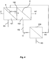
- FIG 4 is a block diagram showing a system comprising two separate screening arrangements in which the first screening arrangement 100 is a combined screening arrangement comprising two screening stages, a first screening stage 101 and a second screening stage 102. Pulp is fed to the first screening arrangement as a first inject I1. In the first screening stage 101, pulp is separated into a first accept portion A1 and a first reject portion R1. The first reject portion R1 is taken out of the screening arrangement to be handled separately. The first accept portion A1 is fed within the first screening arrangement 100 to the second screening stage 102, where it is separated into a second accept portion A2 and a second reject portion R2. The second accept portion A2 is fed forward in the processing line to the next processing step.
- the first screening arrangement 100 is a combined screening arrangement comprising two screening stages, a first screening stage 101 and a second screening stage 102. Pulp is fed to the first screening arrangement as a first inject I1. In the first screening stage 101, pulp is separated into a first accept portion A1 and a first reject portion R1. The first reject portion R1
- the system further comprises a second screening arrangement 200, which is arranged to follow subsequently upon the first screening arrangement 100, meaning that a reject portion R2 from the second screening stage 102 is fed as an inject I3 to the second screening arrangement 200.
- the second screening arrangement 200 is normally a screen with finer slots or holes than the second screening stage 102, or about the same.
- the pulp is in the second screening arrangement 200 separated into a third accept portion A3 and a third reject portion R3.
- the third accept portion A3 is returned to the first screening arrangement 100 and together with the first accept portion A1 fed as a second inject I2 (A1+A3) to the second screening stage 102.
- FIG. 5 is a block diagram showing a system comprising three separate screening arrangements in which the first screening arrangement 100 is a combined screening arrangement comprising two screening stages.
- accept may also be returned from a subsequent third screening arrangement 300.
- This screening arrangement is used to screen the reject portion R1 from the first screening stage 101 of the first screening arrangement 100.
- the reject portion R1 is thus divided into an accept portion A4 and a reject portion R4.
- the accept portion A4 may, as illustrated, be returned to the second screening stage 102 of the first screening arrangement 100. It is possible to return only the accept A4 from the third screening arrangement 300, excluding the accept A3 from the second screening arrangement 200, but more preferably both accepts A3 and A4 are returned to be screened through the second screening stage 102 of the first screening arrangement 100.
Landscapes
- Engineering & Computer Science (AREA)
- Mechanical Engineering (AREA)
- Paper (AREA)
- Separation Of Solids By Using Liquids Or Pneumatic Power (AREA)
Description
- The present invention relates to treatment of cellulose pulp and in particular to a screening arrangement for cellulose pulp and a system and a method for screening of cellulose pulp.
- When preparing a cellulose pulp to be used for further processing, such as for example papermaking or the like, a number of "standard" operations are often performed. For chemical pulp, lignin of wood chips is dissolved in a digester in order to separate the fibers within the wood chip from each other. The cooked pulp is then transported to washing and screening arrangements. During cooking, not all wood chips are equally well digested and the resulting pulp thus contains not only individually separated fibers, but also pieces of uncooked wood chips, knots and fiber bundles known as shives. The shives, knots and other impurities (e.g. sand, bark) still remaining in the pulp may cause problems in later stages of the pulp processing and thus needs to be removed. There are a number of well-known operations used, separately or in combination, to separate impurities from the pulp, including sedimentation, screening and vortex cleaning.
- Screening refers to an operation in which fibers of a pulp suspension pass through a perforated plate with holes or slots, while the impurities are retained. The fraction of pulp passing the plate is referred to as the accept fraction or simply the accept. The fraction of pulp not passing through the openings of the plate is referred to as the reject fraction or simply the reject. The pulp fraction fed to the perforated plate is referred to as the inject fraction or simply the inject. An inject can thus be said to be a pulp flow about to be divided into an accept and a reject. Instead of a perforated plate, slots for separation may be created in other ways, e.g. through forming a screen basket of longitudinal bars.
- In a pulp mill, there are often several screening operations at different locations throughout the process. For example there is often a primary screening operation, in connection with the pulp being washed and dewatered, and an after-screening operation after bleaching of the pulp. Each screening operation can, and often will be, performed in several stages. One single screening apparatus is often not sufficient to separate all impurities in one stage. In order to achieve a good screening efficiency, the reject flow has to be sufficiently large to make sure that the impurities not passing the screen are brought out of the screening apparatus. In case the reject flow is too small, impurities may be retained in the screening chamber where they could cause unnecessary wear on the screen. Since the reject flow has to be of a certain magnitude, this implies that a large number of "good" fibers (i.e. fibers that would belong to the accept) is not given enough time to pass the perforated plate or through slots between longitudinal bars but instead becomes a part of the reject. The accept portion from the screening stage is passed to the next processing step while the reject portion is passed to a subsequent screening stage, in order to be screened again. In order to minimize fiber losses, the accept from the subsequent screening stage is then returned to the inject of the preceding screening stage. In that way, most of the "good" fibers are recovered.
- There are several different kinds of screening apparatuses. One commonly used screening apparatus is a so-called combi-screen, meaning that two or several screening stages are combined within the same screen housing. An example of such an apparatus is disclosed in
EP 1 165 882 - The screening apparatus comprises a screen housing with an upper chamber highest up in the screen housing, a rotor means, which housing is rotary about a rotor shaft, and at least two coaxially arranged screen means. A first tubular screen means divides the interior of the screen housing in radial direction into a first screen chamber located outside the first screen means with an outer defining surface, and a first accept chamber located inside the first screen means. A second tubular screen means divides the interior of the screen housing, so that a second screen chamber is formed between the second screen means and an inner defining surface. The first screen means has a smaller diameter than the second screen means and at least partially is located inside the second screen means. The screening apparatus further comprises an inlet means for fiber suspension to the screening apparatus, at least one reject outlet for reject from the screening apparatus, and at least one accept outlet means for accept from the screening apparatus. This document forms the preamble of
present claim 1. - Combi-screens have been developed in order to bring about a cheaper process where two different screening apparatuses are combined into one apparatus, eliminating the need for e.g. a separate knotter. There are also other kinds of multistage screens in which several screening stages are combined within the same apparatus. For example the separate screening stages may be arranged via screens on top of each other or by one high screening basket divided into separate screening sections
- While using a combi-screen, it is not possible to return the accept from a subsequent screening stage after the combi-screen to its directly preceding screening stage, such as e.g. a fine screen contained within the combi-screen. The accept portion from the subsequent screening stage (at this stage not containing any larger particles), when returned to a combi-screen, will have to pass both screening stages within the combi-screen again, which implies an unnecessary load on the coarse screen. Part of the pulp entering the coarse screen has then already been screened for larger impurities and does not need the coarse screening stage. The return flow from the subsequent screening stage can submit to about 15-20% of the main flow into the combi-screen. This implies that the pump before the combi-screen must be dimensioned to handle a larger flow, in case the return flow is to be added before the pump. Even if the flow is added after the pump, the coarse screen still has to be dimensioned to be able to handle the larger flow. All of these measures render a more expensive process.
- A general object of the invention is to provide an improved system and arrangement for screening of cellulose pulp. A specific object is to achieve a more efficient way of screening minimizing fiber losses, at the same time keeping the number of individual screening apparatuses as few as possible in order to minimize the total investment cost. Another object is to achieve a screening system and an arrangement where the screening means and associated equipment does not have to be overdimensioned, also in order to minimize the investment cost.
- These objects are achieved in accordance with the attached claims.
- Briefly, the present invention proposes a screening arrangement, a system and a method for screening in which a fiber fraction can be returned from at least one subsequent screening arrangement to a first screening arrangement, the first screening arrangement being an arrangement in which at least two screening stages, e.g. a coarse screen and a fine screen, are combined in one apparatus, in such a way that the returned fiber fraction or fiber fractions from the at least one subsequent screening arrangement enters as inject to a second screening means (e.g. a fine screen) of the first screening arrangement and is screened only through the second screening means of the first screening arrangement.
- The invention proposes an arrangement for screening of cellulose pulp in several stages comprising at least two screening means within the same apparatus where the screening means having openings for allowing certain fractions of cellulose pulp to pass through the screens. The screening means are enclosed by a housing and the arrangement further comprises a main inlet for input of pulp to the screening arrangement, at least one outlet for output of an accept fraction of pulp from the screening arrangement, and at least one outlet for output of a reject fraction. The arrangement further comprises a first screening chamber being arranged to receive pulp from the main inlet for input of pulp, a first accept chamber being arranged to receive pulp passing through a first screening means and a second screening chamber being arranged to receive pulp at least from the first accept chamber before screening through a second screening means and the screening arrangement further comprises a secondary pulp inlet for input of pulp from a subsequent screening arrangement to be screened through the second screening means.
- More specifically, in accordance with the invention is provided a screening arrangement, a system and a method for screening in which the first screening arrangement is provided with a secondary pulp inlet separated from a main pulp inlet, the secondary pulp inlet arranged so that pulp entering the mentioned inlet is merged with the accept fraction of the first screening means in order to form an inject to be fed to the second screening means.
- According to one embodiment, the screening means are arranged co-axially and the first screening means is rotatably arranged at least partly within the second screening means. According to one embodiment, the size of the openings of the first and second screening means are different for the respective screening means.
- According to another embodiment, the first screening means is a coarse screen and the second screening means is a fine screen with openings smaller than the first screening means and the main inlet for input of pulp is arranged so that the pulp from the main inlet is fed to the coarse screen.
- The secondary pulp inlet may be arranged in the lower part of the screen, e.g. through a gable of the screen housing. Alternatively, the secondary pulp inlet may be arranged in the upper part of the screening arrangement, e.g. arranged to go through a cover of the housing enclosing the screening means.
- According to another embodiment, a secondary pulp inlet chamber is arranged to receive the pulp entering the secondary pulp inlet. The secondary pulp inlet can be arranged below the first screening means so that, in operation, a secondary pulp flow will enter the secondary inlet chamber from below. The secondary inlet chamber may be arranged, seen in a circumferential direction, between a bearing unit centrally placed in the screening arrangement and a stator enclosed within the first screening means.
- According to another embodiment, the secondary inlet chamber and the first accept chamber are in connection with each other.
- The secondary pulp inlet may consist of a connection piece arranged to fit within the largest diameter of the screening arrangement. In that way, any extra piping or the like sticking out from the screening arrangement is avoided. The screening arrangement thus maintains a compact design.
- The invention further relates to a system comprising a first screening arrangement as described above and further at least one subsequent screening arrangement, the respective screening arrangements being arranged to, during operation, allow an accept fraction/accept fractions of at least one subsequent screening arrangement to be returned to the first screening arrangement via the secondary pulp inlet. Several accept fractions from different subsequent screening arrangements could thus be returned to the first screening arrangement. According to a further embodiment of the system, the secondary pulp inlet is arranged so as to enable mixing of the accept fraction of at least one subsequent screening arrangement with the accept fraction of the first screening means of the first screening arrangement to form an inject fraction to the second screening means of the first screening arrangement.
- The invention also relates to a method for screening a cellulose pulp suspension, using the system described above, in which an accept fraction from at least one subsequent screening arrangement is returned to an inject fraction to a second screening means of a first screening arrangement via a secondary pulp inlet, the accept fraction from the subsequent screening arrangement being screened through the second screening means only. It is to be understood that several accept fractions from different subsequent screening arrangements could be returned, as well as only the accept fraction of a certain subsequent screening arrangement. According to an embodiment of the method, the accept portions of at least one of the subsequent screening arrangements and the first screening stage of the first screening arrangement are mixed before entering the second screening means.
- The invention, together with further objects and advantages thereof, may best be understood by reference to the following description and appended drawings, in which:
-
Fig. 1 is a schematic longitudinal cross-section of a screening arrangement according to an exemplifying embodiment of the present invention; -
Fig. 2 is a transverse cross-section of the screening arrangement illustrated inFig 1 , the cross-section A-A ofFig. 1 -
Fig. 3 shows a schematic cross-section of an alternative embodiment of the screening arrangement -
Fig. 4 shows a block diagram of a screening system comprising a screening arrangement as illustrated inFigs. 1-3 -
Fig. 5 shows a block diagram of another screening system comprising a screening arrangement as illustrated inFigs. 1-3 - In the drawings, similar or corresponding elements will be denoted by the same reference numbers.
- It should be noted that, although the following description primarily refers to a combined screening arrangement in which a fine screen is located outwardly of a coarse screen, seen from the centre of the screening arrangement, the teachings are applicable also on "inside-out" arrangements, i.e. where the fine screen is located on the inside of the coarse screen. Inside-out arrangements with the coarse screen located on the outside of the fine screen hence lie within the scope of the present invention. It is also to be noted that the teachings are applicable to all kinds of such combi-screens combining a coarse and a fine screen within the same apparatus, as well as other multi-stage screens where several screening stages are performed in the same arrangement. The teachings are thus applicable irrespective of whether the multi-stage screening apparatus contains a coarse screen or not. The screening means in the different stages may for example be of the same kind with openings of the same size. The screening means could also be located on the same diameter, i.e. on top of each other.
- The
screening apparatus 100 inFigure 1 comprises ascreen housing 1 with anupper portion 2 and alower portion 3. The housing can preferably be pressurized. Thelower portion 3 ends in agable 29 which is placed on aframe 30. In the screen housing, a first screening means 4 is arranged on a rotor means 5 which is rotatable about arotor shaft 6 contained in abearing unit 7. The first screening means has a cylindrical shape and is located partially in thelower portion 3 of the screening arrangement. The first screening means 4 is arranged to rotate with the rotor means 5. A second screening means 8 is located in theupper portion 2 of thescreening arrangement 100. The second screening means 8 is arranged coaxially with the first screening means 4 and has a greater diameter than the first screening means 4. At least a part of the first screening means 4 is arranged within at least a part of the second screening means 8. The first and second screening means may also be located vice versa. They may further be arranged on the same diameter, in that case none within the other but instead on top of each other. - A
first screening chamber 9 is formed with aguide surface 10 being one limiting surface, outwardly in the circumferential direction, and the screening means 4 being the other, in the inward direction. Theguide surface 10 is a cylindrical tubular means arranged coaxially with the first screening means 4, having a diameter larger than the first screening means 4 so that a space is formed between the screening means and the guide surface. Theguide surface 10 is arranged to extend in an upward direction so that a substantial part of the first screening means 4 is surrounded by the guiding surface. This arrangement forces the pulp flow from amain pulp inlet 11 to enter thefirst screening chamber 9 mainly in the vicinity of the upper part of the first screening means 4. In this way a downward flow is created, which aids the reject flow since a reject from the first screening means 4 is to be taken out from the lower part of the screening arrangement via afirst reject outlet 15. - In operation, a pulp flow to be screened enters the
first screening chamber 9 through themain pulp inlet 11 and the pulp is then fed towards the first screening means 4. The pulp inlet is in the illustrated embodiment placed in thelower portion 3 of the screening arrangement, although near the middle of the screening arrangement. As previously described, the pulp is forced to flow upwardly due to theguide surface 10 in order for the pulp to enter the first screening means 4 at its uppermost location. Fibers of a size smaller than the size of the openings in the perforated screen plate pass through the screening means 4 and enter a first acceptchamber 12. The accept chamber is limited by the screening means 4 and by astator 13 located inside the screening means 4. The stator is a stationary part, preferably cylindrical and provided with at least one pulse means 14. The pulse means 14 are arranged upon rotation of the rotary screening means 4 to create pressure pulses for clearing the first screening means 4. The screening is performed from the outside- in, which is preferable due to the centrifugal force preventing large and heavy particles being in close contact with the screening means. This first screening stage can preferably perform the task of separating mainly larger impurities (e.g. knots), such a screening stage commonly known as a knotter. - The reject portion, i.e. the particles not passing through the screen, is taken out through a
reject outlet 15. This reject portion is also denoted the coarse reject in case the first screening means is a coarse screen. The accept fraction is further fed to asecond screening chamber 16 to form an inject to the second screening means 8. The pulp passing the second screening means 8 is taken out through an acceptoutlet 26 while the reject portion is taken out through at least onereject outlet 27. - A
secondary pulp inlet 17 is arranged so that pulp flowing through the secondary inlet is mixed with the accept portion from the first screening means 4 before entering the second screening means 8. The pulp entering thesecondary inlet 17 consists of an accept fraction from a subsequent screening arrangement (not illustrated in this figure) in which the reject from the second screening means 8 has been screened again. The accept portion of the subsequent screening arrangement, together with the accept portion from the first screening means 4 in thescreening arrangement 100, forms the inject to the second screening means 8. In this way, the "good fibers" contained in the reject portion from the second screening means 8 is brought back to the pulp flow moving along in the process and fiber losses are minimized. Pulp from thesecondary inlet 17 enters a secondarypulp inlet chamber 18. The secondarypulp inlet chamber 18 is limited inwardly, seen in the circumferential direction, by the bearingunit 7 and outwardly by thestator 13. Thesecondary inlet chamber 18 could also be arranged within thebearing unit 7, with thesecondary inlet 17 placed below the bearing unit. In such a case, at least one opening will be provided in the outward wall of the bearing unit for transport of the pulp towards thesecond screening chamber 16. In the embodiment shown infig 3 , thesecondary inlet chamber 18 at least partly coincides with thesecond screening chamber 16. - In a preferred embodiment, the first screening means is a coarse screen and the second screening means is a fine screen. By the term coarse screen is meant a screen designed primarily to separate larger impurities such as knots. Typically the openings may be 6-10 mm, normally 8-10 mm in diameter. By the term fine screen is meant a screen designed to primarily separate shives from fibers. For a slotted fine screen, the slots may be in the range of 0.15-0.60 mm, typically 0.15-0.40 mm. Slots or holes may be used dependent on which process parameters are to be optimized.
- In
figures 1 and2 thesecondary pulp inlet 17 is located in the lower portion of thescreening apparatus 100, e.g. below thegable 29 of thescreen housing 1. Preferably the inlet consists of a connection piece adapted to fit within the largest diameter of the screening arrangement. This placement gives the advantage of eliminating any extra piping protruding from the screening arrangement. Thesecondary pulp inlet 17 is located in such a way that pulp flowing through the inlet is fed into thesecondary inlet chamber 18. For example, thesecondary pulp inlet 17 may be arranged to have aninlet opening 19 below anopening 28 in thegable 29 of thescreen housing 1. From thesecondary inlet chamber 18 the pulp is transported to thesecond screening chamber 16 to be passed through the second screening means 8. In one embodiment, thesecondary inlet chamber 18 and the first acceptchamber 12 is in connection with each other at its respective lower portion via aconnection portion 20 as well as at its respective upper portion via asecond connection portion 25. At least a part of the accept from the first screening stage in the first screening arrangement can thus flow into thesecondary inlet chamber 18 from below and merge with the accept from the subsequent screening stage of the second screening arrangement (not shown). A part of the accept from the first acceptchamber 12 will enter thesecond screening chamber 16 directly, flowing upwardly in the screening arrangement. However, due to theconnection portion 25 the flow from the first acceptchamber 12 going in an upward direction will also be at least partly mixed with the flow from thesecondary inlet chamber 18 before entering thesecond screening chamber 16. Since the flow entering thesecondary pulp inlet 17 and the flow in the first acceptchamber 12 may differ in concentration, it is preferable to merge the flows before entering the second screening chamber in order to create a homogeneous flow to the second screening means 8. -
Figure 2 illustrates a cross-section A-A of a screening arrangement according to the embodiment shown inFigure 1 . Thesecondary pulp inlet 17 is here arranged as a connection piece comprising anouter connection flange 21 and aninner inlet opening 19. Theinlet opening 19 is in communication with thesecondary inlet chamber 18, and may also be in communication with the first acceptchamber 12. In the figure the inlet opening is placed mainly underneath the first acceptchamber 12. In this case, the first acceptchamber 12 and thesecondary inlet chamber 18 are in communication via theconnection portion 20. The flow through thesecondary pulp inlet 17 thus enters thesecondary inlet chamber 18 via theconnection portion 20. Theinlet opening 19 may, however, be placed such that direct access is made to thesecondary inlet chamber 18. -
Figure 3 shows a screening arrangement where thesecondary pulp inlet 17 is located in thecover 22 of thescreen housing 1. The accept from at least one subsequent screening arrangement is fed through thesecondary pulp inlet 17 in thecover 22 of thescreening housing 1 and enters thescreening chamber 16. According to the embodiment illustrated, aconnection piece 23a is arranged within the cover and pulp fed through thesecondary pulp inlet 17 is in thesecond screening chamber 16 mixed with the accept portion from the first acceptchamber 12 flowing up through the rotor means 5. The rotor means is preferably arranged with rotor pulse means 24 in order to create suction pulses to clean the second screening means 8. Alternatively, aconnection piece 23b, located in the centre of thecover 22 may be used as asecondary pulp inlet 17. The location of thesecondary pulp inlet 17 should be chosen to optimize mixing with the flow from the first acceptchamber 12 in order to create a homogeneous flow to the second screening means 8. -
Figure 4 is a block diagram showing a system comprising two separate screening arrangements in which thefirst screening arrangement 100 is a combined screening arrangement comprising two screening stages, afirst screening stage 101 and asecond screening stage 102. Pulp is fed to the first screening arrangement as a first inject I1. In thefirst screening stage 101, pulp is separated into a first accept portion A1 and a first reject portion R1. The first reject portion R1 is taken out of the screening arrangement to be handled separately. The first accept portion A1 is fed within thefirst screening arrangement 100 to thesecond screening stage 102, where it is separated into a second accept portion A2 and a second reject portion R2. The second accept portion A2 is fed forward in the processing line to the next processing step. The system further comprises asecond screening arrangement 200, which is arranged to follow subsequently upon thefirst screening arrangement 100, meaning that a reject portion R2 from thesecond screening stage 102 is fed as an inject I3 to thesecond screening arrangement 200. Thesecond screening arrangement 200 is normally a screen with finer slots or holes than thesecond screening stage 102, or about the same. The pulp is in thesecond screening arrangement 200 separated into a third accept portion A3 and a third reject portion R3. According to the invention, the third accept portion A3 is returned to thefirst screening arrangement 100 and together with the first accept portion A1 fed as a second inject I2 (A1+A3) to thesecond screening stage 102. -
Figure 5 is a block diagram showing a system comprising three separate screening arrangements in which thefirst screening arrangement 100 is a combined screening arrangement comprising two screening stages. In this embodiment, accept may also be returned from a subsequentthird screening arrangement 300. This screening arrangement is used to screen the reject portion R1 from thefirst screening stage 101 of thefirst screening arrangement 100. The reject portion R1 is thus divided into an accept portion A4 and a reject portion R4. The accept portion A4 may, as illustrated, be returned to thesecond screening stage 102 of thefirst screening arrangement 100. It is possible to return only the accept A4 from thethird screening arrangement 300, excluding the accept A3 from thesecond screening arrangement 200, but more preferably both accepts A3 and A4 are returned to be screened through thesecond screening stage 102 of thefirst screening arrangement 100. - Although the invention has been described with reference to specific illustrated embodiments, it is emphasized that it also covers equivalents to the disclosed features, as well as changes and variants obvious to a man skilled in the art. Thus, the scope of the invention is only limited by the appended claims.
Claims (17)
- An arrangement (100) for screening of cellulose pulp in several stages comprising at least two screening means (4,8) within the same apparatus, the screening means (4,8) having openings for allowing certain fractions of cellulose pulp to pass through the screening means, the screening means in turn being enclosed by a housing (1), the arrangement further comprising a main inlet (11) for input of pulp to the screening arrangement, at least one outlet (26) for output of an accept fraction of pulp from the screening arrangement, and at least one outlet (15) for output of a reject fraction, the arrangement further comprising a first screening chamber (9) being arranged to receive pulp from the main inlet (11) for input of pulp, a first accept chamber (12) being arranged to receive pulp passing through the first screening means (4) and a second screening chamber (16) being arranged to receive pulp at least from the first accept chamber (12) before screening through a second screening means (8)
characterized in that
the screening arrangement comprises a secondary pulp inlet (17) for input of pulp from at least one subsequent screening arrangement (200, 300), wherein said received pulp is to be screened through the second screening means (8) and the pulp entering the secondary pulp inlet (17) being an accept fraction from the subsequent screening arrangement (200,300). - An arrangement for screening of cellulose pulp according to claim 1, characterized in that
the size of the openings of the first and second screening means are different for the respective screening means (4,8). - An arrangement for screening of cellulose pulp according to claim 1 or 2, characterized in that
the screening means are arranged co-axially and the first screening means (4) is rotatably arranged at least partly within the second screening means (8). - The arrangement of any of claim 1-3, characterized in that
the first screening means (4) is a coarse screen and the second screening means (8) is a fine screen with openings smaller than the first screening means (4) and that the main inlet (11) for input of pulp is arranged so that, in operation, the pulp from the main inlet is fed to the coarse screen (4). - The arrangement of any of claims 1-4, characterized in that
the secondary pulp inlet (17) is arranged in such a way that, during operation, a pulp flow entering the secondary pulp inlet (17) merges with the accept from the first screening means (4) so as to form an inject to the second screening means (8). - The arrangement of any of the previous claims, characterized in that
the secondary pulp inlet (17) is arranged in the lower part of the screening arrangement (100). - The arrangement of any of the previous claims, characterized in that
a secondary pulp inlet chamber (18) is arranged to receive the pulp entering the secondary pulp inlet (17). - The arrangement of claim 7, characterized in that
the secondary pulp inlet (17) is arranged below the first screening means (4) so that, in operation, a secondary pulp flow will enter the secondary inlet chamber (18) from below. - The arrangement of claim 7 or 8, characterized in that
the secondary inlet chamber (18) is arranged, seen in a circumferential direction, between a bearing unit (7) centrally placed in the screening arrangement and a stator (13) enclosed within the first screening means (4). - The arrangement of any of claims 7-9, characterized in that
the secondary inlet chamber (18) and the first accept chamber (12) are in connection with each other. - The arrangement of any of claims 6-10, characterized in that
the secondary pulp inlet (17) consists of a connection piece arranged to fit within the largest diameter of the screening arrangement. - The arrangement of any of claims 1-5, characterized in that
the secondary pulp inlet (17) is arranged in the upper part of the screening arrangement (100). - The arrangement of claim 12, characterized in that
the secondary pulp inlet (17) is arranged to go through the cover (22) of the housing (1) enclosing the screening means (4,8). - A system comprising a first screening arrangement (100) according to any of the preceding claims, characterized in that the system comprises at least one subsequent screening arrangement (200, 300), the respective screening arrangements being arranged to, during operation, allow an accept fraction (A3, A4) of at least one subsequent screening arrangement (200, 300) to be returned to the second screening stage (102) of the first screening arrangement (100) via a secondary pulp inlet (17).
- A system according to claim 14, characterized in that
the secondary pulp inlet (17) is arranged so that, in operation, the accept fraction (A3, A4) of at least one subsequent screening arrangement (200, 300) is mixed with the accept fraction (A1) of the first screening means (4) of the first screening arrangement (100) to form an inject fraction to the second screening means (8) of the first screening arrangement (100). - A method for screening a cellulose pulp suspension using the system of claim 14, in which an accept fraction (A3, A4) from at least one subsequent screening arrangement is returned as an inject fraction to a second screening stage (102) of a first screening arrangement (100) via a secondary pulp inlet (17), the accept fraction (A3) from the subsequent screening arrangement being screened through the second screening means (8) of the first screening arrangement (100).
- A method according to claim 16, characterized in that
the accept fraction (A3, A4) from at least one subsequent screening arrangement (200, 300) is mixed with the accept fraction (A1) of a first screening stage (101) of the first screening arrangement (100) before being screened through the second screening means (8).
Applications Claiming Priority (2)
| Application Number | Priority Date | Filing Date | Title |
|---|---|---|---|
| SE0900351A SE533736C2 (en) | 2009-03-19 | 2009-03-19 | Device, system and method for treating cellulose pulp |
| PCT/SE2010/050266 WO2010107369A1 (en) | 2009-03-19 | 2010-03-09 | Arrangement, system and method for treatment of cellulose pulp |
Publications (3)
| Publication Number | Publication Date |
|---|---|
| EP2408962A1 EP2408962A1 (en) | 2012-01-25 |
| EP2408962A4 EP2408962A4 (en) | 2014-10-01 |
| EP2408962B1 true EP2408962B1 (en) | 2016-05-04 |
Family
ID=42739851
Family Applications (1)
| Application Number | Title | Priority Date | Filing Date |
|---|---|---|---|
| EP10753767.2A Active EP2408962B1 (en) | 2009-03-19 | 2010-03-09 | Arrangement, system and method for treatment of cellulose pulp |
Country Status (7)
| Country | Link |
|---|---|
| US (1) | US8303769B2 (en) |
| EP (1) | EP2408962B1 (en) |
| JP (1) | JP5750095B2 (en) |
| CN (1) | CN102356195B (en) |
| CA (1) | CA2755430C (en) |
| SE (1) | SE533736C2 (en) |
| WO (1) | WO2010107369A1 (en) |
Families Citing this family (2)
| Publication number | Priority date | Publication date | Assignee | Title |
|---|---|---|---|---|
| DE102013010959B3 (en) * | 2013-07-01 | 2014-08-07 | Andritz Fiedler Gmbh | screening device |
| CN108166301B (en) * | 2017-12-26 | 2023-08-18 | 郑州运达造纸设备有限公司 | Multifunctional pressure screen rotor structure |
Family Cites Families (10)
| Publication number | Priority date | Publication date | Assignee | Title |
|---|---|---|---|---|
| US2364171A (en) * | 1940-07-08 | 1944-12-05 | Black Clawson Co | Pulp screen |
| SE441758B (en) * | 1984-04-03 | 1985-11-04 | Sunds Defibrator | SET AND DEVICE FOR CONTINUOUS TREATMENT OF MATERIAL SUSPENSIONS |
| JP2986525B2 (en) * | 1990-10-01 | 1999-12-06 | 相川鉄工株式会社 | Deinking method for recycled paper |
| FI93979C (en) | 1993-08-20 | 1995-06-26 | Tampella Oy Valmet | Method and pressure sorter for sorting pulp |
| JP3065202B2 (en) * | 1993-10-20 | 2000-07-17 | 石川島播磨重工業株式会社 | Waste Paper Pulp Sorting Method and Apparatus |
| SE9901148L (en) | 1999-03-29 | 2000-06-12 | Valmet Fibertech Ab | Screening device with a rotatable and stationary screen means |
| JP3443361B2 (en) * | 1999-04-23 | 2003-09-02 | 相川鉄工株式会社 | Screen device |
| FI113670B (en) * | 1999-12-09 | 2004-05-31 | Upm Kymmene Corp | Process for making printing paper |
| US6416622B2 (en) * | 2000-02-04 | 2002-07-09 | Georgia-Pacific Corporation | Hybrid multistage forward cleaner system with flotation cell |
| FI110619B (en) * | 2000-10-16 | 2003-02-28 | Metso Paper Inc | Method and apparatus for sorting mechanical pulp |
-
2009
- 2009-03-19 SE SE0900351A patent/SE533736C2/en unknown
-
2010
- 2010-03-09 CA CA2755430A patent/CA2755430C/en active Active
- 2010-03-09 US US13/256,847 patent/US8303769B2/en not_active Expired - Fee Related
- 2010-03-09 WO PCT/SE2010/050266 patent/WO2010107369A1/en not_active Ceased
- 2010-03-09 JP JP2012500741A patent/JP5750095B2/en not_active Expired - Fee Related
- 2010-03-09 EP EP10753767.2A patent/EP2408962B1/en active Active
- 2010-03-09 CN CN201080012913.5A patent/CN102356195B/en active Active
Also Published As
| Publication number | Publication date |
|---|---|
| EP2408962A4 (en) | 2014-10-01 |
| US20120000619A1 (en) | 2012-01-05 |
| CN102356195B (en) | 2016-02-24 |
| SE0900351A1 (en) | 2010-09-20 |
| SE533736C2 (en) | 2010-12-21 |
| CA2755430C (en) | 2016-11-22 |
| WO2010107369A1 (en) | 2010-09-23 |
| JP5750095B2 (en) | 2015-07-15 |
| US8303769B2 (en) | 2012-11-06 |
| CA2755430A1 (en) | 2010-09-23 |
| CN102356195A (en) | 2012-02-15 |
| EP2408962A1 (en) | 2012-01-25 |
| JP2012520948A (en) | 2012-09-10 |
Similar Documents
| Publication | Publication Date | Title |
|---|---|---|
| CA2133630C (en) | Method and apparatus for screening waste paper pulp | |
| CA2013011C (en) | Method and means for treating pulp | |
| US20130206881A1 (en) | Pulper comprising a screening sheet | |
| FR2521607A1 (en) | DERIVATIVE CIRCUIT SYSTEM FOR PROCESSING OLD PAPER | |
| JPH11222789A (en) | Waste paper pulp sorting method and apparatus | |
| CN102747631B (en) | Repulping apparatus used for decomposing fiber material and method thereof | |
| US4067800A (en) | Screening apparatus | |
| CA2755430C (en) | Arrangement, system and method for treatment of cellulose pulp | |
| FI120629B (en) | Apparatus and method for preparing a pulp suspension | |
| EP2547824B1 (en) | Pressure filter | |
| US5882475A (en) | Method of recovering fibers from a reject stream generated in a wastepaper treating process | |
| US20030201213A1 (en) | Combined sand and liquor separation for chip transport in pulp processing | |
| CN105008615B (en) | Method for forming and handling fibrous suspension | |
| CN102666978B (en) | Unit, structure and method for screening cellulose pulp | |
| EP1612326B1 (en) | Pressure screen for screening a fibrous suspension | |
| EP3430197B1 (en) | Method for screening and a screening apparatus | |
| EP1664422B1 (en) | A thickener for concentration of fibre suspensions | |
| EP2994568B1 (en) | An apparatus for separating particles in a pulp suspension | |
| FI118691B (en) | Screening fibrous pulp suspensions - using simplified low capital cost single pump processing means | |
| JPH06192982A (en) | Device for macerating and dust removing for papermaking |
Legal Events
| Date | Code | Title | Description |
|---|---|---|---|
| PUAI | Public reference made under article 153(3) epc to a published international application that has entered the european phase |
Free format text: ORIGINAL CODE: 0009012 |
|
| 17P | Request for examination filed |
Effective date: 20111019 |
|
| AK | Designated contracting states |
Kind code of ref document: A1 Designated state(s): AT BE BG CH CY CZ DE DK EE ES FI FR GB GR HR HU IE IS IT LI LT LU LV MC MK MT NL NO PL PT RO SE SI SK SM TR |
|
| DAX | Request for extension of the european patent (deleted) | ||
| RAP1 | Party data changed (applicant data changed or rights of an application transferred) |
Owner name: VALMET TECHNOLOGIES, INC. |
|
| A4 | Supplementary search report drawn up and despatched |
Effective date: 20140903 |
|
| RIC1 | Information provided on ipc code assigned before grant |
Ipc: D21D 5/02 20060101AFI20140828BHEP |
|
| GRAP | Despatch of communication of intention to grant a patent |
Free format text: ORIGINAL CODE: EPIDOSNIGR1 |
|
| INTG | Intention to grant announced |
Effective date: 20151214 |
|
| GRAS | Grant fee paid |
Free format text: ORIGINAL CODE: EPIDOSNIGR3 |
|
| GRAA | (expected) grant |
Free format text: ORIGINAL CODE: 0009210 |
|
| AK | Designated contracting states |
Kind code of ref document: B1 Designated state(s): AT BE BG CH CY CZ DE DK EE ES FI FR GB GR HR HU IE IS IT LI LT LU LV MC MK MT NL NO PL PT RO SE SI SK SM TR |
|
| REG | Reference to a national code |
Ref country code: GB Ref legal event code: FG4D |
|
| REG | Reference to a national code |
Ref country code: CH Ref legal event code: EP |
|
| REG | Reference to a national code |
Ref country code: AT Ref legal event code: REF Ref document number: 797018 Country of ref document: AT Kind code of ref document: T Effective date: 20160515 |
|
| REG | Reference to a national code |
Ref country code: IE Ref legal event code: FG4D |
|
| REG | Reference to a national code |
Ref country code: DE Ref legal event code: R096 Ref document number: 602010033083 Country of ref document: DE |
|
| REG | Reference to a national code |
Ref country code: NL Ref legal event code: MP Effective date: 20160504 |
|
| REG | Reference to a national code |
Ref country code: LT Ref legal event code: MG4D |
|
| PG25 | Lapsed in a contracting state [announced via postgrant information from national office to epo] |
Ref country code: LT Free format text: LAPSE BECAUSE OF FAILURE TO SUBMIT A TRANSLATION OF THE DESCRIPTION OR TO PAY THE FEE WITHIN THE PRESCRIBED TIME-LIMIT Effective date: 20160504 Ref country code: NO Free format text: LAPSE BECAUSE OF FAILURE TO SUBMIT A TRANSLATION OF THE DESCRIPTION OR TO PAY THE FEE WITHIN THE PRESCRIBED TIME-LIMIT Effective date: 20160804 Ref country code: NL Free format text: LAPSE BECAUSE OF FAILURE TO SUBMIT A TRANSLATION OF THE DESCRIPTION OR TO PAY THE FEE WITHIN THE PRESCRIBED TIME-LIMIT Effective date: 20160504 |
|
| PG25 | Lapsed in a contracting state [announced via postgrant information from national office to epo] |
Ref country code: PT Free format text: LAPSE BECAUSE OF FAILURE TO SUBMIT A TRANSLATION OF THE DESCRIPTION OR TO PAY THE FEE WITHIN THE PRESCRIBED TIME-LIMIT Effective date: 20160905 Ref country code: SE Free format text: LAPSE BECAUSE OF FAILURE TO SUBMIT A TRANSLATION OF THE DESCRIPTION OR TO PAY THE FEE WITHIN THE PRESCRIBED TIME-LIMIT Effective date: 20160504 Ref country code: ES Free format text: LAPSE BECAUSE OF FAILURE TO SUBMIT A TRANSLATION OF THE DESCRIPTION OR TO PAY THE FEE WITHIN THE PRESCRIBED TIME-LIMIT Effective date: 20160504 Ref country code: HR Free format text: LAPSE BECAUSE OF FAILURE TO SUBMIT A TRANSLATION OF THE DESCRIPTION OR TO PAY THE FEE WITHIN THE PRESCRIBED TIME-LIMIT Effective date: 20160504 Ref country code: LV Free format text: LAPSE BECAUSE OF FAILURE TO SUBMIT A TRANSLATION OF THE DESCRIPTION OR TO PAY THE FEE WITHIN THE PRESCRIBED TIME-LIMIT Effective date: 20160504 Ref country code: GR Free format text: LAPSE BECAUSE OF FAILURE TO SUBMIT A TRANSLATION OF THE DESCRIPTION OR TO PAY THE FEE WITHIN THE PRESCRIBED TIME-LIMIT Effective date: 20160805 |
|
| PG25 | Lapsed in a contracting state [announced via postgrant information from national office to epo] |
Ref country code: IT Free format text: LAPSE BECAUSE OF FAILURE TO SUBMIT A TRANSLATION OF THE DESCRIPTION OR TO PAY THE FEE WITHIN THE PRESCRIBED TIME-LIMIT Effective date: 20160504 |
|
| PG25 | Lapsed in a contracting state [announced via postgrant information from national office to epo] |
Ref country code: RO Free format text: LAPSE BECAUSE OF FAILURE TO SUBMIT A TRANSLATION OF THE DESCRIPTION OR TO PAY THE FEE WITHIN THE PRESCRIBED TIME-LIMIT Effective date: 20160504 Ref country code: SK Free format text: LAPSE BECAUSE OF FAILURE TO SUBMIT A TRANSLATION OF THE DESCRIPTION OR TO PAY THE FEE WITHIN THE PRESCRIBED TIME-LIMIT Effective date: 20160504 Ref country code: EE Free format text: LAPSE BECAUSE OF FAILURE TO SUBMIT A TRANSLATION OF THE DESCRIPTION OR TO PAY THE FEE WITHIN THE PRESCRIBED TIME-LIMIT Effective date: 20160504 Ref country code: DK Free format text: LAPSE BECAUSE OF FAILURE TO SUBMIT A TRANSLATION OF THE DESCRIPTION OR TO PAY THE FEE WITHIN THE PRESCRIBED TIME-LIMIT Effective date: 20160504 Ref country code: CZ Free format text: LAPSE BECAUSE OF FAILURE TO SUBMIT A TRANSLATION OF THE DESCRIPTION OR TO PAY THE FEE WITHIN THE PRESCRIBED TIME-LIMIT Effective date: 20160504 |
|
| REG | Reference to a national code |
Ref country code: DE Ref legal event code: R097 Ref document number: 602010033083 Country of ref document: DE |
|
| PG25 | Lapsed in a contracting state [announced via postgrant information from national office to epo] |
Ref country code: SM Free format text: LAPSE BECAUSE OF FAILURE TO SUBMIT A TRANSLATION OF THE DESCRIPTION OR TO PAY THE FEE WITHIN THE PRESCRIBED TIME-LIMIT Effective date: 20160504 Ref country code: PL Free format text: LAPSE BECAUSE OF FAILURE TO SUBMIT A TRANSLATION OF THE DESCRIPTION OR TO PAY THE FEE WITHIN THE PRESCRIBED TIME-LIMIT Effective date: 20160504 Ref country code: BE Free format text: LAPSE BECAUSE OF FAILURE TO SUBMIT A TRANSLATION OF THE DESCRIPTION OR TO PAY THE FEE WITHIN THE PRESCRIBED TIME-LIMIT Effective date: 20160504 |
|
| PLBE | No opposition filed within time limit |
Free format text: ORIGINAL CODE: 0009261 |
|
| STAA | Information on the status of an ep patent application or granted ep patent |
Free format text: STATUS: NO OPPOSITION FILED WITHIN TIME LIMIT |
|
| 26N | No opposition filed |
Effective date: 20170207 |
|
| PG25 | Lapsed in a contracting state [announced via postgrant information from national office to epo] |
Ref country code: SI Free format text: LAPSE BECAUSE OF FAILURE TO SUBMIT A TRANSLATION OF THE DESCRIPTION OR TO PAY THE FEE WITHIN THE PRESCRIBED TIME-LIMIT Effective date: 20160504 |
|
| REG | Reference to a national code |
Ref country code: DE Ref legal event code: R119 Ref document number: 602010033083 Country of ref document: DE |
|
| REG | Reference to a national code |
Ref country code: CH Ref legal event code: PL |
|
| GBPC | Gb: european patent ceased through non-payment of renewal fee |
Effective date: 20170309 |
|
| PG25 | Lapsed in a contracting state [announced via postgrant information from national office to epo] |
Ref country code: MC Free format text: LAPSE BECAUSE OF FAILURE TO SUBMIT A TRANSLATION OF THE DESCRIPTION OR TO PAY THE FEE WITHIN THE PRESCRIBED TIME-LIMIT Effective date: 20160504 |
|
| REG | Reference to a national code |
Ref country code: IE Ref legal event code: MM4A |
|
| REG | Reference to a national code |
Ref country code: FR Ref legal event code: ST Effective date: 20171130 |
|
| PG25 | Lapsed in a contracting state [announced via postgrant information from national office to epo] |
Ref country code: DE Free format text: LAPSE BECAUSE OF NON-PAYMENT OF DUE FEES Effective date: 20171003 Ref country code: LU Free format text: LAPSE BECAUSE OF NON-PAYMENT OF DUE FEES Effective date: 20170309 Ref country code: FR Free format text: LAPSE BECAUSE OF NON-PAYMENT OF DUE FEES Effective date: 20170331 |
|
| PG25 | Lapsed in a contracting state [announced via postgrant information from national office to epo] |
Ref country code: CH Free format text: LAPSE BECAUSE OF NON-PAYMENT OF DUE FEES Effective date: 20170331 Ref country code: GB Free format text: LAPSE BECAUSE OF NON-PAYMENT OF DUE FEES Effective date: 20170309 Ref country code: LI Free format text: LAPSE BECAUSE OF NON-PAYMENT OF DUE FEES Effective date: 20170331 Ref country code: IE Free format text: LAPSE BECAUSE OF NON-PAYMENT OF DUE FEES Effective date: 20170309 |
|
| PG25 | Lapsed in a contracting state [announced via postgrant information from national office to epo] |
Ref country code: MT Free format text: LAPSE BECAUSE OF NON-PAYMENT OF DUE FEES Effective date: 20170309 |
|
| REG | Reference to a national code |
Ref country code: AT Ref legal event code: UEP Ref document number: 797018 Country of ref document: AT Kind code of ref document: T Effective date: 20160504 |
|
| PG25 | Lapsed in a contracting state [announced via postgrant information from national office to epo] |
Ref country code: HU Free format text: LAPSE BECAUSE OF FAILURE TO SUBMIT A TRANSLATION OF THE DESCRIPTION OR TO PAY THE FEE WITHIN THE PRESCRIBED TIME-LIMIT; INVALID AB INITIO Effective date: 20100309 |
|
| PG25 | Lapsed in a contracting state [announced via postgrant information from national office to epo] |
Ref country code: BG Free format text: LAPSE BECAUSE OF FAILURE TO SUBMIT A TRANSLATION OF THE DESCRIPTION OR TO PAY THE FEE WITHIN THE PRESCRIBED TIME-LIMIT Effective date: 20160504 |
|
| PG25 | Lapsed in a contracting state [announced via postgrant information from national office to epo] |
Ref country code: CY Free format text: LAPSE BECAUSE OF NON-PAYMENT OF DUE FEES Effective date: 20160504 |
|
| PG25 | Lapsed in a contracting state [announced via postgrant information from national office to epo] |
Ref country code: MK Free format text: LAPSE BECAUSE OF FAILURE TO SUBMIT A TRANSLATION OF THE DESCRIPTION OR TO PAY THE FEE WITHIN THE PRESCRIBED TIME-LIMIT Effective date: 20160504 |
|
| PG25 | Lapsed in a contracting state [announced via postgrant information from national office to epo] |
Ref country code: TR Free format text: LAPSE BECAUSE OF FAILURE TO SUBMIT A TRANSLATION OF THE DESCRIPTION OR TO PAY THE FEE WITHIN THE PRESCRIBED TIME-LIMIT Effective date: 20160504 |
|
| PG25 | Lapsed in a contracting state [announced via postgrant information from national office to epo] |
Ref country code: IS Free format text: LAPSE BECAUSE OF FAILURE TO SUBMIT A TRANSLATION OF THE DESCRIPTION OR TO PAY THE FEE WITHIN THE PRESCRIBED TIME-LIMIT Effective date: 20160904 |
|
| PGFP | Annual fee paid to national office [announced via postgrant information from national office to epo] |
Ref country code: AT Payment date: 20260318 Year of fee payment: 17 |
|
| PGFP | Annual fee paid to national office [announced via postgrant information from national office to epo] |
Ref country code: FI Payment date: 20260319 Year of fee payment: 17 |