EP2408287A2 - Power bus system and method - Google Patents
Power bus system and method Download PDFInfo
- Publication number
- EP2408287A2 EP2408287A2 EP11174338A EP11174338A EP2408287A2 EP 2408287 A2 EP2408287 A2 EP 2408287A2 EP 11174338 A EP11174338 A EP 11174338A EP 11174338 A EP11174338 A EP 11174338A EP 2408287 A2 EP2408287 A2 EP 2408287A2
- Authority
- EP
- European Patent Office
- Prior art keywords
- groove
- bus
- power
- elongate metal
- bus bar
- Prior art date
- Legal status (The legal status is an assumption and is not a legal conclusion. Google has not performed a legal analysis and makes no representation as to the accuracy of the status listed.)
- Granted
Links
- 238000000034 method Methods 0.000 title claims description 30
- 229910052751 metal Inorganic materials 0.000 claims abstract description 40
- 239000002184 metal Substances 0.000 claims abstract description 40
- 238000001125 extrusion Methods 0.000 claims abstract description 32
- 238000009826 distribution Methods 0.000 claims abstract description 14
- 230000005540 biological transmission Effects 0.000 claims abstract description 9
- 230000008878 coupling Effects 0.000 claims description 20
- 238000010168 coupling process Methods 0.000 claims description 20
- 238000005859 coupling reaction Methods 0.000 claims description 20
- 239000004020 conductor Substances 0.000 claims description 7
- 238000003780 insertion Methods 0.000 claims description 6
- 230000037431 insertion Effects 0.000 claims description 6
- 238000004519 manufacturing process Methods 0.000 claims description 6
- RYGMFSIKBFXOCR-UHFFFAOYSA-N Copper Chemical compound [Cu] RYGMFSIKBFXOCR-UHFFFAOYSA-N 0.000 claims description 4
- 229910052782 aluminium Inorganic materials 0.000 claims description 4
- XAGFODPZIPBFFR-UHFFFAOYSA-N aluminium Chemical compound [Al] XAGFODPZIPBFFR-UHFFFAOYSA-N 0.000 claims description 4
- 229910052802 copper Inorganic materials 0.000 claims description 4
- 239000010949 copper Substances 0.000 claims description 4
- 239000012811 non-conductive material Substances 0.000 claims description 4
- 238000004891 communication Methods 0.000 claims description 2
- 238000007667 floating Methods 0.000 claims description 2
- 230000008569 process Effects 0.000 description 7
- 238000010586 diagram Methods 0.000 description 4
- 239000000463 material Substances 0.000 description 4
- 230000001681 protective effect Effects 0.000 description 4
- 238000006243 chemical reaction Methods 0.000 description 3
- 230000000717 retained effect Effects 0.000 description 3
- 239000011521 glass Substances 0.000 description 2
- 238000007373 indentation Methods 0.000 description 2
- 238000003754 machining Methods 0.000 description 2
- 238000012986 modification Methods 0.000 description 2
- 230000004048 modification Effects 0.000 description 2
- 230000009286 beneficial effect Effects 0.000 description 1
- 230000008859 change Effects 0.000 description 1
- 230000006835 compression Effects 0.000 description 1
- 238000007906 compression Methods 0.000 description 1
- 150000002739 metals Chemical class 0.000 description 1
- 230000001105 regulatory effect Effects 0.000 description 1
- 239000002990 reinforced plastic Substances 0.000 description 1
- 239000004065 semiconductor Substances 0.000 description 1
Images






Classifications
-
- H—ELECTRICITY
- H05—ELECTRIC TECHNIQUES NOT OTHERWISE PROVIDED FOR
- H05K—PRINTED CIRCUITS; CASINGS OR CONSTRUCTIONAL DETAILS OF ELECTRIC APPARATUS; MANUFACTURE OF ASSEMBLAGES OF ELECTRICAL COMPONENTS
- H05K7/00—Constructional details common to different types of electric apparatus
- H05K7/14—Mounting supporting structure in casing or on frame or rack
- H05K7/1438—Back panels or connecting means therefor; Terminals; Coding means to avoid wrong insertion
- H05K7/1457—Power distribution arrangements
-
- H—ELECTRICITY
- H02—GENERATION; CONVERSION OR DISTRIBUTION OF ELECTRIC POWER
- H02B—BOARDS, SUBSTATIONS OR SWITCHING ARRANGEMENTS FOR THE SUPPLY OR DISTRIBUTION OF ELECTRIC POWER
- H02B1/00—Frameworks, boards, panels, desks, casings; Details of substations or switching arrangements
- H02B1/20—Bus-bar or other wiring layouts, e.g. in cubicles, in switchyards
-
- H—ELECTRICITY
- H05—ELECTRIC TECHNIQUES NOT OTHERWISE PROVIDED FOR
- H05K—PRINTED CIRCUITS; CASINGS OR CONSTRUCTIONAL DETAILS OF ELECTRIC APPARATUS; MANUFACTURE OF ASSEMBLAGES OF ELECTRICAL COMPONENTS
- H05K7/00—Constructional details common to different types of electric apparatus
- H05K7/14—Mounting supporting structure in casing or on frame or rack
- H05K7/1422—Printed circuit boards receptacles, e.g. stacked structures, electronic circuit modules or box like frames
- H05K7/1427—Housings
- H05K7/1432—Housings specially adapted for power drive units or power converters
- H05K7/14325—Housings specially adapted for power drive units or power converters for cabinets or racks
-
- H—ELECTRICITY
- H05—ELECTRIC TECHNIQUES NOT OTHERWISE PROVIDED FOR
- H05K—PRINTED CIRCUITS; CASINGS OR CONSTRUCTIONAL DETAILS OF ELECTRIC APPARATUS; MANUFACTURE OF ASSEMBLAGES OF ELECTRICAL COMPONENTS
- H05K7/00—Constructional details common to different types of electric apparatus
- H05K7/14—Mounting supporting structure in casing or on frame or rack
- H05K7/1422—Printed circuit boards receptacles, e.g. stacked structures, electronic circuit modules or box like frames
- H05K7/1427—Housings
- H05K7/1432—Housings specially adapted for power drive units or power converters
- H05K7/14329—Housings specially adapted for power drive units or power converters specially adapted for the configuration of power bus bars
-
- H—ELECTRICITY
- H02—GENERATION; CONVERSION OR DISTRIBUTION OF ELECTRIC POWER
- H02G—INSTALLATION OF ELECTRIC CABLES OR LINES, OR OF COMBINED OPTICAL AND ELECTRIC CABLES OR LINES
- H02G5/00—Installations of bus-bars
- H02G5/02—Open installations
- H02G5/025—Supporting structures
-
- Y—GENERAL TAGGING OF NEW TECHNOLOGICAL DEVELOPMENTS; GENERAL TAGGING OF CROSS-SECTIONAL TECHNOLOGIES SPANNING OVER SEVERAL SECTIONS OF THE IPC; TECHNICAL SUBJECTS COVERED BY FORMER USPC CROSS-REFERENCE ART COLLECTIONS [XRACs] AND DIGESTS
- Y10—TECHNICAL SUBJECTS COVERED BY FORMER USPC
- Y10T—TECHNICAL SUBJECTS COVERED BY FORMER US CLASSIFICATION
- Y10T29/00—Metal working
- Y10T29/49—Method of mechanical manufacture
- Y10T29/49002—Electrical device making
Definitions
- the present invention relates generally to the field of power electronic devices such as those used in power conversion or applying power to motors and similar loads. More particularly, the invention relates to an extruded electrical distribution bus and associated systems and methods.
- circuitry In the field of power electronic devices, a wide range of circuitry is known and currently available for transmitting, converting, producing, and applying power. Depending upon the application, such circuitry may transmit incoming power to various devices and/or convert incoming power from one form to another as needed by a load.
- constant (or varying) frequency alternating current power (such as from a utility grid or generator) is converted to controlled frequency alternating current power to drive motors, and other loads.
- the frequency of the output power can be regulated to control the speed of the motor or other device.
- drive system buses may transmit the power throughout the process.
- a bus system may facilitate transmission of power to a number of system components and devices.
- a motor control center bus may be utilized to provide power to a drive system bus.
- Circuitry such as that detailed above may be employed with differing levels of incoming power for different load requirements. For example, power may be taken from a high voltage electrical grid and converted for use with a high horse power motor or the like. Alternatively, such circuitry may be utilized to simply distribute power to different devices via a motor control center bus. Circuitry for providing such functionality is often packaged together. Indeed, electrical systems with packaged electrical and electronic components, such as drive cabinets and motor control centers, are known and in use. For example, motor control centers (MCCs) are used for power and data distribution in large industrial operations, and drive cabinets are used for power conversion and distribution. In a typical MCC and/or drive cabinet a variety of components are housed in large electrical enclosures that may be subdivided into compartments.
- an MCC may include components such as switchgear, semiconductor power electronic circuits, programmable logic controllers (PLCs), motor controllers, and so forth.
- a drive cabinet may include a rectifier (converter), an inverter, transitional attachments, and so forth. Further, such electrical enclosures may include bus work that communicatively couples the components with a power source and/or other components.
- an extruded high power electrical distribution bus is provided.
- Such a bus can be employed in an MCC, a drive cabinet, or any such electrical enclosure to facilitate transmission of power.
- a body of the bus includes an elongate metal extrusion with first and second ridges extending along a length of the body from opposite edges of the body.
- the bus includes a first groove and a second groove extending along the length of the body and into the body from a face of the body.
- Each of the first and second grooves comprises a cross-section having a narrow passage extending from the face into a broader cavity within the body, such as a T-shaped or L-shaped groove cross-section.
- the bus includes machined openings into each groove, wherein each of the machined openings is wider than the width of the corresponding groove to which it provides access.
- Present embodiments may include a method, such as an extrusion process, for forming an elongate metal extrusion that includes a first ridge and a second ridge extending along a length of a body from opposite edges of the body, and a first groove and a second groove positioned along the length of the body and extending into the body from a face of the body.
- the extrusion process utilizes an extrusion die that generates the first and second grooves within the body such that a cross-section of each groove includes a narrow passage extending from a face of the body into a broadened cavity within the body.
- the method may also include a machining process for providing openings into the grooves such that the grooves can accommodate insertion of an attachment feature having an enlarged distill end and a narrowed neck. Once inserted into the first groove or the second groove, the attachment feature can slide along the groove into which it was inserted and engage the enlarged distill end with the broader cavity and engage the narrowed neck with the narrow passage.
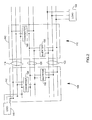
- FIG. 2 is a block diagram of a pair of drive systems utilizing a bus system in accordance with present embodiments
- FIG. 3 is a perspective view of a bus bar that is retained by a pair of support brackets and coupled to a pair of attachment features in accordance with present embodiments;
- FIG. 4 is a perspective view of a bus system disposed within an enclosure in accordance with present embodiments
- FIG. 5 is a perspective view of a perpendicular connection feature coupled to a bus bar in accordance with present embodiments
- FIG. 6 is a cross-sectional view of a bus bar in accordance with present embodiments.
- FIG. 7 illustrates various cross-sectional views of a bus bar with different groove cross-sections in accordance with present embodiments
- FIG. 9 is a perspective view of a support bracket exploded away from a bus bar in accordance with present embodiments.
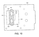
- FIG. 10 is a cross-sectional view of a bus bar inserted into a bracket support in accordance with present embodiments
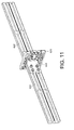
- FIG. 11 is a perspective view of a splicing feature coupling a pair of bus bars in accordance with present embodiments.
- FIG. 12 is a process flow diagram of a method for producing a bus bar system in accordance with present embodiments.
- references in the specification to "one embodiment,” “an embodiment,” or “an exemplary embodiment,” indicate that the embodiment described may include a particular feature, structure, or characteristic, but every embodiment may not necessarily include the particular feature, structure, or characteristic. Moreover, such phrases are not necessarily referring to the same embodiment. Further, when a particular feature, structure, or characteristic is described in connection with an embodiment, it is submitted that it is within the knowledge of one skilled in the art to affect such feature, structure, or characteristic in connection with other embodiments whether or not explicitly described.
- an electrical enclosure 100 is illustrated in which electrical components of various types may be housed and connected via a bus system that includes bus bars, connection features, and a support system.
- the enclosure 100 may be representative of a motor control center or other industrial, commercial, or marine electrical system.
- the enclosure 100 provides a protective shell around various electrical components and the bus system.
- the enclosure 100 may include a shell 102 made of any suitable material, such as heavy gauge sheet metal, reinforced plastic, and so forth.
- the enclosure 100 may include devices such as a programmable logic controller, switches, motor controls, inverters, rectifiers, and so forth disposed along and/or coupled with the bus system.
- the enclosure 100 includes a wiring bay section 106 positioned between a pair of power drive sections 108, 110.
- a set of bus bars 112 passes along a back wall of the enclosure 100 and through each of the enclosure sections (i.e., the wiring bay section 106 and each of the drive sections 108, 110).
- a pair of ground bars 114 also passes through the enclosure sections.
- the bus bars 112 are made of conductive material (e.g., copper or aluminum) that has been extruded to a desired length for use with the enclosure 100. Additionally, as will be discussed in detail below, the bus bars 112 are extruded with certain cross-sectional features that facilitate communicatively coupling the bus bars 112 with expansion or attachments features 116 and devices.
- each of the bus bars 112 is held in place within the enclosure 100 with a support system that includes bus support brackets that are formed or molded from a thermalset glass reinforced material or a non-conductive material to coordinate with aspects of the cross-sectional features.
- the support brackets each include openings into which one of the bus bars 112 can slide.
- Each support bracket includes a main opening with slots that correspond to cross-sectional features of the bus bars 112 such that the bus bars 112 can be retained without being fastened to the brackets.
- end caps or the like may be positioned near or around the ends of the bus bars 112 such that the bus bars 112 can essentially float within the brackets without substantial lateral sliding.
- the set of bus bars 112 receives power and transmits the power to various components within the enclosure 100.
- An upper three bus bars 118, a middle two bus bars 120, and a lower three bus bars 122 of the set of bus bars 112 may each perform a different function.
- the bus bars 112 function to provide three-phase AC power from an electrical grid 140 to drive systems 142 of the drive sections 108, 110 that function to reduce the three-phase AC power from the grid 140 to a level that is desirable for a particular load 144, such as a motor.
- bus bars 112 function to transmit power to the drive systems 142 at a voltage and frequency of the grid 140, transmit power within the drive systems 142 as direct current, and transmit power out of the drive systems 142 to the load 144 at a desired voltage and frequency for the load 144.
- the middle two bus bars 120 may be referred to as DC bus bars 120.
- the inverters 150 receive the DC power from the DC bus bars 120 and convert it to three-phase AC power that is appropriate for the load 144 via inverter circuitry, which typically includes several high power switches, such as a drive circuit and insulated-gate bipolar transistors (IGBTs). This output power is then provided to the load via the lower three bus bars 122, which may be referred to as load bus bars 122.
- IGBTs insulated-gate bipolar transistors
- the bus bars 112 provide power to various different components of the drive systems 142 and other features. This is achieved, in accordance with present embodiments, by communicatively coupling the various devices to the bus bars 112 via attachment or connection features 116.
- the connection features 116 interlock with grooves in the bus bars 112 via bus clamps or the like. Due to the nature of the grooves in the bus bars 112, the connection features 116 can generally slide along the bus bars 112 and secure to any location along the bus bars 112 such that the connection features 116 can easily be positioned for connection with a device, power source, or the like. Indeed, the connection features 116 may also couple directly to devices and/or couple with cabling or the like that in turn couples with the devices.
- connection features 116 This facilitates power transmission between the bus bars 112 and other electrical features via the connection features 116.
- each of the line bus bars 118 is coupled with the grid 140 via one of the connection features 116 and a cable that interconnects with both the attachment connection feature 116 and grid wiring.
- connection features 116 Various types of attachment or connection features 116 will be discussed in further detail below.
- FIG. 3 is a perspective view of a bus bar 160 that is retained by a pair of support brackets 162 and coupled to a pair of attachment features 116 in accordance with present embodiments.
- the bus bar 160 is extruded metal and can be extruded to a desired length for its application.
- the bus bar 160 is also extruded such that it includes particular cross-sectional characteristics that facilitate operation in accordance with present embodiments. Further, different metals may be used to provide different functionality. For example, depending on the level of power being transmitted, the bus bar 160 may be extruded from aluminum or copper.
- the illustrated attachment features 116 include a side bus 166 that functions as a perpendicular extension of the bus bar 160 and a cable attachment 168 that functions to communicatively couple the bus bar 160 with a cable 170.
- the side bus 166 includes a pair of brackets 172 disposed at each end of an angled extension 174, which is generally a parallelepiped.
- the side bus 166 may enable communicative coupling between the bus bar 160 and a power core or the like.
- the cable attachment 168 includes an angled bracket 180 with coupling features 182 for attaching to the bracket 180 and the cable 170.
- the cable attachment 168 may facilitate communicative coupling between the bus bar 160 and a power grid or the like.
- FIG. 4 includes a perspective view of a bus system 200 disposed within an enclosure 100 in accordance with present embodiments.
- the bus system 200 includes various bus bars 202, attachment features 204, and support features 206.
- the arrangement of features in FIG. 4 demonstrates aspects of the flexibility of present embodiments.
- each of the bus bars 202 is capable of making multiple connections to the attachment features 204 at essentially any location along the bus bars 202.
- the lowermost bus bar 208 in FIG. 4 is coupled to multiple attachments including a side bus and a cable attachment.
- the arrangement of the bus bars 202 in the cabinet and the use of coupling features 204, such as the cable attachments, illustrate the accessibility of present embodiments.
- each of the illustrated attachment features 116 is configured to couple with grooves 186 in the bus bar 160.
- the grooves 186 have a cross-section that includes a narrow channel 188 with an expanded cavity 190.
- the grooves 186 can slideably receive a component of the attachment features 116 with a narrow neck and an expanded distill end.
- a component of an attachment feature including a narrow neck and an expanded distill end can slide along one of the grooves 186 when the narrow neck is positioned within the narrow channel 188 and the expanded distill end is positioned within the expanded cavity 190.
- the cable attachment 168 includes a pair of bolts 192 that pass through the bracket or body 180 of the cable attachment 168 and into the grooves 186.
- the bolts 192 are each coupled or integral with separate plate features 194 that are slideably positioned within the expanded cavity 190 of the corresponding grooves 186.
- the plate features 194 may be inserted into the corresponding grooves 186 at an end of the bus bars 160 or via openings 196 that are machined into each of the grooves 186.
- nuts 198 can be tightened onto each of the bolts 192 such that the plate features 194 are pulled against an inner lip of each groove 186.
- the cable attachment feature 168 is securely fastened to the bus bar 160.
- Multiple grooves 186 are employed in the face of the bus bar 160 to reduce moment of the attachment features 116 about the bus bar 160 and to facilitate uniform contact between the bus bar 160 and the attachment features 116. Indeed, in accordance with present embodiments, the torque present when the bus bar 160 is coupled with the attachment features 116 facilitates the provision of communicative contact between the bus bar 160 and the attachment features 116. It should be noted that while two grooves 186 are provided in the embodiment illustrated by FIG. 3 , in other embodiments, additional grooves may be included.
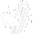
- FIG. 5 is a perspective view of a perpendicular connection feature 300 coupled to the bus bar 160.
- the connection feature 300 includes a base portion 302 that is positioned adjacent a face 304 of the bus bar 160.
- the connection feature 300 also includes a rectangular plate 306 that extends generally perpendicularly from the base 302, and, thus, extends generally perpendicularly from the bus bar 160.
- the connection feature 300 includes a set of holes 308 in the rectangular plate 306 that may be utilized to couple with a cable, another bus bar, a device, or the like.
- FIG. 5 also clearly illustrates a pair of small grooves or channels 330 positioned between the grooves 186.
- a number of these channels 330 may correspond to a particular characteristic of the bus bar 160.
- a base or rear portion 340 of the bus bar 160 that is positioned beneath the grooves 186 and opposite the face 304 of the bus bar 160 may be configurable during the extrusion process so that different thicknesses can be provided for different applications without changing the geometry of the grooves 186 and other characteristics of the bus bar 160 and/or system.
- the rear portion 340 can be expanded or reduced depending on the quantity of power that the bus bar 160 is configured to transmit without changing the size of the grooves 186 or the positioning of ridges 342 along opposite edges of the bus bar 160.
- This not only provides consistent groove geometry for coupling attachment features 116 with the bus bar 160 but constancy with regard to support features, such as the support brackets 162, for retaining the bus bar 160 within an enclosure.
- Different thicknesses of the bus bar 160 can provide different characteristics that it is desirable for a user to be able to readily discern. Since the expansion of the bus bar 160 is on a rear portion that may not be extremely visible to a user when installed, a number of the small channels 330 may be included on the face 304 of the bus bar 160 so that a user can simply observe the channels 330 on the face 304 and identify the nature of the installed bus bar 160. For example, a pair of channels may correspond to a high capacity bus bar and a single channel may correspond to a low capacity bus bar. Other characteristics of the bus bars may also be coordinated with the number of small channels extruded into the profile of each bus bar. It should be noted that embodiments include extruding the bur bar 160 with the identification channels 330 so that the characteristics of the bus bar 160 associated with the identification channels 330 can be easily identified from the time the bus bar 160 is extruded.
- FIG. 6 is a cross-sectional view of a bus bar 400 in accordance with present embodiments.
- the bus bar 400 includes a first groove 402 and a second groove 404, wherein each groove 402, 404 includes a narrow channel 406 extending from a face 408 of the bus bar 400 and an expanded cavity 410 further into the body of the bus bar 400.
- the width of the narrow channel 406 is indicated by reference numeral 420 and the width of the expanded cavity 410 is indicated by reference numeral 422.
- the difference in widths 420 and 422 forms lips 426 over the expanded cavity 410.
- the expanded cavity 410 is substantially wider than the narrow channel 406 to facilitate interlocking of attachment feature components with the grooves 402, 404 and engagement of the attachment feature components with the corresponding lips 426.
- the size of the lips 426 may vary depending on the ratio of the width of the channel 420 to the width of the cavity 422. In the illustrated embodiment, the ratio of the width of the channel to the width of the cavity is approximately 2:5. However, different ratios may be utilized in different embodiments.
- the grooves 402, 404 include a substantially T-shaped cross-section, in other embodiments different cross-sections may be included. For example, as illustrated by FIG.
- the bus bar 400 also includes a pair of ridges 460 that extend from opposite edges of the bus bar 400. In the illustrated embodiment, these ridges are offset from the front face 408 and a rear face 462 of the bus bar 400. However, in other embodiments, a front wall 464 of one or both ridges 460 may be flush with the front face 408 of the bus bar 400 while remaining offset from the rear face 462 of the bus bar 400.
- a thickness of the ridges 460 is indicated by reference numeral 466. This thickness 466 and a positioning of the ridges 460 relative to the front face 408 of the bus bar 400 may be consistently maintained for various bus bars with different capacities to facilitate cooperation with support features 116 and so forth.
- a rear portion 470 of the bus bar 400 may be expanded in certain embodiments to provide additional capacity while maintaining the same geometric relationship of the groove features and ridge features.
- FIG. 8 depicts a bus bar 500 with an expanded capacity relative to the bus bar 400 illustrated in FIG. 6 . While the bus bar 500 includes an expanded rear portion 502 relative to the rear portion 470 of bus bar 400, the geometric relationships between the groove features and ridges remain the same. Accordingly, while the bus bar 500 has additional capacity, it has the same functionality as the bus bar 400 with respect to attachment of connection features with the grooves 402, 404 and positioning the ridges 460 within a support bracket. Indeed, the attachment features will naturally cooperate in the same way with identical grooves. Further, as will be discussed in detail below, the cooperation with the support brackets in accordance with present embodiments does not substantially change.
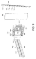
- FIG. 9 is a perspective view of a support bracket 600 exploded away from a bus bar 602 in accordance with present embodiments.
- the support bracket 600 comprises compression molded thermalset glass reinforced material that includes a main opening 604 with slots 606 on either side of the main opening 604.
- the slots 606 are sized to receive ridges 610 on either side of the bus bar 602.
- the main opening 604 has a height 612 that corresponds to a height 614 of a central portion of the bus bar 602 (excluding the added height of the ridges 610).
- the ridges 610 engage the slots 606 and prevent substantial rotation of the bus bar 602 about its lengthwise axis or movement in a direction traverse to its lengthwise axis.
- the engagement between the support bracket 600 and the bus bar 602 does permit lateral movement such that the bus bar 602 essentially floats within the bracket 600 without being fastened to the bracket 600, which facilitates attachment of other features to the bus bar 602.
- lateral movement is limited in accordance with present embodiments by end caps 620 that can be attached to the brackets 600 or by protective end pieces that are positioned on cabinet walls or other support features 622 adjacent the end of the bus bar 602.
- an end cap may be fastened on to the bracket 600 via engagement features molded into the bracket 600.
- the end cap and/or protective end piece coupled to the support 622 may still provide some lateral leeway.
- the main opening 604 in the illustrated bracket 600 includes a certain amount of tolerance in width relative to the illustrated bus bar 602.
- a certain amount of tolerance in width relative to the illustrated bus bar 602.
- front space 632 there is extra space provided between the vertical edge 626 of the bracket 600 and a front face 630 of the bus bar 160, which may be referred to as front space 632.
- rear space 640 there is also extra space provided between the vertical edge 634 of the bracket 600 and a rear face 636 of the bus bar 160, which may be referred to as rear space 640.
- This additional space is provided to enable flexibility with respect to increasing the capacity of the bus bar and adding length to the bus bar after manufacture.
- a bus bar with added capacity relative to the illustrated bus bar may include an expanded rear section.
- Such an expanded rear section can be accommodated by the rear space 640.
- a single bracket type can be manufactured to handle a wide variety of bus bars with differing capacities. This is cost efficient and reduces complexity.
- the front space 632 may be utilized to accommodate a splicing feature that joins the bus bar with another bus bar or with a conductive feature of an option bay.
- a bus bar can be extruded to essentially any length in accordance with present embodiments, it may be desirable to attach multiple bus bars together in series to communicate between bays and so forth. As illustrated in FIG.
- this may be achieved by placing a splice 650 within the front space 626 and coupling the splice 650 to both the bus bar 602 and a second bus bar 652.
- the splice 650 may be coupled to grooves 660 in the bus bars.
- the engagement features of the splice 650 may be slid through the ends of each bus bar 602, 652 and then tightened to retain the bus bars 602, 652 in position relative to one another.
- FIG. 12 is a process flow diagram of a method 800 of manufacturing and assembling a bus bar system in accordance with present embodiments.
- the process begins with extruding metal through a die of an extrusion system to form a bus bar, as represented by block 802.
- the extruder die may be configured to provide a bus bar with a body, a pair of ridges disposed along a length of the body such that they extend from opposite edges of the body, and at least a pair of grooves along the length of the body.
- the grooves extend into the body from a face of the body such that each of the grooves has a cross-section with a narrow passage extending from the face to a broadened cavity within the body.
- the procedure illustrate by block 802 may include adjusting the extruder die such that a portion of the body opposite the face of the body is extended or reduced to provide additional or less electrical transmission capacity, respectively, through the elongate metal extrusion. This may be done without changing the geometry of the ridges and/or grooves. Once such an extrusion system is set up with an appropriate die, bus bars with varying lengths and duplicated cross-sections can be manufactured very efficiently.
- the method 800 may also include assembling the bus bar within a bus support system.
- block 810 represents disposing the bus bar within a non-conductive support bracket such that the first and second ridges pass through slots on either side of a major opening in the bracket and the body is disposed within the major opening.
- the bracket can be coupled to an interior feature of an electrical enclosure such that the bus bar extends along the electrical enclosure, as represented by block 810.
- Non-conductive end caps or protective pieces may then be placed between the ends of the bus bar and the cabinet either by coupling such pieces to the bracket or the cabinet such that the bus bar can essentially float within the bracket without being directly fastened to the bracket, as represented by block 812.
Landscapes
- Engineering & Computer Science (AREA)
- Microelectronics & Electronic Packaging (AREA)
- Power Engineering (AREA)
- Patch Boards (AREA)
- Installation Of Bus-Bars (AREA)
Abstract
Description
- The present invention relates generally to the field of power electronic devices such as those used in power conversion or applying power to motors and similar loads. More particularly, the invention relates to an extruded electrical distribution bus and associated systems and methods.
- In the field of power electronic devices, a wide range of circuitry is known and currently available for transmitting, converting, producing, and applying power. Depending upon the application, such circuitry may transmit incoming power to various devices and/or convert incoming power from one form to another as needed by a load. In a typical drive system arrangement, for example, constant (or varying) frequency alternating current power (such as from a utility grid or generator) is converted to controlled frequency alternating current power to drive motors, and other loads. In this type of application, the frequency of the output power can be regulated to control the speed of the motor or other device. Further, drive system buses may transmit the power throughout the process. In a motor control center application, a bus system may facilitate transmission of power to a number of system components and devices. For example, a motor control center bus may be utilized to provide power to a drive system bus.
- Circuitry such as that detailed above may be employed with differing levels of incoming power for different load requirements. For example, power may be taken from a high voltage electrical grid and converted for use with a high horse power motor or the like. Alternatively, such circuitry may be utilized to simply distribute power to different devices via a motor control center bus. Circuitry for providing such functionality is often packaged together. Indeed, electrical systems with packaged electrical and electronic components, such as drive cabinets and motor control centers, are known and in use. For example, motor control centers (MCCs) are used for power and data distribution in large industrial operations, and drive cabinets are used for power conversion and distribution. In a typical MCC and/or drive cabinet a variety of components are housed in large electrical enclosures that may be subdivided into compartments. For example, an MCC may include components such as switchgear, semiconductor power electronic circuits, programmable logic controllers (PLCs), motor controllers, and so forth. A drive cabinet may include a rectifier (converter), an inverter, transitional attachments, and so forth. Further, such electrical enclosures may include bus work that communicatively couples the components with a power source and/or other components.
- Typically, an MCC or drive cabinet is connected to a main power line that provides three-phase AC power for transmission or conversion as needed by a particular load. Accordingly, the MCC or drive cabinet includes associated bus work, interconnections, and supporting structures for distribution of electrical power to the various components. Traditionally, such bus work is manufactured to a specific length with punched holes or a combination of cabling and bus work to provide for electrical transmission to components. Such bus work may be directly affixed to the cabinet by a fastener (e.g., a nut and bolt assembly) and a non-conductive standoff. Such bus work and attachment features can be complex, expensive, nonadjustable and/or difficult to configure. For example, traditional bus work may be generally cumbersome and only enable coupling of attachment features at specific locations on the bus (e.g., punched holes along the bus). Additionally, traditional bus systems and support structures require substantial changes to accommodate different amperage levels.
- Accordingly, it is now recognized that it would be desirable to develop a bus system that facilitates communicative coupling to high power drives and the like in a flexible configuration, enables simplified manufacturing changes to accommodate different amperage levels and cabinet arrangements, and enables convenient coupling of attachment features at generally any location along the bus.
- According to one embodiment of the present invention, an extruded high power electrical distribution bus is provided. Such a bus can be employed in an MCC, a drive cabinet, or any such electrical enclosure to facilitate transmission of power. A body of the bus includes an elongate metal extrusion with first and second ridges extending along a length of the body from opposite edges of the body. Further, the bus includes a first groove and a second groove extending along the length of the body and into the body from a face of the body. Each of the first and second grooves comprises a cross-section having a narrow passage extending from the face into a broader cavity within the body, such as a T-shaped or L-shaped groove cross-section. Additionally, the bus includes machined openings into each groove, wherein each of the machined openings is wider than the width of the corresponding groove to which it provides access.
- Present embodiments may include a method, such as an extrusion process, for forming an elongate metal extrusion that includes a first ridge and a second ridge extending along a length of a body from opposite edges of the body, and a first groove and a second groove positioned along the length of the body and extending into the body from a face of the body. The extrusion process utilizes an extrusion die that generates the first and second grooves within the body such that a cross-section of each groove includes a narrow passage extending from a face of the body into a broadened cavity within the body. The method may also include a machining process for providing openings into the grooves such that the grooves can accommodate insertion of an attachment feature having an enlarged distill end and a narrowed neck. Once inserted into the first groove or the second groove, the attachment feature can slide along the groove into which it was inserted and engage the enlarged distill end with the broader cavity and engage the narrowed neck with the narrow passage.
- These and other features, aspects, and advantages of the present invention will become better understood when the following detailed description is read with reference to the accompanying drawings in which like characters represent like parts throughout the drawings, wherein:
-
FIG. 1 is a front view of an electrical enclosure including a bus system in accordance with present embodiments; -
FIG. 2 is a block diagram of a pair of drive systems utilizing a bus system in accordance with present embodiments; -
FIG. 3 is a perspective view of a bus bar that is retained by a pair of support brackets and coupled to a pair of attachment features in accordance with present embodiments; -
FIG. 4 is a perspective view of a bus system disposed within an enclosure in accordance with present embodiments; -
FIG. 5 is a perspective view of a perpendicular connection feature coupled to a bus bar in accordance with present embodiments; -
FIG. 6 is a cross-sectional view of a bus bar in accordance with present embodiments; -
FIG. 7 illustrates various cross-sectional views of a bus bar with different groove cross-sections in accordance with present embodiments; -
FIG. 8 depicts a bus bar that has been extruded with an enlarged rear portion to provide expanded capacity relative to the bus bar illustrated inFIG. 6 in accordance with present embodiments; -
FIG. 9 is a perspective view of a support bracket exploded away from a bus bar in accordance with present embodiments; -
FIG. 10 is a cross-sectional view of a bus bar inserted into a bracket support in accordance with present embodiments; -
FIG. 11 is a perspective view of a splicing feature coupling a pair of bus bars in accordance with present embodiments; and -
FIG. 12 is a process flow diagram of a method for producing a bus bar system in accordance with present embodiments. - As discussed in detail below, embodiments of the present technique function to provide a bus system that facilitates flexible configuration and connection of components to a bus bar within an electrical enclosure, such as an MCC or drive cabinet. In particular, the present technique provides an extruded bus bar, attachment features and support features for the bus bar, wherein the bus bar includes ridges extending from opposite edges of a body of the bus bar and at least a pair of grooves disposed in a face of the bus bar. A support feature includes an insulated bracket that receives the bus bar into a receptacle and allows the bus bar to essentially float within the receptacle without rigid attachment.
- References in the specification to "one embodiment," "an embodiment," or "an exemplary embodiment," indicate that the embodiment described may include a particular feature, structure, or characteristic, but every embodiment may not necessarily include the particular feature, structure, or characteristic. Moreover, such phrases are not necessarily referring to the same embodiment. Further, when a particular feature, structure, or characteristic is described in connection with an embodiment, it is submitted that it is within the knowledge of one skilled in the art to affect such feature, structure, or characteristic in connection with other embodiments whether or not explicitly described.
- Turning now to the drawings and referring to
FIG. 1 , anelectrical enclosure 100 is illustrated in which electrical components of various types may be housed and connected via a bus system that includes bus bars, connection features, and a support system. Theenclosure 100 may be representative of a motor control center or other industrial, commercial, or marine electrical system. In general, theenclosure 100 provides a protective shell around various electrical components and the bus system. For example, theenclosure 100 may include ashell 102 made of any suitable material, such as heavy gauge sheet metal, reinforced plastic, and so forth. Further, theenclosure 100 may include devices such as a programmable logic controller, switches, motor controls, inverters, rectifiers, and so forth disposed along and/or coupled with the bus system. Specifically, in the illustrated embodiment, theenclosure 100 includes awiring bay section 106 positioned between a pair ofpower drive sections - A set of
bus bars 112 passes along a back wall of theenclosure 100 and through each of the enclosure sections (i.e., thewiring bay section 106 and each of thedrive sections 108, 110). A pair of ground bars 114 also passes through the enclosure sections. The bus bars 112 are made of conductive material (e.g., copper or aluminum) that has been extruded to a desired length for use with theenclosure 100. Additionally, as will be discussed in detail below, the bus bars 112 are extruded with certain cross-sectional features that facilitate communicatively coupling the bus bars 112 with expansion or attachments features 116 and devices. These cross-sectional features also facilitate cooperation with a support system that couples the bus bars 112 to theenclosure 100 and provides flexibility in configuration of the bus system (e.g., expansion of bus bar capacity) without requiring substantial changes in the bus system. Indeed, each of the bus bars 112 is held in place within theenclosure 100 with a support system that includes bus support brackets that are formed or molded from a thermalset glass reinforced material or a non-conductive material to coordinate with aspects of the cross-sectional features. Specifically, as will be discussed in further detail below, the support brackets each include openings into which one of the bus bars 112 can slide. Each support bracket includes a main opening with slots that correspond to cross-sectional features of the bus bars 112 such that the bus bars 112 can be retained without being fastened to the brackets. In some embodiments, end caps or the like may be positioned near or around the ends of the bus bars 112 such that the bus bars 112 can essentially float within the brackets without substantial lateral sliding. - During operation of the illustrated embodiment, the set of
bus bars 112 receives power and transmits the power to various components within theenclosure 100. An upper threebus bars 118, a middle twobus bars 120, and a lower threebus bars 122 of the set ofbus bars 112 may each perform a different function. Specifically, as illustrated by the block diagram inFIG. 2 , the bus bars 112 function to provide three-phase AC power from anelectrical grid 140 to drivesystems 142 of thedrive sections grid 140 to a level that is desirable for aparticular load 144, such as a motor. That is, the bus bars 112 function to transmit power to thedrive systems 142 at a voltage and frequency of thegrid 140, transmit power within thedrive systems 142 as direct current, and transmit power out of thedrive systems 142 to theload 144 at a desired voltage and frequency for theload 144. - Specifically, the upper three
bus bars 118, which may be referred to as line bus bars 118, are coupled to thepower supply grid 140 and a rectifier orconverter 148 of each drive system so that three-phase AC power from thegrid 140 is provided to thedrive systems 142. In some embodiments, the three-phase AC power from thegrid 140 may also be provided to other components within or related to theenclosure 100, such as an MCC bus and devices along the MCC bus. Once the three-phase AC power is provided to the rectifier orconverter 148 within each of thepower drive sections rectifiers 148 convert the three-phase AC power to DC power, which is then transmitted to aninverter 150 in each of thepower drive sections bus bars 120 may be referred to as DC bus bars 120. Theinverters 150 receive the DC power from the DC bus bars 120 and convert it to three-phase AC power that is appropriate for theload 144 via inverter circuitry, which typically includes several high power switches, such as a drive circuit and insulated-gate bipolar transistors (IGBTs). This output power is then provided to the load via the lower threebus bars 122, which may be referred to as load bus bars 122. - As set forth above, the bus bars 112 provide power to various different components of the
drive systems 142 and other features. This is achieved, in accordance with present embodiments, by communicatively coupling the various devices to the bus bars 112 via attachment or connection features 116. The connection features 116 interlock with grooves in the bus bars 112 via bus clamps or the like. Due to the nature of the grooves in the bus bars 112, the connection features 116 can generally slide along the bus bars 112 and secure to any location along the bus bars 112 such that the connection features 116 can easily be positioned for connection with a device, power source, or the like. Indeed, the connection features 116 may also couple directly to devices and/or couple with cabling or the like that in turn couples with the devices. This facilitates power transmission between the bus bars 112 and other electrical features via the connection features 116. For example, each of the line bus bars 118 is coupled with thegrid 140 via one of the connection features 116 and a cable that interconnects with both theattachment connection feature 116 and grid wiring. Various types of attachment or connection features 116 will be discussed in further detail below. -
FIG. 3 is a perspective view of abus bar 160 that is retained by a pair ofsupport brackets 162 and coupled to a pair of attachment features 116 in accordance with present embodiments. Thebus bar 160 is extruded metal and can be extruded to a desired length for its application. Thebus bar 160 is also extruded such that it includes particular cross-sectional characteristics that facilitate operation in accordance with present embodiments. Further, different metals may be used to provide different functionality. For example, depending on the level of power being transmitted, thebus bar 160 may be extruded from aluminum or copper. - With regard to the support features, the
bus bar 160 is shown disposed within moldedbrackets 162 that are formed (e.g., molded) from non-conductive material. Thebrackets 162 are configured to slidably receive thebus bar 160 into a receptacle disposed within the bracket and to attach with an enclosure (e.g., the enclosure 100) or other support features. As can be seen inFIG. 3 , thesupport brackets 162 do not necessarily couple directly to thebus bar 160 but engage with cross-sectional features 164 (e.g., ridges) of thebus bar 160 to prevent rotation or movement in certain directions, while allowing thebus bar 160 to float laterally. Thebrackets 162 also include features that can accommodate adjustments to thebus bar 160, as will be discussed in further detail below. - With regard to the features coupled to the
bus bar 160, the illustrated attachment features 116 include aside bus 166 that functions as a perpendicular extension of thebus bar 160 and acable attachment 168 that functions to communicatively couple thebus bar 160 with acable 170. Specifically, theside bus 166 includes a pair ofbrackets 172 disposed at each end of anangled extension 174, which is generally a parallelepiped. Theside bus 166 may enable communicative coupling between thebus bar 160 and a power core or the like. Thecable attachment 168 includes anangled bracket 180 with coupling features 182 for attaching to thebracket 180 and thecable 170. Thecable attachment 168 may facilitate communicative coupling between thebus bar 160 and a power grid or the like. - As an example,
FIG. 4 includes a perspective view of abus system 200 disposed within anenclosure 100 in accordance with present embodiments. Thebus system 200 includesvarious bus bars 202, attachment features 204, and support features 206. The arrangement of features inFIG. 4 demonstrates aspects of the flexibility of present embodiments. For example, each of the bus bars 202 is capable of making multiple connections to the attachment features 204 at essentially any location along the bus bars 202. Specifically, for example, the lowermost bus bar 208 inFIG. 4 is coupled to multiple attachments including a side bus and a cable attachment. The arrangement of the bus bars 202 in the cabinet and the use of coupling features 204, such as the cable attachments, illustrate the accessibility of present embodiments. For example, connections may be brought into and/or out of the cabinet from a top or bottom of the cabinet and coupled with one of the bus bars 202 via an attachment feature that can be positioned anywhere along one of the bus bars 202. Additionally, due to the nature of the bus bars 202 and associated attachments, connections can essentially come from any direction. Specifically, for example, power could be provided via a cable that passes through a bottom or top of the cabinet and attaches to the lowermost oruppermost bus bar 202 via a cable attachment coupled to thebus bar 202.FIG. 4 also illustrates the flexibility of a support system in accordance with present embodiments. For example, the side buses are coupled to support features 206, which not only support the side buses but also provide support for the bus bars 202 via the attachment to the side busses. - Returning to
FIG. 3 , each of the illustrated attachment features 116 is configured to couple withgrooves 186 in thebus bar 160. Thegrooves 186 have a cross-section that includes anarrow channel 188 with an expandedcavity 190. Thus, thegrooves 186 can slideably receive a component of the attachment features 116 with a narrow neck and an expanded distill end. In other words, a component of an attachment feature including a narrow neck and an expanded distill end can slide along one of thegrooves 186 when the narrow neck is positioned within thenarrow channel 188 and the expanded distill end is positioned within the expandedcavity 190. For example, in the illustrated embodiment, thecable attachment 168 includes a pair ofbolts 192 that pass through the bracket orbody 180 of thecable attachment 168 and into thegrooves 186. Thebolts 192 are each coupled or integral with separate plate features 194 that are slideably positioned within the expandedcavity 190 of thecorresponding grooves 186. The plate features 194 may be inserted into thecorresponding grooves 186 at an end of the bus bars 160 or viaopenings 196 that are machined into each of thegrooves 186. By positioning thebolts 192 andplates 196 within thegrooves 186 in this manner,nuts 198 can be tightened onto each of thebolts 192 such that the plate features 194 are pulled against an inner lip of eachgroove 186. Thus, thecable attachment feature 168 is securely fastened to thebus bar 160. -
Multiple grooves 186 are employed in the face of thebus bar 160 to reduce moment of the attachment features 116 about thebus bar 160 and to facilitate uniform contact between thebus bar 160 and the attachment features 116. Indeed, in accordance with present embodiments, the torque present when thebus bar 160 is coupled with the attachment features 116 facilitates the provision of communicative contact between thebus bar 160 and the attachment features 116. It should be noted that while twogrooves 186 are provided in the embodiment illustrated byFIG. 3 , in other embodiments, additional grooves may be included. -
FIG. 5 is a perspective view of aperpendicular connection feature 300 coupled to thebus bar 160. Theconnection feature 300 includes abase portion 302 that is positioned adjacent aface 304 of thebus bar 160. Theconnection feature 300 also includes arectangular plate 306 that extends generally perpendicularly from thebase 302, and, thus, extends generally perpendicularly from thebus bar 160. Theconnection feature 300 includes a set ofholes 308 in therectangular plate 306 that may be utilized to couple with a cable, another bus bar, a device, or the like. As with previously described attachment features 116, theperpendicular connection feature 300 couples to thebus bar 160 viafasteners 310 that include a portions that extend through thenarrow channels 188 of thegrooves 186 and into the expandedcavities 190 of the grooves such that they slideably engage thegrooves 186. This sliding engagement facilitates connection of components with thebus bar 160 at any location on thebus bar 160 without added hardware or support. Additionally, the attachment features 116 coordinate with thegrooves 186 to enable tightening aboutlips 312 of eachgroove 186 that extend toward thenarrow channel 188 and over the expandedcavity 190 of eachgroove 186. In the illustrated embodiment, thefasteners 310 are bus clamps that include nuts 320 that tighten about abolt 322 to press thebase portion 302 against thelips 312 of eachgroove 186 by drawing in a plate or other expanded distill end (not shown) of thebolt 322 positioned within the expandedcavity 190 of thegroove 186. -
FIG. 5 also clearly illustrates a pair of small grooves orchannels 330 positioned between thegrooves 186. A number of thesechannels 330 may correspond to a particular characteristic of thebus bar 160. For example, it may be desirable to provide thechannels 330 as a readily accessible indication of the capacity of thebus bar 160. Indeed, in accordance with present embodiments, a base orrear portion 340 of thebus bar 160 that is positioned beneath thegrooves 186 and opposite theface 304 of thebus bar 160 may be configurable during the extrusion process so that different thicknesses can be provided for different applications without changing the geometry of thegrooves 186 and other characteristics of thebus bar 160 and/or system. For example, therear portion 340 can be expanded or reduced depending on the quantity of power that thebus bar 160 is configured to transmit without changing the size of thegrooves 186 or the positioning ofridges 342 along opposite edges of thebus bar 160. This not only provides consistent groove geometry for coupling attachment features 116 with thebus bar 160 but constancy with regard to support features, such as thesupport brackets 162, for retaining thebus bar 160 within an enclosure. - Different thicknesses of the
bus bar 160 can provide different characteristics that it is desirable for a user to be able to readily discern. Since the expansion of thebus bar 160 is on a rear portion that may not be extremely visible to a user when installed, a number of thesmall channels 330 may be included on theface 304 of thebus bar 160 so that a user can simply observe thechannels 330 on theface 304 and identify the nature of the installedbus bar 160. For example, a pair of channels may correspond to a high capacity bus bar and a single channel may correspond to a low capacity bus bar. Other characteristics of the bus bars may also be coordinated with the number of small channels extruded into the profile of each bus bar. It should be noted that embodiments include extruding thebur bar 160 with theidentification channels 330 so that the characteristics of thebus bar 160 associated with theidentification channels 330 can be easily identified from the time thebus bar 160 is extruded. -
FIG. 6 is a cross-sectional view of abus bar 400 in accordance with present embodiments. As with previously discussed embodiments, thebus bar 400 includes afirst groove 402 and asecond groove 404, wherein eachgroove narrow channel 406 extending from aface 408 of thebus bar 400 and an expandedcavity 410 further into the body of thebus bar 400. The width of thenarrow channel 406 is indicated byreference numeral 420 and the width of the expandedcavity 410 is indicated byreference numeral 422. The difference inwidths forms lips 426 over the expandedcavity 410. Indeed, the expandedcavity 410 is substantially wider than thenarrow channel 406 to facilitate interlocking of attachment feature components with thegrooves lips 426. The size of thelips 426 may vary depending on the ratio of the width of thechannel 420 to the width of thecavity 422. In the illustrated embodiment, the ratio of the width of the channel to the width of the cavity is approximately 2:5. However, different ratios may be utilized in different embodiments. Additionally, while in the illustrated embodiment, thegrooves FIG. 7 , thebus bar 400 can include grooves with L-shapedcross-sections 450, Y-shapedcross-sections 452, triangular-shapedcross-sections 454, hook-shapedcross-sections 456, or a combination of such cross sections. Indeed, any of various cross-sections with a narrow entry point and a broadened cavity may be extruded into thebus bar 400. Having a symmetrical cross-section may be beneficial because it functions in the same manner regardless of whichgroove - Turning back to
FIG. 6 , thebus bar 400 also includes a pair ofridges 460 that extend from opposite edges of thebus bar 400. In the illustrated embodiment, these ridges are offset from thefront face 408 and arear face 462 of thebus bar 400. However, in other embodiments, afront wall 464 of one or bothridges 460 may be flush with thefront face 408 of thebus bar 400 while remaining offset from therear face 462 of thebus bar 400. A thickness of theridges 460 is indicated byreference numeral 466. Thisthickness 466 and a positioning of theridges 460 relative to thefront face 408 of thebus bar 400 may be consistently maintained for various bus bars with different capacities to facilitate cooperation with support features 116 and so forth. - As briefly discussed above, a
rear portion 470 of thebus bar 400 may be expanded in certain embodiments to provide additional capacity while maintaining the same geometric relationship of the groove features and ridge features. For example,FIG. 8 depicts abus bar 500 with an expanded capacity relative to thebus bar 400 illustrated inFIG. 6 . While thebus bar 500 includes an expandedrear portion 502 relative to therear portion 470 ofbus bar 400, the geometric relationships between the groove features and ridges remain the same. Accordingly, while thebus bar 500 has additional capacity, it has the same functionality as thebus bar 400 with respect to attachment of connection features with thegrooves ridges 460 within a support bracket. Indeed, the attachment features will naturally cooperate in the same way with identical grooves. Further, as will be discussed in detail below, the cooperation with the support brackets in accordance with present embodiments does not substantially change. -
FIG. 9 is a perspective view of asupport bracket 600 exploded away from abus bar 602 in accordance with present embodiments. In the illustrated embodiment, thesupport bracket 600 comprises compression molded thermalset glass reinforced material that includes amain opening 604 withslots 606 on either side of themain opening 604. Theslots 606 are sized to receiveridges 610 on either side of thebus bar 602. Further, themain opening 604 has aheight 612 that corresponds to aheight 614 of a central portion of the bus bar 602 (excluding the added height of the ridges 610). Accordingly, when thebus bar 602 is positioned within thesupport bracket 600, theridges 610 engage theslots 606 and prevent substantial rotation of thebus bar 602 about its lengthwise axis or movement in a direction traverse to its lengthwise axis. However, the engagement between thesupport bracket 600 and thebus bar 602 does permit lateral movement such that thebus bar 602 essentially floats within thebracket 600 without being fastened to thebracket 600, which facilitates attachment of other features to thebus bar 602. In should be noted that lateral movement is limited in accordance with present embodiments byend caps 620 that can be attached to thebrackets 600 or by protective end pieces that are positioned on cabinet walls or other support features 622 adjacent the end of thebus bar 602. For example, an end cap may be fastened on to thebracket 600 via engagement features molded into thebracket 600. The end cap and/or protective end piece coupled to thesupport 622 may still provide some lateral leeway. - The
main opening 604 in the illustratedbracket 600 includes a certain amount of tolerance in width relative to the illustratedbus bar 602. For example, as can be seen in the cross-sectional view illustrated byFIG. 10 , when thebus bar 602 is inserted into thebracket 600, there is extra space provided between thevertical edge 626 of thebracket 600 and afront face 630 of thebus bar 160, which may be referred to asfront space 632. There is also extra space provided between thevertical edge 634 of thebracket 600 and arear face 636 of thebus bar 160, which may be referred to asrear space 640. This additional space, with respect to the illustrated embodiment, is provided to enable flexibility with respect to increasing the capacity of the bus bar and adding length to the bus bar after manufacture. For example, as discussed above, a bus bar with added capacity relative to the illustrated bus bar may include an expanded rear section. Such an expanded rear section can be accommodated by therear space 640. Thus, a single bracket type can be manufactured to handle a wide variety of bus bars with differing capacities. This is cost efficient and reduces complexity. Further, thefront space 632 may be utilized to accommodate a splicing feature that joins the bus bar with another bus bar or with a conductive feature of an option bay. Indeed, while a bus bar can be extruded to essentially any length in accordance with present embodiments, it may be desirable to attach multiple bus bars together in series to communicate between bays and so forth. As illustrated inFIG. 11 , this may be achieved by placing asplice 650 within thefront space 626 and coupling thesplice 650 to both thebus bar 602 and asecond bus bar 652. As with other attachment features, thesplice 650 may be coupled togrooves 660 in the bus bars. Specifically, the engagement features of thesplice 650 may be slid through the ends of eachbus bar - The
bracket 600 also includes mounting features 700 that facilitate tool-free coupling with an enclosure or support feature, such as thesupport feature 622. Indeed, in the illustrated embodiment, the mounting features 700 include tabs that can be passed throughslots 702 in thesupport feature 622. In some embodiments, the dimensions of the mounting features 700 and theslots 702 may be such that a snap fit is obtained. Further, certaintopographic features 704 on a face of thebracket 600 interlock with extensions or indentations within thesupport feature 622, such asindentation 708. Such features of thebracket 600 and thesupport feature 622 allow an installer to position thebracket 600 in a desired location without separate fasteners. Further, the mounting feature 700 cooperates with the other features so that thebracket 600 is held in place (hands free) while separate fasteners (e.g., screws) are passed through holes 710 in thebracket 600 andholes 712 in thesupport feature 622. Thus, present embodiments provide users with the tools to efficiently secure a bus system within an enclosure. -
FIG. 12 is a process flow diagram of amethod 800 of manufacturing and assembling a bus bar system in accordance with present embodiments. The process begins with extruding metal through a die of an extrusion system to form a bus bar, as represented byblock 802. The extruder die may be configured to provide a bus bar with a body, a pair of ridges disposed along a length of the body such that they extend from opposite edges of the body, and at least a pair of grooves along the length of the body. The grooves extend into the body from a face of the body such that each of the grooves has a cross-section with a narrow passage extending from the face to a broadened cavity within the body. The procedure illustrate byblock 802 may include adjusting the extruder die such that a portion of the body opposite the face of the body is extended or reduced to provide additional or less electrical transmission capacity, respectively, through the elongate metal extrusion. This may be done without changing the geometry of the ridges and/or grooves. Once such an extrusion system is set up with an appropriate die, bus bars with varying lengths and duplicated cross-sections can be manufactured very efficiently. - Once the bus bar is extruded, as represented by
block 802, the bus bar is cut to a desired length, as represented byblock 804. Further, the bus bar may be machined to remove excess material and to provide additional features. For example, block 806 represents machining an opening into each groove such that each machined opening is configured to accommodate insertion of an attachment feature having an enlarged distill end and a narrowed neck. The method may also include inserting an attachment feature into one of the grooves (e.g., via the machined opening) so that the attachment feature can slide along the groove, as represented byblock 808. - The
method 800 may also include assembling the bus bar within a bus support system. For example, block 810 represents disposing the bus bar within a non-conductive support bracket such that the first and second ridges pass through slots on either side of a major opening in the bracket and the body is disposed within the major opening. Further, the bracket can be coupled to an interior feature of an electrical enclosure such that the bus bar extends along the electrical enclosure, as represented byblock 810. Non-conductive end caps or protective pieces may then be placed between the ends of the bus bar and the cabinet either by coupling such pieces to the bracket or the cabinet such that the bus bar can essentially float within the bracket without being directly fastened to the bracket, as represented byblock 812. - While only certain features of the invention have been illustrated and described herein, many modifications and changes will occur to those skilled in the art. It is, therefore, to be understood that the appended claims are intended to cover all such modifications and changes as fall within the true spirit of the invention.
The following is a list of further preferred embodiments of the invention: - Embodiment 1: An electrical distribution bus system, comprising:
- an elongate metal body;
- a first groove and a second groove along the length of the body and extending into the body from a face of the body such that each of the first and second grooves comprises a cross-section having a narrow passage extending from the face into a broader cavity within the body; and
- an opening into each of the first groove and the second groove, wherein each opening is wider than each corresponding groove in a direction traverse to the length of each groove.
- Embodiment 2: The system of embodiment 1, wherein the first and/or second groove comprises a T-shaped, Y-shaped, triangular-shaped, or L-shaped cross-section.
- Embodiment 3: The system of embodiment 1, wherein the cross-section of the first and/or second groove is configured to accommodate insertion of an attachment feature having an enlarged distal end and a narrowed neck such that, once inserted into the first groove or the second groove, the attachment feature can slide along the groove into which the attachment feature was inserted, engage the enlarged distal end with the broader cavity, and engage the narrowed neck with the narrow passage.
- Embodiment 4: The system of embodiment 1, wherein a ratio of the width of the narrow passage to the width of the broader cavity of the first and/or second groove is approximately 10:15.
- Embodiment 5: The system of embodiment 1, wherein the elongate metal body comprises extruded copper or aluminum.
- Embodiment 6: The system of embodiment 1, comprising a side bus coupled to the body via side bus couplings engaged with the first and second grooves such that the side bus is in electrical communication with the body and extends substantially perpendicularly from the body.
- Embodiment 7: The system of embodiment 1, comprising an additional elongate metal body coupled with the elongate metal body via a splice.
- Embodiment 8: The system of embodiment 7, comprising a support bracket disposed around the splice, the bracket comprising a non-conductive material having slots on either side of a major opening, wherein the slots are configured to engage a pair of ridges along a length of the body, wherein each ridge extends from an opposite edge of the body.
- Embodiment 9: The system of embodiment 8, wherein the major opening is configured to accommodate a thickness of the body and the splice, wherein the splice is coupled to the first and/or second grooves on the face of the body.
- Embodiment 10: The system of embodiment 1, comprising a non-conductive support bracket disposed about the body, first and second ridges extending from either side of the body passing through slots on either side of a major opening in the bracket to support the body within the major opening.
- Embodiment 11: The system of embodiment 1, comprising one or more shallow grooves disposed between the first groove and the second groove and corresponding to a thickness and/or metal type of the elongate metal extrusion to facilitate identification of the conductive capabilities of the extruded high power electrical distribution bus.
- Embodiment 12: The system of embodiment 11, wherein a number of shallow grooves correlates to the thickness of the elongate metal extrusion.
- Embodiment 13: A method of manufacturing an electrical distribution bus system, comprising:
- extruding an elongate metal extrusion that comprises:
- a body; and
- a first groove and a second groove along the length of the body that each extend into the body from a face of the body such that each of the first and second grooves comprises a cross-section having a narrow passage extending from the face to a broadened cavity within the body.
- extruding an elongate metal extrusion that comprises:
- Embodiment 14: The method of embodiment 13, comprising forming an opening into each of the first groove and the second groove such that each opening is configured to accommodate insertion of an attachment feature having an enlarged distal end and a narrowed neck such that, once inserted into the first groove or the second groove, the attachment feature can slide along the groove into which it was inserted and engage the enlarged distal end with the broader cavity and engage the narrowed neck with the narrow passage.
- Embodiment 15: The method of embodiment 13, comprising forming a portion of the body opposite the face of the body that is extended or reduced to provide additional or less electrical transmission capacity, respectively.
- Embodiment 16: The method of embodiment 15, comprising maintaining a fixed geometric relationship between the first groove and the second groove regardless of whether the body is extended or reduced.
- Embodiment 17: The method of embodiment 13, comprising disposing the elongate metal extrusion within a non-conductive support bracket such that the first and second ridges pass through slots on either side of a major opening in the bracket and the body is disposed within the major opening.
- Embodiment 18: The method of embodiment 17, comprising coupling the bracket to an interior feature of an electrical enclosure such that the elongate metal extrusion extends along the electrical enclosure.
- Embodiment 19: The method of embodiment 18, comprising placing non-conductive components between sides of the electrical enclosure and ends of the elongate metal extrusion such that the elongate metal extrusion can slide within the bracket and touch the non-conductive components.
- Embodiment 20: The method of embodiment 17, comprising disposing the elongate metal extrusion within the non-conductive bracket without otherwise coupling the elongate metal extrusion to the bracket.
- Embodiment 21: The method of embodiment 13, wherein a the elongate metal extrusion comprises a first ridge and a second ridge along a length of the body, wherein the first and second ridges extend from opposite edges of the body.
- Embodiment 22: A system for providing an electrical power distribution comprising:
- an enclosure;
- three input buses disposed in the enclosure and configured to receive three-phase AC power;
- a converter coupled to the input busses for receiving the three-phase AC power from the input buses and converting the three-phase AC power into DC power;
- a pair of DC conductors coupled to the converter for transmitting the DC power;
- an inverter coupled to the DC conductors for receiving the DC power and converting the DC power to a desired AC power sufficient to drive the load;
- three output buses coupled to the inverter for transmitting the desired AC power to the load;
- wherein the input buses and output buses each comprise an elongate metal extrusion comprising a first groove and a second groove positioned along the length of a body and extending into the body from a face of the body such that each of the first and second grooves comprises a cross-section having a narrow passage extending from the face into a broadened cavity within the body.
- Embodiment 23: The system of embodiment 22, comprising an attachment feature capable of being inserted into an opening into each of the first groove and the second groove of a one of the buses, wherein the attachment feature comprises an enlarged distal end and a narrowed neck such that, once inserted into the first groove or the second groove, the attachment feature can slide along the groove into which it was inserted and engage the enlarged distal end with the broadened cavity and engage the narrowed neck with the narrow passage.
- Embodiment 24: The system of embodiment 22, comprising insulative supports secured to the enclosure and receiving the input buses and the output buses to support the input buses and the output buses in the enclosure.
- Embodiment 25: The system of embodiment 24, wherein the insulative supports comprise openings that receive the input buses and the output buses in a floating manner.
- Embodiment 26: The system of embodiment 22, wherein the DC conductors comprises bus members substantially identical to the input and output buses.
Claims (15)
- An electrical distribution bus system, comprising:an elongate metal body;a first groove and a second groove along the length of the body and extending into the body from a face of the body such that each of the first and second grooves comprises a cross-section having a narrow passage extending from the face into a broader cavity within the body; andan opening into each of the first groove and the second groove, wherein each opening is wider than each corresponding groove in a direction traverse to the length of each groove.
- The system of claim 1, wherein the first and/or second groove comprises a T-shaped, Y-shaped, triangular-shaped, or L-shaped cross-section.
- The system of claim 1 or 2, wherein the cross-section of the first and/or second groove is configured to accommodate insertion of an attachment feature having an enlarged distal end and a narrowed neck such that, once inserted into the first groove or the second groove, the attachment feature can slide along the groove into which the attachment feature was inserted, engage the enlarged distal end with the broader cavity, and engage the narrowed neck with the narrow passage.
- The system of any one of claims 1 to 3, wherein a ratio of the width of the narrow passage to the width of the broader cavity of the first and/or second groove is approximately 10:15, or
wherein the elongate metal body comprises extruded copper or aluminum, or
comprising a side bus coupled to the body via side bus couplings engaged with the first and second grooves such that the side bus is in electrical communication with the body and extends substantially perpendicularly from the body. - The system of any one of claims 1 to 4, comprising an additional elongate metal body coupled with the elongate metal body via a splice, and/or
comprising a support bracket disposed around the splice, the bracket comprising a non-conductive material having slots on either side of a major opening, wherein the slots are configured to engage a pair of ridges along a length of the body, wherein each ridge extends from an opposite edge of the body, and/or
wherein the major opening is configured to accommodate a thickness of the body and the splice, wherein the splice is coupled to the first and/or second grooves on the face of the body. - The system of any one of claims 1 to 5, comprising a non-conductive support bracket disposed about the body, first and second ridges extending from either side of the body passing through slots on either side of a major opening in the bracket to support the body within the major opening.
- The system of any one of claims 1 to 6, comprising one or more shallow grooves disposed between the first groove and the second groove and corresponding to a thickness and/or metal type of the elongate metal extrusion to facilitate identification of the conductive capabilities of the extruded high power electrical distribution bus, and/or wherein a number of shallow grooves correlates to the thickness of the elongate metal extrusion.
- A method of manufacturing an electrical distribution bus system, comprising:extruding an elongate metal extrusion that comprises:a body; anda first groove and a second groove along the length of the body that each extend into the body from a face of the body such that each of the first and second grooves comprises a cross-section having a narrow passage extending from the face to a broadened cavity within the body.
- The method of claim 8, comprising forming an opening into each of the first groove and the second groove such that each opening is configured to accommodate insertion of an attachment feature having an enlarged distal end and a narrowed neck such that, once inserted into the first groove or the second groove, the attachment feature can slide along the groove into which it was inserted and engage the enlarged distal end with the broader cavity and engage the narrowed neck with the narrow passage.
- The method of claim 8, comprising forming a portion of the body opposite the face of the body that is extended or reduced to provide additional or less electrical transmission capacity, respectively, and/or
comprising maintaining a fixed geometric relationship between the first groove and the second groove regardless of whether the body is extended or reduced. - The method of claim 8, comprising disposing the elongate metal extrusion within a non-conductive support bracket such that the first and second ridges pass through slots on either side of a major opening in the bracket and the body is disposed within the major opening.
- The method of claim 11, comprising coupling the bracket to an interior feature of an electrical enclosure such that the elongate metal extrusion extends along the electrical enclosure, and/or
comprising placing non-conductive components between sides of the electrical enclosure and ends of the elongate metal extrusion such that the elongate metal extrusion can slide within the bracket and touch the non-conductive components, or
comprising disposing the elongate metal extrusion within the non-conductive bracket without otherwise coupling the elongate metal extrusion to the bracket. - The method of any one of claims 8 to 12, wherein a the elongate metal extrusion comprises a first ridge and a second ridge along a length of the body, wherein the first and second ridges extend from opposite edges of the body.
- A system for providing an electrical power distribution comprising:an enclosure;three input buses disposed in the enclosure and configured to receive three-phase AC power;a converter coupled to the input busses for receiving the three-phase AC power from the input buses and converting the three-phase AC power into DC power;a pair of DC conductors coupled to the converter for transmitting the DC power;an inverter coupled to the DC conductors for receiving the DC power and converting the DC power to a desired AC power sufficient to drive the load;three output buses coupled to the inverter for transmitting the desired AC power to the load;wherein the input buses and output buses each comprise an elongate metal extrusion comprising a first groove and a second groove positioned along the length of a body andextending into the body from a face of the body such that each of the first and second grooves comprises a cross-section having a narrow passage extending from the face into a broadened cavity within the body.
- The system of claim 14, comprising an attachment feature capable of being inserted into an opening into each of the first groove and the second groove of a one of the buses, wherein the attachment feature comprises an enlarged distal end and a narrowed neck such that, once inserted into the first groove or the second groove, the attachment feature can slide along the groove into which it was inserted and engage the enlarged distal end with the broadened cavity and engage the narrowed neck with the narrow passage, or
comprising insulative supports secured to the enclosure and receiving the input buses and the output buses to support the input buses and the output buses in the enclosure, and/or
wherein the insulative supports comprise openings that receive the input buses and the output buses in a floating manner, or
wherein the DC conductors comprises bus members substantially identical to the input and output buses.
Applications Claiming Priority (1)
| Application Number | Priority Date | Filing Date | Title |
|---|---|---|---|
| US12/837,670 US8289680B2 (en) | 2010-07-16 | 2010-07-16 | Power bus system and method |
Publications (3)
| Publication Number | Publication Date |
|---|---|
| EP2408287A2 true EP2408287A2 (en) | 2012-01-18 |
| EP2408287A3 EP2408287A3 (en) | 2014-12-17 |
| EP2408287B1 EP2408287B1 (en) | 2017-09-13 |
Family
ID=44545513
Family Applications (1)
| Application Number | Title | Priority Date | Filing Date |
|---|---|---|---|
| EP11174338.1A Not-in-force EP2408287B1 (en) | 2010-07-16 | 2011-07-18 | Power bus system and method |
Country Status (3)
| Country | Link |
|---|---|
| US (1) | US8289680B2 (en) |
| EP (1) | EP2408287B1 (en) |
| CN (1) | CN202353012U (en) |
Families Citing this family (16)
| Publication number | Priority date | Publication date | Assignee | Title |
|---|---|---|---|---|
| US8540526B2 (en) * | 2011-12-28 | 2013-09-24 | General Electric Company | Adjustable electrical busway joint |
| US10193331B2 (en) * | 2015-12-03 | 2019-01-29 | Hamilton Sundstrand Corporation | Power distribution unit and method of containing arc faults in power distribution units |
| US9698578B1 (en) * | 2016-01-06 | 2017-07-04 | Ilsco Corporation | Slotted bus bar for electrical distribution |
| US9590406B1 (en) | 2016-01-07 | 2017-03-07 | General Electric Company | Busway joint coupling having a splice plate with a longitudinal rib |
| US9705300B1 (en) | 2016-01-07 | 2017-07-11 | General Electric Company | Electrical busway joint with laminated bracing system |
| US9590405B1 (en) | 2016-01-07 | 2017-03-07 | General Electric Company | Busway joint coupling having an adjustable assembly for joining two busway sections |
| US9705299B1 (en) | 2016-01-07 | 2017-07-11 | General Electric Company | Electrical busway joint with external vise braces |
| US9882366B2 (en) | 2016-01-07 | 2018-01-30 | General Electric Company | Electrical busway joint with self-adjusting braces |
| US9419353B1 (en) * | 2016-02-25 | 2016-08-16 | Daoud S. Al-Saqabi | Electrical wire connection strip |
| US10516253B2 (en) * | 2018-01-08 | 2019-12-24 | Siemens Industry, Inc. | Expandable bused spacer for connecting modular metering equipment |
| US10497490B2 (en) * | 2018-02-13 | 2019-12-03 | EMC IP Holding Company LLC | Variable-length conductor system |
| US10411453B1 (en) * | 2018-04-25 | 2019-09-10 | Siemens Industry, Inc. | Electrical bus assemblies, yoke brace apparatus, bus bar support assemblies, and methods |
| US10700503B2 (en) * | 2018-04-25 | 2020-06-30 | Siemens Industry, Inc. | Electrical bus bar assemblies, bus bar support assemblies, bus bar brace apparatus, yoke brace apparatus, and methods |
| US12249821B2 (en) | 2020-07-24 | 2025-03-11 | Schneider Electric USA, Inc. | Plug-on service-entrance neutral device |
| US12573832B2 (en) | 2023-04-07 | 2026-03-10 | Erico International Corporation | Conductor bracing system |
| WO2025064977A1 (en) * | 2023-09-21 | 2025-03-27 | Ppc Broadband, Inc. | Cable retainer configured to maximize space for a cable in a profile |
Family Cites Families (17)
| Publication number | Priority date | Publication date | Assignee | Title |
|---|---|---|---|---|
| US2969421A (en) * | 1957-07-12 | 1961-01-24 | Ite Circuit Breaker Ltd | Low x bus |
| DE1273657B (en) * | 1961-03-24 | 1968-07-25 | Wilhelm Beyerle | Busbar system consisting of bars arranged one above the other |
| US3210716A (en) * | 1962-08-16 | 1965-10-05 | Ite Circuit Breaker Ltd | Bus structure |
| US3509514A (en) * | 1968-03-26 | 1970-04-28 | Cutler Hammer Inc | Connection means for electrical bus bars |
| US3786313A (en) * | 1972-05-17 | 1974-01-15 | Westinghouse Canada Ltd | Panelboard assembly with improved support means |
| US4030794A (en) * | 1974-10-07 | 1977-06-21 | Square D Company | Bus bar and switchboard assemblage |
| US4419715A (en) * | 1981-04-06 | 1983-12-06 | Square D Company | Bus bar assembly for panelboards and switchboards |
| US4778412A (en) * | 1987-03-27 | 1988-10-18 | Walter Electrical Manufacturing Company | Buss bar assemblies |
| US5021014A (en) * | 1990-05-07 | 1991-06-04 | Walter Gerard S | Bus bar assembly |
| DE19508522C2 (en) * | 1995-03-10 | 1997-01-09 | Loh Kg Rittal Werk | Device for connecting lines or devices to a busbar of a busbar system |
| DE19710001C2 (en) * | 1997-03-12 | 1999-05-06 | Loh Kg Rittal Werk | Device for attaching busbars to a mounting rail |
| US5876224A (en) * | 1997-04-24 | 1999-03-02 | Framatome Connectors Usa Inc. | Bus bar adaptor |
| DE10001463C2 (en) * | 2000-01-15 | 2002-02-28 | Rittal Gmbh & Co Kg | Busbar system with several busbars in a first connection level and an installation device with connection flat contacts in a second connection level perpendicular to the first connection level |
| US6435888B1 (en) * | 2001-05-18 | 2002-08-20 | Square D Company | Captive splice assembly for electrical bus and method for using same |
| US6870103B1 (en) * | 2003-09-05 | 2005-03-22 | Siemens Energy & Automation, Inc. | Bus joint cover assembly |
| DE102006003432A1 (en) * | 2006-01-25 | 2007-07-26 | Abb Technology Ag | Electric conductor for an electrical device, in particular busbar conductor for a medium voltage electrical installation |
| US7893804B2 (en) * | 2007-06-27 | 2011-02-22 | Rockwell Automation Technologies, Inc. | Electric coil and core cooling method and apparatus |
-
2010
- 2010-07-16 US US12/837,670 patent/US8289680B2/en active Active
-
2011
- 2011-07-18 EP EP11174338.1A patent/EP2408287B1/en not_active Not-in-force
- 2011-07-18 CN CN2011202649973U patent/CN202353012U/en not_active Expired - Lifetime
Non-Patent Citations (1)
| Title |
|---|
| None |
Also Published As
| Publication number | Publication date |
|---|---|
| US20120014039A1 (en) | 2012-01-19 |
| EP2408287B1 (en) | 2017-09-13 |
| US8289680B2 (en) | 2012-10-16 |
| CN202353012U (en) | 2012-07-25 |
| EP2408287A3 (en) | 2014-12-17 |
Similar Documents
| Publication | Publication Date | Title |
|---|---|---|
| US8289680B2 (en) | Power bus system and method | |
| US8379374B2 (en) | Bus to bus power interconnect | |
| US8456807B2 (en) | Common mode magnetic device for bus structure | |
| US8561815B2 (en) | Mounting frames for holding electronic devices | |
| EP2264847B1 (en) | Bus support system for a motor control center | |
| DE112012003135B4 (en) | power converter | |
| EP2849551B1 (en) | Motor drive with inherent power isolation | |
| DE112013001823T5 (en) | The power semiconductor module | |
| EP3024307B1 (en) | Power control assembly with vertically mounted power devices | |
| US20200281586A1 (en) | Method and Apparatus for Increasing Current Capacity of a Distributed Drive System | |
| JP5347475B2 (en) | Power supply connection structure of power converter | |
| CA2992077C (en) | Divided junction box | |
| US20150372609A1 (en) | Capacitor module and matrix convertor | |
| US20180316148A1 (en) | Connection unit for an electrical device, electrical device system, and production method | |
| US12531496B2 (en) | System and method for reducing energy loss from multiple inverters utilizing a shared DC bus | |
| JP7362944B1 (en) | Electrical equipment connection devices and electrical equipment | |
| EP4702820A1 (en) | Mount for power conversion module | |
| EP1570556B1 (en) | Withdrawable unit for switchgear | |
| KR102287157B1 (en) | Drive device | |
| JP2000324855A (en) | Main circuit terminal structure of power converter | |
| WO2024013557A1 (en) | Mounting bracket | |
| CN102403912A (en) | Four-quadrant integrated drawer type power unit of medium-high voltage frequency converter | |
| JPS5852822Y2 (en) | Conductor support device | |
| JPH11238982A (en) | Power converter |
Legal Events
| Date | Code | Title | Description |
|---|---|---|---|
| AK | Designated contracting states |
Kind code of ref document: A2 Designated state(s): AL AT BE BG CH CY CZ DE DK EE ES FI FR GB GR HR HU IE IS IT LI LT LU LV MC MK MT NL NO PL PT RO RS SE SI SK SM TR |
|
| AX | Request for extension of the european patent |
Extension state: BA ME |
|
| PUAI | Public reference made under article 153(3) epc to a published international application that has entered the european phase |
Free format text: ORIGINAL CODE: 0009012 |
|
| PUAL | Search report despatched |
Free format text: ORIGINAL CODE: 0009013 |
|
| AK | Designated contracting states |
Kind code of ref document: A3 Designated state(s): AL AT BE BG CH CY CZ DE DK EE ES FI FR GB GR HR HU IE IS IT LI LT LU LV MC MK MT NL NO PL PT RO RS SE SI SK SM TR |
|
| AX | Request for extension of the european patent |
Extension state: BA ME |
|
| RIC1 | Information provided on ipc code assigned before grant |
Ipc: H05K 7/14 20060101AFI20141111BHEP Ipc: H02G 5/02 20060101ALI20141111BHEP |
|
| 17P | Request for examination filed |
Effective date: 20150617 |
|
| RBV | Designated contracting states (corrected) |
Designated state(s): AL AT BE BG CH CY CZ DE DK EE ES FI FR GB GR HR HU IE IS IT LI LT LU LV MC MK MT NL NO PL PT RO RS SE SI SK SM TR |
|
| 17Q | First examination report despatched |
Effective date: 20160502 |
|
| GRAP | Despatch of communication of intention to grant a patent |
Free format text: ORIGINAL CODE: EPIDOSNIGR1 |
|
| INTG | Intention to grant announced |
Effective date: 20170518 |
|
| GRAS | Grant fee paid |
Free format text: ORIGINAL CODE: EPIDOSNIGR3 |
|
| GRAA | (expected) grant |
Free format text: ORIGINAL CODE: 0009210 |
|
| AK | Designated contracting states |
Kind code of ref document: B1 Designated state(s): AL AT BE BG CH CY CZ DE DK EE ES FI FR GB GR HR HU IE IS IT LI LT LU LV MC MK MT NL NO PL PT RO RS SE SI SK SM TR |
|
| REG | Reference to a national code |
Ref country code: GB Ref legal event code: FG4D |
|
| REG | Reference to a national code |
Ref country code: CH Ref legal event code: EP |
|
| REG | Reference to a national code |
Ref country code: IE Ref legal event code: FG4D |
|
| REG | Reference to a national code |
Ref country code: AT Ref legal event code: REF Ref document number: 929403 Country of ref document: AT Kind code of ref document: T Effective date: 20171015 |
|
| REG | Reference to a national code |
Ref country code: DE Ref legal event code: R096 Ref document number: 602011041506 Country of ref document: DE |
|
| REG | Reference to a national code |
Ref country code: NL Ref legal event code: MP Effective date: 20170913 |
|
| REG | Reference to a national code |
Ref country code: LT Ref legal event code: MG4D |
|
| PG25 | Lapsed in a contracting state [announced via postgrant information from national office to epo] |
Ref country code: NO Free format text: LAPSE BECAUSE OF FAILURE TO SUBMIT A TRANSLATION OF THE DESCRIPTION OR TO PAY THE FEE WITHIN THE PRESCRIBED TIME-LIMIT Effective date: 20171213 Ref country code: LT Free format text: LAPSE BECAUSE OF FAILURE TO SUBMIT A TRANSLATION OF THE DESCRIPTION OR TO PAY THE FEE WITHIN THE PRESCRIBED TIME-LIMIT Effective date: 20170913 Ref country code: FI Free format text: LAPSE BECAUSE OF FAILURE TO SUBMIT A TRANSLATION OF THE DESCRIPTION OR TO PAY THE FEE WITHIN THE PRESCRIBED TIME-LIMIT Effective date: 20170913 Ref country code: HR Free format text: LAPSE BECAUSE OF FAILURE TO SUBMIT A TRANSLATION OF THE DESCRIPTION OR TO PAY THE FEE WITHIN THE PRESCRIBED TIME-LIMIT Effective date: 20170913 Ref country code: SE Free format text: LAPSE BECAUSE OF FAILURE TO SUBMIT A TRANSLATION OF THE DESCRIPTION OR TO PAY THE FEE WITHIN THE PRESCRIBED TIME-LIMIT Effective date: 20170913 |
|
| REG | Reference to a national code |
Ref country code: AT Ref legal event code: MK05 Ref document number: 929403 Country of ref document: AT Kind code of ref document: T Effective date: 20170913 |
|
| PG25 | Lapsed in a contracting state [announced via postgrant information from national office to epo] |
Ref country code: LV Free format text: LAPSE BECAUSE OF FAILURE TO SUBMIT A TRANSLATION OF THE DESCRIPTION OR TO PAY THE FEE WITHIN THE PRESCRIBED TIME-LIMIT Effective date: 20170913 Ref country code: BG Free format text: LAPSE BECAUSE OF FAILURE TO SUBMIT A TRANSLATION OF THE DESCRIPTION OR TO PAY THE FEE WITHIN THE PRESCRIBED TIME-LIMIT Effective date: 20171213 Ref country code: ES Free format text: LAPSE BECAUSE OF FAILURE TO SUBMIT A TRANSLATION OF THE DESCRIPTION OR TO PAY THE FEE WITHIN THE PRESCRIBED TIME-LIMIT Effective date: 20170913 Ref country code: GR Free format text: LAPSE BECAUSE OF FAILURE TO SUBMIT A TRANSLATION OF THE DESCRIPTION OR TO PAY THE FEE WITHIN THE PRESCRIBED TIME-LIMIT Effective date: 20171214 Ref country code: RS Free format text: LAPSE BECAUSE OF FAILURE TO SUBMIT A TRANSLATION OF THE DESCRIPTION OR TO PAY THE FEE WITHIN THE PRESCRIBED TIME-LIMIT Effective date: 20170913 |
|
| PG25 | Lapsed in a contracting state [announced via postgrant information from national office to epo] |
Ref country code: NL Free format text: LAPSE BECAUSE OF FAILURE TO SUBMIT A TRANSLATION OF THE DESCRIPTION OR TO PAY THE FEE WITHIN THE PRESCRIBED TIME-LIMIT Effective date: 20170913 |
|
| PG25 | Lapsed in a contracting state [announced via postgrant information from national office to epo] |
Ref country code: PL Free format text: LAPSE BECAUSE OF FAILURE TO SUBMIT A TRANSLATION OF THE DESCRIPTION OR TO PAY THE FEE WITHIN THE PRESCRIBED TIME-LIMIT Effective date: 20170913 Ref country code: CZ Free format text: LAPSE BECAUSE OF FAILURE TO SUBMIT A TRANSLATION OF THE DESCRIPTION OR TO PAY THE FEE WITHIN THE PRESCRIBED TIME-LIMIT Effective date: 20170913 Ref country code: RO Free format text: LAPSE BECAUSE OF FAILURE TO SUBMIT A TRANSLATION OF THE DESCRIPTION OR TO PAY THE FEE WITHIN THE PRESCRIBED TIME-LIMIT Effective date: 20170913 |
|
| PG25 | Lapsed in a contracting state [announced via postgrant information from national office to epo] |
Ref country code: AT Free format text: LAPSE BECAUSE OF FAILURE TO SUBMIT A TRANSLATION OF THE DESCRIPTION OR TO PAY THE FEE WITHIN THE PRESCRIBED TIME-LIMIT Effective date: 20170913 Ref country code: SM Free format text: LAPSE BECAUSE OF FAILURE TO SUBMIT A TRANSLATION OF THE DESCRIPTION OR TO PAY THE FEE WITHIN THE PRESCRIBED TIME-LIMIT Effective date: 20170913 Ref country code: IS Free format text: LAPSE BECAUSE OF FAILURE TO SUBMIT A TRANSLATION OF THE DESCRIPTION OR TO PAY THE FEE WITHIN THE PRESCRIBED TIME-LIMIT Effective date: 20180113 Ref country code: EE Free format text: LAPSE BECAUSE OF FAILURE TO SUBMIT A TRANSLATION OF THE DESCRIPTION OR TO PAY THE FEE WITHIN THE PRESCRIBED TIME-LIMIT Effective date: 20170913 Ref country code: SK Free format text: LAPSE BECAUSE OF FAILURE TO SUBMIT A TRANSLATION OF THE DESCRIPTION OR TO PAY THE FEE WITHIN THE PRESCRIBED TIME-LIMIT Effective date: 20170913 Ref country code: IT Free format text: LAPSE BECAUSE OF FAILURE TO SUBMIT A TRANSLATION OF THE DESCRIPTION OR TO PAY THE FEE WITHIN THE PRESCRIBED TIME-LIMIT Effective date: 20170913 |
|
| REG | Reference to a national code |
Ref country code: DE Ref legal event code: R097 Ref document number: 602011041506 Country of ref document: DE |
|
| PLBE | No opposition filed within time limit |
Free format text: ORIGINAL CODE: 0009261 |
|
| STAA | Information on the status of an ep patent application or granted ep patent |
Free format text: STATUS: NO OPPOSITION FILED WITHIN TIME LIMIT |
|
| REG | Reference to a national code |
Ref country code: FR Ref legal event code: PLFP Year of fee payment: 8 |
|
| PG25 | Lapsed in a contracting state [announced via postgrant information from national office to epo] |
Ref country code: DK Free format text: LAPSE BECAUSE OF FAILURE TO SUBMIT A TRANSLATION OF THE DESCRIPTION OR TO PAY THE FEE WITHIN THE PRESCRIBED TIME-LIMIT Effective date: 20170913 |
|
| 26N | No opposition filed |
Effective date: 20180614 |
|
| PG25 | Lapsed in a contracting state [announced via postgrant information from national office to epo] |
Ref country code: SI Free format text: LAPSE BECAUSE OF FAILURE TO SUBMIT A TRANSLATION OF THE DESCRIPTION OR TO PAY THE FEE WITHIN THE PRESCRIBED TIME-LIMIT Effective date: 20170913 |
|
| REG | Reference to a national code |
Ref country code: CH Ref legal event code: PL |
|
| PG25 | Lapsed in a contracting state [announced via postgrant information from national office to epo] |
Ref country code: LU Free format text: LAPSE BECAUSE OF NON-PAYMENT OF DUE FEES Effective date: 20180718 Ref country code: MC Free format text: LAPSE BECAUSE OF FAILURE TO SUBMIT A TRANSLATION OF THE DESCRIPTION OR TO PAY THE FEE WITHIN THE PRESCRIBED TIME-LIMIT Effective date: 20170913 |
|
| REG | Reference to a national code |
Ref country code: BE Ref legal event code: MM Effective date: 20180731 |
|
| REG | Reference to a national code |
Ref country code: IE Ref legal event code: MM4A |
|
| PG25 | Lapsed in a contracting state [announced via postgrant information from national office to epo] |
Ref country code: IE Free format text: LAPSE BECAUSE OF NON-PAYMENT OF DUE FEES Effective date: 20180718 Ref country code: CH Free format text: LAPSE BECAUSE OF NON-PAYMENT OF DUE FEES Effective date: 20180731 Ref country code: LI Free format text: LAPSE BECAUSE OF NON-PAYMENT OF DUE FEES Effective date: 20180731 |
|
| PG25 | Lapsed in a contracting state [announced via postgrant information from national office to epo] |
Ref country code: BE Free format text: LAPSE BECAUSE OF NON-PAYMENT OF DUE FEES Effective date: 20180731 |
|
| PG25 | Lapsed in a contracting state [announced via postgrant information from national office to epo] |
Ref country code: MT Free format text: LAPSE BECAUSE OF NON-PAYMENT OF DUE FEES Effective date: 20180718 |
|
| PG25 | Lapsed in a contracting state [announced via postgrant information from national office to epo] |
Ref country code: TR Free format text: LAPSE BECAUSE OF FAILURE TO SUBMIT A TRANSLATION OF THE DESCRIPTION OR TO PAY THE FEE WITHIN THE PRESCRIBED TIME-LIMIT Effective date: 20170913 |
|
| PG25 | Lapsed in a contracting state [announced via postgrant information from national office to epo] |
Ref country code: PT Free format text: LAPSE BECAUSE OF FAILURE TO SUBMIT A TRANSLATION OF THE DESCRIPTION OR TO PAY THE FEE WITHIN THE PRESCRIBED TIME-LIMIT Effective date: 20170913 Ref country code: HU Free format text: LAPSE BECAUSE OF FAILURE TO SUBMIT A TRANSLATION OF THE DESCRIPTION OR TO PAY THE FEE WITHIN THE PRESCRIBED TIME-LIMIT; INVALID AB INITIO Effective date: 20110718 |
|
| PG25 | Lapsed in a contracting state [announced via postgrant information from national office to epo] |
Ref country code: MK Free format text: LAPSE BECAUSE OF NON-PAYMENT OF DUE FEES Effective date: 20170913 Ref country code: CY Free format text: LAPSE BECAUSE OF FAILURE TO SUBMIT A TRANSLATION OF THE DESCRIPTION OR TO PAY THE FEE WITHIN THE PRESCRIBED TIME-LIMIT Effective date: 20170913 |
|
| PG25 | Lapsed in a contracting state [announced via postgrant information from national office to epo] |
Ref country code: AL Free format text: LAPSE BECAUSE OF FAILURE TO SUBMIT A TRANSLATION OF THE DESCRIPTION OR TO PAY THE FEE WITHIN THE PRESCRIBED TIME-LIMIT Effective date: 20170913 |
|
| PGFP | Annual fee paid to national office [announced via postgrant information from national office to epo] |
Ref country code: FR Payment date: 20200623 Year of fee payment: 10 |
|
| PGFP | Annual fee paid to national office [announced via postgrant information from national office to epo] |
Ref country code: GB Payment date: 20200624 Year of fee payment: 10 |
|
| PGFP | Annual fee paid to national office [announced via postgrant information from national office to epo] |
Ref country code: DE Payment date: 20200622 Year of fee payment: 10 |
|
| REG | Reference to a national code |
Ref country code: DE Ref legal event code: R119 Ref document number: 602011041506 Country of ref document: DE |
|
| GBPC | Gb: european patent ceased through non-payment of renewal fee |
Effective date: 20210718 |
|
| PG25 | Lapsed in a contracting state [announced via postgrant information from national office to epo] |
Ref country code: GB Free format text: LAPSE BECAUSE OF NON-PAYMENT OF DUE FEES Effective date: 20210718 Ref country code: DE Free format text: LAPSE BECAUSE OF NON-PAYMENT OF DUE FEES Effective date: 20220201 |
|
| PG25 | Lapsed in a contracting state [announced via postgrant information from national office to epo] |
Ref country code: FR Free format text: LAPSE BECAUSE OF NON-PAYMENT OF DUE FEES Effective date: 20210731 |