EP2408084A2 - No break power transfer with solid state power controls - Google Patents
No break power transfer with solid state power controls Download PDFInfo
- Publication number
- EP2408084A2 EP2408084A2 EP20110173569 EP11173569A EP2408084A2 EP 2408084 A2 EP2408084 A2 EP 2408084A2 EP 20110173569 EP20110173569 EP 20110173569 EP 11173569 A EP11173569 A EP 11173569A EP 2408084 A2 EP2408084 A2 EP 2408084A2
- Authority
- EP
- European Patent Office
- Prior art keywords
- power
- sources
- source
- switching
- set forth
- Prior art date
- Legal status (The legal status is an assumption and is not a legal conclusion. Google has not performed a legal analysis and makes no representation as to the accuracy of the status listed.)
- Granted
Links
Images

Classifications
-
- H—ELECTRICITY
- H02—GENERATION; CONVERSION OR DISTRIBUTION OF ELECTRIC POWER
- H02J—ELECTRIC POWER NETWORKS; CIRCUIT ARRANGEMENTS OR SYSTEMS FOR SUPPLYING OR DISTRIBUTING ELECTRIC POWER; SYSTEMS FOR STORING ELECTRIC ENERGY
- H02J4/00—Circuit arrangements for mains or distribution networks not specified as AC or DC; Circuit arrangements for mains or distribution networks combining AC and DC sections or sub-networks
-
- H—ELECTRICITY
- H02—GENERATION; CONVERSION OR DISTRIBUTION OF ELECTRIC POWER
- H02J—ELECTRIC POWER NETWORKS; CIRCUIT ARRANGEMENTS OR SYSTEMS FOR SUPPLYING OR DISTRIBUTING ELECTRIC POWER; SYSTEMS FOR STORING ELECTRIC ENERGY
- H02J3/00—Circuit arrangements for AC mains or AC distribution networks
- H02J3/007—Arrangements for selectively connecting one or more loads to one or more power sources or power lines
-
- H—ELECTRICITY
- H02—GENERATION; CONVERSION OR DISTRIBUTION OF ELECTRIC POWER
- H02J—ELECTRIC POWER NETWORKS; CIRCUIT ARRANGEMENTS OR SYSTEMS FOR SUPPLYING OR DISTRIBUTING ELECTRIC POWER; SYSTEMS FOR STORING ELECTRIC ENERGY
- H02J9/00—Circuit arrangements for emergency or stand-by power supply, e.g. for emergency lighting
- H02J9/04—Circuit arrangements for emergency or stand-by power supply, e.g. for emergency lighting in which the distribution system is disconnected from the normal source and connected to a standby source
- H02J9/06—Circuit arrangements for emergency or stand-by power supply, e.g. for emergency lighting in which the distribution system is disconnected from the normal source and connected to a standby source with automatic change-over, e.g. UPS systems
-
- H—ELECTRICITY
- H02—GENERATION; CONVERSION OR DISTRIBUTION OF ELECTRIC POWER
- H02J—ELECTRIC POWER NETWORKS; CIRCUIT ARRANGEMENTS OR SYSTEMS FOR SUPPLYING OR DISTRIBUTING ELECTRIC POWER; SYSTEMS FOR STORING ELECTRIC ENERGY
- H02J2105/00—Networks for supplying or distributing electric power characterised by their spatial reach or by the load
- H02J2105/30—Networks for supplying or distributing electric power characterised by their spatial reach or by the load the load networks being external to vehicles, i.e. exchanging power with vehicles
- H02J2105/32—Networks for supplying or distributing electric power characterised by their spatial reach or by the load the load networks being external to vehicles, i.e. exchanging power with vehicles for aircrafts
Definitions
- This application relates to a power transfer between two power sources and an accessory bus, such as may be associated with an aircraft.
- Modem aircraft typically power any number of applications. Generators generate power and deliver that power to power buses that run across the length of the aircraft. In addition, power is supplied for functions such as providing air, light, etc., to the aircraft cabin. This is but a short listing of potential components powered from the bus.
- an auxiliary power unit In modem aircraft, an auxiliary power unit (APU) includes a source of power, such as a small gas turbine engine, which drives a generator.
- APU auxiliary power unit
- Gas turbine engines on the aircraft also drive generators, to produce electric power to be delivered to the bus.
- the main gas turbine engines have yet to be started, and are not delivering significant power. Instead, at that time, power is supplied by the APU.
- power is transferred to the bus by opening a switch associated with the APU, and closing a switch to deliver power from the main gas turbine engine generators.
- Such a point in time is typically associated with an apparent break to the aircraft occupants. As an example, lights may flicker, air flow may stop momentarily, etc.
- a method of controlling a power system provides at least two alternative sources of power delivering power to a power bus. Switches are provided between each of the at least two sources of power and the power bus. The bus is powered by a first of the at least two sources of power. A characteristic of the power supplied by the sources of power is monitored. Switching from the first source of power to a second source of power occurs by opening a switch associated with the first source of power, and closing the switch associated with the second source of power. The timing for performing the switching is selected such that one or more characteristics of the power supplied by the first and second sources of power are close to each other to minimize the apparent break in the power supplied to the accessory bus.
- a power system incorporating controls for effecting the method as described above is also disclosed and claimed.
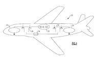
- Figure 1 shows an aircraft 20 having a main AC power bus 22.
- a first source of power 24 delivers power through a solid state power controller (SSPC) 28 to the bus 22.
- a second power source 26 delivers power through a second solid state power controller 30 to the bus 22.
- SSPC solid state power controller
- a control 19 selectively operates the SSPCs 28 and 30 to open or close to communicate the power sources 24 and 26 to the bus 22.
- the control 19 can include one or more microcontrollers, memory, input/output interfaces, and/or additional circuitry configured to achieve the referenced control functions.
- the power sources 24 and 26 may be gas turbine engines, and one may be an APU (for example 24), while the other (for example 26) may be a main gas turbine engine for the aircraft 20.
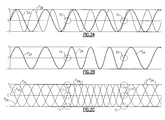
- Figure 2A shows a control method which would be utilized by the control 19 to reduce or eliminate the break.
- the SSPCs 28, 30 or control 19 can measure voltage, current and frequency from the two power sources 24 and 26.
- a power wave is identified at P24, and is provided by the power source 24, which may be the APU.
- the second wave P26 is from the power source 26 associated with the main gas turbine engine.
- the control 19 compares their characteristics, and finds switching or sync points 15. These sync points 15 are utilized as a time to switch the SSPCs 28 and 30, and in particular to open the SSPC 28 and close the SSPC 30 such that power now flows to the bus 22 from the power source 26, and no longer from the power source 24.
- the power source 24 may be delivering at a different frequency than the power source 26. As an example only, power source 24 may deliver at 400Hz, while power source 26 may deliver at 600Hz.
- each of the SSPCs 28 and 30 would typically include a digital signal processor.
- This digital signal processor can identify analog values of the voltage, and typically do so on every short period of time. As an example, every 10 microseconds the voltage is identified. By sampling these voltages, the digital signal processors can identify a wave form for the voltages.
- the control 19 can simply be an interaction between the digital signal processors in the two SSPCs, or could be a central control. In either case, the control 19 compares the two voltage wave signals from the SSPCs 28 and 30, and identifies whether they are rising and falling. A sync point is identified when each of the two signals is moving in the same direction (e.g. rising or falling) and the voltage levels will be the same. Of course, a common inflection point could also be used. It is at that point that the switch would typically occur.
- the first sync point 15 can be provided with little or no break, and a second sync point 15 is indicative of a switch back to the source 24. Occupants of the aircraft, or other system incorporating such a control, would see little apparent interruption during the switching. In fact, there may be no interruption at all.
- Figure 2C shows the sync points as they would appear across three phases of power.
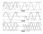
- Figure 3A shows abnormal operation, and in particular, a failure of the power source 24.
- the power source 24 has failed.
- the control 19 waits for the next zero switching or sync point 34 of the power source 26 and performs the switching at that point, which maintains the phase relationship when transitioning between power sources 24 and 26.
- the apparent overall control would have a short period of interruption of power 37 leading to the point 38 wherein the switch is made to the power source 26.
- Figure 3C shows the apparent result across three phases of power, and shows distinct switching points 48, 50 and 52 for switching from three failed waves 40, 42, and 44 to the three replacement waves 49, 51 and 53. Again, while looking for the zero switching or sync point, and waiting for that point to perform the switch, there is less apparent interruption at the switching.
- the above system is particularly useful for AC systems, and could be 115V, 230V, or other type systems.
- the SSPCs 28 and 30 provide fast, synchronized switching, and minimize any apparent interruption.
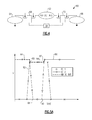
- FIG. 4 shows a DC system 60. Again, there are power sources 64 and 66 delivering power through solid state power controllers 68 and 70 to a DC bus 62. Control 19 controls SSPCs 68 and 70.
- the identification of the sync points in this DC embodiment would be simpler than in the AC embodiment. Here all that is necessary is to identify the level of voltage, and the control need not identify whether that constant voltage would be rising or falling.
- the digital signal processor typically incorporated into the SSPCs 68 and 70 can operate as mentioned above in the AC embodiment.
- Figure 5B shows a failure of one power source 80, moving downwardly to a break point 88.
- the second power source ramps rapidly upwardly at 92 from the break point 88 to a steady state at 94.
- the break point 88 need not be zero volts depending on the reaction time of the DC system 60.
Landscapes
- Engineering & Computer Science (AREA)
- Power Engineering (AREA)
- Business, Economics & Management (AREA)
- Emergency Management (AREA)
- Supply And Distribution Of Alternating Current (AREA)
- Direct Current Feeding And Distribution (AREA)
Abstract
Description
- This application relates to a power transfer between two power sources and an accessory bus, such as may be associated with an aircraft.
- Modem aircraft typically power any number of applications. Generators generate power and deliver that power to power buses that run across the length of the aircraft. In addition, power is supplied for functions such as providing air, light, etc., to the aircraft cabin. This is but a short listing of potential components powered from the bus.
- In modem aircraft, an auxiliary power unit (APU) includes a source of power, such as a small gas turbine engine, which drives a generator.
- Gas turbine engines on the aircraft also drive generators, to produce electric power to be delivered to the bus. When the aircraft is on the ground, the main gas turbine engines have yet to be started, and are not delivering significant power. Instead, at that time, power is supplied by the APU. At some point, power is transferred to the bus by opening a switch associated with the APU, and closing a switch to deliver power from the main gas turbine engine generators.
- Such a point in time is typically associated with an apparent break to the aircraft occupants. As an example, lights may flicker, air flow may stop momentarily, etc.
- A method of controlling a power system provides at least two alternative sources of power delivering power to a power bus. Switches are provided between each of the at least two sources of power and the power bus. The bus is powered by a first of the at least two sources of power. A characteristic of the power supplied by the sources of power is monitored. Switching from the first source of power to a second source of power occurs by opening a switch associated with the first source of power, and closing the switch associated with the second source of power. The timing for performing the switching is selected such that one or more characteristics of the power supplied by the first and second sources of power are close to each other to minimize the apparent break in the power supplied to the accessory bus.
- A power system incorporating controls for effecting the method as described above is also disclosed and claimed.
- These and other features of the present invention can be best understood from the following specification and drawings, the following of which is a brief description.
-
-
Figure 1 schematically shows a power architecture for an aircraft. -
Figure 2A shows a first example of a switching operation. -
Figure 2B shows the result of theFigure 2A switching. -
Figure 2C shows three phases of theFigure 2B output. -
Figure 3A shows abnormal operation. -
Figure 3B shows a switching point. -
Figure 3C shows the switching ofFigure 3B across three phases. -
Figure 4 shows a second embodiment. -
Figure 5A shows normal switching operation. -
Figure 5B shows abnormal operation. -
Figure 1 shows anaircraft 20 having a mainAC power bus 22. A first source ofpower 24 delivers power through a solid state power controller (SSPC) 28 to thebus 22. Asecond power source 26 delivers power through a second solidstate power controller 30 to thebus 22. - A
control 19 selectively operates theSSPCs power sources bus 22. Thecontrol 19 can include one or more microcontrollers, memory, input/output interfaces, and/or additional circuitry configured to achieve the referenced control functions. Thepower sources aircraft 20. - As mentioned above, as the
aircraft 20 switches from APU power to the main gas turbine engine power, there is a noticeable break in continuity of delivered power. -
Figure 2A shows a control method which would be utilized by thecontrol 19 to reduce or eliminate the break. - The
SSPCs control 19 can measure voltage, current and frequency from the twopower sources - Thus, as shown in
Figure 2A , a power wave is identified at P24, and is provided by thepower source 24, which may be the APU. The second wave P26 is from thepower source 26 associated with the main gas turbine engine. - When it is desired to switch from power being powered by the
power source 24 to thepower source 26, thecontrol 19 compares their characteristics, and finds switching orsync points 15. Thesesync points 15 are utilized as a time to switch theSSPCs bus 22 from thepower source 26, and no longer from thepower source 24. Thepower source 24 may be delivering at a different frequency than thepower source 26. As an example only,power source 24 may deliver at 400Hz, whilepower source 26 may deliver at 600Hz. - The sync points can be identified in any number of ways. As one way, each of the SSPCs 28 and 30 would typically include a digital signal processor. This digital signal processor can identify analog values of the voltage, and typically do so on every short period of time. As an example, every 10 microseconds the voltage is identified. By sampling these voltages, the digital signal processors can identify a wave form for the voltages.
- The
control 19 can simply be an interaction between the digital signal processors in the two SSPCs, or could be a central control. In either case, thecontrol 19 compares the two voltage wave signals from theSSPCs - As can be appreciated in
Figure 2B , thefirst sync point 15 can be provided with little or no break, and asecond sync point 15 is indicative of a switch back to thesource 24. Occupants of the aircraft, or other system incorporating such a control, would see little apparent interruption during the switching. In fact, there may be no interruption at all. -
Figure 2C shows the sync points as they would appear across three phases of power. -
Figure 3A shows abnormal operation, and in particular, a failure of thepower source 24. Thus, as shown atpoint 32, thepower source 24 has failed. Thecontrol 19 waits for the next zero switching orsync point 34 of thepower source 26 and performs the switching at that point, which maintains the phase relationship when transitioning betweenpower sources Figure 3B , the apparent overall control would have a short period of interruption ofpower 37 leading to thepoint 38 wherein the switch is made to thepower source 26. -
Figure 3C shows the apparent result across three phases of power, and shows distinct switching points 48, 50 and 52 for switching from three failedwaves replacement waves 49, 51 and 53. Again, while looking for the zero switching or sync point, and waiting for that point to perform the switch, there is less apparent interruption at the switching. - It should be understood that the abnormal operation, or failure, could occur to either of the two
power sources - The above system is particularly useful for AC systems, and could be 115V, 230V, or other type systems. The SSPCs 28 and 30 provide fast, synchronized switching, and minimize any apparent interruption.
-
Figure 4 shows aDC system 60. Again, there arepower sources state power controllers DC bus 62.Control 19 controls SSPCs 68 and 70. - As shown in
Figure 5A , during normal operation, the voltage of onepower source 80 drops toward zero atpoint 88, and resumes at point 90 back up to 86. During the interim, theother power source 82 moves rapidly upwardly to 84. Thecontrol 19 looks for switching or sync points 85 and 87, and utilizes these switching points to switch between the twopower sources Figure 5A , it can of course be spaced by much greater lengths of time. - The identification of the sync points in this DC embodiment would be simpler than in the AC embodiment. Here all that is necessary is to identify the level of voltage, and the control need not identify whether that constant voltage would be rising or falling. Again, the digital signal processor typically incorporated into the
SSPCs -
Figure 5B shows a failure of onepower source 80, moving downwardly to abreak point 88. The second power source ramps rapidly upwardly at 92 from thebreak point 88 to a steady state at 94. Thebreak point 88 need not be zero volts depending on the reaction time of theDC system 60. - There may be any number of reasons for switching between the two
DC power sources DC system 60. It is the control method of looking for a switching or sync point, and waiting for that point to occur to perform the switching that provides minimizes the apparent interruption. - While the switching is shown at the exact synchronization point in this application and drawings, it should be understood that all that is required is for the switching to occur at a point that approaches close synchronization for the apparent interruption to be minimized.
- Although an embodiment of this invention has been disclosed, a worker of ordinary skill in this art would recognize that certain modifications would come within the scope of this invention. For that reason, the following claims should be studied to determine the true scope and content of this invention.
Claims (15)
- A method of controlling a power system comprising the steps of:(a) providing at least two alternative sources of power (24,26;64,66) for delivering power to a power bus (22;62);(b) providing switches (28,30;68,70) between each of said at least two sources of power and said power bus;(c) powering said power bus with a first of said at least two sources of power, and monitoring a characteristic of the power supplied by said at least two sources of power, and switching from said first source of power (24;64) to a second (26;66) of said at least two sources of power by opening a switch (28;68) associated with said first source of power, and closing a switch (30;70) associated with said second source of power, and the switching being performed at a point (15;34;48,50,52;85,87;88) such that one or more characteristics of the power supplied by said first and second sources of power are close to each other to minimize an apparent break in the power supplied to the power bus (22;62).
- The method as set forth in claim 1, wherein the point of switching (15;34;48, 50,52;85,87,88) is selected such that the two sources of power are synchronized.
- The method as set forth in claim 1 or 2, wherein the power system is an AC power system, and the monitored characteristic includes one or more of voltage and current, preferably wherein said first (24) and second (26) power sources provide distinct frequencies of power.
- The method as set forth in claim 1, 2 or 3, wherein the switching is performed as a normal operation to switch between two sources of power, and sync points (15;34;48,50,52;85,87;88) of the power provided by said first and second sources of power are selected as the point at which to switch.
- The method as set forth in any preceding claim, wherein said at least two sources of power (24,26) include an auxiliary power unit and a main gas turbine engine on an aircraft.
- The method as set forth in claim 1 or 2, wherein the power system is a DC power system (60), and the monitored characteristic includes voltage.
- The method as set forth in any preceding claim, wherein the point of switching occurs with a fault of at least one of said first and second sources of power, and the switching occurs at a zero switching or sync point (15;34;48,50,52; 85,87,88) of the second source of power.
- The method as set forth in any preceding claim, wherein the first source of power (24;64) delivers a higher voltage than the second source of power (26;66), and the switching occurs as said first source of power drops across the voltage level provided by said second source of power.
- The method as set forth in claim 1, 2 or 6, wherein said first source of power (64) is a faulted DC power source, and said switching point to said second source of power (66) is initiated at zero voltage as said first source of power approximates a voltage supply of zero.
- A power system comprising:at least two alternative sources of power (24,26;64,66) for delivering power to a power bus (22;62);switches (28,30;68,70) between each of said at least two sources of power and said power bus;a control (19) powering said power bus (22;62) with a first of said at least two sources of power, and monitoring a characteristic of the power supplied by said at least two sources of power, and switching from said first source of power (24;64) to a second (26;66) of said at least two sources of power by opening a switch (28;68) associated with said first source of power, and closing a switch (30;70) associated with said second source of power, and the switching being performed at a point such that one or more characteristics of the power supplied by said first and second sources of power are close to each other to minimize an apparent break in the power supplied to the power bus.
- The system as set forth in claim 10, wherein the control (19) selects a point of switching when the first and second sources of power (24,26;64,66) are synchronized.
- The system as set forth in claim 10 or 11, wherein the power system is an AC power system, and the monitored characteristic includes one or more of voltage and current.
- The system as set forth in claim 10, 11 or 12, wherein the switching is performed as a normal operation to switch between two sources of power, and sync points (15;34;48,50,52;85,87;88) of the power provided by said first and second sources of power are selected as the switching point.
- The system as set forth in claim 10, 11, 12 or 13, wherein said at least two sources of power include an auxiliary power unit (APU) and a main gas turbine engine on an aircraft, preferably wherein said APU and said main gas turbine engine power generators provide two distinct frequencies of power.
- The system as set forth in claim 10, wherein the power system is a DC power system (60), and the monitored characteristic includes voltage.
Applications Claiming Priority (1)
| Application Number | Priority Date | Filing Date | Title |
|---|---|---|---|
| US12/834,183 US8446041B2 (en) | 2010-07-12 | 2010-07-12 | No break power transfer with solid state power controls |
Publications (3)
| Publication Number | Publication Date |
|---|---|
| EP2408084A2 true EP2408084A2 (en) | 2012-01-18 |
| EP2408084A3 EP2408084A3 (en) | 2014-08-13 |
| EP2408084B1 EP2408084B1 (en) | 2021-05-26 |
Family
ID=44801250
Family Applications (1)
| Application Number | Title | Priority Date | Filing Date |
|---|---|---|---|
| EP11173569.2A Active EP2408084B1 (en) | 2010-07-12 | 2011-07-12 | No break power transfer with solid state power controls |
Country Status (2)
| Country | Link |
|---|---|
| US (1) | US8446041B2 (en) |
| EP (1) | EP2408084B1 (en) |
Cited By (1)
| Publication number | Priority date | Publication date | Assignee | Title |
|---|---|---|---|---|
| EP3101750A1 (en) * | 2015-05-13 | 2016-12-07 | Hamilton Sundstrand Corporation | High power solid state switches for aircraft |
Families Citing this family (1)
| Publication number | Priority date | Publication date | Assignee | Title |
|---|---|---|---|---|
| US9660446B2 (en) * | 2013-10-04 | 2017-05-23 | Ge Aviation Systems Llc | Power distribution system for an aircraft |
Family Cites Families (20)
| Publication number | Priority date | Publication date | Assignee | Title |
|---|---|---|---|---|
| US5210685A (en) * | 1985-03-08 | 1993-05-11 | Westinghouse Electric Corp. | Uninterruptible power supply system and load transfer static switch for such a system |
| CA1267717A (en) | 1987-07-29 | 1990-04-10 | Alfred M. Hase | High speed load transfer system |
| US4761563A (en) * | 1987-10-27 | 1988-08-02 | International Business Machines Corporation | Asynchronous multiphase switching gear |
| US4874961A (en) | 1988-10-31 | 1989-10-17 | Sundstrand Corporation | Electrical power generating system having parallel generator control |
| US4937462A (en) | 1989-01-23 | 1990-06-26 | Sundstrand Corporation | No break power transfer control for a VSCF power generating system |
| US5182464A (en) * | 1991-01-09 | 1993-01-26 | Techmatics, Inc. | High speed transfer switch |
| US5317500A (en) | 1992-08-06 | 1994-05-31 | Sundstrand Corporation | Active no-break power transfer control for a VSCF power generating system |
| US5729059A (en) | 1995-06-07 | 1998-03-17 | Kilroy; Donald G. | Digital no-break power transfer system |
| GB0031057D0 (en) * | 2000-12-20 | 2001-01-31 | Lucas Industries Ltd | Power transfer system |
| US6992403B1 (en) * | 2001-03-08 | 2006-01-31 | Pacific Scientific | Electric power and start system |
| US6657416B2 (en) * | 2001-06-15 | 2003-12-02 | Generac Power Systems, Inc. | Control system for stand-by electrical generator |
| US6630752B2 (en) * | 2001-09-12 | 2003-10-07 | Qualmag, Inc. | Uninterruptible transfer switch |
| US7157811B2 (en) * | 2003-02-28 | 2007-01-02 | Kohler Co. | Method and apparatus for sensing voltage in an automatic transfer switch system |
| US6806589B1 (en) | 2003-07-21 | 2004-10-19 | Hamilton Sundstrand Corporation | No break electric power transfer system |
| US7417337B1 (en) | 2003-09-04 | 2008-08-26 | Hamilton Sundstrand Corporation | Method and system for facilitating no-break power transfer |
| US7254465B2 (en) * | 2004-06-04 | 2007-08-07 | Honeywell International, Inc. | No-break-power-transfer control system for variable frequency electrical power systems |
| FR2900635B1 (en) * | 2006-05-05 | 2008-07-25 | Hispano Suiza Sa | SYSTEM FOR SUPPLYING AND CONTROLLING ELECTRICAL EQUIPMENT OF AN AIRCRAFT ENGINE OR ITS ENVIRONMENT |
| EP1890371A1 (en) * | 2006-08-03 | 2008-02-20 | Michael J. Mosman | UPS system configuration comprising parallel modules being independent of each other |
| US7677135B2 (en) | 2007-07-18 | 2010-03-16 | Hamilton Sundstrand Corporation | Electromechanical power transfer system with multiple dynamoelectric machines |
| US8159086B2 (en) * | 2009-04-30 | 2012-04-17 | Ge Aviation Systems Llc | Methods and systems for no-break power transfer converter |
-
2010
- 2010-07-12 US US12/834,183 patent/US8446041B2/en active Active
-
2011
- 2011-07-12 EP EP11173569.2A patent/EP2408084B1/en active Active
Non-Patent Citations (1)
| Title |
|---|
| None |
Cited By (1)
| Publication number | Priority date | Publication date | Assignee | Title |
|---|---|---|---|---|
| EP3101750A1 (en) * | 2015-05-13 | 2016-12-07 | Hamilton Sundstrand Corporation | High power solid state switches for aircraft |
Also Published As
| Publication number | Publication date |
|---|---|
| EP2408084B1 (en) | 2021-05-26 |
| EP2408084A3 (en) | 2014-08-13 |
| US8446041B2 (en) | 2013-05-21 |
| US20120007427A1 (en) | 2012-01-12 |
Similar Documents
| Publication | Publication Date | Title |
|---|---|---|
| RU2416871C2 (en) | Power and control system of electric equipment of aircraft engine, and its instrumentation | |
| JP6110648B2 (en) | System and method for power distribution | |
| US7936082B2 (en) | Electrical power supply circuit in an aircraft for electrical equipment including a de-icing circuit | |
| US8946928B2 (en) | Power distribution system and method thereof | |
| EP2028104B1 (en) | Generator for gas turbine engine having DC bus fault short circuit control using a battery | |
| RU2646012C2 (en) | Method of controlling network of electric power supply of air vehicle | |
| US20070257558A1 (en) | Electrical power supply arrangement for an aircraft | |
| EP2028758B1 (en) | Engine having power bus fault short circuit control with a disconnection switch | |
| RU2400900C2 (en) | Electric supply of aircraft gas turbine engine equipment | |
| CA2759384C (en) | Methods and systems for no-break power transfer with a converter | |
| US20080211237A1 (en) | Electrical power supply for an aircraft | |
| US9035478B2 (en) | Aircraft engine constant frequency starter/generator | |
| CN102336275A (en) | Method for aircraft emergency power management | |
| WO2016178054A1 (en) | System and method for electric power distribution and load leveling on aircrafts | |
| JP2001502518A (en) | System and method for continuously supplying power to a mounted electric device | |
| EP2648322A1 (en) | Power interruption bridge circuit | |
| US5550455A (en) | Standby generator pulse excitation system and electric power generating system for use therein | |
| WO2024023305A1 (en) | An energy distribution system | |
| US10266129B2 (en) | Vehicle control system | |
| KR101422905B1 (en) | Meduim voltage inverter control apparatus and meduim voltage inverter system | |
| US8446041B2 (en) | No break power transfer with solid state power controls | |
| US9114888B2 (en) | RAM air turbine smoke isolation | |
| US11384694B2 (en) | Auxiliary device system of aircraft engine | |
| CN117597847A (en) | Electrical architecture for aircraft | |
| RU107008U1 (en) | AUTONOMOUS STARTER-GENERATOR POWER SUPPLY SYSTEM |
Legal Events
| Date | Code | Title | Description |
|---|---|---|---|
| AK | Designated contracting states |
Kind code of ref document: A2 Designated state(s): AL AT BE BG CH CY CZ DE DK EE ES FI FR GB GR HR HU IE IS IT LI LT LU LV MC MK MT NL NO PL PT RO RS SE SI SK SM TR |
|
| AX | Request for extension of the european patent |
Extension state: BA ME |
|
| PUAI | Public reference made under article 153(3) epc to a published international application that has entered the european phase |
Free format text: ORIGINAL CODE: 0009012 |
|
| PUAL | Search report despatched |
Free format text: ORIGINAL CODE: 0009013 |
|
| AK | Designated contracting states |
Kind code of ref document: A3 Designated state(s): AL AT BE BG CH CY CZ DE DK EE ES FI FR GB GR HR HU IE IS IT LI LT LU LV MC MK MT NL NO PL PT RO RS SE SI SK SM TR |
|
| AX | Request for extension of the european patent |
Extension state: BA ME |
|
| RIC1 | Information provided on ipc code assigned before grant |
Ipc: H02J 3/00 20060101ALI20140704BHEP Ipc: H02J 9/06 20060101ALI20140704BHEP Ipc: H02J 4/00 20060101AFI20140704BHEP |
|
| 17P | Request for examination filed |
Effective date: 20141229 |
|
| RBV | Designated contracting states (corrected) |
Designated state(s): AL AT BE BG CH CY CZ DE DK EE ES FI FR GB GR HR HU IE IS IT LI LT LU LV MC MK MT NL NO PL PT RO RS SE SI SK SM TR |
|
| GRAP | Despatch of communication of intention to grant a patent |
Free format text: ORIGINAL CODE: EPIDOSNIGR1 |
|
| STAA | Information on the status of an ep patent application or granted ep patent |
Free format text: STATUS: GRANT OF PATENT IS INTENDED |
|
| INTG | Intention to grant announced |
Effective date: 20201215 |
|
| GRAS | Grant fee paid |
Free format text: ORIGINAL CODE: EPIDOSNIGR3 |
|
| GRAA | (expected) grant |
Free format text: ORIGINAL CODE: 0009210 |
|
| STAA | Information on the status of an ep patent application or granted ep patent |
Free format text: STATUS: THE PATENT HAS BEEN GRANTED |
|
| RAP3 | Party data changed (applicant data changed or rights of an application transferred) |
Owner name: HAMILTON SUNDSTRAND CORPORATION |
|
| AK | Designated contracting states |
Kind code of ref document: B1 Designated state(s): AL AT BE BG CH CY CZ DE DK EE ES FI FR GB GR HR HU IE IS IT LI LT LU LV MC MK MT NL NO PL PT RO RS SE SI SK SM TR |
|
| REG | Reference to a national code |
Ref country code: GB Ref legal event code: FG4D |
|
| REG | Reference to a national code |
Ref country code: CH Ref legal event code: EP |
|
| REG | Reference to a national code |
Ref country code: AT Ref legal event code: REF Ref document number: 1397203 Country of ref document: AT Kind code of ref document: T Effective date: 20210615 |
|
| REG | Reference to a national code |
Ref country code: DE Ref legal event code: R096 Ref document number: 602011071009 Country of ref document: DE |
|
| REG | Reference to a national code |
Ref country code: IE Ref legal event code: FG4D |
|
| REG | Reference to a national code |
Ref country code: LT Ref legal event code: MG9D |
|
| REG | Reference to a national code |
Ref country code: AT Ref legal event code: MK05 Ref document number: 1397203 Country of ref document: AT Kind code of ref document: T Effective date: 20210526 |
|
| PG25 | Lapsed in a contracting state [announced via postgrant information from national office to epo] |
Ref country code: AT Free format text: LAPSE BECAUSE OF FAILURE TO SUBMIT A TRANSLATION OF THE DESCRIPTION OR TO PAY THE FEE WITHIN THE PRESCRIBED TIME-LIMIT Effective date: 20210526 Ref country code: BG Free format text: LAPSE BECAUSE OF FAILURE TO SUBMIT A TRANSLATION OF THE DESCRIPTION OR TO PAY THE FEE WITHIN THE PRESCRIBED TIME-LIMIT Effective date: 20210826 Ref country code: HR Free format text: LAPSE BECAUSE OF FAILURE TO SUBMIT A TRANSLATION OF THE DESCRIPTION OR TO PAY THE FEE WITHIN THE PRESCRIBED TIME-LIMIT Effective date: 20210526 Ref country code: FI Free format text: LAPSE BECAUSE OF FAILURE TO SUBMIT A TRANSLATION OF THE DESCRIPTION OR TO PAY THE FEE WITHIN THE PRESCRIBED TIME-LIMIT Effective date: 20210526 Ref country code: LT Free format text: LAPSE BECAUSE OF FAILURE TO SUBMIT A TRANSLATION OF THE DESCRIPTION OR TO PAY THE FEE WITHIN THE PRESCRIBED TIME-LIMIT Effective date: 20210526 |
|
| REG | Reference to a national code |
Ref country code: NL Ref legal event code: MP Effective date: 20210526 |
|
| PG25 | Lapsed in a contracting state [announced via postgrant information from national office to epo] |
Ref country code: RS Free format text: LAPSE BECAUSE OF FAILURE TO SUBMIT A TRANSLATION OF THE DESCRIPTION OR TO PAY THE FEE WITHIN THE PRESCRIBED TIME-LIMIT Effective date: 20210526 Ref country code: SE Free format text: LAPSE BECAUSE OF FAILURE TO SUBMIT A TRANSLATION OF THE DESCRIPTION OR TO PAY THE FEE WITHIN THE PRESCRIBED TIME-LIMIT Effective date: 20210526 Ref country code: IS Free format text: LAPSE BECAUSE OF FAILURE TO SUBMIT A TRANSLATION OF THE DESCRIPTION OR TO PAY THE FEE WITHIN THE PRESCRIBED TIME-LIMIT Effective date: 20210926 Ref country code: GR Free format text: LAPSE BECAUSE OF FAILURE TO SUBMIT A TRANSLATION OF THE DESCRIPTION OR TO PAY THE FEE WITHIN THE PRESCRIBED TIME-LIMIT Effective date: 20210827 Ref country code: LV Free format text: LAPSE BECAUSE OF FAILURE TO SUBMIT A TRANSLATION OF THE DESCRIPTION OR TO PAY THE FEE WITHIN THE PRESCRIBED TIME-LIMIT Effective date: 20210526 Ref country code: PT Free format text: LAPSE BECAUSE OF FAILURE TO SUBMIT A TRANSLATION OF THE DESCRIPTION OR TO PAY THE FEE WITHIN THE PRESCRIBED TIME-LIMIT Effective date: 20210927 Ref country code: NO Free format text: LAPSE BECAUSE OF FAILURE TO SUBMIT A TRANSLATION OF THE DESCRIPTION OR TO PAY THE FEE WITHIN THE PRESCRIBED TIME-LIMIT Effective date: 20210826 Ref country code: PL Free format text: LAPSE BECAUSE OF FAILURE TO SUBMIT A TRANSLATION OF THE DESCRIPTION OR TO PAY THE FEE WITHIN THE PRESCRIBED TIME-LIMIT Effective date: 20210526 |
|
| PG25 | Lapsed in a contracting state [announced via postgrant information from national office to epo] |
Ref country code: NL Free format text: LAPSE BECAUSE OF FAILURE TO SUBMIT A TRANSLATION OF THE DESCRIPTION OR TO PAY THE FEE WITHIN THE PRESCRIBED TIME-LIMIT Effective date: 20210526 |
|
| PG25 | Lapsed in a contracting state [announced via postgrant information from national office to epo] |
Ref country code: RO Free format text: LAPSE BECAUSE OF FAILURE TO SUBMIT A TRANSLATION OF THE DESCRIPTION OR TO PAY THE FEE WITHIN THE PRESCRIBED TIME-LIMIT Effective date: 20210526 Ref country code: ES Free format text: LAPSE BECAUSE OF FAILURE TO SUBMIT A TRANSLATION OF THE DESCRIPTION OR TO PAY THE FEE WITHIN THE PRESCRIBED TIME-LIMIT Effective date: 20210526 Ref country code: SM Free format text: LAPSE BECAUSE OF FAILURE TO SUBMIT A TRANSLATION OF THE DESCRIPTION OR TO PAY THE FEE WITHIN THE PRESCRIBED TIME-LIMIT Effective date: 20210526 Ref country code: SK Free format text: LAPSE BECAUSE OF FAILURE TO SUBMIT A TRANSLATION OF THE DESCRIPTION OR TO PAY THE FEE WITHIN THE PRESCRIBED TIME-LIMIT Effective date: 20210526 Ref country code: DK Free format text: LAPSE BECAUSE OF FAILURE TO SUBMIT A TRANSLATION OF THE DESCRIPTION OR TO PAY THE FEE WITHIN THE PRESCRIBED TIME-LIMIT Effective date: 20210526 Ref country code: CZ Free format text: LAPSE BECAUSE OF FAILURE TO SUBMIT A TRANSLATION OF THE DESCRIPTION OR TO PAY THE FEE WITHIN THE PRESCRIBED TIME-LIMIT Effective date: 20210526 Ref country code: EE Free format text: LAPSE BECAUSE OF FAILURE TO SUBMIT A TRANSLATION OF THE DESCRIPTION OR TO PAY THE FEE WITHIN THE PRESCRIBED TIME-LIMIT Effective date: 20210526 |
|
| REG | Reference to a national code |
Ref country code: CH Ref legal event code: PL |
|
| REG | Reference to a national code |
Ref country code: DE Ref legal event code: R097 Ref document number: 602011071009 Country of ref document: DE |
|
| PLBE | No opposition filed within time limit |
Free format text: ORIGINAL CODE: 0009261 |
|
| STAA | Information on the status of an ep patent application or granted ep patent |
Free format text: STATUS: NO OPPOSITION FILED WITHIN TIME LIMIT |
|
| PG25 | Lapsed in a contracting state [announced via postgrant information from national office to epo] |
Ref country code: MC Free format text: LAPSE BECAUSE OF FAILURE TO SUBMIT A TRANSLATION OF THE DESCRIPTION OR TO PAY THE FEE WITHIN THE PRESCRIBED TIME-LIMIT Effective date: 20210526 |
|
| REG | Reference to a national code |
Ref country code: BE Ref legal event code: MM Effective date: 20210731 |
|
| PG25 | Lapsed in a contracting state [announced via postgrant information from national office to epo] |
Ref country code: LI Free format text: LAPSE BECAUSE OF NON-PAYMENT OF DUE FEES Effective date: 20210731 Ref country code: CH Free format text: LAPSE BECAUSE OF NON-PAYMENT OF DUE FEES Effective date: 20210731 |
|
| 26N | No opposition filed |
Effective date: 20220301 |
|
| PG25 | Lapsed in a contracting state [announced via postgrant information from national office to epo] |
Ref country code: IS Free format text: LAPSE BECAUSE OF FAILURE TO SUBMIT A TRANSLATION OF THE DESCRIPTION OR TO PAY THE FEE WITHIN THE PRESCRIBED TIME-LIMIT Effective date: 20210926 Ref country code: LU Free format text: LAPSE BECAUSE OF NON-PAYMENT OF DUE FEES Effective date: 20210712 Ref country code: AL Free format text: LAPSE BECAUSE OF FAILURE TO SUBMIT A TRANSLATION OF THE DESCRIPTION OR TO PAY THE FEE WITHIN THE PRESCRIBED TIME-LIMIT Effective date: 20210526 |
|
| PG25 | Lapsed in a contracting state [announced via postgrant information from national office to epo] |
Ref country code: IT Free format text: LAPSE BECAUSE OF FAILURE TO SUBMIT A TRANSLATION OF THE DESCRIPTION OR TO PAY THE FEE WITHIN THE PRESCRIBED TIME-LIMIT Effective date: 20210526 Ref country code: IE Free format text: LAPSE BECAUSE OF NON-PAYMENT OF DUE FEES Effective date: 20210712 Ref country code: BE Free format text: LAPSE BECAUSE OF NON-PAYMENT OF DUE FEES Effective date: 20210731 |
|
| PG25 | Lapsed in a contracting state [announced via postgrant information from national office to epo] |
Ref country code: HU Free format text: LAPSE BECAUSE OF FAILURE TO SUBMIT A TRANSLATION OF THE DESCRIPTION OR TO PAY THE FEE WITHIN THE PRESCRIBED TIME-LIMIT; INVALID AB INITIO Effective date: 20110712 Ref country code: CY Free format text: LAPSE BECAUSE OF FAILURE TO SUBMIT A TRANSLATION OF THE DESCRIPTION OR TO PAY THE FEE WITHIN THE PRESCRIBED TIME-LIMIT Effective date: 20210526 |
|
| P01 | Opt-out of the competence of the unified patent court (upc) registered |
Effective date: 20230522 |
|
| PG25 | Lapsed in a contracting state [announced via postgrant information from national office to epo] |
Ref country code: MK Free format text: LAPSE BECAUSE OF FAILURE TO SUBMIT A TRANSLATION OF THE DESCRIPTION OR TO PAY THE FEE WITHIN THE PRESCRIBED TIME-LIMIT Effective date: 20210526 |
|
| PG25 | Lapsed in a contracting state [announced via postgrant information from national office to epo] |
Ref country code: TR Free format text: LAPSE BECAUSE OF FAILURE TO SUBMIT A TRANSLATION OF THE DESCRIPTION OR TO PAY THE FEE WITHIN THE PRESCRIBED TIME-LIMIT Effective date: 20210526 |
|
| PG25 | Lapsed in a contracting state [announced via postgrant information from national office to epo] |
Ref country code: MT Free format text: LAPSE BECAUSE OF FAILURE TO SUBMIT A TRANSLATION OF THE DESCRIPTION OR TO PAY THE FEE WITHIN THE PRESCRIBED TIME-LIMIT Effective date: 20210526 |
|
| PGFP | Annual fee paid to national office [announced via postgrant information from national office to epo] |
Ref country code: GB Payment date: 20250619 Year of fee payment: 15 |
|
| PGFP | Annual fee paid to national office [announced via postgrant information from national office to epo] |
Ref country code: FR Payment date: 20250620 Year of fee payment: 15 |
|
| PGFP | Annual fee paid to national office [announced via postgrant information from national office to epo] |
Ref country code: DE Payment date: 20250620 Year of fee payment: 15 |