EP2408042A1 - Battery pack - Google Patents
Battery pack Download PDFInfo
- Publication number
- EP2408042A1 EP2408042A1 EP11173465A EP11173465A EP2408042A1 EP 2408042 A1 EP2408042 A1 EP 2408042A1 EP 11173465 A EP11173465 A EP 11173465A EP 11173465 A EP11173465 A EP 11173465A EP 2408042 A1 EP2408042 A1 EP 2408042A1
- Authority
- EP
- European Patent Office
- Prior art keywords
- frame
- battery pack
- sub
- secondary battery
- pack according
- Prior art date
- Legal status (The legal status is an assumption and is not a legal conclusion. Google has not performed a legal analysis and makes no representation as to the accuracy of the status listed.)
- Granted
Links
Images




Classifications
-
- H—ELECTRICITY
- H01—ELECTRIC ELEMENTS
- H01M—PROCESSES OR MEANS, e.g. BATTERIES, FOR THE DIRECT CONVERSION OF CHEMICAL ENERGY INTO ELECTRICAL ENERGY
- H01M50/00—Constructional details or processes of manufacture of the non-active parts of electrochemical cells other than fuel cells, e.g. hybrid cells
- H01M50/50—Current conducting connections for cells or batteries
- H01M50/543—Terminals
-
- H—ELECTRICITY
- H01—ELECTRIC ELEMENTS
- H01M—PROCESSES OR MEANS, e.g. BATTERIES, FOR THE DIRECT CONVERSION OF CHEMICAL ENERGY INTO ELECTRICAL ENERGY
- H01M10/00—Secondary cells; Manufacture thereof
- H01M10/42—Methods or arrangements for servicing or maintenance of secondary cells or secondary half-cells
- H01M10/4207—Methods or arrangements for servicing or maintenance of secondary cells or secondary half-cells for several batteries or cells simultaneously or sequentially
-
- H—ELECTRICITY
- H01—ELECTRIC ELEMENTS
- H01M—PROCESSES OR MEANS, e.g. BATTERIES, FOR THE DIRECT CONVERSION OF CHEMICAL ENERGY INTO ELECTRICAL ENERGY
- H01M50/00—Constructional details or processes of manufacture of the non-active parts of electrochemical cells other than fuel cells, e.g. hybrid cells
- H01M50/20—Mountings; Secondary casings or frames; Racks, modules or packs; Suspension devices; Shock absorbers; Transport or carrying devices; Holders
- H01M50/204—Racks, modules or packs for multiple batteries or multiple cells
- H01M50/207—Racks, modules or packs for multiple batteries or multiple cells characterised by their shape
- H01M50/209—Racks, modules or packs for multiple batteries or multiple cells characterised by their shape adapted for prismatic or rectangular cells
-
- H—ELECTRICITY
- H01—ELECTRIC ELEMENTS
- H01M—PROCESSES OR MEANS, e.g. BATTERIES, FOR THE DIRECT CONVERSION OF CHEMICAL ENERGY INTO ELECTRICAL ENERGY
- H01M50/00—Constructional details or processes of manufacture of the non-active parts of electrochemical cells other than fuel cells, e.g. hybrid cells
- H01M50/50—Current conducting connections for cells or batteries
- H01M50/528—Fixed electrical connections, i.e. not intended for disconnection
-
- H—ELECTRICITY
- H01—ELECTRIC ELEMENTS
- H01M—PROCESSES OR MEANS, e.g. BATTERIES, FOR THE DIRECT CONVERSION OF CHEMICAL ENERGY INTO ELECTRICAL ENERGY
- H01M50/00—Constructional details or processes of manufacture of the non-active parts of electrochemical cells other than fuel cells, e.g. hybrid cells
- H01M50/50—Current conducting connections for cells or batteries
- H01M50/572—Means for preventing undesired use or discharge
-
- H—ELECTRICITY
- H01—ELECTRIC ELEMENTS
- H01M—PROCESSES OR MEANS, e.g. BATTERIES, FOR THE DIRECT CONVERSION OF CHEMICAL ENERGY INTO ELECTRICAL ENERGY
- H01M50/00—Constructional details or processes of manufacture of the non-active parts of electrochemical cells other than fuel cells, e.g. hybrid cells
- H01M50/50—Current conducting connections for cells or batteries
- H01M50/572—Means for preventing undesired use or discharge
- H01M50/574—Devices or arrangements for the interruption of current
- H01M50/581—Devices or arrangements for the interruption of current in response to temperature
-
- Y—GENERAL TAGGING OF NEW TECHNOLOGICAL DEVELOPMENTS; GENERAL TAGGING OF CROSS-SECTIONAL TECHNOLOGIES SPANNING OVER SEVERAL SECTIONS OF THE IPC; TECHNICAL SUBJECTS COVERED BY FORMER USPC CROSS-REFERENCE ART COLLECTIONS [XRACs] AND DIGESTS
- Y02—TECHNOLOGIES OR APPLICATIONS FOR MITIGATION OR ADAPTATION AGAINST CLIMATE CHANGE
- Y02E—REDUCTION OF GREENHOUSE GAS [GHG] EMISSIONS, RELATED TO ENERGY GENERATION, TRANSMISSION OR DISTRIBUTION
- Y02E60/00—Enabling technologies; Technologies with a potential or indirect contribution to GHG emissions mitigation
- Y02E60/10—Energy storage using batteries
Definitions
- the invention relates to a battery pack, particularly a battery pack including a plurality of secondary batteries.
- the secondary batteries themselves or include a plurality of secondary batteries in one pack, in order to increase capacity.
- Increasing the size of the secondary batteries can cause a problem in terms of safety. Therefore, efforts have concentrated on providing a plurality of secondary batteries in one battery pack and improving performance of the battery pack.
- the present invention sets out to provide a battery pack that may be manufactured to have high capacity by including a plurality of secondary batteries in the battery pack.
- the present invention sets out to provide a battery pack in which the number of componets is minimised.
- the invention provides a battery pack as set out in claim 1.
- Preferred features of the invention are set out in claims 2 to 15.
- embodiments of the invention can make it possible to reduce the number of parts compared to a conventional battery pack, production costs can be reduced. Since aproduction method for the battery pack can then also be made simple, manufacturing efficiency can be improved.
- a battery pack it is possible to connect a plurality of secondary battery cells, using a single PCM assembly.
- This can be particularly effective in in simplifying the structure of the battery pack and furthermore the PCM assembly can serve to secure the position of the secondary battery cells accommodated in the battery pack so that they are not moved in the battery pack by an external shock, such as drop, and they are thus electrically stable.
- some embodiments of a battery pack according to the present invention provide a case fixing a plurality of secondary battery cells, which enhances stability of the structure.
- the case may be easily modified in accordance with the shape of the secondary batteries accommodated in the battery pack.
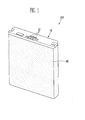
- FIG. 1 is a perspective view of a battery pack according to an embodiment of the present invention
- FIG. 2 is an exploded view of the battery pack shown in FIG. 1 ;
- FIG. 3 is an exploded view of the secondary battery accommodated in the battery pack shown in FIG. 1 ;
- FIG. 4A is a perspective view of a sub-frame included in the battery pack shown in FIG. 1 ;
- FIG. 4B is a perspective view of the sub-frame rotated at 180° from FIG. 4A ;
- FIG. 5 is a perspective view illustrating that the secondary battery is accommodated in the sub-frame and schematically showing a PCM assembly
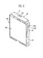
- FIG. 6 is a perspective view of the sub-frame equipped with the secondary battery and the PCM assembly
- FIG. 7 is a perspective view of the sub-frame equipped with first and second main frame
- FIG. 8 is a cross-sectional view taken along line A-A of FIG. 7 ;
- FIG. 9 is a perspective view showing a battery pack according to another embodiment of the present invention.
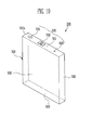
- FIG. 10 is a perspective view of the secondary battery accommodated in the battery pack shown in FIG. 9 ;
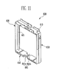
- FIG. 11 is a perspective view of a sub-frame included in the battery pack shown in FIG. 9 .
- FIG. 1 is a perspective view of a battery pack according to an embodiment of the present invention and FIG. 2 is an exploded view of the battery pack according to this embodiment.
- FIG. 3 is an exploded view of a secondary battery cell according to this embodiment.
- a battery pack 100 includes: a plurality of secondary battery cells 200 and a rectangular sub-frame 300 fixing the sides of the secondary battery cells 200 and having an opening corresponding to the bottoms of the secondary battery cells 200. Further, the battery pack 100 further includes: a PCM assembly 30 attached to a side of the sub-frame 300 and electrically connected with the secondary battery cells 200; first and second main frames 10, 20 covering the sides of the sub-frame 300; and a covering member 40 covering the first and second main frame 10, 20 and the secondary battery cells 200.
- this embodiment includes the sub-frame 300 and main frames 10, 20, the invention is not limited to such a construction. In some embodiments only a single frame need be present. Such a frame can be a unitary structure or a composite structure formed from a plurality of components.
- the secondary battery cells 200 are each composed of an electrode assembly 210, a can 220, and a cap assembly 230.
- the electrode assembly 210 is formed by winding a first electrode plate, a second electrode plate, and separators.
- the first electrode plate and the second electrode plate of the electrode assembly 210 have first and second electrode leads 211, 212, respectively.
- the electrode assembly 210 is electrically connected with the outside by the first and second electrode leads 211, 212 attached to the electrode plates.
- the first electrode plate is referred to as an anode plate and the second electrode plate is referred to as a cathode plate, for the convenience of description, but the invention is not so limited.
- the electrode assembly 210 is formed by winding an anode plate, a cathode plate, and separators interposed between the electrode plates.
- the electrode assembly 210 formed as described above is accommodated in the can 220, as shown in FIG. 3 . Further, an electrolyte is also accommodated in the can 220 and the opening of the can is sealed with the cap assembly 230.
- the cap assembly 230 includes a cap plate 231, and a cathode pin 232, an electrolyte injection hole 233, and a safety vent 234 disposed in the cap plate 231.
- the cathode pin 232 is connected to the second electrode lead 212 to function as a cathode terminal. Further, the first electrode lead 211 is spaced apart from the second electrode lead 212 and welded to the cap plate 231 to function as an anode terminal. At this time, the first and second electrode leads 211, 212 may be attached to the electrode plates by resistance welding or laser welding.
- the electrolyte injection hole 233 is formed at one side of the cap assembly 230.
- the electrolyte injection hole 233 is used for injecting an electrolyte during manufacture of the battery pack.
- the electrolyte is injected through the electrolyte injection hole 233.
- the electrolyte injection hole 233 is sealed by a separate sealing member containing aluminum. Further, it is possible to prevent outside air into the electrolyte injection hole 233 by applying silicon to the upper of the separate sealing member.
- the electrolyte injection hole 233 applied with silicon has a hemispherical shape.
- a safety vent 234 is formed at the other side of the cap assembly 230 to allow a gas to be discharged, when the internal pressure of the secondary battery cell 200 increase above a predetermined pressure.
- the can 200 may be made of aluminum. Further, the can 220 has a rectangular parallelepiped shape with rounded sides. The can 220 has a bottom 223 opposite to the cap assembly 230. The sides of the can 220 are composed of two wide sides 222 and two narrow sides 221 connecting the two wide sides 222, and the wide sides 222 and the narrow sides 221 face each other, respectively. In the can 220, the wide sides 222 and the narrow sides 221 are integrally formed with the bottom 223. The narrow sides 222 are shown to have rounded portions 221 a in the figures.
- the shape of secondary battery cells that can be accommodated in a battery pack according to the present invention is not limited in the rectangular parallelepiped described above.
- FIG. 4A is a perspective view of a sub-frame according to this embodiment and FIG. 4B is a perspective view of the sub-frame rotated at 180° from FIG. 4A .
- the sub-frame 300 has a top 310, a bottom 340 opposite to the top 310, and two sides 320, 330 extending from sides of the top 310 and the bottom 340. As shown in the figures, the sub-frame 300 is a rectangular parallelepiped with the opposite wide sides open.
- the PCM assembly 30 (see FIG. 2 ) is mounted on the top 310 of the sub-frame 300. Further, the top 310 has two cathode pin holes 311. The cathode pins of the secondary battery cells 200 accommodated in the sub-frame 300 are exposed through the cathode pin holes 311. The cathode pins exposed through the cathode pin holes 311 are electrically connected with the PCM assembly that is mounted on the top of the sub-frame 300 by electrode leads made of nickel etc.
- both pins could, for example, project via a common hole or other configuration that includes one or more openings.
- one or more intermediate connections could extend through the hole rather than the cathode pins. Such an intermediate connection need not be connected to an electrode terminal, but could connect with an electrode of the battery cells directly or in some other way, such as via the can.
- the top 310 of the sub-frame 300 has an electrolyte injection hole guide 312 at one side on the inner surface.
- the guide 312 is stepped to the other potions.
- the guide 312 corresponds to the electrolyte injection hole 233 of the secondary battery cell 200, when the secondary battery cell 200 is accommodated inside the sub-frame 300.
- silicon is applied to the electrolyte injection hole 233 of the secondary battery cell 200 to reinforce the sealing of the secondary battery cell 200. Accordingly, the electrolyte injection hole 233 applied with silicon has a convex shape relative to the other portions.
- the guide 312 is formed on the inner surface of the top 310 of the sub-frame 300 to correspond to the electrolyte injection hole 233 of the secondary battery cell 200.
- the guide 412 removes influence of the increased height of the electrolyte injection hole 233 applied with silicon.
- the guide 312 locates the secondary battery cell 200 and facilitates combination of the secondary battery cell 200 and the sub-frame 300. Therefore, the secondary battery cell 200 is firmly accommodated inside the sub-frame 300.
- the sub-frame 300 has two sides 320, 330 extending from both ends of the top 310.
- the side at the left in the figure is referred to as a first side 320 and the side at the right is referred to as a second side 330, for the convenience of description.
- this is for making it easy to explain the sub-frame 300 and the first and second sides 320, 330 may be exchanged to the left and right.
- the components and function of the first and second sides 320, 330 may be appropriately modified in accordance with the design of the battery pack 100 including the sub-frame 300.
- the first side 320 incorporates a flange 321 extending from the inner surface and fixing ribs 322.
- the flange 321 constitutes a spacer formation.
- Alternative embodiments use different spacer formations which include various kinds of projections, some of which are unitary and some of which are formed of discrete elements.
- the flange 321 protrudes from the center of the inner surface of the first side 320. Further, the flange 321 is formed to the inner surface of one end portion of each of the top 310 and the bottom 340. That is, the flange 321 is formed in perpendicular contact to one end portion of the top 310 and one end portion of the bottom 340, inside the sub-frame 300.
- the flange 321 functions as a rib supporting the inside of the sub-frame 300 and guiding and spacing the two secondary battery cells 200 accommodated inside the sub-frame 300.
- the fixing ribs 322 are in perpendicular contact with the flange 321 and the inner surface of the first side 320.
- the fixing ribs 322 are connected with the inner surface of the first side 320 and the flange 321, where flange 321 perpendicularly joints the inner surface of the first side 320.
- the portions are rounded.
- the fixing ribs 322 contact the secondary battery cell that is accommodated inside the sub-frame 300 and have a shape corresponding to the sides of the secondary battery cell. As shown in FIG. 3 , the sides of the secondary battery cell 200 are fully rounded. Therefore, the fixing ribs 322 are rounded to correspond to the sides of the secondary battery cell.
- the fixing ribs 322 fix the secondary battery cell accommodated inside the sub-frame 300. Therefore, the secondary battery cell is not easily moved by an external shock, after being accommodated inside the sub-frame 300.
- the number and position of the fixing ribs 322 are not limited thereto. That is, the fixing ribs 322 only have to prevent the secondary battery cell from moving inside the sub-frame, in contact with the side of the secondary battery cell.
- the second side 330 is opposite to the first side 320 of the sub-frame 300.
- the second side 330 is also provided with a flange (not shown) and fixing ribs 332.
- the flange and the fixing ribs 332 have the same configuration and function as the flange 321 and the fixing ribs 322 on the first side 321 described above.
- the fixing ribs 332 have only to fix the secondary battery cell accommodated inside the sub-frame 300 to prevent the secondary battery cell from moving inside the sub-frame 300.
- the second side 330 further has a stepped portion 333 in the form of a recess.
- the second side 330 is basically the same as the first side 320 of the sub-frame, except for the stepped portion 333 formed on the outer surface.
- the stepped portion 333 of this embodiment is on the second side, that is, shown at the right of the sub-frame 300 in the figure, it is not limited thereto.
- the stepped portion 333 may be formed at the left of the sub-frame 300 or may be formed at both left and right of the sub-frame 300.
- the stepped portion 333 extends on the second side 330.
- the stepped portion 333 is a portion where the electrode lead 32 of the PCM assembly 30 is seated.
- the electrode lead 32 electrically connects the PCM 31 with the secondary battery cell 200.
- the stepped portion 333, in the sub-frame 300 extends from the joint of the tope 310 and the second side 330 to the bottom 340 of the sub-frame 300 along the second side 330. That is, the stepped portion 333 extends to an opening 341 formed at the bottom 340 of the sub-frame 300.
- the stepped portion 333 is formed along the second side 330 at one end portion of the second side 330 to be stepped with respect to the other portions. That is, the stepped portion 333 has lower thickness than the other portions as much as the thickness of the electrode lead 32 of the PCM assembly 30. Therefore, when the electrode lead 32 is seated in the stepped portion 333, the thickness of the electrode lead 32 is added to the stepped portion 333, and accordingly, the small height of the stepped portion 333 is compensated. That is, the stepped portion 333 has a height close to the other portions, because the difference from the other potion is removed.
- locking protrusions 334 are formed on the outer surfaces of the first and second sides 320, 330 such that the first and second main frames 10, 20 shown in FIG. 2 are combined.
- the locking protrusions 334 are locked in locking grooves on the inner surface of the first and second main frame 10, 20 such that the sub-frame 30 and the first and second main frames 10, 20 are combined.
- the locking protrusions 334 and locking grooves together constitute locking formations.
- the locking protrusions 334 have a first locking protrusion 334a and a second locking protrusion 334b.
- the first locking protrusion 334a is locked in the locking groove formed on the inner surface of the first main frame 10 and the second locking protrusion 334b is locked in the locking groove formed on the inner surface of the second main frame 20.
- locking protrusions 334 formed on the second side 330 are shown in FIG. 4A and 4B , locking protrusions (not shown) having the same configuration and function are formed on the outer surface of the first side 320. That is, the locking protrusions may also be composed of first and second locking protrusion, and as described above, are locked in the locking grooves of the first and second main frames.
- the sub-frame 300 may have a pair of openings 341a, 341b at the bottom 340.
- the openings 341a, 341b include a first opening 341a and second opening 341b.
- the first opening 341a is extended from the stepped portion 333 on the second side 330 and the second opening 341b is formed near the first opening 341a.
- the first and second openings 341a, 341b expose a portion of the secondary battery cells accommodated inside the sub-frame 300. That is, a portion of the bottom shown in FIG. 3 is exposed to the outside through the first and second openings 341, 341b.
- the portions of the bottom 223 of the secondary battery cells, which are exposed to the outside, is in contact with the electrode leads 32, 32a, 32b of the PCM assembly 30. Therefore, the secondary battery cells are electrical connected to the PCM assembly 30 through the electrode leads 32, 32a, 32b.
- FIG. 5 is a perspective view illustrating that the secondary battery cell is accommodated in the sub-frame and schematically showing a PCM assembly
- FIG. 6 is a perspective view of the sub-frame equipped with the secondary battery and the PCM assembly.
- the battery pack includes the sub-frame 300, two secondary battery cells 200 accommodated inside the sub-frame 300, and the PCM assembly 30 electrically connected with the secondary batteries 200.
- the PCM assembly 30 includes a PCM 31 mounted on the top of the sub-frame 300 and the electrode lead 32 positioned on the side and bottom 340 of the sub-frame.
- an adhesive member 240 is disposed between the opposite wide sides 222 of the two secondary battery cells 200.
- the adhesive member 240 may be, for example, a double-sided tape.
- the adhesive member 240 fixes the secondary battery cells 200 each other when the secondary battery cells 200 are accommodated inside the sub-frame 300. Therefore, it becomes simple to accommodate the secondary battery cells 200 inside the sub-frame 300.
- the adhesive member 240 has a hole 241 therein.
- the hole 241 has a rectangular shape, but the invention is not limited thereto.
- the electrode assemblies 210 (see FIG. 3 ) of the secondary battery cells 200 may swell, when the secondary battery cells 200 are charged or discharged.
- the swollen electrode assembly increases the thickness of the secondary battery cell 200, particularly, the thickness of the center potion of the wide side 222 of the secondary battery cell 200.
- the hole 241 provides a space that can compensate the increased thickness of the secondary battery cell 200. That is, bonding force is increased by interposing the adhesive member 240 between the secondary battery cells 200 facing each other and it is possible to firmly fix the secondary batteries inside the sub-frame 300 by providing a space between the secondary battery cells 200 facing each other, removing the swelling problem.
- a method of accommodating the secondary battery cells 200 inside the sub-frame 300 is described hereafter.
- the adhesive member 240 is attached to the wide side 222 of the secondary battery cell 200. Thereafter, the secondary battery cell 200 is accommodated, with the adhesive member 240 facing the inside of the sub-frame 300. After one secondary battery cell 200 is accommodated inside the sub-frame 300, the adhesive member 240 may be attached to any one or more of the secondary battery cell 200 accommodated already or a secondary battery cell 200 that is yet to be accommodated.
- the cap assembly 230 of the secondary battery cell 200 corresponds to the top 310 of the sub-frame 300 and the bottom 223 of the secondary battery cell 200 corresponds to the bottom 340 of the sub-frame 300.
- the cathode pin 232 is exposed to the outside through the cathode pin hole 311 formed through the top 310 of the sub-frame 300. Further, a portion of the bottom 223 of the secondary battery cell 200 is exposed to the outside through the openings 341, 341a, 341b formed through the bottom 340 of the sub-frame 300.
- the sides 221 of the secondary battery cell 200 are corresponded to the first and second sides 320, 330 of the sub-frame 300.
- the rounded narrow sides 221a of the secondary battery cell 200 are corresponded to the fixing ribs 322, 332 on the first and second sides 320, 330 of the sub-frame 300.
- the other secondary battery cell 200 is accommodated inside the sub-frame 300 in this way, as described above.
- the secondary battery cell 200 accommodated layer is separated by the flanges 321 of the first and second sides 320, 330 of the sub-frame 300. Further, the cathode pin 232 and the bottom 223 of the secondary battery 200 are exposed through the sub-framed, in the same way as described above.
- the PCM assembly 30 includes the PCM 31 and the electrode lead 32.
- the PCM 31 is electrically connected with the secondary battery cell 200 through the electrode lead 32. Therefore, when the secondary battery cell 200 is overcharged or overdischarged, it is possible to prevent the secondary battery from being overcharged or overdischarged by controlling a switching element of the PCM 31.
- the PCM 31 has external terminals 31a electrically connected with the outside. Further, the PCM assembly 30 has the electrode lead 32 extending from the PCM 31 to be connected with the bottom 223 of the secondary battery cell 200. The ends 32a, 32b of the electrode lead 32 are separated and electrically connected to the bottoms 223 of the two secondary battery cells 200, respectively.
- the PCM 31 is seated on the top 310 of the sub-frame 300.
- the electrode lead 32 of the PCM assembly 30 is seated on the stepped portion 333 of the second side 330 of the sub-frame 300. Therefore, the stepped portion 333 including the electrode lead 32 may be made flat with the same thickness the same thickness as the other portions.
- the electrode lead 32 is connected to the openings 341a, 341b formed through the bottom 340 of the sub-frame 300, along the second side 330. Therefore, the electrode lead 32 is connected to the bottom 223 of the secondary battery cell 200 through the openings 341, 341b.
- the stepped portion 333 extends to the openings 341, 341b of the bottom 340 of the sub-frame 300. Therefore, in the bottom 340, similar to the second side 330 described above, the stepped portion 333 including the electrode lead 32 is made flat with the same thickness as the other portions.
- the ends 32a, 32b of the electrode lead 32 are connected to the secondary battery cells 200 through the two openings 341a, 341b formed through the bottom 340 of the sub-frame 300. Resistance welding or laser welding may be used to make firmly the contact between the electrode lead 32 and the bottoms 223 of the secondary battery cell 200.
- the combination of the electrode lead 32 and the secondary battery cells 200 becomes more firm. Therefore, the battery pack 100 can prevent the electrode lead 32 from separating from the secondary battery cell 200 due to an external shock, such as drop.
- the PCM assembly 30 further includes a PTC (Positive Temperature Coefficient) device 33 formed on the electrode lead 32.
- the PTC device 33 is a protective device that is electrically connected between the PCM 31 and the secondary battery cells 200 to protect the secondary battery cells 200 by blocking current flow, when the secondary battery cells 200 are overheated above a predetermined temperature.
- the PTC is thicker than the electrode lead 32. Therefore, the stepped portion 333 for accommodating the PTC 33 is less thick than other portions in the stepped portion 333. Accordingly, it is possible to more improve the degree of flatness of the stepped portion 333.
- FIG. 7 is a view showing the sub-frame equipped with the first and second main frames and FIG. 8 is a cross-sectional view taken along line A-A of FIG. 7 .
- the first and second frames 10, 20 cover the outer surface of the sub-frame 300.
- the first main frame 10 has terminal holes 12 such that the external terminals 31a of the PCM assembly 30 shown in FIGS. 5 and 6 are exposed.
- the main frame 10 covers the top 310 and portions of the first and second sides 320, 330 of the sub-frame 300, and the second sub-frame 20 covers the bottom 340 and the other portions of the first and second sides 320, 330 of the sub-frame 300.
- locking grooves 11 are formed on the inner surface of the first and second main frame 10, 20.
- the locking grooves 11 are positioned to correspond to the locking protrusions 334a, 334b of the sub-frame 300 shown in FIG. 6 and locked to the locking protrusions.
- the locking protrusion 334a is locked in the locking groove 11 on the inner surface of the first main frame 10, such that the sub-frame 300 is firmly combined with the main frame 10.
- a locking groove (not shown) is also formed on the inner surface of the second main frame 20, corresponding to the position of the second locking protrusion (not shown) of the sub-frame 300 and locked to the second locking protrusion (not shown).
- the battery pack according to this embodiment is manufactured by combining the first and second main frames 10, 20 with the sub-frame 300 and then covering this assembly with the covering member 40.
- a battery pack according to the present invention can still be used easily, if the secondary battery cells have different outer shapes, by partially changing the components of the sub-frame of the battery pack.
- the outer shapes of the secondary battery cells of the battery pack are different from the embodiment described above, it is possible to change the components on the inner surface of the sub-frame to correspond to the outer shapes of the secondary battery cells. That is, it is possible to change the components of the sub-frames and use the PCM assembly and the first and second main frame which are mounted to the sub-frame without changing. Therefore, it is possible to maintain the outer shape of the battery pack without a change, regardless of the outer shapes of the secondary battery cell accommodated in the battery pack.
- the battery pack according to the present invention can be applied to various secondary battery cells by changing a portion of the sub-frame, it is possible to improve process efficiency. Further, it is possible to easily change capacity of the secondary battery cells accommodated in the battery pack, it is possible to achieve various capacities of the battery pack. Alternately, it is obviously possible to change the outer shape of the sub-frame and modify the first and second main frames and the PCM assembly. This is described hereafter in detail with reference to another embodiment of the present invention.
- FIG. 9 is a perspective view of a battery pack according to another embodiment of the present invention and FIG. 10 is a perspective view of a secondary battery cell accommodated in the battery pack shown in FIG. 9 .
- FIG. 11 is a perspective view of a sub-frame included in the battery pack according to this embodiment.
- a battery pack 400 includes: a plurality of secondary battery cells 500 and a rectangular sub-frame 600 fixing the sides of the secondary battery cells 500 and having an opening 641 corresponding to the bottoms 523 of the secondary battery cells 500. Further, the battery pack 400 further includes: a PCM (Protection Circuit Module) assembly (not shown) attached to the top of the sub-frame 600 to be electrically connected with the secondary battery cells; first and second main frames 10, 20 covering the outer surface of the sub-frame 600; and a covering member 40 covering the first and second main frame 10, 20 and a portion of the secondary battery cells 500.
- PCM Protection Circuit Module
- the battery pack 400 is different from the embodiment of the present invention, which was described above, in the configurations of the secondary battery cells 500 and the sub-frame 600 accommodating the secondary battery cells 500.
- the other configurations for example, the first and second main frames 10, 20, the PCM assembly 30, and the covering member 40 have the same configurations and functions.
- the same configurations are indicated by the same reference numerals in the figures and are not described in this embodiment.
- the secondary battery cell 500 accommodated in the battery pack 400 has similar configuration and function as the secondary battery cell 200, but has a different outer shape.
- the narrow side 521 of the secondary battery cell 500 is in perpendicular.
- the cap assembly 530 of the secondary battery cell 200 and the bottom 523 positioned to correspond to the cap assembly 530 are both rectangular. Therefore, the narrow side 521 of the secondary battery cell 200 which is in perpendicular contact with the cap assembly 530 and the bottom 523 is a plane. That is, the secondary battery cell 500 is a rectangular parallelepiped having the flat narrows side 521.
- FIG. 11 is a perspective view of the sub-frame 600 included in the battery pack 500 according to this embodiment.
- the sub-frame 600 has a top 610, a bottom 640 formed opposite to the top 610, and two sides 620, 630 extending from the ends of the top 610 and bottom 640. That is, as shown in the figures, the sub-frame 600 may be a rectangular parallelepiped with two sides open.
- the PCM assembly 31 is mounted on the top 610 of the sub-frame 600, as shown in FIG. 5 . Further, the sub-frame 600 has a cathode pin hole 311 and a guide 312, as shown in FIG. 4 .
- sub-frame 600 has two sides 620, 630 extending from both ends of the top 610.
- Protrusions 621 are formed on both sides 620, 630.
- both sides 620, 630 may not have a fixing rib, different from the embodiment shown in FIGS. 4A and 4B .
- the flange 621 reinforces and supports the inside of the sub-frame 600 and guides the two secondary battery cells 500 accommodated inside the sub-frame 600.
- the secondary battery cell 500 according to this embodiment has rectangular sides. Therefore, the secondary battery cell 500 is in contact with the protrusion 621 of the sub-frame 600. That is, different from the embodiment described above, the side of the secondary battery cell 500 has a shape corresponding to the protrusion 621. Therefore, the secondary battery cell 500 is firmly fixed to the inner surfaces of the sub-frame 600 only be the protrusion 621, without a fixing rib.
Landscapes
- Chemical & Material Sciences (AREA)
- Chemical Kinetics & Catalysis (AREA)
- Electrochemistry (AREA)
- General Chemical & Material Sciences (AREA)
- Engineering & Computer Science (AREA)
- Manufacturing & Machinery (AREA)
- Battery Mounting, Suspending (AREA)
- Connection Of Batteries Or Terminals (AREA)
Abstract
Description
- The invention relates to a battery pack, particularly a battery pack including a plurality of secondary batteries.
- Recently, the demand for increasing the capacity of secondary batteries has been significant due to rapid developments in the electronic, communication and computer industries.
- In general, it is possible to increase the size of the secondary batteries themselves or include a plurality of secondary batteries in one pack, in order to increase capacity. Increasing the size of the secondary batteries can cause a problem in terms of safety. Therefore, efforts have concentrated on providing a plurality of secondary batteries in one battery pack and improving performance of the battery pack.
- The present invention sets out to provide a battery pack that may be manufactured to have high capacity by including a plurality of secondary batteries in the battery pack.
- Further, the present invention sets out to provide a battery pack in which the number of componets is minimised.
- Accordingly, the invention provides a battery pack as set out in
claim 1. Preferred features of the invention are set out in claims 2 to 15. - Since embodiments of the invention can make it possible to reduce the number of parts compared to a conventional battery pack, production costs can be reduced. Since aproduction method for the battery pack can then also be made simple, manufacturing efficiency can be improved.
- Furthermore, in some embodiments of a battery pack according to the present invention, it is possible to connect a plurality of secondary battery cells, using a single PCM assembly. This can be particularly effective in in simplifying the structure of the battery pack and furthermore the PCM assembly can serve to secure the position of the secondary battery cells accommodated in the battery pack so that they are not moved in the battery pack by an external shock, such as drop, and they are thus electrically stable.
- Further, some embodiments of a battery pack according to the present invention provide a case fixing a plurality of secondary battery cells, which enhances stability of the structure. The case may be easily modified in accordance with the shape of the secondary batteries accommodated in the battery pack.
- The accompanying drawings illustrate embodiments of the present invention, and, together with the description, serve to explain the principles of the present invention.
-
FIG. 1 is a perspective view of a battery pack according to an embodiment of the present invention; -
FIG. 2 is an exploded view of the battery pack shown inFIG. 1 ; -
FIG. 3 is an exploded view of the secondary battery accommodated in the battery pack shown inFIG. 1 ; -
FIG. 4A is a perspective view of a sub-frame included in the battery pack shown inFIG. 1 ; -
FIG. 4B is a perspective view of the sub-frame rotated at 180° fromFIG. 4A ; -
FIG. 5 is a perspective view illustrating that the secondary battery is accommodated in the sub-frame and schematically showing a PCM assembly; -
FIG. 6 is a perspective view of the sub-frame equipped with the secondary battery and the PCM assembly; -
FIG. 7 is a perspective view of the sub-frame equipped with first and second main frame; -
FIG. 8 is a cross-sectional view taken along line A-A ofFIG. 7 ; -
FIG. 9 is a perspective view showing a battery pack according to another embodiment of the present invention; -
FIG. 10 is a perspective view of the secondary battery accommodated in the battery pack shown inFIG. 9 ; and -
FIG. 11 is a perspective view of a sub-frame included in the battery pack shown inFIG. 9 . - Embodiments of the present invention are described hereafter in detail with reference to the accompanying drawings. However, the present invention may be changed and modified in various ways within the scope of the claims; therefore, it should be understood by those skilled in the art that the embodiments described below are mere examples.
-
FIG. 1 is a perspective view of a battery pack according to an embodiment of the present invention andFIG. 2 is an exploded view of the battery pack according to this embodiment.FIG. 3 is an exploded view of a secondary battery cell according to this embodiment. - Referring to
FIGS. 1 and2 , abattery pack 100 according to this embodiment includes: a plurality ofsecondary battery cells 200 and arectangular sub-frame 300 fixing the sides of thesecondary battery cells 200 and having an opening corresponding to the bottoms of thesecondary battery cells 200. Further, thebattery pack 100 further includes: aPCM assembly 30 attached to a side of thesub-frame 300 and electrically connected with thesecondary battery cells 200; first and secondmain frames sub-frame 300; and a coveringmember 40 covering the first and secondmain frame secondary battery cells 200. - Although this embodiment includes the
sub-frame 300 andmain frames - Referring to
FIGS. 2 and3 , thesecondary battery cells 200 are each composed of anelectrode assembly 210, acan 220, and acap assembly 230. Theelectrode assembly 210 is formed by winding a first electrode plate, a second electrode plate, and separators. - As shown in
FIG. 3 , the first electrode plate and the second electrode plate of theelectrode assembly 210 have first and second electrode leads 211, 212, respectively. Theelectrode assembly 210 is electrically connected with the outside by the first and second electrode leads 211, 212 attached to the electrode plates. Hereinafter, the first electrode plate is referred to as an anode plate and the second electrode plate is referred to as a cathode plate, for the convenience of description, but the invention is not so limited. - As described above, the
electrode assembly 210 is formed by winding an anode plate, a cathode plate, and separators interposed between the electrode plates. Theelectrode assembly 210 formed as described above is accommodated in thecan 220, as shown inFIG. 3 . Further, an electrolyte is also accommodated in thecan 220 and the opening of the can is sealed with thecap assembly 230. - The
cap assembly 230 includes acap plate 231, and acathode pin 232, anelectrolyte injection hole 233, and asafety vent 234 disposed in thecap plate 231. - The
cathode pin 232 is connected to thesecond electrode lead 212 to function as a cathode terminal. Further, thefirst electrode lead 211 is spaced apart from thesecond electrode lead 212 and welded to thecap plate 231 to function as an anode terminal. At this time, the first and second electrode leads 211, 212 may be attached to the electrode plates by resistance welding or laser welding. - The
electrolyte injection hole 233 is formed at one side of thecap assembly 230. Theelectrolyte injection hole 233 is used for injecting an electrolyte during manufacture of the battery pack. After thecap assembly 230 is disposed over the opening of thecan 220, the electrolyte is injected through theelectrolyte injection hole 233. Thereafter, theelectrolyte injection hole 233 is sealed by a separate sealing member containing aluminum. Further, it is possible to prevent outside air into theelectrolyte injection hole 233 by applying silicon to the upper of the separate sealing member. As described above, theelectrolyte injection hole 233 applied with silicon has a hemispherical shape. - A
safety vent 234 is formed at the other side of thecap assembly 230 to allow a gas to be discharged, when the internal pressure of thesecondary battery cell 200 increase above a predetermined pressure. - The
can 200, for example, may be made of aluminum. Further, thecan 220 has a rectangular parallelepiped shape with rounded sides. The can 220 has a bottom 223 opposite to thecap assembly 230. The sides of thecan 220 are composed of twowide sides 222 and twonarrow sides 221 connecting the twowide sides 222, and thewide sides 222 and thenarrow sides 221 face each other, respectively. In thecan 220, thewide sides 222 and thenarrow sides 221 are integrally formed with the bottom 223. Thenarrow sides 222 are shown to have roundedportions 221 a in the figures. However, the shape of secondary battery cells that can be accommodated in a battery pack according to the present invention is not limited in the rectangular parallelepiped described above. -
FIG. 4A is a perspective view of a sub-frame according to this embodiment andFIG. 4B is a perspective view of the sub-frame rotated at 180° fromFIG. 4A . - Referring to
FIGS. 4A and4B , thesub-frame 300 has a top 310, a bottom 340 opposite to the top 310, and twosides sub-frame 300 is a rectangular parallelepiped with the opposite wide sides open. - The PCM assembly 30 (see
FIG. 2 ) is mounted on the top 310 of thesub-frame 300. Further, the top 310 has two cathode pin holes 311. The cathode pins of thesecondary battery cells 200 accommodated in thesub-frame 300 are exposed through the cathode pin holes 311. The cathode pins exposed through the cathode pin holes 311 are electrically connected with the PCM assembly that is mounted on the top of thesub-frame 300 by electrode leads made of nickel etc. - Although a respective cathode pin hole is shown for each cathode pin, both pins could, for example, project via a common hole or other configuration that includes one or more openings. Furthermore one or more intermediate connections could extend through the hole rather than the cathode pins. Such an intermediate connection need not be connected to an electrode terminal, but could connect with an electrode of the battery cells directly or in some other way, such as via the can.
- Referring to
FIGS. 3 and4B , the top 310 of thesub-frame 300 has an electrolyteinjection hole guide 312 at one side on the inner surface. Theguide 312 is stepped to the other potions. Theguide 312 corresponds to theelectrolyte injection hole 233 of thesecondary battery cell 200, when thesecondary battery cell 200 is accommodated inside thesub-frame 300. In general, silicon is applied to theelectrolyte injection hole 233 of thesecondary battery cell 200 to reinforce the sealing of thesecondary battery cell 200. Accordingly, theelectrolyte injection hole 233 applied with silicon has a convex shape relative to the other portions. Theguide 312 is formed on the inner surface of the top 310 of thesub-frame 300 to correspond to theelectrolyte injection hole 233 of thesecondary battery cell 200. The guide 412 removes influence of the increased height of theelectrolyte injection hole 233 applied with silicon. As described above, theguide 312 locates thesecondary battery cell 200 and facilitates combination of thesecondary battery cell 200 and thesub-frame 300. Therefore, thesecondary battery cell 200 is firmly accommodated inside thesub-frame 300. - Further, the
sub-frame 300 has twosides first side 320 and the side at the right is referred to as asecond side 330, for the convenience of description. However, this is for making it easy to explain thesub-frame 300 and the first andsecond sides second sides battery pack 100 including thesub-frame 300. - As will be seen in
Figure 4A , thefirst side 320 incorporates aflange 321 extending from the inner surface and fixingribs 322. Theflange 321 constitutes a spacer formation. Alternative embodiments use different spacer formations which include various kinds of projections, some of which are unitary and some of which are formed of discrete elements. - The
flange 321 protrudes from the center of the inner surface of thefirst side 320. Further, theflange 321 is formed to the inner surface of one end portion of each of the top 310 and the bottom 340. That is, theflange 321 is formed in perpendicular contact to one end portion of the top 310 and one end portion of the bottom 340, inside thesub-frame 300. Theflange 321 functions as a rib supporting the inside of thesub-frame 300 and guiding and spacing the twosecondary battery cells 200 accommodated inside thesub-frame 300. - The fixing
ribs 322 are in perpendicular contact with theflange 321 and the inner surface of thefirst side 320. The fixingribs 322 are connected with the inner surface of thefirst side 320 and theflange 321, whereflange 321 perpendicularly joints the inner surface of thefirst side 320. In the fixingribs 322, the portions are rounded. The fixingribs 322 contact the secondary battery cell that is accommodated inside thesub-frame 300 and have a shape corresponding to the sides of the secondary battery cell. As shown inFIG. 3 , the sides of thesecondary battery cell 200 are fully rounded. Therefore, the fixingribs 322 are rounded to correspond to the sides of the secondary battery cell. - As described above, the fixing
ribs 322 fix the secondary battery cell accommodated inside thesub-frame 300. Therefore, the secondary battery cell is not easily moved by an external shock, after being accommodated inside thesub-frame 300. Although there are three fixingribs 322 spaced at a regular distance from each other in the figure, the number and position of the fixingribs 322 are not limited thereto. That is, the fixingribs 322 only have to prevent the secondary battery cell from moving inside the sub-frame, in contact with the side of the secondary battery cell. - The
second side 330 is opposite to thefirst side 320 of thesub-frame 300. Thesecond side 330 is also provided with a flange (not shown) and fixingribs 332. The flange and the fixingribs 332 have the same configuration and function as theflange 321 and the fixingribs 322 on thefirst side 321 described above. Further, although it is shown in the figure when the fixingribs 332 are formed at the positions corresponding to the fixingribs 322 on thefirst side 320, it is not limited thereto. As described above, the fixingribs 332 have only to fix the secondary battery cell accommodated inside thesub-frame 300 to prevent the secondary battery cell from moving inside thesub-frame 300. However, it will be preferable to form theflanges 321 and the fixingribs second sides sub-frame 300. - The
second side 330 further has a steppedportion 333 in the form of a recess. Thesecond side 330 is basically the same as thefirst side 320 of the sub-frame, except for the steppedportion 333 formed on the outer surface. Further, although the steppedportion 333 of this embodiment is on the second side, that is, shown at the right of thesub-frame 300 in the figure, it is not limited thereto. The steppedportion 333 may be formed at the left of thesub-frame 300 or may be formed at both left and right of thesub-frame 300. - The stepped
portion 333 extends on thesecond side 330. The steppedportion 333 is a portion where theelectrode lead 32 of thePCM assembly 30 is seated. Theelectrode lead 32 electrically connects thePCM 31 with thesecondary battery cell 200. The steppedportion 333, in thesub-frame 300, extends from the joint of thetope 310 and thesecond side 330 to thebottom 340 of thesub-frame 300 along thesecond side 330. That is, the steppedportion 333 extends to anopening 341 formed at the bottom 340 of thesub-frame 300. - As shown in the figure, the stepped
portion 333 is formed along thesecond side 330 at one end portion of thesecond side 330 to be stepped with respect to the other portions. That is, the steppedportion 333 has lower thickness than the other portions as much as the thickness of theelectrode lead 32 of thePCM assembly 30. Therefore, when theelectrode lead 32 is seated in the steppedportion 333, the thickness of theelectrode lead 32 is added to the steppedportion 333, and accordingly, the small height of the steppedportion 333 is compensated. That is, the steppedportion 333 has a height close to the other portions, because the difference from the other potion is removed. - Further, locking
protrusions 334 are formed on the outer surfaces of the first andsecond sides main frames FIG. 2 are combined. The lockingprotrusions 334 are locked in locking grooves on the inner surface of the first and secondmain frame sub-frame 30 and the first and secondmain frames protrusions 334 and locking grooves together constitute locking formations. - In detail, the locking
protrusions 334 have afirst locking protrusion 334a and asecond locking protrusion 334b. Thefirst locking protrusion 334a is locked in the locking groove formed on the inner surface of the firstmain frame 10 and thesecond locking protrusion 334b is locked in the locking groove formed on the inner surface of the secondmain frame 20. Further, although only the lockingprotrusions 334 formed on thesecond side 330 are shown inFIG. 4A and4B , locking protrusions (not shown) having the same configuration and function are formed on the outer surface of thefirst side 320. That is, the locking protrusions may also be composed of first and second locking protrusion, and as described above, are locked in the locking grooves of the first and second main frames. - On the other hand, it is possible to combine the
sub-frame 300 with the first and secondmain frames - Further, the
sub-frame 300 according to this embodiment may have a pair ofopenings openings first opening 341a andsecond opening 341b. Thefirst opening 341a is extended from the steppedportion 333 on thesecond side 330 and thesecond opening 341b is formed near thefirst opening 341a. - The first and
second openings sub-frame 300. That is, a portion of the bottom shown inFIG. 3 is exposed to the outside through the first andsecond openings PCM assembly 30. Therefore, the secondary battery cells are electrical connected to thePCM assembly 30 through the electrode leads 32, 32a, 32b. - Referring to
FIGS. 5 and6 , the connection structure of thesub-frame 300, thesecondary battery cell 200, and thePCM assembly 30 described. -
FIG. 5 is a perspective view illustrating that the secondary battery cell is accommodated in the sub-frame and schematically showing a PCM assembly andFIG. 6 is a perspective view of the sub-frame equipped with the secondary battery and the PCM assembly. - As described above, the battery pack according to this embodiment includes the
sub-frame 300, twosecondary battery cells 200 accommodated inside thesub-frame 300, and thePCM assembly 30 electrically connected with thesecondary batteries 200. ThePCM assembly 30 includes aPCM 31 mounted on the top of thesub-frame 300 and theelectrode lead 32 positioned on the side andbottom 340 of the sub-frame. - Further, an
adhesive member 240 is disposed between the oppositewide sides 222 of the twosecondary battery cells 200. Theadhesive member 240 may be, for example, a double-sided tape. Theadhesive member 240 fixes thesecondary battery cells 200 each other when thesecondary battery cells 200 are accommodated inside thesub-frame 300. Therefore, it becomes simple to accommodate thesecondary battery cells 200 inside thesub-frame 300. Further, theadhesive member 240 has ahole 241 therein. Thehole 241 has a rectangular shape, but the invention is not limited thereto. - The electrode assemblies 210 (see
FIG. 3 ) of thesecondary battery cells 200 may swell, when thesecondary battery cells 200 are charged or discharged. The swollen electrode assembly increases the thickness of thesecondary battery cell 200, particularly, the thickness of the center potion of thewide side 222 of thesecondary battery cell 200. When the thickness of thesecondary battery 200 increases, as described above, thehole 241 provides a space that can compensate the increased thickness of thesecondary battery cell 200. That is, bonding force is increased by interposing theadhesive member 240 between thesecondary battery cells 200 facing each other and it is possible to firmly fix the secondary batteries inside thesub-frame 300 by providing a space between thesecondary battery cells 200 facing each other, removing the swelling problem. - A method of accommodating the
secondary battery cells 200 inside thesub-frame 300 is described hereafter. - First, the
adhesive member 240 is attached to thewide side 222 of thesecondary battery cell 200. Thereafter, thesecondary battery cell 200 is accommodated, with theadhesive member 240 facing the inside of thesub-frame 300. After onesecondary battery cell 200 is accommodated inside thesub-frame 300, theadhesive member 240 may be attached to any one or more of thesecondary battery cell 200 accommodated already or asecondary battery cell 200 that is yet to be accommodated. In thesecondary battery cell 200 accommodated as described above, thecap assembly 230 of thesecondary battery cell 200 corresponds to the top 310 of thesub-frame 300 and thebottom 223 of thesecondary battery cell 200 corresponds to thebottom 340 of thesub-frame 300. Further, in the cap assembly of thesecondary battery cell 200, thecathode pin 232 is exposed to the outside through thecathode pin hole 311 formed through the top 310 of thesub-frame 300. Further, a portion of the bottom 223 of thesecondary battery cell 200 is exposed to the outside through theopenings bottom 340 of thesub-frame 300. - The
sides 221 of thesecondary battery cell 200 are corresponded to the first andsecond sides sub-frame 300. In particular, the roundednarrow sides 221a of thesecondary battery cell 200 are corresponded to the fixingribs second sides sub-frame 300. - The other
secondary battery cell 200 is accommodated inside thesub-frame 300 in this way, as described above. Thesecondary battery cell 200 accommodated layer is separated by theflanges 321 of the first andsecond sides sub-frame 300. Further, thecathode pin 232 and thebottom 223 of thesecondary battery 200 are exposed through the sub-framed, in the same way as described above. - Further, referring to
FIG. 5 , thePCM assembly 30 includes thePCM 31 and theelectrode lead 32. ThePCM 31 is electrically connected with thesecondary battery cell 200 through theelectrode lead 32. Therefore, when thesecondary battery cell 200 is overcharged or overdischarged, it is possible to prevent the secondary battery from being overcharged or overdischarged by controlling a switching element of thePCM 31. - The
PCM 31 hasexternal terminals 31a electrically connected with the outside. Further, thePCM assembly 30 has theelectrode lead 32 extending from thePCM 31 to be connected with thebottom 223 of thesecondary battery cell 200. The ends 32a, 32b of theelectrode lead 32 are separated and electrically connected to thebottoms 223 of the twosecondary battery cells 200, respectively. - The
PCM 31 is seated on the top 310 of thesub-frame 300. Theelectrode lead 32 of thePCM assembly 30 is seated on the steppedportion 333 of thesecond side 330 of thesub-frame 300. Therefore, the steppedportion 333 including theelectrode lead 32 may be made flat with the same thickness the same thickness as the other portions. Further, theelectrode lead 32 is connected to theopenings bottom 340 of thesub-frame 300, along thesecond side 330. Therefore, theelectrode lead 32 is connected to thebottom 223 of thesecondary battery cell 200 through theopenings portion 333 extends to theopenings sub-frame 300. Therefore, in the bottom 340, similar to thesecond side 330 described above, the steppedportion 333 including theelectrode lead 32 is made flat with the same thickness as the other portions. - The ends 32a, 32b of the
electrode lead 32 are connected to thesecondary battery cells 200 through the twoopenings bottom 340 of thesub-frame 300. Resistance welding or laser welding may be used to make firmly the contact between theelectrode lead 32 and thebottoms 223 of thesecondary battery cell 200. As described above, since theelectrode lead 32 is connected to thesecondary battery cells 200 through theopenings second side 330 of thesub-frame 300, the combination of theelectrode lead 32 and thesecondary battery cells 200 becomes more firm. Therefore, thebattery pack 100 can prevent theelectrode lead 32 from separating from thesecondary battery cell 200 due to an external shock, such as drop. - The
PCM assembly 30 further includes a PTC (Positive Temperature Coefficient)device 33 formed on theelectrode lead 32. ThePTC device 33 is a protective device that is electrically connected between thePCM 31 and thesecondary battery cells 200 to protect thesecondary battery cells 200 by blocking current flow, when thesecondary battery cells 200 are overheated above a predetermined temperature. The PTC is thicker than theelectrode lead 32. Therefore, the steppedportion 333 for accommodating thePTC 33 is less thick than other portions in the steppedportion 333. Accordingly, it is possible to more improve the degree of flatness of the steppedportion 333. -
FIG. 7 is a view showing the sub-frame equipped with the first and second main frames andFIG. 8 is a cross-sectional view taken along line A-A ofFIG. 7 . - As shown in
FIG. 7 , the first andsecond frames sub-frame 300. The firstmain frame 10 hasterminal holes 12 such that theexternal terminals 31a of thePCM assembly 30 shown inFIGS. 5 and6 are exposed. Themain frame 10 covers the top 310 and portions of the first andsecond sides sub-frame 300, and thesecond sub-frame 20 covers the bottom 340 and the other portions of the first andsecond sides sub-frame 300. - Referring to
FIG. 8 , lockinggrooves 11 are formed on the inner surface of the first and secondmain frame grooves 11 are positioned to correspond to the lockingprotrusions sub-frame 300 shown inFIG. 6 and locked to the locking protrusions. Referring toFIG. 8 , the lockingprotrusion 334a is locked in the lockinggroove 11 on the inner surface of the firstmain frame 10, such that thesub-frame 300 is firmly combined with themain frame 10. - Further, a locking groove (not shown) is also formed on the inner surface of the second
main frame 20, corresponding to the position of the second locking protrusion (not shown) of thesub-frame 300 and locked to the second locking protrusion (not shown). - As described above, the battery pack according to this embodiment is manufactured by combining the first and second
main frames sub-frame 300 and then covering this assembly with the coveringmember 40. - A battery pack according to the present invention can still be used easily, if the secondary battery cells have different outer shapes, by partially changing the components of the sub-frame of the battery pack. In detail, in a battery pack according to the present invention, when the outer shapes of the secondary battery cells of the battery pack are different from the embodiment described above, it is possible to change the components on the inner surface of the sub-frame to correspond to the outer shapes of the secondary battery cells. That is, it is possible to change the components of the sub-frames and use the PCM assembly and the first and second main frame which are mounted to the sub-frame without changing. Therefore, it is possible to maintain the outer shape of the battery pack without a change, regardless of the outer shapes of the secondary battery cell accommodated in the battery pack. Further, since the battery pack according to the present invention can be applied to various secondary battery cells by changing a portion of the sub-frame, it is possible to improve process efficiency. Further, it is possible to easily change capacity of the secondary battery cells accommodated in the battery pack, it is possible to achieve various capacities of the battery pack. Alternately, it is obviously possible to change the outer shape of the sub-frame and modify the first and second main frames and the PCM assembly. This is described hereafter in detail with reference to another embodiment of the present invention.
-
FIG. 9 is a perspective view of a battery pack according to another embodiment of the present invention andFIG. 10 is a perspective view of a secondary battery cell accommodated in the battery pack shown inFIG. 9 .FIG. 11 is a perspective view of a sub-frame included in the battery pack according to this embodiment. - Referring to
FIGS. 9 and11 , abattery pack 400 according to this embodiment includes: a plurality ofsecondary battery cells 500 and arectangular sub-frame 600 fixing the sides of thesecondary battery cells 500 and having anopening 641 corresponding to thebottoms 523 of thesecondary battery cells 500. Further, thebattery pack 400 further includes: a PCM (Protection Circuit Module) assembly (not shown) attached to the top of thesub-frame 600 to be electrically connected with the secondary battery cells; first and secondmain frames sub-frame 600; and a coveringmember 40 covering the first and secondmain frame secondary battery cells 500. - The
battery pack 400 is different from the embodiment of the present invention, which was described above, in the configurations of thesecondary battery cells 500 and thesub-frame 600 accommodating thesecondary battery cells 500. On the contrary, the other configurations, for example, the first and secondmain frames PCM assembly 30, and the coveringmember 40 have the same configurations and functions. The same configurations are indicated by the same reference numerals in the figures and are not described in this embodiment. - Referring to
FIG. 10 first, thesecondary battery cell 500 accommodated in thebattery pack 400 has similar configuration and function as thesecondary battery cell 200, but has a different outer shape. Thenarrow side 521 of thesecondary battery cell 500 is in perpendicular. In other words, thecap assembly 530 of thesecondary battery cell 200 and the bottom 523 positioned to correspond to thecap assembly 530 are both rectangular. Therefore, thenarrow side 521 of thesecondary battery cell 200 which is in perpendicular contact with thecap assembly 530 and the bottom 523 is a plane. That is, thesecondary battery cell 500 is a rectangular parallelepiped having theflat narrows side 521. -
FIG. 11 is a perspective view of thesub-frame 600 included in thebattery pack 500 according to this embodiment. - Two
secondary battery cells 500 shown inFIG. 10 are accommodated in thesub-frame 600. Thesub-frame 600 has a top 610, a bottom 640 formed opposite to the top 610, and twosides bottom 640. That is, as shown in the figures, thesub-frame 600 may be a rectangular parallelepiped with two sides open. - First, the
PCM assembly 31 is mounted on the top 610 of thesub-frame 600, as shown inFIG. 5 . Further, thesub-frame 600 has acathode pin hole 311 and aguide 312, as shown inFIG. 4 . - Further, the
sub-frame 600 has twosides -
Protrusions 621 are formed on bothsides sides FIGS. 4A and4B . - The
flange 621 reinforces and supports the inside of thesub-frame 600 and guides the twosecondary battery cells 500 accommodated inside thesub-frame 600. On the contrary, thesecondary battery cell 500 according to this embodiment has rectangular sides. Therefore, thesecondary battery cell 500 is in contact with theprotrusion 621 of thesub-frame 600. That is, different from the embodiment described above, the side of thesecondary battery cell 500 has a shape corresponding to theprotrusion 621. Therefore, thesecondary battery cell 500 is firmly fixed to the inner surfaces of thesub-frame 600 only be theprotrusion 621, without a fixing rib. - The other features are the same as those described in the above embodiment and not additionally described.
- Although embodiments of the present invention have been described above, it should be understood that the embodiments are provide to explain the present invention and do not limit the present invention. It should be understood that the present invention may be changed and modified in various ways by those skilled in the art, without departing from the scope of the present invention.
Claims (15)
- A battery pack comprising:a first battery cell;a second battery cell; anda frame accommodating the first and second battery cells;wherein the battery cells each comprise a respective electrode terminal and the frame comprises a hole, the location of the hole corresponding to the location of at least one of the electrode terminals.
- A battery pack according to Claim 1, further comprising a protective circuit module (PCM) assembly, wherein the frame comprises at least one opening for allowing an electrode lead of the PCM assembly to make electrical contact with one of the battery cells.
- A battery cell according to Claim 2, wherein the said opening is located on an opposite side of the frame to the said hole.
- A battery pack according to any preceding claim, wherein the frame comprises an inwardly directed spacer formation located between the first and second battery cells for spacing them from each other.
- A battery pack according to any preceding claim, wherein the spacer formation is shaped to conform to a surface of at least one of the first and second battery cells and serve as a seat for that surface.
- A battery pack according to Claim 4 or 5, wherein the spacer formation comprises at least one flange.
- A battery pack according to Claim 6, wherein the frame comprises at least one rib extending between an inner surface thereof and the flange, the said rib having a profile that conforms to a surface of one of the first and second battery cells and serves as a seat for that surface.
- A battery pack according to any preceding claim, wherein the battery cells are adhered to each other within the frame.
- A battery pack according to Claim 8, wherein the battery cells are adhered to each other via an intermediate adhesive layer comprising an opening therein.
- A battery pack according to any preceding claim, wherein the said frame is an inner frame and the battery pack further comprises an outer frame in which the inner frame is accommodated, at least one of the inner frame and the outer frame comprising a locking formation for securing engagement between the inner frame and the outer frame.
- A battery pack according to Claim 10, wherein the outer frame comprises a first outer frame section and a second outer frame section and the said locking formation comprises a first locking part and a second locking part; the first locking part effecting an engagement between the inner frame and the first outer frame section and the second locking part effecting an engagement between the inner frame and the second outer frame section.
- A battery pack according to Claim 11, wherein the first locking part takes the form of a first locking protrusion and the second locking part takes the form of a second locking protrusion
- A battery pack according to Claim 2 or any claim dependent upon Claim 2, wherein the frame comprises a recess portion which extends to the said opening, and the PCM assembly is at least partially accommodated within the said recess portion.
- A battery pack according to Claim 13, wherein the PCM assembly comprises a positive temperature coefficient (PTC) element and the recess comprises an enlarged portion for accommodating the PTC element.
- A battery pack according to any preceding claim, wherein the frame comprises a groove on a surface thereof that makes contact with one of the battery cells, the said groove being located at a position corresponding to an electrolyte injection hole of the battery cell.
Applications Claiming Priority (2)
| Application Number | Priority Date | Filing Date | Title |
|---|---|---|---|
| US36525410P | 2010-07-16 | 2010-07-16 | |
| US13/010,758 US8343651B2 (en) | 2010-07-16 | 2011-01-20 | Battery pack |
Publications (2)
| Publication Number | Publication Date |
|---|---|
| EP2408042A1 true EP2408042A1 (en) | 2012-01-18 |
| EP2408042B1 EP2408042B1 (en) | 2017-01-04 |
Family
ID=44801910
Family Applications (1)
| Application Number | Title | Priority Date | Filing Date |
|---|---|---|---|
| EP11173465.3A Active EP2408042B1 (en) | 2010-07-16 | 2011-07-11 | Battery pack |
Country Status (5)
| Country | Link |
|---|---|
| US (1) | US8343651B2 (en) |
| EP (1) | EP2408042B1 (en) |
| JP (1) | JP5551655B2 (en) |
| KR (1) | KR101261729B1 (en) |
| CN (1) | CN102339962B (en) |
Cited By (2)
| Publication number | Priority date | Publication date | Assignee | Title |
|---|---|---|---|---|
| EP2811542A1 (en) * | 2013-06-04 | 2014-12-10 | Samsung SDI Co., Ltd. | Battery pack |
| EP2975669A4 (en) * | 2013-10-23 | 2016-09-07 | Lg Chemical Ltd | Battery module having improved vibration characteristic and frame cartridge assembly applied thereto |
Families Citing this family (10)
| Publication number | Priority date | Publication date | Assignee | Title |
|---|---|---|---|---|
| KR101075304B1 (en) * | 2009-10-09 | 2011-10-19 | 삼성에스디아이 주식회사 | Battery pack and manufacture method thereof |
| KR101606143B1 (en) | 2013-03-11 | 2016-04-01 | 삼성전자주식회사 | Electronic device with detachable battery pack |
| JP2015043274A (en) * | 2013-08-26 | 2015-03-05 | 三洋電機株式会社 | Battery pack |
| KR102248594B1 (en) * | 2014-04-07 | 2021-05-06 | 삼성에스디아이 주식회사 | Electrode terminal and battery module including the same |
| US9666915B2 (en) * | 2014-06-11 | 2017-05-30 | Enovate Medical, Llc | Transfer priority for a wireless transfer station |
| USD764401S1 (en) * | 2014-09-08 | 2016-08-23 | Parrot Drone | Battery for a remote-controlled toy |
| USD762566S1 (en) * | 2014-09-08 | 2016-08-02 | Parrot Drones | Battery for a headphone |
| DE102014016238A1 (en) * | 2014-11-04 | 2016-05-04 | Daimler Ag | Cell block for an electric battery and electric battery |
| KR102580236B1 (en) * | 2015-11-20 | 2023-09-19 | 삼성에스디아이 주식회사 | Secondary battery |
| KR102454249B1 (en) * | 2022-04-29 | 2022-10-17 | 주식회사 파인텍 | Leak Inspection Device for Secondary Battery Can |
Citations (7)
| Publication number | Priority date | Publication date | Assignee | Title |
|---|---|---|---|---|
| US20050202315A1 (en) * | 2004-01-15 | 2005-09-15 | Sony Corporation | Battery pack |
| US20050208375A1 (en) * | 2004-03-18 | 2005-09-22 | Fuji Jukogyo Kabushiki Kaisha | Accumulator device |
| JP2009043462A (en) * | 2007-08-07 | 2009-02-26 | Sanyo Electric Co Ltd | Battery pack |
| US20090087692A1 (en) * | 2007-09-28 | 2009-04-02 | Kyungho Park | Rechargeable battery |
| JP2009272234A (en) * | 2008-05-09 | 2009-11-19 | Gs Yuasa Corporation | Spacer for battery pack and battery pack using the same |
| US20090317703A1 (en) * | 2008-06-20 | 2009-12-24 | Samsung Sdi Co. Ltd. | Battery pack |
| EP2325917A1 (en) * | 2009-10-21 | 2011-05-25 | Samsung SDI Co., Ltd. | Battery assembly |
Family Cites Families (6)
| Publication number | Priority date | Publication date | Assignee | Title |
|---|---|---|---|---|
| US7754378B2 (en) * | 2004-06-25 | 2010-07-13 | Samsung Sdi Co., Ltd. | Secondary battery with a sealing plate used to seal an electrolyte injection hole in a cap plate |
| KR100580777B1 (en) * | 2004-06-25 | 2006-05-15 | 삼성에스디아이 주식회사 | Secondary Battery |
| KR100709868B1 (en) | 2004-09-22 | 2007-04-23 | 삼성에스디아이 주식회사 | Pack case for secondary battery |
| TWI285452B (en) * | 2005-11-16 | 2007-08-11 | Simplo Technology Co Ltd | Protective battery holding structure |
| KR100876267B1 (en) | 2007-10-04 | 2008-12-26 | 삼성에스디아이 주식회사 | Secondary battery |
| KR100943570B1 (en) | 2007-10-30 | 2010-02-23 | 삼성에스디아이 주식회사 | Battery pack |
-
2011
- 2011-01-20 US US13/010,758 patent/US8343651B2/en active Active
- 2011-06-15 KR KR1020110057949A patent/KR101261729B1/en active Active
- 2011-06-24 JP JP2011140398A patent/JP5551655B2/en active Active
- 2011-06-24 CN CN201110173767.0A patent/CN102339962B/en active Active
- 2011-07-11 EP EP11173465.3A patent/EP2408042B1/en active Active
Patent Citations (7)
| Publication number | Priority date | Publication date | Assignee | Title |
|---|---|---|---|---|
| US20050202315A1 (en) * | 2004-01-15 | 2005-09-15 | Sony Corporation | Battery pack |
| US20050208375A1 (en) * | 2004-03-18 | 2005-09-22 | Fuji Jukogyo Kabushiki Kaisha | Accumulator device |
| JP2009043462A (en) * | 2007-08-07 | 2009-02-26 | Sanyo Electric Co Ltd | Battery pack |
| US20090087692A1 (en) * | 2007-09-28 | 2009-04-02 | Kyungho Park | Rechargeable battery |
| JP2009272234A (en) * | 2008-05-09 | 2009-11-19 | Gs Yuasa Corporation | Spacer for battery pack and battery pack using the same |
| US20090317703A1 (en) * | 2008-06-20 | 2009-12-24 | Samsung Sdi Co. Ltd. | Battery pack |
| EP2325917A1 (en) * | 2009-10-21 | 2011-05-25 | Samsung SDI Co., Ltd. | Battery assembly |
Cited By (4)
| Publication number | Priority date | Publication date | Assignee | Title |
|---|---|---|---|---|
| EP2811542A1 (en) * | 2013-06-04 | 2014-12-10 | Samsung SDI Co., Ltd. | Battery pack |
| US9853259B2 (en) | 2013-06-04 | 2017-12-26 | Samsung Sdi Co., Ltd. | Battery pack having support structure for supporting plurality of battery cells |
| EP2975669A4 (en) * | 2013-10-23 | 2016-09-07 | Lg Chemical Ltd | Battery module having improved vibration characteristic and frame cartridge assembly applied thereto |
| US9887399B2 (en) | 2013-10-23 | 2018-02-06 | Lg Chem, Ltd. | Battery module with enhanced vibration characteristic and frame cartridge assembly applied for the same |
Also Published As
| Publication number | Publication date |
|---|---|
| KR20120008442A (en) | 2012-01-30 |
| US20120015216A1 (en) | 2012-01-19 |
| CN102339962A (en) | 2012-02-01 |
| US8343651B2 (en) | 2013-01-01 |
| JP5551655B2 (en) | 2014-07-16 |
| JP2012023035A (en) | 2012-02-02 |
| CN102339962B (en) | 2014-08-20 |
| EP2408042B1 (en) | 2017-01-04 |
| KR101261729B1 (en) | 2013-05-07 |
Similar Documents
| Publication | Publication Date | Title |
|---|---|---|
| EP2408042B1 (en) | Battery pack | |
| EP3109926B1 (en) | Rechargeable battery and rechargeable battery module | |
| EP3168899B9 (en) | Rechargeable battery module | |
| US9136555B2 (en) | Rechargeable battery | |
| KR101094037B1 (en) | Battery pack and manufacturing method thereof | |
| EP2228852B1 (en) | Rechargeable battery comprising current collecting plates with improved structure | |
| KR20230089378A (en) | rechargeable-battery cell | |
| KR101223732B1 (en) | A battery pack for a lithium polymer battery | |
| KR20150134304A (en) | Battery Cell Having Round Corner | |
| EP4583275A1 (en) | Battery pack | |
| US20230111495A1 (en) | Battery pack and vehicle including the same | |
| KR101937943B1 (en) | Cartidge for secondary battery | |
| US20230113884A1 (en) | Battery pack and vehicle including the same | |
| US10734614B2 (en) | Rechargeable battery and module thereof | |
| EP4148846A1 (en) | Battery cell having protective member | |
| KR20180132338A (en) | Battery pack and vehicle including the same | |
| US20230113374A1 (en) | Battery pack and vehicle including the same | |
| US20260005381A1 (en) | Battery pack and vehicle including the same | |
| EP2830121A1 (en) | Rechargeable battery | |
| EP2378591A1 (en) | Secondary battery | |
| KR20140098440A (en) | Battery pack | |
| KR20170086346A (en) | Battery cell | |
| KR101142682B1 (en) | Battery pack | |
| US20230207933A1 (en) | Secondary Battery and Method for Manufacturing the Same, and Battery Pack | |
| CN115084798A (en) | Bus assembly, battery pack comprising bus assembly and automobile comprising battery pack |
Legal Events
| Date | Code | Title | Description |
|---|---|---|---|
| AK | Designated contracting states |
Kind code of ref document: A1 Designated state(s): AL AT BE BG CH CY CZ DE DK EE ES FI FR GB GR HR HU IE IS IT LI LT LU LV MC MK MT NL NO PL PT RO RS SE SI SK SM TR |
|
| AX | Request for extension of the european patent |
Extension state: BA ME |
|
| PUAI | Public reference made under article 153(3) epc to a published international application that has entered the european phase |
Free format text: ORIGINAL CODE: 0009012 |
|
| 17P | Request for examination filed |
Effective date: 20120329 |
|
| 17Q | First examination report despatched |
Effective date: 20150305 |
|
| GRAP | Despatch of communication of intention to grant a patent |
Free format text: ORIGINAL CODE: EPIDOSNIGR1 |
|
| RIC1 | Information provided on ipc code assigned before grant |
Ipc: H01M 10/42 20060101ALN20160627BHEP Ipc: H01M 2/34 20060101ALI20160627BHEP Ipc: H01M 2/10 20060101AFI20160627BHEP |
|
| INTG | Intention to grant announced |
Effective date: 20160721 |
|
| GRAS | Grant fee paid |
Free format text: ORIGINAL CODE: EPIDOSNIGR3 |
|
| GRAA | (expected) grant |
Free format text: ORIGINAL CODE: 0009210 |
|
| AK | Designated contracting states |
Kind code of ref document: B1 Designated state(s): AL AT BE BG CH CY CZ DE DK EE ES FI FR GB GR HR HU IE IS IT LI LT LU LV MC MK MT NL NO PL PT RO RS SE SI SK SM TR |
|
| REG | Reference to a national code |
Ref country code: GB Ref legal event code: FG4D |
|
| REG | Reference to a national code |
Ref country code: CH Ref legal event code: EP |
|
| REG | Reference to a national code |
Ref country code: AT Ref legal event code: REF Ref document number: 860030 Country of ref document: AT Kind code of ref document: T Effective date: 20170115 |
|
| REG | Reference to a national code |
Ref country code: IE Ref legal event code: FG4D |
|
| REG | Reference to a national code |
Ref country code: DE Ref legal event code: R096 Ref document number: 602011033975 Country of ref document: DE |
|
| REG | Reference to a national code |
Ref country code: LT Ref legal event code: MG4D Ref country code: NL Ref legal event code: MP Effective date: 20170104 |
|
| REG | Reference to a national code |
Ref country code: AT Ref legal event code: MK05 Ref document number: 860030 Country of ref document: AT Kind code of ref document: T Effective date: 20170104 |
|
| REG | Reference to a national code |
Ref country code: FR Ref legal event code: PLFP Year of fee payment: 7 |
|
| PG25 | Lapsed in a contracting state [announced via postgrant information from national office to epo] |
Ref country code: NL Free format text: LAPSE BECAUSE OF FAILURE TO SUBMIT A TRANSLATION OF THE DESCRIPTION OR TO PAY THE FEE WITHIN THE PRESCRIBED TIME-LIMIT Effective date: 20170104 |
|
| PG25 | Lapsed in a contracting state [announced via postgrant information from national office to epo] |
Ref country code: NO Free format text: LAPSE BECAUSE OF FAILURE TO SUBMIT A TRANSLATION OF THE DESCRIPTION OR TO PAY THE FEE WITHIN THE PRESCRIBED TIME-LIMIT Effective date: 20170404 Ref country code: GR Free format text: LAPSE BECAUSE OF FAILURE TO SUBMIT A TRANSLATION OF THE DESCRIPTION OR TO PAY THE FEE WITHIN THE PRESCRIBED TIME-LIMIT Effective date: 20170405 Ref country code: HR Free format text: LAPSE BECAUSE OF FAILURE TO SUBMIT A TRANSLATION OF THE DESCRIPTION OR TO PAY THE FEE WITHIN THE PRESCRIBED TIME-LIMIT Effective date: 20170104 Ref country code: LT Free format text: LAPSE BECAUSE OF FAILURE TO SUBMIT A TRANSLATION OF THE DESCRIPTION OR TO PAY THE FEE WITHIN THE PRESCRIBED TIME-LIMIT Effective date: 20170104 Ref country code: FI Free format text: LAPSE BECAUSE OF FAILURE TO SUBMIT A TRANSLATION OF THE DESCRIPTION OR TO PAY THE FEE WITHIN THE PRESCRIBED TIME-LIMIT Effective date: 20170104 Ref country code: IS Free format text: LAPSE BECAUSE OF FAILURE TO SUBMIT A TRANSLATION OF THE DESCRIPTION OR TO PAY THE FEE WITHIN THE PRESCRIBED TIME-LIMIT Effective date: 20170504 |
|
| PG25 | Lapsed in a contracting state [announced via postgrant information from national office to epo] |
Ref country code: PT Free format text: LAPSE BECAUSE OF FAILURE TO SUBMIT A TRANSLATION OF THE DESCRIPTION OR TO PAY THE FEE WITHIN THE PRESCRIBED TIME-LIMIT Effective date: 20170504 Ref country code: AT Free format text: LAPSE BECAUSE OF FAILURE TO SUBMIT A TRANSLATION OF THE DESCRIPTION OR TO PAY THE FEE WITHIN THE PRESCRIBED TIME-LIMIT Effective date: 20170104 Ref country code: RS Free format text: LAPSE BECAUSE OF FAILURE TO SUBMIT A TRANSLATION OF THE DESCRIPTION OR TO PAY THE FEE WITHIN THE PRESCRIBED TIME-LIMIT Effective date: 20170104 Ref country code: PL Free format text: LAPSE BECAUSE OF FAILURE TO SUBMIT A TRANSLATION OF THE DESCRIPTION OR TO PAY THE FEE WITHIN THE PRESCRIBED TIME-LIMIT Effective date: 20170104 Ref country code: BG Free format text: LAPSE BECAUSE OF FAILURE TO SUBMIT A TRANSLATION OF THE DESCRIPTION OR TO PAY THE FEE WITHIN THE PRESCRIBED TIME-LIMIT Effective date: 20170404 Ref country code: LV Free format text: LAPSE BECAUSE OF FAILURE TO SUBMIT A TRANSLATION OF THE DESCRIPTION OR TO PAY THE FEE WITHIN THE PRESCRIBED TIME-LIMIT Effective date: 20170104 Ref country code: ES Free format text: LAPSE BECAUSE OF FAILURE TO SUBMIT A TRANSLATION OF THE DESCRIPTION OR TO PAY THE FEE WITHIN THE PRESCRIBED TIME-LIMIT Effective date: 20170104 Ref country code: SE Free format text: LAPSE BECAUSE OF FAILURE TO SUBMIT A TRANSLATION OF THE DESCRIPTION OR TO PAY THE FEE WITHIN THE PRESCRIBED TIME-LIMIT Effective date: 20170104 |
|
| REG | Reference to a national code |
Ref country code: DE Ref legal event code: R097 Ref document number: 602011033975 Country of ref document: DE |
|
| PG25 | Lapsed in a contracting state [announced via postgrant information from national office to epo] |
Ref country code: IT Free format text: LAPSE BECAUSE OF FAILURE TO SUBMIT A TRANSLATION OF THE DESCRIPTION OR TO PAY THE FEE WITHIN THE PRESCRIBED TIME-LIMIT Effective date: 20170104 Ref country code: RO Free format text: LAPSE BECAUSE OF FAILURE TO SUBMIT A TRANSLATION OF THE DESCRIPTION OR TO PAY THE FEE WITHIN THE PRESCRIBED TIME-LIMIT Effective date: 20170104 Ref country code: CZ Free format text: LAPSE BECAUSE OF FAILURE TO SUBMIT A TRANSLATION OF THE DESCRIPTION OR TO PAY THE FEE WITHIN THE PRESCRIBED TIME-LIMIT Effective date: 20170104 Ref country code: EE Free format text: LAPSE BECAUSE OF FAILURE TO SUBMIT A TRANSLATION OF THE DESCRIPTION OR TO PAY THE FEE WITHIN THE PRESCRIBED TIME-LIMIT Effective date: 20170104 Ref country code: SK Free format text: LAPSE BECAUSE OF FAILURE TO SUBMIT A TRANSLATION OF THE DESCRIPTION OR TO PAY THE FEE WITHIN THE PRESCRIBED TIME-LIMIT Effective date: 20170104 |
|
| PLBE | No opposition filed within time limit |
Free format text: ORIGINAL CODE: 0009261 |
|
| STAA | Information on the status of an ep patent application or granted ep patent |
Free format text: STATUS: NO OPPOSITION FILED WITHIN TIME LIMIT |
|
| PG25 | Lapsed in a contracting state [announced via postgrant information from national office to epo] |
Ref country code: SM Free format text: LAPSE BECAUSE OF FAILURE TO SUBMIT A TRANSLATION OF THE DESCRIPTION OR TO PAY THE FEE WITHIN THE PRESCRIBED TIME-LIMIT Effective date: 20170104 Ref country code: DK Free format text: LAPSE BECAUSE OF FAILURE TO SUBMIT A TRANSLATION OF THE DESCRIPTION OR TO PAY THE FEE WITHIN THE PRESCRIBED TIME-LIMIT Effective date: 20170104 |
|
| 26N | No opposition filed |
Effective date: 20171005 |
|
| PG25 | Lapsed in a contracting state [announced via postgrant information from national office to epo] |
Ref country code: SI Free format text: LAPSE BECAUSE OF FAILURE TO SUBMIT A TRANSLATION OF THE DESCRIPTION OR TO PAY THE FEE WITHIN THE PRESCRIBED TIME-LIMIT Effective date: 20170104 |
|
| REG | Reference to a national code |
Ref country code: CH Ref legal event code: PL |
|
| REG | Reference to a national code |
Ref country code: IE Ref legal event code: MM4A |
|
| PG25 | Lapsed in a contracting state [announced via postgrant information from national office to epo] |
Ref country code: CH Free format text: LAPSE BECAUSE OF NON-PAYMENT OF DUE FEES Effective date: 20170731 Ref country code: LI Free format text: LAPSE BECAUSE OF NON-PAYMENT OF DUE FEES Effective date: 20170731 Ref country code: IE Free format text: LAPSE BECAUSE OF NON-PAYMENT OF DUE FEES Effective date: 20170711 |
|
| REG | Reference to a national code |
Ref country code: BE Ref legal event code: MM Effective date: 20170731 |
|
| PG25 | Lapsed in a contracting state [announced via postgrant information from national office to epo] |
Ref country code: LU Free format text: LAPSE BECAUSE OF NON-PAYMENT OF DUE FEES Effective date: 20170711 |
|
| REG | Reference to a national code |
Ref country code: FR Ref legal event code: PLFP Year of fee payment: 8 |
|
| PG25 | Lapsed in a contracting state [announced via postgrant information from national office to epo] |
Ref country code: BE Free format text: LAPSE BECAUSE OF NON-PAYMENT OF DUE FEES Effective date: 20170731 |
|
| PG25 | Lapsed in a contracting state [announced via postgrant information from national office to epo] |
Ref country code: MT Free format text: LAPSE BECAUSE OF NON-PAYMENT OF DUE FEES Effective date: 20170711 |
|
| PG25 | Lapsed in a contracting state [announced via postgrant information from national office to epo] |
Ref country code: MC Free format text: LAPSE BECAUSE OF FAILURE TO SUBMIT A TRANSLATION OF THE DESCRIPTION OR TO PAY THE FEE WITHIN THE PRESCRIBED TIME-LIMIT Effective date: 20170104 Ref country code: HU Free format text: LAPSE BECAUSE OF FAILURE TO SUBMIT A TRANSLATION OF THE DESCRIPTION OR TO PAY THE FEE WITHIN THE PRESCRIBED TIME-LIMIT; INVALID AB INITIO Effective date: 20110711 |
|
| PG25 | Lapsed in a contracting state [announced via postgrant information from national office to epo] |
Ref country code: CY Free format text: LAPSE BECAUSE OF NON-PAYMENT OF DUE FEES Effective date: 20170104 |
|
| PG25 | Lapsed in a contracting state [announced via postgrant information from national office to epo] |
Ref country code: MK Free format text: LAPSE BECAUSE OF FAILURE TO SUBMIT A TRANSLATION OF THE DESCRIPTION OR TO PAY THE FEE WITHIN THE PRESCRIBED TIME-LIMIT Effective date: 20170104 |
|
| PG25 | Lapsed in a contracting state [announced via postgrant information from national office to epo] |
Ref country code: TR Free format text: LAPSE BECAUSE OF FAILURE TO SUBMIT A TRANSLATION OF THE DESCRIPTION OR TO PAY THE FEE WITHIN THE PRESCRIBED TIME-LIMIT Effective date: 20170104 |
|
| PG25 | Lapsed in a contracting state [announced via postgrant information from national office to epo] |
Ref country code: AL Free format text: LAPSE BECAUSE OF FAILURE TO SUBMIT A TRANSLATION OF THE DESCRIPTION OR TO PAY THE FEE WITHIN THE PRESCRIBED TIME-LIMIT Effective date: 20170104 |
|
| REG | Reference to a national code |
Ref country code: DE Ref legal event code: R079 Ref document number: 602011033975 Country of ref document: DE Free format text: PREVIOUS MAIN CLASS: H01M0002100000 Ipc: H01M0050200000 |
|
| P01 | Opt-out of the competence of the unified patent court (upc) registered |
Effective date: 20230528 |
|
| PGFP | Annual fee paid to national office [announced via postgrant information from national office to epo] |
Ref country code: GB Payment date: 20250626 Year of fee payment: 15 |
|
| PGFP | Annual fee paid to national office [announced via postgrant information from national office to epo] |
Ref country code: FR Payment date: 20250623 Year of fee payment: 15 |
|
| PGFP | Annual fee paid to national office [announced via postgrant information from national office to epo] |
Ref country code: DE Payment date: 20250624 Year of fee payment: 15 |