EP2408040A2 - Case for a secondary battery - Google Patents
Case for a secondary battery Download PDFInfo
- Publication number
- EP2408040A2 EP2408040A2 EP11173222A EP11173222A EP2408040A2 EP 2408040 A2 EP2408040 A2 EP 2408040A2 EP 11173222 A EP11173222 A EP 11173222A EP 11173222 A EP11173222 A EP 11173222A EP 2408040 A2 EP2408040 A2 EP 2408040A2
- Authority
- EP
- European Patent Office
- Prior art keywords
- shock
- absorbing
- case
- cap
- absorbing cap
- Prior art date
- Legal status (The legal status is an assumption and is not a legal conclusion. Google has not performed a legal analysis and makes no representation as to the accuracy of the status listed.)
- Granted
Links
Images




Classifications
-
- H—ELECTRICITY
- H01—ELECTRIC ELEMENTS
- H01M—PROCESSES OR MEANS, e.g. BATTERIES, FOR THE DIRECT CONVERSION OF CHEMICAL ENERGY INTO ELECTRICAL ENERGY
- H01M50/00—Constructional details or processes of manufacture of the non-active parts of electrochemical cells other than fuel cells, e.g. hybrid cells
- H01M50/10—Primary casings; Jackets or wrappings
- H01M50/102—Primary casings; Jackets or wrappings characterised by their shape or physical structure
- H01M50/103—Primary casings; Jackets or wrappings characterised by their shape or physical structure prismatic or rectangular
-
- H—ELECTRICITY
- H01—ELECTRIC ELEMENTS
- H01M—PROCESSES OR MEANS, e.g. BATTERIES, FOR THE DIRECT CONVERSION OF CHEMICAL ENERGY INTO ELECTRICAL ENERGY
- H01M50/00—Constructional details or processes of manufacture of the non-active parts of electrochemical cells other than fuel cells, e.g. hybrid cells
- H01M50/10—Primary casings; Jackets or wrappings
- H01M50/14—Primary casings; Jackets or wrappings for protecting against damage caused by external factors
-
- H—ELECTRICITY
- H01—ELECTRIC ELEMENTS
- H01M—PROCESSES OR MEANS, e.g. BATTERIES, FOR THE DIRECT CONVERSION OF CHEMICAL ENERGY INTO ELECTRICAL ENERGY
- H01M50/00—Constructional details or processes of manufacture of the non-active parts of electrochemical cells other than fuel cells, e.g. hybrid cells
- H01M50/10—Primary casings; Jackets or wrappings
- H01M50/147—Lids or covers
-
- H—ELECTRICITY
- H01—ELECTRIC ELEMENTS
- H01M—PROCESSES OR MEANS, e.g. BATTERIES, FOR THE DIRECT CONVERSION OF CHEMICAL ENERGY INTO ELECTRICAL ENERGY
- H01M50/00—Constructional details or processes of manufacture of the non-active parts of electrochemical cells other than fuel cells, e.g. hybrid cells
- H01M50/20—Mountings; Secondary casings or frames; Racks, modules or packs; Suspension devices; Shock absorbers; Transport or carrying devices; Holders
- H01M50/233—Mountings; Secondary casings or frames; Racks, modules or packs; Suspension devices; Shock absorbers; Transport or carrying devices; Holders characterised by physical properties of casings or racks, e.g. dimensions
- H01M50/24—Mountings; Secondary casings or frames; Racks, modules or packs; Suspension devices; Shock absorbers; Transport or carrying devices; Holders characterised by physical properties of casings or racks, e.g. dimensions adapted for protecting batteries from their environment, e.g. from corrosion
-
- Y—GENERAL TAGGING OF NEW TECHNOLOGICAL DEVELOPMENTS; GENERAL TAGGING OF CROSS-SECTIONAL TECHNOLOGIES SPANNING OVER SEVERAL SECTIONS OF THE IPC; TECHNICAL SUBJECTS COVERED BY FORMER USPC CROSS-REFERENCE ART COLLECTIONS [XRACs] AND DIGESTS
- Y02—TECHNOLOGIES OR APPLICATIONS FOR MITIGATION OR ADAPTATION AGAINST CLIMATE CHANGE
- Y02E—REDUCTION OF GREENHOUSE GAS [GHG] EMISSIONS, RELATED TO ENERGY GENERATION, TRANSMISSION OR DISTRIBUTION
- Y02E60/00—Enabling technologies; Technologies with a potential or indirect contribution to GHG emissions mitigation
- Y02E60/10—Energy storage using batteries
Definitions
- the present invention relates to a case for a secondary battery and a secondary battery including the same.
- Secondary batteries include, e.g., a nickel-cadmium battery, a nickel-hydrogen battery, a nickel-zinc battery, and a lithium battery. Secondary batteries may have a basic structure in which a jelly-roll shaped electrode assembly with a separator between an anode and a cathode is sealed in a rectangular or a cylindrical case.
- Cases for the secondary batteries may include a cap assembly having an electrode terminal on the top of a case body accommodating the electrode assembly.
- Embodiments are directed to a case for a secondary battery and a secondary battery including the same.
- Embodiments include a case for a secondary battery, the case including a case body, the case body having bottom and a space for receiving an electrode assembly and a shock-absorbing cap, the shock-absorbing cap having a bottom and an edge extending from the bottom of the shock-absorbing cap, the edge being coupled to the bottom of the case body, wherein the shock-absorbing cap includes a sub-shock absorber, the sub-shock absorber being configured to distribute and transmit shock applied to the bottom of the shock-absorbing cap.
- the sub-shock absorber may include one or more shock-absorbing grooves on the shock-absorbing cap, the shock-absorbing grooves having a predetermined depth.
- the sub-shock absorber may include a plurality of the shock-absorbing grooves at regular intervals.
- Each of the plurality of shock-absorbing grooves may have the same area.
- the sub-shock absorber may include a plurality of the shock-absorbing grooves, the shock-absorbing grooves being symmetrically disposed at sides of a center of the shock-absorbing cap.
- the sub-shock absorber may include a plurality of the shock-absorbing grooves, the shock-absorbing grooves being disposed at opposite side ends of the shock-absorbing cap.
- the shock-absorbing cap may further include connection ribs between the shock-absorbing grooves, and the connection ribs and the edges of shock-absorbing cap may contact the bottom of the case body.
- the shock-absorbing cap may be made of polycarbonate.
- the case for a secondary battery may further include shock-absorbing blocks in the shock-absorbing grooves.
- the shock-absorbing blocks may include an elastic body, the elastic body having an elasticity greater than an elasticity of the shock-absorbing case.
- the elastic body may include any one of rubber and an adhesive.
- the shock-absorbing cap may have a thickness, and the predetermined depth may be about 50 % or less of the thickness of the shock-absorbing cap.
- the predetermined depth may be about 0.1 mm to about 0.25 mm.
- the shock-absorbing cap may further include one or more connecting protrusions on the edge of the shock-absorbing cap, the connecting protrusions extending along and covering a side of the bottom of the case body.
- connection protrusions may be on a long side of the edge of the shock-absorbing cap.
- Embodiments of the invention also include a case for a secondary battery, the case including a case body, the case body having a bottom and a space for receiving and electrode assembly; a shock-absorbing cap, the shock-absorbing cap including a bottom, an edge extending from a side of the bottom of the shock-absorbing cap, the edge being coupled to the bottom of the case body, one or more connecting protrusions extending from long sides of the edge; and a specific shock-absorbing block on top of the shock-absorbing cap.
- the shock-absorbing cap may be made of any one of polycarbonate and polypropylene.
- the shock-absorbing block may be stacked on top of the shock-absorbing cap.
- the shock-absorbing block may be made of a material having an elasticity greater than an elasticity of the shock-absorbing cap.
- the shock-absorbing block may include any one of rubber and an adhesive.
- a secondary battery including a case for a secondary battery according to an embodiment; an electrode assembly in the case; and a cap assembly connected with the electrode assembly and coupled to an upper end of a case body.
- FIG. 1 illustrates an exploded perspective view of a case according to an embodiment.
- FIG. 2 illustrates a cross-sectional view of an assembled state of the case of FIG. 1 .
- FIGS. 3A to 3D illustrate plan views of modified examples of a shock-absorbing cap of FIG. 1 .
- a case for a secondary battery may include a case body 10, a case assembly 20, and a shock-absorbing cap 30 including a sub-shock absorber 40, which may also be referred to as primary and secondary shock absorbers (30, 40).
- the case body 10 may function as a case and an electrode for an electrode assembly 50, it may have a receiving space 12 for receiving the electrode assembly 50 therein, and may have a box shape with a closed bottom and an open top for insertion of the electrode assembly 50.
- the case body 10 may have e.g., a cylindrical or rectangular shape in accordance with a desired type of battery; and a rectangular shape is exemplified in the present embodiment.
- the electrode assembly 50 may be received in the case body 10 and may substantially generate current in the secondary battery.
- the electrode assembly 50 may be wound in a jelly-roll shape.
- the jelly-roll shaped electrode assembly 50 may include an anode plate formed by coating an anode active material on an anode current collector, a cathode plate formed by coating a cathode active material on a cathode current collector, and a separator between the anode plate and the cathode plate to electrically connect them.
- the electrode assembly 50 may be connected with the case body 10 and an anode terminal of the cap assembly 20 (described below).
- the electrode assembly 50 and the cap assembly 20 may have a structure well-known in the art, and they are not described and shown in the drawings in detail.
- the shock-absorbing cap 30 may be attached to the bottom of the case body 10 equipped with the electrode 50 and the cap assembly 20.
- the shock-absorbing cap 30 may be called a bottom case, but is referred to as the shock-absorbing cap 30 to discriminate from the case body 10 of the secondary battery.
- the shock-absorbing cap 30 may include an edge 34 extending along a periphery of a bottom thereof.
- the shock-absorbing cap 30 may function as a protecting member that covers the bottom of the case body 10 where a relatively large shock may be applied, e.g., when the secondary battery falls on the ground etc.
- the shock-absorbing case 30 may have a simple plate shape having an area substantially the same as an area of the bottom of the case body 10. A top of the shock-absorbing cap 30 may be in close contact with the bottom of the case body 10.
- the shock-absorbing cap 30 may be made of a synthetic resin, e.g., PC (polycarbonate) or PP (polypropylene). However, any suitable materials may be selected and used, as long as they exhibit sufficient shock-absorbing properties.
- PC polycarbonate
- PP polypropylene
- the shock-absorbing cap 30 may include connecting protrusions 32 at front and rear edges thereof.
- the connecting protrusions 32 may cover a lower outer or side surface of the case body 10 when the shock-absorbing cap 30 is coupled with the case body 10.
- the connecting protrusions 32 may extend along long sides of the edge 34 coupled with the case body 10.
- shock-absorbing cap 30 it is possible to fix the shock-absorbing cap 30 to the case body 10 by attaching a label tape (not shown) thereto, e.g., to an outer surface of the case body 10 and to the connecting protrusions 32 in this position.
- the shock-absorbing cap 30 may include the sub-shock absorber 40 in order to increase shock-absorbing efficiency by transferring shock applied to the shock-absorbing cap 30 to an outer edge thereof.
- the sub-shock absorber 40 may include a groove or recess (hereafter, referred to as 'shock-absorbing groove 42) on the shock-absorbing cap 30.
- the shock-absorbing groove 42 may have a predetermined depth from a top of the shock-absorbing cap 30.
- a plurality of the shock-absorbing grooves 42 may be arranged at regular intervals along an entire surface of the top of the shock-absorbing cap 30.
- the depth of the shock-absorbing grooves 42 with respect to a thickness of the shock-absorbing cap 30 may have a greater effect on shock absorption than the number of shock-absorbing grooves 42.
- the depth of the shock-absorbing groove 42 may be within about 50 % of the thickness of the shock-absorbing cap 30. In other words, the depth of the shock-absorbing groove 42 may be about 50 % or less of the thickness of the shock-absorbing cap 30.
- Maintaining the depth of the groove at about 50 % or less of the thickness of the shock-absorbing cap 30 may help ensure that the shock-absorbing cap 30 has sufficient strength.
- the depth may be about 0.1 mm to about 0.25 mm. Maintaining the depth at about 0.1 mm or greater may help ensure that shock-absorbing properties are not reduced. Maintaining the depth at about 0.25 mm or less may help ensure that the shock-absorbing cap 30 has sufficient strength.
- ribs 43 which may serve as reinforcing members, may be correspondingly formed between the shock-absorbing grooves 42. As shown in FIG. 2 , only an upper portion of the edge 34 and the ribs 43 of the shock-absorbing cap 30 may contact the bottom of the case body 10 when the shock-absorbing cap 30 is coupled with the case body 10.
- a contact area between the shock-absorbing cap 30 and the case body 10 may be reduced, as compared with a case in which an entire surface of a shock-absorbing cap is in close contact with a case body. Accordingly, shock load applied to the shock-absorbing cap 30 may be transmitted only through the edge 34 and the ribs 43.
- arrows shown in the ribs 43 and edges 34 represent a path of the shock applied to the shock-absorbing cap 30 and transmitted to the case body 10.
- two shock-absorbing grooves 42 may be disposed to the left and right of the centre of the shock-absorbing cap 30, as shown in FIG. 3B .
- two shock-absorbing grooves 42 may be disposed at left and right side ends of the shock-absorbing cap 30, as shown in FIG. 3C .
- a large shock load due to falling may be applied particularly to both side ends.
- it may be considerably effective to form the shock-absorbing grooves 42 at both side ends.
- areas of each of the shock-absorbing grooves 42 may be the same.
- the shock-absorbing cap 30 may be symmetric with respect to the centre, in view of desired shock distribution.
- the shock-absorbing cap 30 may include one integral shock-absorbing groove 42, as shown in FIG. 3D .
- the structure may be modified in various ways, as long as the contact area between the shock-absorbing cap 30 and the case body 10 is reduced by the shock-absorbing grooves 42.
- the shock-absorbing cap 30 may be made of a synthetic resin, e.g., PC (polycarbonate) or PP (polypropylene).
- PC polycarbonate
- PP polypropylene
- polycarbonate may be preferable to polypropylene in terms of strength, for the shock-absorbing grooves 42 in the structure of the present embodiment.
- the shock-absorbing cap 30 may primarily absorb the shock, such that the load may be reduced prior to being transmitted to the case body 10.
- the shock-absorbing grooves 42 may be formed on the shock-absorbing cap 30.
- the shock load initially applied to the shock-absorbing cap 30 may be naturally dispersed throughout the ribs 43 and the edge 34, except for the shock-absorbing grooves 42.
- the load initially applied to the shock-absorbing cap 30 may be transmitted to the case body 10 only through the ribs 43 and the edge 34.
- the load transmitted through the ribs 43 may be locally exerted on the bottom of the case body 10; and the load dispersed to the edge 34 of the shock-absorbing cap 30 may be exerted on the edge of the bottom of the case body 10.
- the shock applied to the case body 10 may be locally transmitted to the bottom of the case body 10 through the ribs 43, as described above, the shock applied to the case body 10 may be attenuated ore weakened, as compared with a case in which load is applied to a shock-absorbing cap and an entire bottom of a case body.
- the electrode assembly 50 may not be press-fitted in the case body 10, but rather may include a space between the electrode assembly 50 and an inner side of the case body 10, as shown in FIG. 2 , if a load is transferred to the edge 34 of the shock-absorbing cap 30 and transmitted to the edge of the bottom of the case body 10, the load exerted on the edge of the case body 10 may not be directly transmitted to the electrode assembly 50.
- the groove-shaped sub-shock absorber 40 may be formed in the shock-absorbing cap 30 in the present embodiment.
- load applied to the shock-absorbing cap 30 may be transferred and concentrated to specific portions before being transmitted to the case body 10.
- the load applied to the case body 10 and the electrode assembly 50 may be attenuated, thereby protecting a secondary battery including such a structure.
- FIG. 4 illustrates an exploded perspective view of a case according to another embodiment.
- FIG. 5 illustrates a cross-sectional view of an assembled state of the case of FIG. 4.
- FIGS. 4 and 5 illustrate another embodiment in which a basic design of forming a sub-shock absorber 40 on a shock-absorbing cap 30 is the same as the previous embodiment. However, a difference includes a sub-shock absorber 40 without shock-absorbing grooves 42, but rather a specific plate.
- the sub-shock absorber 40 may be formed of a simple rectangular plate, as shown in FIG. 4 . Accordingly, the shock-absorbing cap 30 may have a flat top.
- a shock-absorbing block 46 may be formed of a plate having an area about the same as an area of a top of the shock-absorbing cap 30.
- the shock-absorbing block 46 may be made of a material that is more elastic than the shock-absorbing cap 30.
- flexible materials e.g., rubber, may be used and may have self-shock absorbing ability.
- the shock-absorbing block 46 may be stacked on top of the shock-absorbing cap 30 and may be between the top of the shock-absorbing cap 30 and the bottom of the case body 10, when the shock-absorbing cap 30 is combined with the case body 10, as shown in FIG. 5 .
- shock-absorbing block 46 and the shock-absorbing cap 30 may be fixed by bonding and then coupled with the case body 10.
- shock-absorbing block 46 may be made of a flexible or elastic material, e.g., rubber, an adhesive, rather than the rubber, may function as a shock-absorbing block.
- a double shock-absorbing block may be implemented by applying an adhesive on the flexible material.
- the load may be primarily attenuated by the shock-absorbing cap 30 and then secondarily attenuated by the shock-absorbing block 46, before being transmitted to the case body 10.
- the load transmitted through the shock-absorbing cap 30 may be exerted in the case body 10, with a magnitude thereof sufficiently reduced.
- damage to the case body 10 and the electrode assembly 50 therein may be correspondingly reduced.
- implementing the sub-shock absorber 40 including the shock-absorbing block 46 may not result in a change in design of the shock-absorbing cap 30.
- omitting formation of the shock-absorbing grooves 42 on the shock-absorbing cap 30 may simplify manufacturing.
- the present embodiment may achieve a load distribution effect due to, e.g., shock-absorbing grooves, as in the previous embodiment, when the load is transmitted through the shock-absorbing block 46 that includes shock-absorbing grooves 42 on the shock-absorbing block 46.
- the shock-absorbing grooves 42 may be formed through the shock-absorbing block 46.
- FIG. 6 illustrates an exploded perspective view of a case according to yet another embodiment.
- FIG. 7 illustrates a cross-sectional view of an assembled state of the case of FIG. 6 .
- FIGS. 6 and 7 illustrate views showing a case, which includes combined structures of the previous embodiments.
- the sub-shock absorber 40 of the present embodiment may include the shock-absorbing grooves 42 on the shock-absorbing cap 30 as well as the shock-absorbing block 46 stacked on the top of the shock-absorbing cap 30.
- the shape and number of the shock-absorbing grooves 42 may be determined by modifications described with reference to the previous embodiments.
- the structure and material of the shock-absorbing block 46 may be the same as in the previous embodiment.
- load initially applied to the shock-absorbing cap 30 may be transferred and concentrated to the ribs 44 and the edge 34 by the shock-absorbing groove 42 prior to being transmitted to the shock-absorbing block 46. Then, the load may be attenuated again by the self-shock absorbing properties of the shock-absorbing block 46 before being transmitted to the case body 10.
- arrows shown in the ribs 43 and edges 34 represent a path of the shock applied to the shock-absorbing cap 30 and transmitted to the shock-absorbing block 46.
- effects of shock-absorbing by the shock-absorbing grooves 42 and the shock-absorbing block 46 may be simultaneously achieved; and shock-absorbing efficiency may be increased.
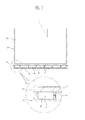
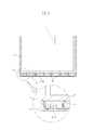
- FIG. 8 illustrates a cross-sectional view of a case according to still another embodiment.
- FIGS. 9A and 9B illustrate enlarged cross-sectional views of modified examples of the shock-absorbing cap of FIG. 8 .
- FIGS. 8 and 9 illustrate views in which the basic configuration is the same as that of the previous embodiment using both the shock-absorbing grooves and the shock-absorbing block, but a mounting structure for the shock absorbing block is modified.
- shock-absorbing grooves 42 may be formed on the shock-absorbing cap 30; and shock-absorbing blocks 46 may fill in the shock-absorbing grooves 42.
- shock initially applied to the shock-absorbing cap 30 may be transmitted to the shock-absorbing blocks 46 in the shock-absorbing grooves 42 while being distributed to the ribs 43 and the edge 34. Accordingly, a magnitude of the shock may be reduced by the self-shock absorbing properties of the shock-absorbing blocks 46.
- a load applied to the shock-absorbing cap 30 may be transferred to the ribs 43 and the edge 34 with the magnitude reduced by the shock-absorbing blocks 46. Then, the load may be transmitted to the case body 10 such that substantially the same shock-absorbing effect as the previous embodiment may be achieved.
- arrows shown in the ribs 43, edges 34, and shock-absorbing grooves 42/shock-absorbing blocks 46 represent a path of the shock applied to the shock-absorbing cap 30 and transmitted to the case body 10.
- the shock-absorber 40 has may have a structure including the shock-absorbing blocks 46 filled in the shock-absorbing grooves 42, it is possible to prevent a size of the secondary battery from being increased by a thickness of the shock-absorbing blocks 46 on the shock-absorbing cap 30, as in the previous embodiment.
- FIG. 9A illustrates one shock-absorbing groove 42 formed on the shock-absorbing cap 30 and the elastic shock-absorbing block 46 being seated in the shock-absorbing groove 42.
- FIG. 9B illustrates shock-absorbing grooves 42 formed at both side ends of the shock-absorbing cap 30 and shock-absorbing blocks 46, which may include, e.g., rubber, adhesives, or elastic members, in the shock-absorbing grooves 42.
- the embodiments may provide advantages over a structure in which a specific shock-absorbing member is provided, but a plate member is simply attached to the bottom of the case body by a label tape.
- shock applied to the bottom of the case body may be locally transmitted around edges of the bottom, thus avoiding adverse effects on the electrode assembly.
- shock applied to the bottom of the case may be dissipated not throughout the entire case but rather localized to edges and/or ribs. Thus, serious damage to the secondary battery itself may be prevented even when the shock is repeated.
- the embodiments provide a case for a secondary battery capable of preventing damage to a case body and an electrode assembly therein by including a sub-shock absorber in a shock-absorbing cap to improve shock-absorbing efficiency, when external shock is applied.
- the embodiments provide a case for a secondary battery capable of preventing damage to the case body and the electrode assembly therein and improving safety of the secondary battery by transferring shock applied to the shock-absorbing cap to ends thereof, rather than throughout the shock-absorbing cap, so that any damage to the case may be relegated to ends thereof.
- the embodiments may improve shock-absorbing efficiency when external shock is applied by including a sub-shock absorber in a shock-absorbing cap.
- a contact area between the shock-absorbing cap and the case body may be reduced by forming the sub-shock absorber in a groove on the shock-absorbing cap.
- load applied to the case body may be more attenuated by dispersing the shock throughout the shock-absorbing cap.
Landscapes
- Chemical & Material Sciences (AREA)
- Chemical Kinetics & Catalysis (AREA)
- Electrochemistry (AREA)
- General Chemical & Material Sciences (AREA)
- Sealing Battery Cases Or Jackets (AREA)
- Battery Mounting, Suspending (AREA)
Abstract
Description
- The present invention relates to a case for a secondary battery and a secondary battery including the same.
- As a variety of mobile devices have been widely used in recent years, many studies about secondary batteries used as power suppliers have been conducted.
- Secondary batteries include, e.g., a nickel-cadmium battery, a nickel-hydrogen battery, a nickel-zinc battery, and a lithium battery. Secondary batteries may have a basic structure in which a jelly-roll shaped electrode assembly with a separator between an anode and a cathode is sealed in a rectangular or a cylindrical case.
- Cases for the secondary batteries may include a cap assembly having an electrode terminal on the top of a case body accommodating the electrode assembly.
- Embodiments are directed to a case for a secondary battery and a secondary battery including the same.
- Embodiments include a case for a secondary battery, the case including a case body, the case body having bottom and a space for receiving an electrode assembly and a shock-absorbing cap, the shock-absorbing cap having a bottom and an edge extending from the bottom of the shock-absorbing cap, the edge being coupled to the bottom of the case body, wherein the shock-absorbing cap includes a sub-shock absorber, the sub-shock absorber being configured to distribute and transmit shock applied to the bottom of the shock-absorbing cap.
- The sub-shock absorber may include one or more shock-absorbing grooves on the shock-absorbing cap, the shock-absorbing grooves having a predetermined depth.
- The sub-shock absorber may include a plurality of the shock-absorbing grooves at regular intervals.
- Each of the plurality of shock-absorbing grooves may have the same area.
- The sub-shock absorber may include a plurality of the shock-absorbing grooves, the shock-absorbing grooves being symmetrically disposed at sides of a center of the shock-absorbing cap.
- The sub-shock absorber may include a plurality of the shock-absorbing grooves, the shock-absorbing grooves being disposed at opposite side ends of the shock-absorbing cap.
- The shock-absorbing cap may further include connection ribs between the shock-absorbing grooves, and the connection ribs and the edges of shock-absorbing cap may contact the bottom of the case body.
- The shock-absorbing cap may be made of polycarbonate.
- The case for a secondary battery may further include shock-absorbing blocks in the shock-absorbing grooves.
- The shock-absorbing blocks may include an elastic body, the elastic body having an elasticity greater than an elasticity of the shock-absorbing case.
- The elastic body may include any one of rubber and an adhesive.
- The shock-absorbing cap may have a thickness, and the predetermined depth may be about 50 % or less of the thickness of the shock-absorbing cap.
- The predetermined depth may be about 0.1 mm to about 0.25 mm.
- The shock-absorbing cap may further include one or more connecting protrusions on the edge of the shock-absorbing cap, the connecting protrusions extending along and covering a side of the bottom of the case body.
- The connection protrusions may be on a long side of the edge of the shock-absorbing cap.
- Embodiments of the invention also include a case for a secondary battery, the case including a case body, the case body having a bottom and a space for receiving and electrode assembly; a shock-absorbing cap, the shock-absorbing cap including a bottom, an edge extending from a side of the bottom of the shock-absorbing cap, the edge being coupled to the bottom of the case body, one or more connecting protrusions extending from long sides of the edge; and a specific shock-absorbing block on top of the shock-absorbing cap.
- The shock-absorbing cap may be made of any one of polycarbonate and polypropylene.
- The shock-absorbing block may be stacked on top of the shock-absorbing cap.
- The shock-absorbing block may be made of a material having an elasticity greater than an elasticity of the shock-absorbing cap.
- The shock-absorbing block may include any one of rubber and an adhesive.
- At least one of the above and other features and advantages may also be realized by providing a secondary battery including a case for a secondary battery according to an embodiment; an electrode assembly in the case; and a cap assembly connected with the electrode assembly and coupled to an upper end of a case body.
- The above and other features and advantages will become more apparent to those of ordinary skill in the art by describing in detail exemplary embodiments with reference to the attached drawings, in which:
-
FIG. 1 illustrates an exploded perspective view of a case according to an embodiment; -
FIG. 2 illustrates a cross-sectional view of an assembled state of the case ofFIG. 1 ; -
FIG. 3A illustrates a plan view of a shock-absorbing cap of the case ofFIG. 1 ; -
FIG. 3B illustrates a plan view of a modified example of the shock-absorbing cap ofFIG. 1 ; -
FIG. 3C illustrates a plan view of another modified example of the shock-absorbing cap ofFIG. 1 ; -
FIG. 3D illustrates a plan view of yet another modified example of the shock-absorbing cap ofFIG. 1 ; -
FIG. 4 illustrates an exploded perspective view of a case according to another embodiment; -
FIG. 5 illustrates a cross-sectional view of an assembled state of the case ofFIG. 4 ; -
FIG. 6 illustrates an exploded perspective view of a case according to yet another embodiment; -
FIG. 7 illustrates a cross-sectional view of an assembled state of the case ofFIG. 6 ; -
FIG. 8 illustrates a cross-sectional view of a case according to still another embodiment; -
FIG. 9A illustrates an enlarged cross-sectional view of a modified example of a shock-absorbing cap ofFIG. 8 ; and -
FIG. 9B illustrates an enlarged cross-sectional view of another modified example of a shock-absorbing cap ofFIG. 8 . - Example embodiments will now be described more fully hereinafter with reference to the accompanying drawings; however, they may be embodied in different forms and should not be construed as limited to the embodiments set forth herein. Rather, these embodiments are provided so that this disclosure will be thorough and complete, and will fully convey the scope of the invention to those skilled in the art.
- In the drawing figures, the dimensions of layers and regions may be exaggerated for clarity of illustration. It will also be understood that when a layer or element is referred to as being "on" another element, it can be directly on the other element, or intervening elements may also be present. In addition, it will also be understood that when an element is referred to as being "between" two elements, it can be the only element between the two elements, or one or more intervening elements may also be present. Like reference numerals refer to like elements throughout.
-
FIG. 1 illustrates an exploded perspective view of a case according to an embodiment.FIG. 2 illustrates a cross-sectional view of an assembled state of the case ofFIG. 1 .FIGS. 3A to 3D illustrate plan views of modified examples of a shock-absorbing cap ofFIG. 1 . - As shown in
FIGS. 1 and2 , a case for a secondary battery may include acase body 10, acase assembly 20, and a shock-absorbingcap 30 including a sub-shock absorber 40, which may also be referred to as primary and secondary shock absorbers (30, 40). - The
case body 10 may function as a case and an electrode for anelectrode assembly 50, it may have a receivingspace 12 for receiving theelectrode assembly 50 therein, and may have a box shape with a closed bottom and an open top for insertion of theelectrode assembly 50. - The
case body 10 may have e.g., a cylindrical or rectangular shape in accordance with a desired type of battery; and a rectangular shape is exemplified in the present embodiment. - The
electrode assembly 50 may be received in thecase body 10 and may substantially generate current in the secondary battery. Theelectrode assembly 50 may be wound in a jelly-roll shape. The jelly-rollshaped electrode assembly 50 may include an anode plate formed by coating an anode active material on an anode current collector, a cathode plate formed by coating a cathode active material on a cathode current collector, and a separator between the anode plate and the cathode plate to electrically connect them. - The
electrode assembly 50 may be connected with thecase body 10 and an anode terminal of the cap assembly 20 (described below). - The
electrode assembly 50 and thecap assembly 20 may have a structure well-known in the art, and they are not described and shown in the drawings in detail. The shock-absorbingcap 30 may be attached to the bottom of thecase body 10 equipped with theelectrode 50 and thecap assembly 20. The shock-absorbingcap 30 may be called a bottom case, but is referred to as the shock-absorbingcap 30 to discriminate from thecase body 10 of the secondary battery. The shock-absorbingcap 30 may include anedge 34 extending along a periphery of a bottom thereof. - The shock-absorbing
cap 30 may function as a protecting member that covers the bottom of thecase body 10 where a relatively large shock may be applied, e.g., when the secondary battery falls on the ground etc. The shock-absorbingcase 30 may have a simple plate shape having an area substantially the same as an area of the bottom of thecase body 10. A top of the shock-absorbingcap 30 may be in close contact with the bottom of thecase body 10. - The shock-absorbing
cap 30 may be made of a synthetic resin, e.g., PC (polycarbonate) or PP (polypropylene). However, any suitable materials may be selected and used, as long as they exhibit sufficient shock-absorbing properties. - The shock-absorbing
cap 30 may include connectingprotrusions 32 at front and rear edges thereof. The connectingprotrusions 32 may cover a lower outer or side surface of thecase body 10 when the shock-absorbingcap 30 is coupled with thecase body 10. The connectingprotrusions 32 may extend along long sides of theedge 34 coupled with thecase body 10. - It is possible to fix the shock-absorbing
cap 30 to thecase body 10 by attaching a label tape (not shown) thereto, e.g., to an outer surface of thecase body 10 and to the connectingprotrusions 32 in this position. - The shock-absorbing
cap 30 may include thesub-shock absorber 40 in order to increase shock-absorbing efficiency by transferring shock applied to the shock-absorbingcap 30 to an outer edge thereof. Thesub-shock absorber 40 may include a groove or recess (hereafter, referred to as 'shock-absorbing groove 42) on the shock-absorbingcap 30. - For example, the shock-absorbing
groove 42 may have a predetermined depth from a top of the shock-absorbingcap 30. A plurality of the shock-absorbinggrooves 42 may be arranged at regular intervals along an entire surface of the top of the shock-absorbingcap 30. The depth of the shock-absorbinggrooves 42 with respect to a thickness of the shock-absorbingcap 30 may have a greater effect on shock absorption than the number of shock-absorbinggrooves 42. In an implementation, the depth of the shock-absorbinggroove 42 may be within about 50 % of the thickness of the shock-absorbingcap 30. In other words, the depth of the shock-absorbinggroove 42 may be about 50 % or less of the thickness of the shock-absorbingcap 30. Maintaining the depth of the groove at about 50 % or less of the thickness of the shock-absorbingcap 30 may help ensure that the shock-absorbingcap 30 has sufficient strength. In an implementation, the depth may be about 0.1 mm to about 0.25 mm. Maintaining the depth at about 0.1 mm or greater may help ensure that shock-absorbing properties are not reduced. Maintaining the depth at about 0.25 mm or less may help ensure that the shock-absorbingcap 30 has sufficient strength. - As the plurality of shock-absorbing
grooves 42 are formed,ribs 43, which may serve as reinforcing members, may be correspondingly formed between the shock-absorbinggrooves 42. As shown inFIG. 2 , only an upper portion of theedge 34 and theribs 43 of the shock-absorbingcap 30 may contact the bottom of thecase body 10 when the shock-absorbingcap 30 is coupled with thecase body 10. - For example, a contact area between the shock-absorbing
cap 30 and thecase body 10 may be reduced, as compared with a case in which an entire surface of a shock-absorbing cap is in close contact with a case body. Accordingly, shock load applied to the shock-absorbingcap 30 may be transmitted only through theedge 34 and theribs 43. For example, arrows shown in theribs 43 andedges 34 represent a path of the shock applied to the shock-absorbingcap 30 and transmitted to thecase body 10. - In addition to the structure shown in
FIGS. 1 to 3A , in an implementation, two shock-absorbinggrooves 42 may be disposed to the left and right of the centre of the shock-absorbingcap 30, as shown inFIG. 3B . In another implementation, two shock-absorbinggrooves 42 may be disposed at left and right side ends of the shock-absorbingcap 30, as shown inFIG. 3C . For example, a large shock load due to falling, may be applied particularly to both side ends. Thus, it may be considerably effective to form the shock-absorbinggrooves 42 at both side ends. Further, areas of each of the shock-absorbinggrooves 42 may be the same. In an implementation, the shock-absorbingcap 30 may be symmetric with respect to the centre, in view of desired shock distribution. - In an implementation, the shock-absorbing
cap 30 may include one integral shock-absorbinggroove 42, as shown inFIG. 3D . In addition, the structure may be modified in various ways, as long as the contact area between the shock-absorbingcap 30 and thecase body 10 is reduced by the shock-absorbinggrooves 42. - As described above, the shock-absorbing
cap 30 may be made of a synthetic resin, e.g., PC (polycarbonate) or PP (polypropylene). However, polycarbonate may be preferable to polypropylene in terms of strength, for the shock-absorbinggrooves 42 in the structure of the present embodiment. - Next, operation and effects achieved in operation of the present embodiment having the above-described configuration will be described.
- If a complete product achieved by combining the
case body 10 with the shock-absorbingcap 30 having the shock-absorbinggrooves 42, as shown inFIG. 2 , accidentally falls or external shock is otherwise applied to the bottom of thecase body 10, the shock-absorbingcap 30 may primarily absorb the shock, such that the load may be reduced prior to being transmitted to thecase body 10. - As described above, the shock-absorbing
grooves 42 may be formed on the shock-absorbingcap 30. Thus, the shock load initially applied to the shock-absorbingcap 30 may be naturally dispersed throughout theribs 43 and theedge 34, except for the shock-absorbinggrooves 42. - For example, the load initially applied to the shock-absorbing
cap 30 may be transmitted to thecase body 10 only through theribs 43 and theedge 34. - Accordingly, the load transmitted through the
ribs 43 may be locally exerted on the bottom of thecase body 10; and the load dispersed to theedge 34 of the shock-absorbingcap 30 may be exerted on the edge of the bottom of thecase body 10. - As the load applied to the shock-absorbing
cap 30 may be locally transmitted to the bottom of thecase body 10 through theribs 43, as described above, the shock applied to thecase body 10 may be attenuated ore weakened, as compared with a case in which load is applied to a shock-absorbing cap and an entire bottom of a case body. - Further, since the
electrode assembly 50 may not be press-fitted in thecase body 10, but rather may include a space between theelectrode assembly 50 and an inner side of thecase body 10, as shown inFIG. 2 , if a load is transferred to theedge 34 of the shock-absorbingcap 30 and transmitted to the edge of the bottom of thecase body 10, the load exerted on the edge of thecase body 10 may not be directly transmitted to theelectrode assembly 50. - For example, the groove-shaped
sub-shock absorber 40 may be formed in the shock-absorbingcap 30 in the present embodiment. Thus, load applied to the shock-absorbingcap 30 may be transferred and concentrated to specific portions before being transmitted to thecase body 10. As a result, the load applied to thecase body 10 and theelectrode assembly 50 may be attenuated, thereby protecting a secondary battery including such a structure. -
FIG. 4 illustrates an exploded perspective view of a case according to another embodiment.FIG. 5 illustrates a cross-sectional view of an assembled state of the case ofFIG. 4. FIGS. 4 and5 illustrate another embodiment in which a basic design of forming asub-shock absorber 40 on a shock-absorbingcap 30 is the same as the previous embodiment. However, a difference includes asub-shock absorber 40 without shock-absorbinggrooves 42, but rather a specific plate. - For example, the
sub-shock absorber 40 according to the present embodiment may be formed of a simple rectangular plate, as shown inFIG. 4 . Accordingly, the shock-absorbingcap 30 may have a flat top. - For example, a shock-absorbing
block 46 may be formed of a plate having an area about the same as an area of a top of the shock-absorbingcap 30. In an implementation, the shock-absorbingblock 46 may be made of a material that is more elastic than the shock-absorbingcap 30. In an implementation, flexible materials, e.g., rubber, may be used and may have self-shock absorbing ability. - The shock-absorbing
block 46 may be stacked on top of the shock-absorbingcap 30 and may be between the top of the shock-absorbingcap 30 and the bottom of thecase body 10, when the shock-absorbingcap 30 is combined with thecase body 10, as shown inFIG. 5 . - In this configuration, the shock-absorbing
block 46 and the shock-absorbingcap 30 may be fixed by bonding and then coupled with thecase body 10. - Further, although the shock-absorbing
block 46 may be made of a flexible or elastic material, e.g., rubber, an adhesive, rather than the rubber, may function as a shock-absorbing block. In an implementation, a double shock-absorbing block may be implemented by applying an adhesive on the flexible material. - If an external shock is applied to a lower portion of the
case body 10, the load may be primarily attenuated by the shock-absorbingcap 30 and then secondarily attenuated by the shock-absorbingblock 46, before being transmitted to thecase body 10. - Accordingly, the load transmitted through the shock-absorbing
cap 30 may be exerted in thecase body 10, with a magnitude thereof sufficiently reduced. Thus, damage to thecase body 10 and theelectrode assembly 50 therein may be correspondingly reduced. - Although not illustrated, it is also possible to achieve higher shock-absorbing efficiency by using a plurality of stacked shock-absorbing
blocks 46. - For example, implementing the
sub-shock absorber 40 including the shock-absorbingblock 46 may not result in a change in design of the shock-absorbingcap 30. In particular, different from the previous embodiment, omitting formation of the shock-absorbinggrooves 42 on the shock-absorbingcap 30 may simplify manufacturing. - In addition, the present embodiment may achieve a load distribution effect due to, e.g., shock-absorbing grooves, as in the previous embodiment, when the load is transmitted through the shock-absorbing
block 46 that includes shock-absorbinggrooves 42 on the shock-absorbingblock 46. In this case, the shock-absorbinggrooves 42 may be formed through the shock-absorbingblock 46. -
FIG. 6 illustrates an exploded perspective view of a case according to yet another embodiment.FIG. 7 illustrates a cross-sectional view of an assembled state of the case ofFIG. 6 . For example,FIGS. 6 and7 illustrate views showing a case, which includes combined structures of the previous embodiments. - For example, the
sub-shock absorber 40 of the present embodiment may include the shock-absorbinggrooves 42 on the shock-absorbingcap 30 as well as the shock-absorbingblock 46 stacked on the top of the shock-absorbingcap 30. - In this configuration, the shape and number of the shock-absorbing
grooves 42 may be determined by modifications described with reference to the previous embodiments. In addition, the structure and material of the shock-absorbingblock 46 may be the same as in the previous embodiment. - With the
sub-shock absorber 40 included in the structure, as shown inFIG. 7 , load initially applied to the shock-absorbingcap 30 may be transferred and concentrated to the ribs 44 and theedge 34 by the shock-absorbinggroove 42 prior to being transmitted to the shock-absorbingblock 46. Then, the load may be attenuated again by the self-shock absorbing properties of the shock-absorbingblock 46 before being transmitted to thecase body 10. For example, arrows shown in theribs 43 andedges 34 represent a path of the shock applied to the shock-absorbingcap 30 and transmitted to the shock-absorbingblock 46. - For example, effects of shock-absorbing by the shock-absorbing
grooves 42 and the shock-absorbingblock 46 may be simultaneously achieved; and shock-absorbing efficiency may be increased. -
FIG. 8 illustrates a cross-sectional view of a case according to still another embodiment.FIGS. 9A and 9B illustrate enlarged cross-sectional views of modified examples of the shock-absorbing cap ofFIG. 8 . For example,FIGS. 8 and9 illustrate views in which the basic configuration is the same as that of the previous embodiment using both the shock-absorbing grooves and the shock-absorbing block, but a mounting structure for the shock absorbing block is modified. - For example, shock-absorbing
grooves 42 may be formed on the shock-absorbingcap 30; and shock-absorbingblocks 46 may fill in the shock-absorbinggrooves 42. - According to this structure, shock initially applied to the shock-absorbing
cap 30 may be transmitted to the shock-absorbingblocks 46 in the shock-absorbinggrooves 42 while being distributed to theribs 43 and theedge 34. Accordingly, a magnitude of the shock may be reduced by the self-shock absorbing properties of the shock-absorbingblocks 46. - For example, a load applied to the shock-absorbing
cap 30 may be transferred to theribs 43 and theedge 34 with the magnitude reduced by the shock-absorbingblocks 46. Then, the load may be transmitted to thecase body 10 such that substantially the same shock-absorbing effect as the previous embodiment may be achieved. For example, arrows shown in theribs 43, edges 34, and shock-absorbinggrooves 42/shock-absorbingblocks 46 represent a path of the shock applied to the shock-absorbingcap 30 and transmitted to thecase body 10. - As described above, since the shock-
absorber 40 has may have a structure including the shock-absorbingblocks 46 filled in the shock-absorbinggrooves 42, it is possible to prevent a size of the secondary battery from being increased by a thickness of the shock-absorbingblocks 46 on the shock-absorbingcap 30, as in the previous embodiment. -
FIG. 9A illustrates one shock-absorbinggroove 42 formed on the shock-absorbingcap 30 and the elastic shock-absorbingblock 46 being seated in the shock-absorbinggroove 42.FIG. 9B illustrates shock-absorbinggrooves 42 formed at both side ends of the shock-absorbingcap 30 and shock-absorbingblocks 46, which may include, e.g., rubber, adhesives, or elastic members, in the shock-absorbinggrooves 42. - The embodiments may provide advantages over a structure in which a specific shock-absorbing member is provided, but a plate member is simply attached to the bottom of the case body by a label tape. For example, according to the embodiments, when the secondary battery, e.g., falls, shock applied to the bottom of the case body may be locally transmitted around edges of the bottom, thus avoiding adverse effects on the electrode assembly. In particular, shock applied to the bottom of the case may be dissipated not throughout the entire case but rather localized to edges and/or ribs. Thus, serious damage to the secondary battery itself may be prevented even when the shock is repeated.
- The embodiments provide a case for a secondary battery capable of preventing damage to a case body and an electrode assembly therein by including a sub-shock absorber in a shock-absorbing cap to improve shock-absorbing efficiency, when external shock is applied.
- The embodiments provide a case for a secondary battery capable of preventing damage to the case body and the electrode assembly therein and improving safety of the secondary battery by transferring shock applied to the shock-absorbing cap to ends thereof, rather than throughout the shock-absorbing cap, so that any damage to the case may be relegated to ends thereof.
- The embodiments may improve shock-absorbing efficiency when external shock is applied by including a sub-shock absorber in a shock-absorbing cap.
- For example, a contact area between the shock-absorbing cap and the case body may be reduced by forming the sub-shock absorber in a groove on the shock-absorbing cap. Thus, load applied to the case body may be more attenuated by dispersing the shock throughout the shock-absorbing cap.
- Further, it is possible to reduce shock transmission to the case body by implementing the sub-shock absorber in a flexible plate.
- Exemplary embodiments have been disclosed herein, and although specific terms are employed, they are used and are to be interpreted in a generic and descriptive sense only and not for purpose of limitation. Accordingly, it will be understood by those of ordinary skill in the art that various changes in form and details may be made without departing from the scope of the present invention as set forth in the following claims.
Claims (15)
- A case for a secondary battery, the case comprising:a case body (10) having a space for receiving an electrode assembly; anda shock-absorbing cap (30) coupled to the bottom of the case body,wherein the shock-absorbing cap (30) includes a secondary shock absorber (40), the secondary shock absorber being configured to distribute and transmit shock applied to the bottom of the shock-absorbing cap (30).
- The case as claimed in claim 1, wherein the secondary shock absorber (40) includes one or more shock-absorbing recesses (42) on the shock-absorbing cap.
- The case as claimed in claim 2, wherein the secondary shock absorber includes a plurality of the shock-absorbing recesses at regular intervals.
- The case as claimed in claim 3, wherein each of the plurality of shock-absorbing recesses has the same area.
- The case as claimed in claim 2, wherein the secondary shock absorber includes a plurality of the shock-absorbing recesses, the shock-absorbing recesses being symmetrically disposed about the centre of the shock-absorbing cap.
- The case as claimed in claim 2, wherein the secondary shock absorber includes a plurality of the shock-absorbing recesses, the shock-absorbing recesses being disposed at opposite side ends of the shock-absorbing cap.
- The case as claimed in claim 2, 3 or 4, wherein:the shock-absorbing cap further includes connection ribs between the shock-absorbing recesses, andthe connection ribs (43) and the edges (34) of the shock-absorbing cap contact the bottom of the case body.
- The case as claimed in any one of claims 2 to 7, further comprising shock-absorbing blocks (46) in the shock-absorbing recesses (42).
- The case as claimed in claim 8, wherein the shock-absorbing blocks include an elastic body, the elastic body having an elasticity greater than an elasticity of the shock-absorbing case.
- The case as claimed in claim 9, wherein the elastic body includes a rubber and/or an adhesive.
- The case as claimed in any one of claims 2 to 10, wherein the depth of the shock-absorbing recesses is about 50 % or less of the thickness of the shock-absorbing cap.
- The case as claimed in claim 11, wherein the depth is about 0.1 mm to about 0.25 mm.
- The case as claimed in any one of the preceding claims, wherein the shock-absorbing cap further includes one or more connecting protrusions (32) on the edges of the shock-absorbing cap, the connecting protrusions extending along and covering a side of the bottom of the case body, wherein the connecting protrusions may be on a long side of the edge of the shock-absorbing cap.
- The case as claimed in any one of the preceding claims, wherein the secondary shock absorber (40) comprises a shock-absorbing block (46) on top of the shock-absorbing cap.
- The case as claimed in claim 14, wherein the shock-absorbing block is made of a material having an elasticity greater than an elasticity of the shock-absorbing cap.
Applications Claiming Priority (1)
| Application Number | Priority Date | Filing Date | Title |
|---|---|---|---|
| KR1020100066860A KR101199108B1 (en) | 2010-07-12 | 2010-07-12 | case of secondary battery and secondary battery thereof |
Publications (3)
| Publication Number | Publication Date |
|---|---|
| EP2408040A2 true EP2408040A2 (en) | 2012-01-18 |
| EP2408040A3 EP2408040A3 (en) | 2013-10-16 |
| EP2408040B1 EP2408040B1 (en) | 2019-06-12 |
Family
ID=44503584
Family Applications (1)
| Application Number | Title | Priority Date | Filing Date |
|---|---|---|---|
| EP11173222.8A Active EP2408040B1 (en) | 2010-07-12 | 2011-07-08 | Case for a secondary battery |
Country Status (5)
| Country | Link |
|---|---|
| US (1) | US20120009463A1 (en) |
| EP (1) | EP2408040B1 (en) |
| JP (1) | JP5412403B2 (en) |
| KR (1) | KR101199108B1 (en) |
| CN (1) | CN102332540B (en) |
Families Citing this family (17)
| Publication number | Priority date | Publication date | Assignee | Title |
|---|---|---|---|---|
| EP3236397A1 (en) | 2007-05-18 | 2017-10-25 | 3M Innovative Properties Company | Verfahren zur verfolgung von method for tracking procedures performed on personal protection equipment and actions of individuals |
| USD669427S1 (en) * | 2012-01-10 | 2012-10-23 | Research In Motion Limited | Electronic device battery |
| US9495227B2 (en) * | 2012-02-10 | 2016-11-15 | Twilio, Inc. | System and method for managing concurrent events |
| KR101192619B1 (en) * | 2012-03-23 | 2012-10-18 | 주식회사 엘지화학 | Battery case |
| US9716253B2 (en) | 2012-03-23 | 2017-07-25 | Lg Chem, Ltd. | Battery case for secondary battery |
| KR101382035B1 (en) * | 2012-08-08 | 2014-04-14 | 세방전지(주) | Battery case with anti-vibration structure |
| KR102211365B1 (en) * | 2014-04-14 | 2021-02-03 | 삼성에스디아이 주식회사 | Secondary battery |
| KR102388922B1 (en) * | 2018-02-22 | 2022-04-21 | 삼성에스디아이 주식회사 | Tray for secondary battery and Jig for forming thereof |
| US10588175B1 (en) | 2018-10-24 | 2020-03-10 | Capital One Services, Llc | Network of trust with blockchain |
| CN209071424U (en) * | 2018-11-16 | 2019-07-05 | 宁德时代新能源科技股份有限公司 | For accommodating the cabinet and battery case of battery modules |
| JP7245044B2 (en) * | 2018-12-25 | 2023-03-23 | 本田技研工業株式会社 | Solid-state battery cell structure and solid-state battery manufacturing method |
| KR102483426B1 (en) * | 2020-08-18 | 2022-12-30 | 한국앤컴퍼니 주식회사 | Manufacturing method of manufacturing AGM storage battery crack prevention case |
| KR102724271B1 (en) * | 2021-12-24 | 2024-10-31 | 주식회사 호원 | Structure for absorbing shock of battery pack case for electric vehicle |
| KR102936714B1 (en) * | 2022-01-13 | 2026-03-09 | 주식회사 엘지에너지솔루션 | Battery Pack Assembly With Absorbing Impact, Apparatus And Method For Manufacturing The Same |
| JP7710478B2 (en) * | 2023-01-31 | 2025-07-18 | プライムプラネットエナジー&ソリューションズ株式会社 | Battery module and manufacturing method thereof |
| KR102666721B1 (en) * | 2023-08-31 | 2024-05-16 | 이강용 | Battery storage container with seismic structure |
| KR102912927B1 (en) * | 2023-09-22 | 2026-01-14 | 한국앤컴퍼니 주식회사 | Lead-acid battery manufacturing method that improves vibration resistance using a vibration-absorbing support |
Family Cites Families (12)
| Publication number | Priority date | Publication date | Assignee | Title |
|---|---|---|---|---|
| JP3887145B2 (en) * | 2000-05-25 | 2007-02-28 | 矢崎総業株式会社 | Battery cover shock absorption structure |
| KR100601513B1 (en) * | 2004-10-01 | 2006-07-19 | 삼성에스디아이 주식회사 | Lithium secondary battery |
| JP4946068B2 (en) * | 2005-01-21 | 2012-06-06 | ソニー株式会社 | Battery pack |
| JP2008166060A (en) * | 2006-12-27 | 2008-07-17 | Sanyo Electric Co Ltd | Battery pack |
| JP2008186750A (en) * | 2007-01-31 | 2008-08-14 | Nok Corp | Cushioning material |
| US8252441B2 (en) * | 2007-08-31 | 2012-08-28 | Micro Power Electronics, Inc. | Spacers for fixing battery cells within a battery package casing and associated systems and methods |
| US8999536B2 (en) * | 2008-06-20 | 2015-04-07 | Samsung Sdi Co., Ltd. | Battery pack |
| KR101002506B1 (en) * | 2008-09-18 | 2010-12-17 | 삼성에스디아이 주식회사 | Lithium secondary battery |
| KR101084982B1 (en) * | 2008-10-14 | 2011-11-18 | 주식회사 엘지화학 | New rechargeable battery pack |
| CN201311945Y (en) * | 2008-12-15 | 2009-09-16 | 江苏新日电动车股份有限公司 | Combined electric vehicle battery box |
| KR101023910B1 (en) * | 2008-12-22 | 2011-03-22 | 삼성에스디아이 주식회사 | Battery pack |
| DE202009015040U1 (en) * | 2009-10-20 | 2010-01-21 | Ips Integrated Power Solutions Ag | Module and system for an electrochemical battery cell |
-
2010
- 2010-07-12 KR KR1020100066860A patent/KR101199108B1/en active Active
- 2010-11-08 JP JP2010249743A patent/JP5412403B2/en active Active
-
2011
- 2011-07-08 EP EP11173222.8A patent/EP2408040B1/en active Active
- 2011-07-12 CN CN201110195362.7A patent/CN102332540B/en active Active
- 2011-07-12 US US13/180,770 patent/US20120009463A1/en not_active Abandoned
Non-Patent Citations (1)
| Title |
|---|
| None |
Also Published As
| Publication number | Publication date |
|---|---|
| EP2408040B1 (en) | 2019-06-12 |
| KR101199108B1 (en) | 2012-11-09 |
| KR20120006235A (en) | 2012-01-18 |
| JP2012023009A (en) | 2012-02-02 |
| CN102332540A (en) | 2012-01-25 |
| EP2408040A3 (en) | 2013-10-16 |
| US20120009463A1 (en) | 2012-01-12 |
| JP5412403B2 (en) | 2014-02-12 |
| CN102332540B (en) | 2014-11-05 |
Similar Documents
| Publication | Publication Date | Title |
|---|---|---|
| EP2408040B1 (en) | Case for a secondary battery | |
| JP6730431B2 (en) | Battery module, battery pack including the same, automobile | |
| KR101827493B1 (en) | Battery module with improved safety and life cycle | |
| EP2523234B1 (en) | Battery module and method for manufacturing the battery module | |
| EP3654407B1 (en) | Casing for accomodating battery module and battery pack | |
| EP3113244B1 (en) | Secondary battery and fabricating method thereof | |
| US20120219851A1 (en) | Pouch-type secondary battery | |
| KR20140070445A (en) | Electrochemical cell | |
| KR102071592B1 (en) | Rechargeable battery | |
| KR102263200B1 (en) | Battery Pack | |
| KR102931523B1 (en) | Batteries, battery packs, and vehicles | |
| KR102018692B1 (en) | Rechargeable battery and method of manufacturing the same | |
| KR20160144325A (en) | Electrode lead and secondary battery including the same | |
| KR101741123B1 (en) | Battery Cell Having Through Hole | |
| KR101825007B1 (en) | Pouch type secondary battery and method of fabricating the same | |
| KR102261182B1 (en) | Cell Assembly and Battery Module Having the Same | |
| KR102097083B1 (en) | Battery pack case and battery pack including the battery pack case, car | |
| US20250070423A1 (en) | Secondary Battery with Improved Terminal Structure | |
| JP2026501403A (en) | Battery module | |
| JP6507803B2 (en) | Battery module | |
| KR20190093993A (en) | Flexible battery and the method of manufacturing it | |
| US20130295427A1 (en) | Electrochemical cell | |
| US20250279525A1 (en) | Battery pack | |
| US20150072173A1 (en) | Rechargeable battery pack | |
| KR20140109694A (en) | Rechargeable battery pack |
Legal Events
| Date | Code | Title | Description |
|---|---|---|---|
| AK | Designated contracting states |
Kind code of ref document: A2 Designated state(s): AL AT BE BG CH CY CZ DE DK EE ES FI FR GB GR HR HU IE IS IT LI LT LU LV MC MK MT NL NO PL PT RO RS SE SI SK SM TR |
|
| AX | Request for extension of the european patent |
Extension state: BA ME |
|
| PUAI | Public reference made under article 153(3) epc to a published international application that has entered the european phase |
Free format text: ORIGINAL CODE: 0009012 |
|
| 17P | Request for examination filed |
Effective date: 20120321 |
|
| RIN1 | Information on inventor provided before grant (corrected) |
Inventor name: LEE, SANG-JOON |
|
| PUAL | Search report despatched |
Free format text: ORIGINAL CODE: 0009013 |
|
| AK | Designated contracting states |
Kind code of ref document: A3 Designated state(s): AL AT BE BG CH CY CZ DE DK EE ES FI FR GB GR HR HU IE IS IT LI LT LU LV MC MK MT NL NO PL PT RO RS SE SI SK SM TR |
|
| AX | Request for extension of the european patent |
Extension state: BA ME |
|
| RIC1 | Information provided on ipc code assigned before grant |
Ipc: H01M 2/02 20060101AFI20130912BHEP Ipc: H01M 2/10 20060101ALI20130912BHEP Ipc: H01M 2/04 20060101ALI20130912BHEP |
|
| STAA | Information on the status of an ep patent application or granted ep patent |
Free format text: STATUS: EXAMINATION IS IN PROGRESS |
|
| 17Q | First examination report despatched |
Effective date: 20170503 |
|
| REG | Reference to a national code |
Ref country code: DE Ref legal event code: R079 Ref document number: 602011059574 Country of ref document: DE Free format text: PREVIOUS MAIN CLASS: H01M0002020000 Ipc: H01M0002100000 |
|
| GRAP | Despatch of communication of intention to grant a patent |
Free format text: ORIGINAL CODE: EPIDOSNIGR1 |
|
| STAA | Information on the status of an ep patent application or granted ep patent |
Free format text: STATUS: GRANT OF PATENT IS INTENDED |
|
| RIC1 | Information provided on ipc code assigned before grant |
Ipc: H01M 2/02 20060101ALN20181130BHEP Ipc: H01M 2/04 20060101ALI20181130BHEP Ipc: H01M 2/10 20060101AFI20181130BHEP |
|
| INTG | Intention to grant announced |
Effective date: 20190102 |
|
| GRAS | Grant fee paid |
Free format text: ORIGINAL CODE: EPIDOSNIGR3 |
|
| GRAA | (expected) grant |
Free format text: ORIGINAL CODE: 0009210 |
|
| STAA | Information on the status of an ep patent application or granted ep patent |
Free format text: STATUS: THE PATENT HAS BEEN GRANTED |
|
| AK | Designated contracting states |
Kind code of ref document: B1 Designated state(s): AL AT BE BG CH CY CZ DE DK EE ES FI FR GB GR HR HU IE IS IT LI LT LU LV MC MK MT NL NO PL PT RO RS SE SI SK SM TR |
|
| RAP1 | Party data changed (applicant data changed or rights of an application transferred) |
Owner name: SAMSUNG SDI CO., LTD. |
|
| REG | Reference to a national code |
Ref country code: GB Ref legal event code: FG4D |
|
| REG | Reference to a national code |
Ref country code: CH Ref legal event code: EP |
|
| REG | Reference to a national code |
Ref country code: AT Ref legal event code: REF Ref document number: 1143759 Country of ref document: AT Kind code of ref document: T Effective date: 20190615 |
|
| REG | Reference to a national code |
Ref country code: DE Ref legal event code: R096 Ref document number: 602011059574 Country of ref document: DE |
|
| REG | Reference to a national code |
Ref country code: IE Ref legal event code: FG4D |
|
| REG | Reference to a national code |
Ref country code: NL Ref legal event code: MP Effective date: 20190612 |
|
| REG | Reference to a national code |
Ref country code: LT Ref legal event code: MG4D |
|
| PG25 | Lapsed in a contracting state [announced via postgrant information from national office to epo] |
Ref country code: LT Free format text: LAPSE BECAUSE OF FAILURE TO SUBMIT A TRANSLATION OF THE DESCRIPTION OR TO PAY THE FEE WITHIN THE PRESCRIBED TIME-LIMIT Effective date: 20190612 Ref country code: HR Free format text: LAPSE BECAUSE OF FAILURE TO SUBMIT A TRANSLATION OF THE DESCRIPTION OR TO PAY THE FEE WITHIN THE PRESCRIBED TIME-LIMIT Effective date: 20190612 Ref country code: FI Free format text: LAPSE BECAUSE OF FAILURE TO SUBMIT A TRANSLATION OF THE DESCRIPTION OR TO PAY THE FEE WITHIN THE PRESCRIBED TIME-LIMIT Effective date: 20190612 Ref country code: AL Free format text: LAPSE BECAUSE OF FAILURE TO SUBMIT A TRANSLATION OF THE DESCRIPTION OR TO PAY THE FEE WITHIN THE PRESCRIBED TIME-LIMIT Effective date: 20190612 Ref country code: SE Free format text: LAPSE BECAUSE OF FAILURE TO SUBMIT A TRANSLATION OF THE DESCRIPTION OR TO PAY THE FEE WITHIN THE PRESCRIBED TIME-LIMIT Effective date: 20190612 Ref country code: NO Free format text: LAPSE BECAUSE OF FAILURE TO SUBMIT A TRANSLATION OF THE DESCRIPTION OR TO PAY THE FEE WITHIN THE PRESCRIBED TIME-LIMIT Effective date: 20190912 Ref country code: ES Free format text: LAPSE BECAUSE OF FAILURE TO SUBMIT A TRANSLATION OF THE DESCRIPTION OR TO PAY THE FEE WITHIN THE PRESCRIBED TIME-LIMIT Effective date: 20190612 |
|
| PG25 | Lapsed in a contracting state [announced via postgrant information from national office to epo] |
Ref country code: GR Free format text: LAPSE BECAUSE OF FAILURE TO SUBMIT A TRANSLATION OF THE DESCRIPTION OR TO PAY THE FEE WITHIN THE PRESCRIBED TIME-LIMIT Effective date: 20190913 Ref country code: RS Free format text: LAPSE BECAUSE OF FAILURE TO SUBMIT A TRANSLATION OF THE DESCRIPTION OR TO PAY THE FEE WITHIN THE PRESCRIBED TIME-LIMIT Effective date: 20190612 Ref country code: BG Free format text: LAPSE BECAUSE OF FAILURE TO SUBMIT A TRANSLATION OF THE DESCRIPTION OR TO PAY THE FEE WITHIN THE PRESCRIBED TIME-LIMIT Effective date: 20190912 Ref country code: LV Free format text: LAPSE BECAUSE OF FAILURE TO SUBMIT A TRANSLATION OF THE DESCRIPTION OR TO PAY THE FEE WITHIN THE PRESCRIBED TIME-LIMIT Effective date: 20190612 |
|
| REG | Reference to a national code |
Ref country code: AT Ref legal event code: MK05 Ref document number: 1143759 Country of ref document: AT Kind code of ref document: T Effective date: 20190612 |
|
| PG25 | Lapsed in a contracting state [announced via postgrant information from national office to epo] |
Ref country code: EE Free format text: LAPSE BECAUSE OF FAILURE TO SUBMIT A TRANSLATION OF THE DESCRIPTION OR TO PAY THE FEE WITHIN THE PRESCRIBED TIME-LIMIT Effective date: 20190612 Ref country code: AT Free format text: LAPSE BECAUSE OF FAILURE TO SUBMIT A TRANSLATION OF THE DESCRIPTION OR TO PAY THE FEE WITHIN THE PRESCRIBED TIME-LIMIT Effective date: 20190612 Ref country code: SK Free format text: LAPSE BECAUSE OF FAILURE TO SUBMIT A TRANSLATION OF THE DESCRIPTION OR TO PAY THE FEE WITHIN THE PRESCRIBED TIME-LIMIT Effective date: 20190612 Ref country code: PT Free format text: LAPSE BECAUSE OF FAILURE TO SUBMIT A TRANSLATION OF THE DESCRIPTION OR TO PAY THE FEE WITHIN THE PRESCRIBED TIME-LIMIT Effective date: 20191014 Ref country code: RO Free format text: LAPSE BECAUSE OF FAILURE TO SUBMIT A TRANSLATION OF THE DESCRIPTION OR TO PAY THE FEE WITHIN THE PRESCRIBED TIME-LIMIT Effective date: 20190612 Ref country code: NL Free format text: LAPSE BECAUSE OF FAILURE TO SUBMIT A TRANSLATION OF THE DESCRIPTION OR TO PAY THE FEE WITHIN THE PRESCRIBED TIME-LIMIT Effective date: 20190612 Ref country code: CZ Free format text: LAPSE BECAUSE OF FAILURE TO SUBMIT A TRANSLATION OF THE DESCRIPTION OR TO PAY THE FEE WITHIN THE PRESCRIBED TIME-LIMIT Effective date: 20190612 |
|
| PG25 | Lapsed in a contracting state [announced via postgrant information from national office to epo] |
Ref country code: IS Free format text: LAPSE BECAUSE OF FAILURE TO SUBMIT A TRANSLATION OF THE DESCRIPTION OR TO PAY THE FEE WITHIN THE PRESCRIBED TIME-LIMIT Effective date: 20191012 Ref country code: SM Free format text: LAPSE BECAUSE OF FAILURE TO SUBMIT A TRANSLATION OF THE DESCRIPTION OR TO PAY THE FEE WITHIN THE PRESCRIBED TIME-LIMIT Effective date: 20190612 Ref country code: IT Free format text: LAPSE BECAUSE OF FAILURE TO SUBMIT A TRANSLATION OF THE DESCRIPTION OR TO PAY THE FEE WITHIN THE PRESCRIBED TIME-LIMIT Effective date: 20190612 |
|
| REG | Reference to a national code |
Ref country code: CH Ref legal event code: PL |
|
| REG | Reference to a national code |
Ref country code: DE Ref legal event code: R097 Ref document number: 602011059574 Country of ref document: DE |
|
| PG25 | Lapsed in a contracting state [announced via postgrant information from national office to epo] |
Ref country code: MC Free format text: LAPSE BECAUSE OF FAILURE TO SUBMIT A TRANSLATION OF THE DESCRIPTION OR TO PAY THE FEE WITHIN THE PRESCRIBED TIME-LIMIT Effective date: 20190612 Ref country code: TR Free format text: LAPSE BECAUSE OF FAILURE TO SUBMIT A TRANSLATION OF THE DESCRIPTION OR TO PAY THE FEE WITHIN THE PRESCRIBED TIME-LIMIT Effective date: 20190612 |
|
| REG | Reference to a national code |
Ref country code: BE Ref legal event code: MM Effective date: 20190731 |
|
| PLBE | No opposition filed within time limit |
Free format text: ORIGINAL CODE: 0009261 |
|
| STAA | Information on the status of an ep patent application or granted ep patent |
Free format text: STATUS: NO OPPOSITION FILED WITHIN TIME LIMIT |
|
| PG25 | Lapsed in a contracting state [announced via postgrant information from national office to epo] |
Ref country code: DK Free format text: LAPSE BECAUSE OF FAILURE TO SUBMIT A TRANSLATION OF THE DESCRIPTION OR TO PAY THE FEE WITHIN THE PRESCRIBED TIME-LIMIT Effective date: 20190612 Ref country code: PL Free format text: LAPSE BECAUSE OF FAILURE TO SUBMIT A TRANSLATION OF THE DESCRIPTION OR TO PAY THE FEE WITHIN THE PRESCRIBED TIME-LIMIT Effective date: 20190612 |
|
| 26N | No opposition filed |
Effective date: 20200313 |
|
| PG25 | Lapsed in a contracting state [announced via postgrant information from national office to epo] |
Ref country code: IS Free format text: LAPSE BECAUSE OF FAILURE TO SUBMIT A TRANSLATION OF THE DESCRIPTION OR TO PAY THE FEE WITHIN THE PRESCRIBED TIME-LIMIT Effective date: 20200224 Ref country code: LU Free format text: LAPSE BECAUSE OF NON-PAYMENT OF DUE FEES Effective date: 20190708 Ref country code: CH Free format text: LAPSE BECAUSE OF NON-PAYMENT OF DUE FEES Effective date: 20190731 Ref country code: LI Free format text: LAPSE BECAUSE OF NON-PAYMENT OF DUE FEES Effective date: 20190731 Ref country code: SI Free format text: LAPSE BECAUSE OF FAILURE TO SUBMIT A TRANSLATION OF THE DESCRIPTION OR TO PAY THE FEE WITHIN THE PRESCRIBED TIME-LIMIT Effective date: 20190612 Ref country code: BE Free format text: LAPSE BECAUSE OF NON-PAYMENT OF DUE FEES Effective date: 20190731 |
|
| PG2D | Information on lapse in contracting state deleted |
Ref country code: IS |
|
| PG25 | Lapsed in a contracting state [announced via postgrant information from national office to epo] |
Ref country code: IE Free format text: LAPSE BECAUSE OF NON-PAYMENT OF DUE FEES Effective date: 20190708 Ref country code: IS Free format text: LAPSE BECAUSE OF FAILURE TO SUBMIT A TRANSLATION OF THE DESCRIPTION OR TO PAY THE FEE WITHIN THE PRESCRIBED TIME-LIMIT Effective date: 20191112 |
|
| REG | Reference to a national code |
Ref country code: DE Ref legal event code: R079 Ref document number: 602011059574 Country of ref document: DE Free format text: PREVIOUS MAIN CLASS: H01M0002100000 Ipc: H01M0050200000 |
|
| PG25 | Lapsed in a contracting state [announced via postgrant information from national office to epo] |
Ref country code: CY Free format text: LAPSE BECAUSE OF FAILURE TO SUBMIT A TRANSLATION OF THE DESCRIPTION OR TO PAY THE FEE WITHIN THE PRESCRIBED TIME-LIMIT Effective date: 20190612 |
|
| PG25 | Lapsed in a contracting state [announced via postgrant information from national office to epo] |
Ref country code: HU Free format text: LAPSE BECAUSE OF FAILURE TO SUBMIT A TRANSLATION OF THE DESCRIPTION OR TO PAY THE FEE WITHIN THE PRESCRIBED TIME-LIMIT; INVALID AB INITIO Effective date: 20110708 Ref country code: MT Free format text: LAPSE BECAUSE OF FAILURE TO SUBMIT A TRANSLATION OF THE DESCRIPTION OR TO PAY THE FEE WITHIN THE PRESCRIBED TIME-LIMIT Effective date: 20190612 |
|
| PG25 | Lapsed in a contracting state [announced via postgrant information from national office to epo] |
Ref country code: MK Free format text: LAPSE BECAUSE OF FAILURE TO SUBMIT A TRANSLATION OF THE DESCRIPTION OR TO PAY THE FEE WITHIN THE PRESCRIBED TIME-LIMIT Effective date: 20190612 |
|
| P01 | Opt-out of the competence of the unified patent court (upc) registered |
Effective date: 20230528 |
|
| PGFP | Annual fee paid to national office [announced via postgrant information from national office to epo] |
Ref country code: GB Payment date: 20250626 Year of fee payment: 15 |
|
| PGFP | Annual fee paid to national office [announced via postgrant information from national office to epo] |
Ref country code: FR Payment date: 20250623 Year of fee payment: 15 |
|
| PGFP | Annual fee paid to national office [announced via postgrant information from national office to epo] |
Ref country code: DE Payment date: 20250624 Year of fee payment: 15 |