EP2408033A2 - Power generation device - Google Patents
Power generation device Download PDFInfo
- Publication number
- EP2408033A2 EP2408033A2 EP11173598A EP11173598A EP2408033A2 EP 2408033 A2 EP2408033 A2 EP 2408033A2 EP 11173598 A EP11173598 A EP 11173598A EP 11173598 A EP11173598 A EP 11173598A EP 2408033 A2 EP2408033 A2 EP 2408033A2
- Authority
- EP
- European Patent Office
- Prior art keywords
- fluid
- thermomagnetic
- power generation
- generation device
- fluids
- Prior art date
- Legal status (The legal status is an assumption and is not a legal conclusion. Google has not performed a legal analysis and makes no representation as to the accuracy of the status listed.)
- Granted
Links
- 238000010248 power generation Methods 0.000 title claims abstract description 41
- 239000012530 fluid Substances 0.000 claims abstract description 207
- 239000000463 material Substances 0.000 claims description 57
- XLYOFNOQVPJJNP-UHFFFAOYSA-N water Substances O XLYOFNOQVPJJNP-UHFFFAOYSA-N 0.000 claims description 43
- 238000011084 recovery Methods 0.000 claims description 5
- 239000007789 gas Substances 0.000 claims description 3
- 239000007788 liquid Substances 0.000 claims description 3
- 239000000203 mixture Substances 0.000 claims 1
- 230000035699 permeability Effects 0.000 description 21
- 238000010586 diagram Methods 0.000 description 10
- 230000000694 effects Effects 0.000 description 4
- 230000036961 partial effect Effects 0.000 description 4
- 230000002829 reductive effect Effects 0.000 description 4
- 239000002918 waste heat Substances 0.000 description 4
- 230000009471 action Effects 0.000 description 3
- 230000008901 benefit Effects 0.000 description 2
- 230000005540 biological transmission Effects 0.000 description 2
- 230000008859 change Effects 0.000 description 2
- 239000008188 pellet Substances 0.000 description 2
- 239000002699 waste material Substances 0.000 description 2
- 241000282414 Homo sapiens Species 0.000 description 1
- 230000002411 adverse Effects 0.000 description 1
- 230000015556 catabolic process Effects 0.000 description 1
- 230000005611 electricity Effects 0.000 description 1
- 238000003912 environmental pollution Methods 0.000 description 1
- 239000012535 impurity Substances 0.000 description 1
- 238000007689 inspection Methods 0.000 description 1
- 238000004519 manufacturing process Methods 0.000 description 1
- 230000007246 mechanism Effects 0.000 description 1
- 230000001681 protective effect Effects 0.000 description 1
- 230000002441 reversible effect Effects 0.000 description 1
Images


Classifications
-
- H—ELECTRICITY
- H10—SEMICONDUCTOR DEVICES; ELECTRIC SOLID-STATE DEVICES NOT OTHERWISE PROVIDED FOR
- H10N—ELECTRIC SOLID-STATE DEVICES NOT OTHERWISE PROVIDED FOR
- H10N15/00—Thermoelectric devices without a junction of dissimilar materials; Thermomagnetic devices, e.g. using the Nernst-Ettingshausen effect
- H10N15/20—Thermomagnetic devices using thermal change of the magnetic permeability, e.g. working above and below the Curie point
-
- H—ELECTRICITY
- H02—GENERATION; CONVERSION OR DISTRIBUTION OF ELECTRIC POWER
- H02N—ELECTRIC MACHINES NOT OTHERWISE PROVIDED FOR
- H02N10/00—Electric motors using thermal effects
Definitions
- the present disclosure relates to energy supply, and more particularly, power generation devices.
- the magnetocaloric effect (MCE, from magnet and calorie) is a magneto-thermodynamic phenomenon in which a reversible change in temperature of a suitable material is caused by exposing the material to a changing magnetic field.
- Thermodynamic cycles that take advantage of the magnetocaloric effect can be in wide use.
- the present disclosure is directed to power generation devices for providing electric power by utilizing the magnetocaloric effect.
- a power generation device includes a plurality of thermomagnetic generators and a flow controller.
- Each of the thermomagnetic generators includes a thermomagnetic material, a coil and a fluidic mixer.
- the coil surrounds the thermomagnetic material.
- the fluidic mixer can mix a first fluid with the second fluid and can output the mixed fluid to the thermomagnetic material, wherein a fluid temperature of the first fluid is different from a fluid temperature of the second fluid.
- the flow controller can control flow rates of the second fluids flowing into the thermomagnetic generators respectively.
- a power generation device includes a plurality of thermomagnetic generator and a flow controller.
- the thermomagnetic generators can acquire first fluids respectively.
- the flow controller can control flow rates of the second fluids flowing into the thermomagnetic generators respectively, wherein a fluid temperature of the first fluid is different from a fluid temperature of the second fluid.
- the flow rates of the second fluids flowing into the respective thermomagnetic generators are changed by means of the flow controller, and therefore a temperature of the mixed fluid that flows to each thermomagnetic material is changed, so that the thermomagnetic material can alternate between a permeability and a non-permeability (or between a high permeability and a low permeability) according as sufficiently low and high temperature of the mixed fluid is applied by turns.
- the coil can be induced to generate power.
- the power generation device further comprises at least one third fluid.
- the fluidic mixer mixes the first fluid, the second fluid and the third fluid for outputting the mixed fluid to the thermomagnetic material.
- a fluid temperature of the third fluid is different from the fluid temperature of the first fluid and the fluid temperature of the second fluid.
- Each of the third fluids has a different temperature, respectively.
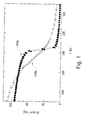
- Fig. 1 shows the absolute temperature along the x-axis of the plot and the magnetic reluctivity for the thermomagnetic materials 200a and 200b along the y-axis.
- the first thermomagnetic material 200a or the second thermomagnetic material 200b can act as a high permeability material or a low permeability material by slightly controlling temperature variation.
- the thermomagnetic material can be low permeability when the thermomagnetic material is heated to reach a sufficiently high temperature.
- the thermomagnetic material can be high permeability when the thermomagnetic material is cooled to reach a sufficiently low temperature.
- Lenz's law is a common way of understanding how electromagnetic circuits must always obey Newton's third law. Accordingly, a coil can be used for surrounding the thermomagnetic material and thereby generate an induced current when the thermomagnetic material rapidly alternates between high permeability and low permeability.
- thermomagnetic material may be applied to or removed from the thermomagnetic material by means of fluid flow, so as to control the temperature variation of the thermomagnetic material.
- fluid flow may be applied to or removed from the thermomagnetic material by means of fluid flow, so as to control the temperature variation of the thermomagnetic material.
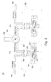
- Fig. 2 is a schematic diagram of a power generation device 100 according to one embodiment of the present disclosure.
- the power generation device 100 includes a plurality of thermomagnetic generators 200 and a flow controller 300.
- the thermomagnetic generators 200 can acquire first fluids respectively.
- the flow controller 300 can control flow rates of the second fluids flowing into the respective thermomagnetic generators, wherein a fluid temperature of the first fluid is different from a fluid temperature of the second fluid.
- Each of the thermomagnetic generators 200 includes a thermomagnetic material 210, a coil 220 and a fluidic mixer 230.
- the coil 220 surrounds the thermomagnetic material 210.
- the fluidic mixer 230 can mix a first fluid with the second fluid and can output the mixed fluid to the thermomagnetic material 210.
- the fluidic mixer 230 may be a length of piping where the first and second fluids flow together.
- thermomagnetic generators 200 the flow rates of the second fluids flowing into the respective thermomagnetic generators 200 are changed by means of the flow controller 300, and therefore a temperature of the mixed fluid that flows to each thermomagnetic material 210 is changed, so that the thermomagnetic material can alternate between high permeability and a low permeability according as alternate low and high temperature of the mixed fluid.
- the coil 220 can be induced to generate power.
- the first and second fluids may be liquids, so as to facilitate transportation.
- the first fluid is relatively hot water
- the second fluid is relatively cold water.
- the first and second fluids may be gas or the like.
- the power generation device 100 includes a plurality of first fluid conduits 400, a plurality of second fluid conduits 410 and a third fluid conduit 420.
- the first fluid conduits 400 are connected to the thermomagnetic generators 200 respectively, so as to deliver the first fluids to the thermomagnetic generators 200 respectively.
- the second fluid conduits 410 are connected from the flow controller 300 to the thermomagnetic generators respectively, so as to deliver the second fluids to the thermomagnetic generators 300 respectively.
- the third fluid conduit 420 is connected to the flow controller 300, so as to deliver the second fluids into the flow controller 300.
- the first fluids flow into the respective thermomagnetic generators 200 via the first fluid conduits 400.
- the flow controller 300 acquires a total amount of the second fluids and then delivers the second fluids to the respective thermomagnetic generators 300.
- each of the thermomagnetic generators 200 includes a first check valve 240 and a second check valve 242.
- the first check valve 240 is disposed between the first fluid conduit 400 and the fluidic mixer 230 and is connected to the first fluid conduit 400 and the fluidic mixer 230;
- the second check valve 242 is disposed between the second fluid conduit 410 and the fluidic mixer 230 and is connected to the second fluid conduit 410 and the fluidic mixer 230.
- the first check valve 240 allows the first fluid into the fluidic mixer 230;
- the second check valve 242 allows the second fluid into the fluidic mixer 230.
- the mixed fluid cannot reversely flow from the fluidic mixer 230 to the first fluid conduit 400 and/or the second fluid conduit 410.
- thermomagnetic generator 200 In control experiment, electromagnetic pumps or solenoid valves would be added to the thermomagnetic generator 200 if the flow controller 300 and the third fluid conduit 420 are canceled.
- each thermomagnetic generator 200 needs two electromagnetic pumps or two solenoid valves, wherein one electromagnetic pump or solenoid valve lets the first fluid in the first fluid conduit 400 totally flow into the thermomagnetic generator 200 or completely blocks the first fluid in the first fluid conduit 400 from flowing into the thermomagnetic generator 200, and the other electromagnetic pump or solenoid valve lets the second fluid in the second fluid conduit 410 totally flow into the thermomagnetic generator 200 or completely blocks the second fluid of the second fluid conduit 410 from flowing into the thermomagnetic generator 200.
- thermomagnetic material 210 can be changed by alternate hot and cold water.
- the switching action of the electromagnetic pump or solenoid valve is too slow.
- its switching action wastes more time and power.
- the solenoid valve may have a breakdown for exceeding this limitation.
- the electromagnetic pump and solenoid valve each waste electric power; however, the power generation device 100 is used for outputting electricity. Therefore, the use of the electromagnetic pump or solenoid valve diverges from the objective of the power generation device 100.
- the flow controller 300 guides and distributes fluid to the respective thermomagnetic generators 200 without completely cut off fluid flow into the thermomagnetic generator 200.
- the problems of mechanical friction and power dissipation are generally reduced, solved or circumvented by using the flow controller 300.
- the power generation device 100 has two thermomagnetic generators 200.
- the first fluid is hot water
- the second fluid is cold water.
- the flow controller 300 can guide and distributes a more portion of the cold water to the right thermomagnetic generator 200 and a less portion of the cold water to the left thermomagnetic generator 200.
- the left thermomagnetic generator 200 mixes the hot water with the less portion of the cold water, in which this mixed water reaches a relatively high temperature, so that the left thermomagnetic material 210 can become low permeability; the right thermomagnetic generator 200 mixes the hot water with the more portion of the cold water, in which this mixed water reaches a relatively low temperature, so that the right thermomagnetic material 210 can become high permeability.
- the flow controller 300 can guide and distributes a more portion of the cold water to the left thermomagnetic generator 200 and a less portion of the cold water to the right thermomagnetic generator 200.
- thermomagnetic generator 200 mixes the hot water with the less portion of the cold water, in which this mixed water reaches a relatively high temperature, so that the right thermomagnetic material 210 can become low permeability; the left thermomagnetic generator 200 mixes the hot water with the more portion of the cold water, in which this mixed water reaches a relatively low temperature, so that the left thermomagnetic material 210 can become high permeability. Then, the aforesaid steps may be repeated in an iterative manner. Thus, each thermomagnetic generator 200 can be induced to generate power by means of alternate hotter and colder water flowing into the thermomagnetic generator 200.
- the thermomagnetic material 210 can be changed into high permeability or low permeability by controlling temperature variation from 10°C to 15 °C.
- the first fluid is hot water, and the fluid temperature of the first fluid is 50°C; the second fluid is cold water, and the fluid temperature of the second fluid is 15°C.
- the constant flow rate of the hot water is 1 L/sec.
- the flow controller 300 can guide and distributes a more portion of the cold water to the right thermomagnetic generator 200 and a less portion of the cold water to the left thermomagnetic generator 200, wherein a flow rate of the more portion of the cold water is 4 L/sec, and a flow rate of the less portion of the cold water is 1 L/sec.
- the flow controller 300 can guide and distributes a more portion of the cold water to the left thermomagnetic generator 200 and a less portion of the cold water to the right thermomagnetic generator 200, wherein a flow rate of the more portion of the cold water is 4 L/sec, and a flow rate of the less portion of the cold water is 1 L/sec.
- the flow rate of the hot water being 1 L/sec is constant, and therefore the temperature of the mixed water can become 32.5°C when the flow rate of the cold water is 1 L/sec, alternatively, the temperature of the mixed water can become 22°C when the flow rate of the cold water is 4 L/sec.
- the thermomagnetic material 210 can be changed into high permeability or low permeability due to the sufficient temperature variation that is about 10.5°C.
- thermomagnetic generator 300 may be associated with two or more thermomagnetic generators.
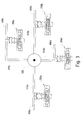
- Fig. 3 is a schematic diagram of a power generation device according to another embodiment of the present disclosure. As shown in Fig. 3 , this power generation device includes a flow controller 300, four thermomagnetic generators 200a, 200b, 200c and 200d, four first fluid conduits 400a, 400b, 400c and 400d, and four second fluid conduits 410a, 410b, 410c and 410d.
- thermomagnetic generator 200a, 200b, 200c and 200d each are essentially the same as the thermomagnetic generator 200 shown in Fig. 1 .
- the first fluid conduits 400a, 400b, 400c and 400d each are essentially the same as the first fluid conduit 400 shown in Fig. 1 .
- the second fluid conduits 410a, 410b, 410c and 410d each are essentially the same as the second fluid conduit 410 shown in Fig. 1 .
- the first fluid conduits 400a, 400b, 400c and 400d deliver the first fluids to the thermomagnetic generator 200a, 200b, 200c and 200d respectively.
- the controller 300 can control the second fluids flowing into some thermomagnetic generators and adjust flow rates of the second fluids flowing into these thermomagnetic generators respectively.
- the flow controller 300 can let the second fluids flow into the thermomagnetic generator 200a and 200b via the second fluid conduits 400a and 400b and adjust the flow rates of the second fluids flowing into the respective thermomagnetic generators 200a and 200b; alternatively, the flow controller 300 can let the second fluids flow into the thermomagnetic generator 200c and 200d via the second fluid conduits 400c and 400d and adjust the flow rates of the second fluids flowing into the respective thermomagnetic generators 200c and 200d.
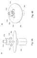
- Fig. 4A is a pictorial drawing of the flow controller 300 of Fig. 2 according to one embodiment of the present disclosure.
- Fig. 4B is a partial perspective drawing of the flow controller 300 of Fig. 4A .
- the flow controller 300 includes a flow splitter 310a, a control valve 320a and a motor 330a, where the flow splitter 310a has an inlet port 312a and a plurality of outlet ports 314a.
- the motor 330a is a kind of mechanical power device.
- the flow splitter 310a As to the flow splitter 310a, its inlet port 312a is connected to the third fluid conduit 420 (shown in Fig. 2 ) for receiving the second fluid, so that the flow splitter 310a can acquire a total amount of the second fluids.
- the outlet ports 314a are connected to the second fluid conduits 410 (shown in Fig. 2 ) respectively, so as to split the second fluids into the respective thermomagnetic generators 200.
- the control valve 320a is configured in the flow splitter 310a, and the motor 330a is connected to the control valve 320a.
- the motor 330a drives the control valve 320a, so as to adjust the flow rates of the second fluids flowing from the outlet ports 314a into the thermomagnetic generators 200 respectively.
- control valve 320a is an eccentric.
- the motor 330a drives the eccentric to change a direction of the working fluid.
- the direction of the working fluid is changed rapidly because the rotation rate of the motor can reach 1000 or more revolutions per minute (RPM).
- the flow controller 300 may include a flywheel 340a.
- the flywheel 340a is disposed between the control valve 320a and the motor 330a, and the motor 330a is connected to the control valve 320a via an axle center of the flywheel 340a.
- the torsion and instability of the motor 330a can be reduced by means of the flywheel 340a.
- Fig. 5A is a pictorial drawing of the flow controller 300 of Fig. 2 according to another embodiment of the present disclosure.
- Fig. 5B is a partial perspective drawing of the flow controller 300 of Fig. 5A .
- the flow controller 300 includes a flow splitter 310b, a control valve 320b and a motor 330b, where the flow splitter 310b has an inlet port 312b and a plurality of outlet ports 314b.
- the flow splitter 310b As to the flow splitter 310b, its inlet port 312b is connected to the third fluid conduit 420 (shown in Fig. 2 ) for receiving the second fluid, so that the flow splitter 310b can acquire a total amount of the second fluids.
- the outlet ports 314b are connected to the second fluid conduits 410 (shown in Fig. 2 ) respectively, so as to split the second fluids into the respective thermomagnetic generators 200.
- the control valve 320b is configured in the flow splitter 310b, and the motor 330b is connected to the control valve 320b.
- the motor 330a drives the control valve 320b, so as to adjust the flow rates of the second fluids flowing from the outlet ports 314b into the thermomagnetic generators 200 respectively.
- the flow controller 300 may include a flywheel 340a.
- the flywheel 340b is disposed between the control valve 320b and the motor 330b, and the motor 330b is connected to the control valve 320b via an axle center of the flywheel 340b.
- the torsion and instability of the motor 330b can be reduced by means of the flywheel 340b.
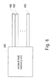
- Fig. 6 is a block diagram of an exhaust heat recovery unit 500 according to one embodiment of the present disclosure.
- the exhaust heat recovery unit 500 can recycle the waste heat and output the first fluid that is heated by the recycled waste heat.
- the first fluid conduits 400 each acquire the first fluid from the exhaust heat recovery unit 500, wherein the fluid temperature of the first fluid is higher than the fluid temperature of the second fluid.
- the thermomagnetic generator 200 can receive hotter fluid from the first fluid conduit 400.
- the first fluid may be heated by means of terrestrial heat, so as to provide hotter fluid for the thermomagnetic generator 200.
- thermomagnetic generators may further include at least one magnet and at least one yoke.
- the magnet, the yoke and the thermomagnetic material constitute a closed magnetic circuit.
- the magnet is a permanent magnet or an electric magnet.
- Fig. 7A is a schematic diagram of a thermomagnetic generator 200 of Fig. 2 according to one embodiment of the present disclosure.
- the thermomagnetic generator 200 includes two separate magnets 250 and two separate yokes 260.
- the two magnets 250 and the thermomagnetic material 210 are disposed between the two yokes 260.
- the opposing sides of each of the two yokes 260 are connected to the two magnets 250 respectively, and a central part of each of the two yokes 260 is connected to the thermomagnetic material 210. Therefore, the magnets 250, the yokes 260 and the thermomagnetic material 210 constitute a closed magnetic circuit.
- the magnetic line of force is created along the closed magnetic circuit, so that magnetic energy is sufficiently utilized for increasing the power generation efficiency of the thermomagnetic generator.
- the coil 220 may be a superconducting coil for reducing transmission loss.
- the thermomagnetic generator 200 may include a cryostat 600.
- the cryostat 600 adjusts a temperature of the superconducting coil, so that the superconducting coil can be maintained at ultra-low temperature.
- the superconducting coil at ultra-low temperature has very small resistance or approximately zero-resistance.
- Fig. 7B is a schematic diagram of a thermomagnetic generator of Fig. 2 according to another embodiment of the present disclosure.
- the thermomagnetic generator 200 includes two separate magnets 250 and a single yoke 260.
- the two magnets 250 are connected to opposing sides of the thermomagnetic material 210 respectively, and two ends of the yoke 260 clamp and are connected to the two magnets 250 respectively. Therefore, the magnets 250, the yoke 260 and the thermomagnetic material 210 constitute a closed magnetic circuit.
- the magnetic line of force is created along the closed magnetic circuit, so that magnetic energy is sufficiently utilized for increasing the power generation efficiency of the thermomagnetic generator.
- the coil 220 may be a superconducting coil for reducing transmission loss.
- the thermomagnetic generator 200 may include a cryostat 600 for maintaining the superconducting coil at a low temperature.
- the form of the thermomagnetic material 210 may be a plurality of pellets or masses.
- the fluid can flow through small opening or space between these pellets or masses.
- the surface of the thermomagnetic material 210 may be coated with a protective film; alternatively, the thermomagnetic material 210 is disposed within the sealed container, and therefore the fluid flows to the sealed container without affecting the thermomagnetic material 210.
Landscapes
- Connection Of Motors, Electrical Generators, Mechanical Devices, And The Like (AREA)
- Control Of Eletrric Generators (AREA)
- Other Liquid Machine Or Engine Such As Wave Power Use (AREA)
Abstract
Description
- The present disclosure relates to energy supply, and more particularly, power generation devices.
- The magnetocaloric effect (MCE, from magnet and calorie) is a magneto-thermodynamic phenomenon in which a reversible change in temperature of a suitable material is caused by exposing the material to a changing magnetic field.
- Thermodynamic cycles that take advantage of the magnetocaloric effect can be in wide use. For human beings that suffer from environmental pollution and energy shortage, there is an urgent need in the related field to provide power by utilizing the magnetocaloric effect.
- The following presents a simplified summary of the disclosure in order to provide a basic understanding to the reader. This summary is not an extensive overview of the disclosure and it does not identify key/critical elements of the present invention or delineate the scope of the present invention. Its sole purpose is to present some concepts disclosed herein in a simplified form as a prelude to the more detailed description that is presented later.
- In one or more various aspects, the present disclosure is directed to power generation devices for providing electric power by utilizing the magnetocaloric effect.
- According to one embodiment of the present invention, a power generation device includes a plurality of thermomagnetic generators and a flow controller. Each of the thermomagnetic generators includes a thermomagnetic material, a coil and a fluidic mixer. The coil surrounds the thermomagnetic material. The fluidic mixer can mix a first fluid with the second fluid and can output the mixed fluid to the thermomagnetic material, wherein a fluid temperature of the first fluid is different from a fluid temperature of the second fluid. The flow controller can control flow rates of the second fluids flowing into the thermomagnetic generators respectively.
- According to another embodiment of the present invention, a power generation device includes a plurality of thermomagnetic generator and a flow controller. The thermomagnetic generators can acquire first fluids respectively. The flow controller can control flow rates of the second fluids flowing into the thermomagnetic generators respectively, wherein a fluid temperature of the first fluid is different from a fluid temperature of the second fluid.
- In use, the flow rates of the second fluids flowing into the respective thermomagnetic generators are changed by means of the flow controller, and therefore a temperature of the mixed fluid that flows to each thermomagnetic material is changed, so that the thermomagnetic material can alternate between a permeability and a non-permeability (or between a high permeability and a low permeability) according as sufficiently low and high temperature of the mixed fluid is applied by turns. Thus, the coil can be induced to generate power.
- The power generation device further comprises at least one third fluid. The fluidic mixer mixes the first fluid, the second fluid and the third fluid for outputting the mixed fluid to the thermomagnetic material. A fluid temperature of the third fluid is different from the fluid temperature of the first fluid and the fluid temperature of the second fluid. Each of the third fluids has a different temperature, respectively.
- Technical advantages are generally achieved, by embodiments of the present invention, as follows:
- 1. It is no need to use electromagnetic valves to block fluid. Therefore, energy saving can be accomplished; and
- 2. The electromagnetic pump or solenoid valve must completely cut off fluid flow, which results in serious mechanical friction and power dissipation. The flow controller guides and distributes fluid to the respective thermomagnetic generators without completely cut off fluid flow into the thermomagnetic generator. Thus, the problems of mechanical friction and power dissipation are generally reduced, solved or circumvented by using the flow controller.
- Many of the attendant features will be more readily appreciated, as the same becomes better understood by reference to the following detailed description considered in connection with the accompanying drawings.
- The present description will be better understood from the following detailed description read in light of the accompanying drawings, wherein:
-
Fig. 1 shows the absolute temperature along the x-axis of the plot and the permeability values for the thermomagnetic materials along the y-axis; -
Fig. 2 is a schematic diagram of a power generation device according to one embodiment of the present disclosure; -
Fig. 3 is a schematic diagram of a power generation device according to another embodiment of the present disclosure; -
Fig. 4A is a pictorial drawing of a flow controller ofFig. 2 according to one embodiment of the present disclosure; -
Fig. 4B is a partial perspective drawing of the flow controller ofFig. 4A ; -
Fig. 5A is a pictorial drawing of a flow controller ofFig. 2 according to another embodiment of the present disclosure; -
Fig. 5B is a partial perspective drawing of the flow controller ofFig. 5A ; -
Fig. 6 is a block diagram of an exhaust heat recovery unit according to one embodiment of the present disclosure; -
Fig. 7A is a schematic diagram of a thermomagnetic generator ofFig. 2 according to one embodiment of the present disclosure; and -
Fig. 7B is a schematic diagram of a thermomagnetic generator ofFig. 2 according to another embodiment of the present disclosure. - In the following detailed description, for purposes of explanation, numerous specific details are set forth in order to attain a thorough understanding of the disclosed embodiments. It will be apparent, however, that one or more embodiments may be practiced without these specific details. In other instances, well-known structures and devices are schematically shown in order to simplify the drawings.
- As used in the description herein and throughout the claims that follow, the meaning of "a", "an", and "the" includes reference to the plural unless the context clearly dictates otherwise. Also, as used in the description herein and throughout the claims that follow, the terms "comprise or comprising", "include or including", "have or having", "contain or containing" and the like are to be understood to be open-ended, i.e., to mean including but not limited to. As used in the description herein and throughout the claims that follow, the meaning of "in" includes "in" and "on" unless the context clearly dictates otherwise.
- It will be understood that, although the terms first, second, etc. may be used herein to describe various elements, these elements should not be limited by these terms. These terms are only used to distinguish one element from another. For example, a first element could be termed a second element, and, similarly, a second element could be termed a first element, without departing from the scope of the embodiments. As used herein, the term "and/or" includes any and all combinations of one or more of the associated listed items.
- It will be understood that when an element is referred to as being "connected" or "coupled" to another element, it can be directly connected or coupled to the other element or intervening elements may be present. In contrast, when an element is referred to as being "directly connected" or "directly coupled" to another element, there are no intervening elements present.
- Unless otherwise defined, all terms (including technical and scientific terms) used herein have the same meaning as commonly understood by one of ordinary skill in the art to which example embodiments belong. It will be further understood that terms, such as those defined in commonly used dictionaries, should be interpreted as having a meaning that is consistent with their meaning in the context of the relevant art and will not be interpreted in an idealized or overly formal sense unless expressly so defined herein.
-
Fig. 1 shows the absolute temperature along the x-axis of the plot and the magnetic reluctivity for thethermomagnetic materials Fig. 1 , the firstthermomagnetic material 200a or the secondthermomagnetic material 200b can act as a high permeability material or a low permeability material by slightly controlling temperature variation. In magnetic field, the thermomagnetic material can be low permeability when the thermomagnetic material is heated to reach a sufficiently high temperature. Alternatively, in magnetic field, the thermomagnetic material can be high permeability when the thermomagnetic material is cooled to reach a sufficiently low temperature. Lenz's law is a common way of understanding how electromagnetic circuits must always obey Newton's third law. Accordingly, a coil can be used for surrounding the thermomagnetic material and thereby generate an induced current when the thermomagnetic material rapidly alternates between high permeability and low permeability. - In practice, heat may be applied to or removed from the thermomagnetic material by means of fluid flow, so as to control the temperature variation of the thermomagnetic material. For a more complete understanding of a mechanism of controlling fluid, please refer to
Fig. 2 . -
Fig. 2 is a schematic diagram of apower generation device 100 according to one embodiment of the present disclosure. As shown inFig. 2 , thepower generation device 100 includes a plurality ofthermomagnetic generators 200 and aflow controller 300. Thethermomagnetic generators 200 can acquire first fluids respectively. Theflow controller 300 can control flow rates of the second fluids flowing into the respective thermomagnetic generators, wherein a fluid temperature of the first fluid is different from a fluid temperature of the second fluid. - Each of the
thermomagnetic generators 200 includes athermomagnetic material 210, acoil 220 and afluidic mixer 230. Thecoil 220 surrounds thethermomagnetic material 210. Thefluidic mixer 230 can mix a first fluid with the second fluid and can output the mixed fluid to thethermomagnetic material 210. For example, thefluidic mixer 230 may be a length of piping where the first and second fluids flow together. - In this way, the flow rates of the second fluids flowing into the respective
thermomagnetic generators 200 are changed by means of theflow controller 300, and therefore a temperature of the mixed fluid that flows to eachthermomagnetic material 210 is changed, so that the thermomagnetic material can alternate between high permeability and a low permeability according as alternate low and high temperature of the mixed fluid. Thus, thecoil 220 can be induced to generate power. - In this embodiment, the first and second fluids may be liquids, so as to facilitate transportation. For example, the first fluid is relatively hot water, and the second fluid is relatively cold water. Alternatively, in another embodiment, the first and second fluids may be gas or the like.
- For a more complete understanding of transporting the first and second fluids, refer to
Fig. 2 . As shown inFig. 1 , thepower generation device 100 includes a plurality of firstfluid conduits 400, a plurality of secondfluid conduits 410 and a thirdfluid conduit 420. - The first
fluid conduits 400 are connected to thethermomagnetic generators 200 respectively, so as to deliver the first fluids to thethermomagnetic generators 200 respectively. The secondfluid conduits 410 are connected from theflow controller 300 to the thermomagnetic generators respectively, so as to deliver the second fluids to thethermomagnetic generators 300 respectively. The thirdfluid conduit 420 is connected to theflow controller 300, so as to deliver the second fluids into theflow controller 300. - In use, the first fluids flow into the respective
thermomagnetic generators 200 via the firstfluid conduits 400. Theflow controller 300 acquires a total amount of the second fluids and then delivers the second fluids to the respectivethermomagnetic generators 300. - For avoiding a backflow of the
thermomagnetic generator 200, each of thethermomagnetic generators 200 includes afirst check valve 240 and asecond check valve 242. Thefirst check valve 240 is disposed between the firstfluid conduit 400 and thefluidic mixer 230 and is connected to the firstfluid conduit 400 and thefluidic mixer 230; thesecond check valve 242 is disposed between the secondfluid conduit 410 and thefluidic mixer 230 and is connected to the secondfluid conduit 410 and thefluidic mixer 230. In use, thefirst check valve 240 allows the first fluid into thefluidic mixer 230; thesecond check valve 242 allows the second fluid into thefluidic mixer 230. Thus, the mixed fluid cannot reversely flow from thefluidic mixer 230 to the firstfluid conduit 400 and/or the secondfluid conduit 410. - In control experiment, electromagnetic pumps or solenoid valves would be added to the
thermomagnetic generator 200 if theflow controller 300 and the thirdfluid conduit 420 are canceled. Specifically, eachthermomagnetic generator 200 needs two electromagnetic pumps or two solenoid valves, wherein one electromagnetic pump or solenoid valve lets the first fluid in the firstfluid conduit 400 totally flow into thethermomagnetic generator 200 or completely blocks the first fluid in the firstfluid conduit 400 from flowing into thethermomagnetic generator 200, and the other electromagnetic pump or solenoid valve lets the second fluid in the secondfluid conduit 410 totally flow into thethermomagnetic generator 200 or completely blocks the second fluid of the secondfluid conduit 410 from flowing into thethermomagnetic generator 200. - For example, when one solenoid valve lets hot water in the first
fluid conduit 400 flow into thethermomagnetic generator 200, the other solenoid valve blocks cold water of the secondfluid conduit 410 from flowing into thethermomagnetic generator 200. On the contrary, when one solenoid valve blocks the hot water of the firstfluid conduit 400 from flowing into thethermomagnetic generator 200, the other solenoid valve lets the cold water in the secondfluid conduit 410 flow into thethermomagnetic generator 200. Thus, thethermomagnetic material 210 can be changed by alternate hot and cold water. - However, the switching action of the electromagnetic pump or solenoid valve is too slow. For a large-sized electromagnetic pump or solenoid valve, its switching action wastes more time and power. Moreover, it is difficult to cut off fluid completely when the fluid is too large. Because the number of the switching action of the solenoid valve is limited, the solenoid valve may have a breakdown for exceeding this limitation. In use, the electromagnetic pump and solenoid valve each waste electric power; however, the
power generation device 100 is used for outputting electricity. Therefore, the use of the electromagnetic pump or solenoid valve diverges from the objective of thepower generation device 100. - In view of the foregoing reason, there is no need to use electromagnetic pumps or solenoid valves to block fluid. The electromagnetic pump or solenoid valve must completely cut off fluid flow, which results in serious mechanical friction and power dissipation. In this embodiment, the
flow controller 300 guides and distributes fluid to the respectivethermomagnetic generators 200 without completely cut off fluid flow into thethermomagnetic generator 200. Thus, the problems of mechanical friction and power dissipation are generally reduced, solved or circumvented by using theflow controller 300. - In
Fig. 2 , thepower generation device 100 has twothermomagnetic generators 200. In one embodiment, the first fluid is hot water, and the second fluid is cold water. In one step, theflow controller 300 can guide and distributes a more portion of the cold water to the rightthermomagnetic generator 200 and a less portion of the cold water to the leftthermomagnetic generator 200. Therefore, the leftthermomagnetic generator 200 mixes the hot water with the less portion of the cold water, in which this mixed water reaches a relatively high temperature, so that the leftthermomagnetic material 210 can become low permeability; the rightthermomagnetic generator 200 mixes the hot water with the more portion of the cold water, in which this mixed water reaches a relatively low temperature, so that the rightthermomagnetic material 210 can become high permeability. In the next step, theflow controller 300 can guide and distributes a more portion of the cold water to the leftthermomagnetic generator 200 and a less portion of the cold water to the rightthermomagnetic generator 200. Therefore, the rightthermomagnetic generator 200 mixes the hot water with the less portion of the cold water, in which this mixed water reaches a relatively high temperature, so that the rightthermomagnetic material 210 can become low permeability; the leftthermomagnetic generator 200 mixes the hot water with the more portion of the cold water, in which this mixed water reaches a relatively low temperature, so that the leftthermomagnetic material 210 can become high permeability. Then, the aforesaid steps may be repeated in an iterative manner. Thus, eachthermomagnetic generator 200 can be induced to generate power by means of alternate hotter and colder water flowing into thethermomagnetic generator 200. - For example, the
thermomagnetic material 210 can be changed into high permeability or low permeability by controlling temperature variation from 10°C to 15 °C. In one embodiment, the first fluid is hot water, and the fluid temperature of the first fluid is 50°C; the second fluid is cold water, and the fluid temperature of the second fluid is 15°C. The constant flow rate of the hot water is 1 L/sec. Theflow controller 300 can guide and distributes a more portion of the cold water to the rightthermomagnetic generator 200 and a less portion of the cold water to the leftthermomagnetic generator 200, wherein a flow rate of the more portion of the cold water is 4 L/sec, and a flow rate of the less portion of the cold water is 1 L/sec. Alternatively, theflow controller 300 can guide and distributes a more portion of the cold water to the leftthermomagnetic generator 200 and a less portion of the cold water to the rightthermomagnetic generator 200, wherein a flow rate of the more portion of the cold water is 4 L/sec, and a flow rate of the less portion of the cold water is 1 L/sec. For eachthermomagnetic generator 200, the flow rate of the hot water being 1 L/sec is constant, and therefore the temperature of the mixed water can become 32.5°C when the flow rate of the cold water is 1 L/sec, alternatively, the temperature of the mixed water can become 22°C when the flow rate of the cold water is 4 L/sec. Thus, thethermomagnetic material 210 can be changed into high permeability or low permeability due to the sufficient temperature variation that is about 10.5°C. - Furthermore, one
flow controller 300 may be associated with two or more thermomagnetic generators. Refer toFig. 3. Fig. 3 is a schematic diagram of a power generation device according to another embodiment of the present disclosure. As shown inFig. 3 , this power generation device includes aflow controller 300, fourthermomagnetic generators first fluid conduits second fluid conduits - In this embodiment, the
thermomagnetic generator thermomagnetic generator 200 shown inFig. 1 . Thefirst fluid conduits fluid conduit 400 shown inFig. 1 . Thesecond fluid conduits fluid conduit 410 shown inFig. 1 . - In use, the
first fluid conduits thermomagnetic generator controller 300 can control the second fluids flowing into some thermomagnetic generators and adjust flow rates of the second fluids flowing into these thermomagnetic generators respectively. - For example, the
flow controller 300 can let the second fluids flow into thethermomagnetic generator second fluid conduits thermomagnetic generators flow controller 300 can let the second fluids flow into thethermomagnetic generator fluid conduits thermomagnetic generators - For a more complete understanding of the
flow controller 300, refer toFigs. 4A-4B and5A-5B .Fig. 4A is a pictorial drawing of theflow controller 300 ofFig. 2 according to one embodiment of the present disclosure.Fig. 4B is a partial perspective drawing of theflow controller 300 ofFig. 4A . - As shown in
Figs. 4A-4B , theflow controller 300 includes aflow splitter 310a, acontrol valve 320a and amotor 330a, where theflow splitter 310a has aninlet port 312a and a plurality ofoutlet ports 314a. Themotor 330a is a kind of mechanical power device. - As to the
flow splitter 310a, itsinlet port 312a is connected to the third fluid conduit 420 (shown inFig. 2 ) for receiving the second fluid, so that theflow splitter 310a can acquire a total amount of the second fluids. Theoutlet ports 314a are connected to the second fluid conduits 410 (shown inFig. 2 ) respectively, so as to split the second fluids into the respectivethermomagnetic generators 200. - As shown in
Fig. 4B , thecontrol valve 320a is configured in theflow splitter 310a, and themotor 330a is connected to thecontrol valve 320a. In use, themotor 330a drives thecontrol valve 320a, so as to adjust the flow rates of the second fluids flowing from theoutlet ports 314a into thethermomagnetic generators 200 respectively. - In this embodiment, the
control valve 320a is an eccentric. Themotor 330a drives the eccentric to change a direction of the working fluid. The direction of the working fluid is changed rapidly because the rotation rate of the motor can reach 1000 or more revolutions per minute (RPM). - As shown in
Figs. 4A-4B , theflow controller 300 may include aflywheel 340a. Theflywheel 340a is disposed between thecontrol valve 320a and themotor 330a, and themotor 330a is connected to thecontrol valve 320a via an axle center of theflywheel 340a. During themotor 330a is operating, the torsion and instability of themotor 330a can be reduced by means of theflywheel 340a. -
Fig. 5A is a pictorial drawing of theflow controller 300 ofFig. 2 according to another embodiment of the present disclosure.Fig. 5B is a partial perspective drawing of theflow controller 300 ofFig. 5A . As shown inFigs. 5A-5B , theflow controller 300 includes aflow splitter 310b, acontrol valve 320b and amotor 330b, where theflow splitter 310b has aninlet port 312b and a plurality ofoutlet ports 314b. - As to the
flow splitter 310b, itsinlet port 312b is connected to the third fluid conduit 420 (shown inFig. 2 ) for receiving the second fluid, so that theflow splitter 310b can acquire a total amount of the second fluids. Theoutlet ports 314b are connected to the second fluid conduits 410 (shown inFig. 2 ) respectively, so as to split the second fluids into the respectivethermomagnetic generators 200. - As shown in
Fig. 5B , thecontrol valve 320b is configured in theflow splitter 310b, and themotor 330b is connected to thecontrol valve 320b. In use, themotor 330a drives thecontrol valve 320b, so as to adjust the flow rates of the second fluids flowing from theoutlet ports 314b into thethermomagnetic generators 200 respectively. - As shown in
Figs. 5A-5B , theflow controller 300 may include aflywheel 340a. Theflywheel 340b is disposed between thecontrol valve 320b and themotor 330b, and themotor 330b is connected to thecontrol valve 320b via an axle center of theflywheel 340b. During themotor 330b is operating, the torsion and instability of themotor 330b can be reduced by means of theflywheel 340b. - In industrial processes, waste heat or used heat usually is released into ambient environment without further use. For efficiently utilizing waste heat, please refer to
Fig. 6. Fig. 6 is a block diagram of an exhaustheat recovery unit 500 according to one embodiment of the present disclosure. As shown inFig. 6 , the exhaustheat recovery unit 500 can recycle the waste heat and output the first fluid that is heated by the recycled waste heat. Of the firstfluid conduits 400 each acquire the first fluid from the exhaustheat recovery unit 500, wherein the fluid temperature of the first fluid is higher than the fluid temperature of the second fluid. Thus, thethermomagnetic generator 200 can receive hotter fluid from the firstfluid conduit 400. - In another embodiment, the first fluid may be heated by means of terrestrial heat, so as to provide hotter fluid for the
thermomagnetic generator 200. - Each of the thermomagnetic generators may further include at least one magnet and at least one yoke. The magnet, the yoke and the thermomagnetic material constitute a closed magnetic circuit. The magnet is a permanent magnet or an electric magnet.
-
Fig. 7A is a schematic diagram of athermomagnetic generator 200 ofFig. 2 according to one embodiment of the present disclosure. As shown inFig. 7A , thethermomagnetic generator 200 includes twoseparate magnets 250 and twoseparate yokes 260. In a magnetic path, the twomagnets 250 and thethermomagnetic material 210 are disposed between the twoyokes 260. The opposing sides of each of the twoyokes 260 are connected to the twomagnets 250 respectively, and a central part of each of the twoyokes 260 is connected to thethermomagnetic material 210. Therefore, themagnets 250, theyokes 260 and thethermomagnetic material 210 constitute a closed magnetic circuit. Thus, the magnetic line of force is created along the closed magnetic circuit, so that magnetic energy is sufficiently utilized for increasing the power generation efficiency of the thermomagnetic generator. - In
Fig. 7A , thecoil 220 may be a superconducting coil for reducing transmission loss. Thethermomagnetic generator 200 may include acryostat 600. In use, thecryostat 600 adjusts a temperature of the superconducting coil, so that the superconducting coil can be maintained at ultra-low temperature. Thus, the superconducting coil at ultra-low temperature has very small resistance or approximately zero-resistance. -
Fig. 7B is a schematic diagram of a thermomagnetic generator ofFig. 2 according to another embodiment of the present disclosure. As shown inFig. 7B , thethermomagnetic generator 200 includes twoseparate magnets 250 and asingle yoke 260. The twomagnets 250 are connected to opposing sides of thethermomagnetic material 210 respectively, and two ends of theyoke 260 clamp and are connected to the twomagnets 250 respectively. Therefore, themagnets 250, theyoke 260 and thethermomagnetic material 210 constitute a closed magnetic circuit. Thus, the magnetic line of force is created along the closed magnetic circuit, so that magnetic energy is sufficiently utilized for increasing the power generation efficiency of the thermomagnetic generator. - In
Fig. 7B , thecoil 220 may be a superconducting coil for reducing transmission loss. Thethermomagnetic generator 200 may include acryostat 600 for maintaining the superconducting coil at a low temperature. - Moreover, the form of the
thermomagnetic material 210 may be a plurality of pellets or masses. The fluid can flow through small opening or space between these pellets or masses. For avoiding that the fluid containing impurity adversely affects thethermomagnetic material 210, the surface of thethermomagnetic material 210 may be coated with a protective film; alternatively, thethermomagnetic material 210 is disposed within the sealed container, and therefore the fluid flows to the sealed container without affecting thethermomagnetic material 210. - The reader's attention is directed to all papers and documents which are filed concurrently with his specification and which are open to public inspection with this specification, and the contents of all such papers and documents are incorporated herein by reference.
- All the features disclosed in this specification (including any accompanying claims, abstract, and drawings) may be replaced by alternative features serving the same, equivalent or similar purpose, unless expressly stated otherwise. Thus, unless expressly stated otherwise, each feature disclosed is one example only of a generic series of equivalent or similar features.
- Any element in a claim that does not explicitly state "means for" performing a specified function, or "step for" performing a specific function, is not to be interpreted as a "means" or "step" clause as specified in 35 U.S.C. § 112, 6th paragraph. In particular, the use of "step of" in the claims herein is not intended to invoke the provisions of 35 U.S.C. § 112, 6th paragraph.
Claims (22)
- A power generation device comprising:a plurality of thermomagnetic generator, each of the thermomagnetic generators comprising:a thermomagnetic material;a coil surrounding the thermomagnetic material; anda fluidic mixer for mixing a first fluid with a second fluid and for outputting the mixed fluid to the thermomagnetic material, wherein a fluid temperature of the first fluid is different from a fluid temperature of the second fluid; anda flow controller for controlling flow rates of the second fluids flowing into the thermomagnetic generators respectively.
- The power generation device of claim 1, further comprising:a plurality of first fluid conduits connected to the thermomagnetic generators respectively, so as to deliver the first fluids to the thermomagnetic generators respectively.
- The power generation device of claim 2, further comprising:a plurality of second fluid conduits connected from the flow controller to the thermomagnetic generators respectively, so as to deliver the second fluids to the thermomagnetic generators respectively.
- The power generation device of claim 3, wherein each of the thermomagnetic generators further comprises:a first check valve connected to one of the first fluid conduits for allowing the first fluid into the fluidic mixer; anda second check valve connected to one of the second fluid conduits for allowing the second fluid into the fluidic mixer.
- The power generation device of claim 3, wherein the flow controller comprises:a flow splitter comprising:an inlet port for acquiring a total amount of the second fluids; anda plurality of outlet port connected to the second fluid conduits respectively;a control valve configured in the flow splitter; anda mechanical power device connected to the control valve for driving the control valve, so as to adjust the flow rates of the second fluids flowing from the outlet ports into the thermomagnetic generators respectively.
- The power generation device of claim 5, wherein the control valve is an eccentric or a ball valve, and the mechanical power device is a motor.
- The power generation device of claim 5, wherein the flow controller further comprises:a flywheel disposed between the control valve and the mechanical power device, wherein the mechanical power device is connected to the control valve via an axle center of the flywheel.
- The power generation device of claim 2, wherein the first fluid conduits acquire the first fluids from an exhaust heat recovery unit, wherein the fluid temperature of the first fluid is higher than the fluid temperature of the second fluid, or the fluid temperature of the second fluid is higher than the fluid temperature of the first fluid.
- The power generation device of claim 1, wherein each of the thermomagnetic generators further comprises:at least one magnet; andat least one yoke connected to the magnet, wherein said at least one magnet, said at least one yoke and the thermomagnetic material constitute a magnetic circuit.
- The power generation device of claim 9, wherein said thermomagnetic generator comprises two magnets and two yokes, wherein the two magnets and the thermomagnetic material are disposed between the two yokes, wherein opposing sides of each of the two yokes are connected to the two magnets respectively, and a central part of each of the two yokes is connected to the thermomagnetic material.
- The power generation device of claim 9, wherein said thermomagnetic generator comprises two magnets and a yoke, wherein the two magnets are connected to opposing sides of the thermomagnetic material respectively, and two ends of the yoke are connected to the two magnets respectively.
- The power generation device of claim 1, wherein the coil is a superconducting coil or an electromagnetic coil.
- The power generation device of claim 12, wherein each of the thermomagnetic generators further comprises:a cryostat for adjusting a temperature of the superconducting coil.
- The power generation device of claim 1, wherein the first and second fluids are water, liquids, gas or a mixture of liquid and gas.
- The power generation device of claim 1, further comprising at least one third fluid, wherein the fluidic mixer mixes the first fluid, the second fluid and the third fluid for outputting the mixed fluid to the thermomagnetic material, and a fluid temperature of the third fluid is different from the fluid temperature of the first fluid and the fluid temperature of the second fluid.
- The power generation device of claim 15, wherein each of the third fluids has a different temperature, respectively.
- A power generation device comprising:a plurality of thermomagnetic generators for acquiring first fluids respectively; anda flow controller for controlling flow rates of second fluids flowing into the thermomagnetic generators respectively, wherein a fluid temperature of the first fluid is different from a fluid temperature of the second fluid.
- The power generation device of claim 17, wherein the flow controller comprises:a flow splitter, comprising:an inlet port for receiving the second fluids; anda plurality of outlet port connected to the thermomagnetic generators respectively;a control valve configured in the flow splitter; anda mechanical power device connected to the control valve for driving the control valve, so as to adjust the flow rates of the second fluids flowing from the outlet ports into the thermomagnetic generators respectively.
- The power generation device of claim 18, wherein the control valve is an eccentric or a ball valve.
- The power generation device of claim 18, wherein the flow controller further comprises:a flywheel disposed between the control valve and the mechanical power device, wherein the mechanical power device is connected to the control valve via an axle center of the flywheel.
- The power generation device of claim 17, wherein each of the thermomagnetic generators comprises:a thermomagnetic material;a coil surrounding the thermomagnetic material;a first check valve for acquiring the first fluid;a second check valve for acquiring the second fluid from one of the outlet ports; anda fluidic mixer connected to the first and second check valves for mixing the first fluid with the second fluid to output the mixed fluid into the thermomagnetic material.
- The power generation device of claim 21, wherein each of the thermomagnetic generators further comprising:at least one magnet; andat least one yoke connected to the magnet, wherein the magnet, the yoke and the thermomagnetic material constitute a magnetic circuit.
Applications Claiming Priority (2)
| Application Number | Priority Date | Filing Date | Title |
|---|---|---|---|
| CN2010202620896U CN201887703U (en) | 2010-07-13 | 2010-07-13 | Power generation device |
| US38928910P | 2010-10-04 | 2010-10-04 |
Publications (3)
| Publication Number | Publication Date |
|---|---|
| EP2408033A2 true EP2408033A2 (en) | 2012-01-18 |
| EP2408033A3 EP2408033A3 (en) | 2013-08-07 |
| EP2408033B1 EP2408033B1 (en) | 2016-01-27 |
Family
ID=44185247
Family Applications (1)
| Application Number | Title | Priority Date | Filing Date |
|---|---|---|---|
| EP11173598.1A Not-in-force EP2408033B1 (en) | 2010-07-13 | 2011-07-12 | Power generation device |
Country Status (3)
| Country | Link |
|---|---|
| US (1) | US8692438B2 (en) |
| EP (1) | EP2408033B1 (en) |
| CN (1) | CN201887703U (en) |
Cited By (2)
| Publication number | Priority date | Publication date | Assignee | Title |
|---|---|---|---|---|
| CN105489096A (en) * | 2016-02-15 | 2016-04-13 | 杨亦非 | Physical thermomagnetic electricity generating experimental instrument |
| US11075333B2 (en) | 2016-11-18 | 2021-07-27 | Leibniz-Institut Für Festkörper-Und Werkstoffforschung Dresden E.V. | Apparatus and method for converting thermal energy into electrical energy |
Families Citing this family (7)
| Publication number | Priority date | Publication date | Assignee | Title |
|---|---|---|---|---|
| US8729718B2 (en) * | 2011-10-28 | 2014-05-20 | Delta Electronics, Inc. | Thermomagnetic generator |
| US20130319012A1 (en) * | 2012-05-29 | 2013-12-05 | Delta Electronics, Inc. | Magnetic cooling device |
| US20140159838A1 (en) * | 2012-12-06 | 2014-06-12 | Delta Electronics, Inc. | Thermomagnetic power generator |
| CN103401474B (en) * | 2013-07-29 | 2015-04-22 | 佛山市川东磁电股份有限公司 | Magneto-calorific system |
| CN104716869A (en) * | 2014-09-30 | 2015-06-17 | 王振元 | Magnetothermal effect engine |
| CN106642569B (en) * | 2016-12-15 | 2019-03-01 | 青岛海信日立空调系统有限公司 | A kind of air conditioning system and control method based on thermomagnetic power generation |
| DE102020118370B3 (en) | 2020-07-13 | 2021-11-04 | Leibniz-Institut für Festkörper- und Werkstoffforschung Dresden e.V. (IFW Dresden e.V.) | Device and method for converting thermal energy into electrical energy |
Family Cites Families (10)
| Publication number | Priority date | Publication date | Assignee | Title |
|---|---|---|---|---|
| US3310689A (en) * | 1963-11-01 | 1967-03-21 | Heinmets Ferdinand | Production of electrical energy |
| DE1803804C3 (en) * | 1968-10-18 | 1973-09-27 | Kernforschungsanlage Juelich Gmbh, 5170 Juelich | Thermal generator for generating direct current for superconducting electrical circuits |
| JPH07107764A (en) * | 1992-01-07 | 1995-04-21 | Hodaka Denshi Kogyo Kk | Thermomagnetic power generation apparatus using thermosensitive magnetic substance |
| US5397948A (en) * | 1993-03-12 | 1995-03-14 | Nartron Corporation | Magnetic motor with temperature related activation |
| US20050062360A1 (en) * | 2003-09-08 | 2005-03-24 | Canon Kabushiki Kaisha | Thermal engine and thermal power generator both using magnetic body |
| ATE472176T1 (en) * | 2007-03-28 | 2010-07-15 | Abb Research Ltd | GENERATOR DEVICE AND CORRESPONDING METHOD |
| EP2143152B1 (en) * | 2007-03-28 | 2012-06-20 | ABB Research Ltd. | Thermomagnetic generator device and energy converting method |
| EP2113694B1 (en) * | 2008-04-30 | 2011-07-06 | ABB Research LTD | Valve apparatus |
| US8344585B2 (en) * | 2009-05-14 | 2013-01-01 | The Neothermal Energy Company | Method and apparatus for conversion of heat to electrical energy using a new thermodynamic cycle |
| US8729718B2 (en) * | 2011-10-28 | 2014-05-20 | Delta Electronics, Inc. | Thermomagnetic generator |
-
2010
- 2010-07-13 CN CN2010202620896U patent/CN201887703U/en not_active Expired - Fee Related
-
2011
- 2011-07-12 EP EP11173598.1A patent/EP2408033B1/en not_active Not-in-force
- 2011-07-12 US US13/180,557 patent/US8692438B2/en not_active Expired - Fee Related
Non-Patent Citations (1)
| Title |
|---|
| None |
Cited By (2)
| Publication number | Priority date | Publication date | Assignee | Title |
|---|---|---|---|---|
| CN105489096A (en) * | 2016-02-15 | 2016-04-13 | 杨亦非 | Physical thermomagnetic electricity generating experimental instrument |
| US11075333B2 (en) | 2016-11-18 | 2021-07-27 | Leibniz-Institut Für Festkörper-Und Werkstoffforschung Dresden E.V. | Apparatus and method for converting thermal energy into electrical energy |
Also Published As
| Publication number | Publication date |
|---|---|
| US8692438B2 (en) | 2014-04-08 |
| US20120013219A1 (en) | 2012-01-19 |
| CN201887703U (en) | 2011-06-29 |
| EP2408033A3 (en) | 2013-08-07 |
| EP2408033B1 (en) | 2016-01-27 |
Similar Documents
| Publication | Publication Date | Title |
|---|---|---|
| US8692438B2 (en) | Power generation device for providing electric power by utilizing magnetocaloric effect | |
| Kitanovski et al. | Innovative ideas for future research on magnetocaloric technologies | |
| EP4077991A2 (en) | Device for handling fluid within an at least partially electrically driven vehicle | |
| US8939197B2 (en) | Installation adapted with temperature equalization system | |
| US7420144B2 (en) | Controlled torque magnetic heat generation | |
| US8129882B2 (en) | Thermoelectric generator and method of generating electricity | |
| WO2011112987A3 (en) | Method and apparatus for controlling temperature in a cryocooled cryostat using static and moving gas | |
| JP6940017B2 (en) | Solid refrigerant cooling module and solid refrigerant cooling system | |
| CN106063092A (en) | Cooling of an electric machine | |
| JP2004317040A (en) | Temperature regulating device | |
| CN102967172B (en) | Magnetic thermal module and magnetic thermal device | |
| AU2011250738A1 (en) | Temperature regulation system with hybrid refrigerant supply and regulation | |
| CN109612150B (en) | A magnetic refrigeration system | |
| EP2559950B1 (en) | A building heating/cooling system utilizing pumped secondary fluid | |
| KR101893165B1 (en) | Magnetic cooling system | |
| JP2025146235A (en) | solid refrigeration equipment | |
| JP2019027611A (en) | Magnetic heat pump device | |
| US20210080155A1 (en) | Tankless magnetic induction water heater/chiller assembly | |
| KR20060121686A (en) | Pumping device for magnetic movement of materials | |
| Dai et al. | Design and performance analysis of high-speed on/off valve based on energy-coupled actuator | |
| US20100236853A1 (en) | Battery pack with extended operating temperature range | |
| EP4549840A1 (en) | Solid-state refrigeration device | |
| CN108506240A (en) | Hydraulic blower mechanism and blast regulation system | |
| WO2006136041A1 (en) | Magnetic refrigerator and/or heat pump using magnetocaloric fluid and process for magnetic heating and/or cooling with such a refrigerator and/or heat pump | |
| JP2023141836A (en) | Refrigeration equipment using solid refrigerant |
Legal Events
| Date | Code | Title | Description |
|---|---|---|---|
| 17P | Request for examination filed |
Effective date: 20110712 |
|
| AK | Designated contracting states |
Kind code of ref document: A2 Designated state(s): AL AT BE BG CH CY CZ DE DK EE ES FI FR GB GR HR HU IE IS IT LI LT LU LV MC MK MT NL NO PL PT RO RS SE SI SK SM TR |
|
| AX | Request for extension of the european patent |
Extension state: BA ME |
|
| PUAI | Public reference made under article 153(3) epc to a published international application that has entered the european phase |
Free format text: ORIGINAL CODE: 0009012 |
|
| PUAL | Search report despatched |
Free format text: ORIGINAL CODE: 0009013 |
|
| AK | Designated contracting states |
Kind code of ref document: A3 Designated state(s): AL AT BE BG CH CY CZ DE DK EE ES FI FR GB GR HR HU IE IS IT LI LT LU LV MC MK MT NL NO PL PT RO RS SE SI SK SM TR |
|
| AX | Request for extension of the european patent |
Extension state: BA ME |
|
| RIC1 | Information provided on ipc code assigned before grant |
Ipc: H02N 11/00 20060101ALI20130628BHEP Ipc: H01L 37/04 20060101AFI20130628BHEP |
|
| RBV | Designated contracting states (corrected) |
Designated state(s): AL AT BE BG CH CY CZ DE DK EE ES FI FR GB GR HR HU IE IS IT LI LT LU LV MC MK MT NL NO PL PT RO RS SE SI SK SM TR |
|
| 17Q | First examination report despatched |
Effective date: 20140528 |
|
| RIC1 | Information provided on ipc code assigned before grant |
Ipc: H02N 10/00 20060101ALI20150112BHEP Ipc: H01L 37/04 20060101AFI20150112BHEP |
|
| GRAP | Despatch of communication of intention to grant a patent |
Free format text: ORIGINAL CODE: EPIDOSNIGR1 |
|
| INTG | Intention to grant announced |
Effective date: 20150806 |
|
| RAP1 | Party data changed (applicant data changed or rights of an application transferred) |
Owner name: DELTA ELECTRONICS, INC. |
|
| GRAS | Grant fee paid |
Free format text: ORIGINAL CODE: EPIDOSNIGR3 |
|
| GRAA | (expected) grant |
Free format text: ORIGINAL CODE: 0009210 |
|
| AK | Designated contracting states |
Kind code of ref document: B1 Designated state(s): AL AT BE BG CH CY CZ DE DK EE ES FI FR GB GR HR HU IE IS IT LI LT LU LV MC MK MT NL NO PL PT RO RS SE SI SK SM TR |
|
| REG | Reference to a national code |
Ref country code: GB Ref legal event code: FG4D |
|
| REG | Reference to a national code |
Ref country code: CH Ref legal event code: EP |
|
| REG | Reference to a national code |
Ref country code: AT Ref legal event code: REF Ref document number: 773070 Country of ref document: AT Kind code of ref document: T Effective date: 20160215 |
|
| REG | Reference to a national code |
Ref country code: IE Ref legal event code: FG4D |
|
| REG | Reference to a national code |
Ref country code: DE Ref legal event code: R096 Ref document number: 602011022949 Country of ref document: DE |
|
| REG | Reference to a national code |
Ref country code: LT Ref legal event code: MG4D |
|
| REG | Reference to a national code |
Ref country code: NL Ref legal event code: MP Effective date: 20160127 |
|
| REG | Reference to a national code |
Ref country code: AT Ref legal event code: MK05 Ref document number: 773070 Country of ref document: AT Kind code of ref document: T Effective date: 20160127 |
|
| PG25 | Lapsed in a contracting state [announced via postgrant information from national office to epo] |
Ref country code: NL Free format text: LAPSE BECAUSE OF FAILURE TO SUBMIT A TRANSLATION OF THE DESCRIPTION OR TO PAY THE FEE WITHIN THE PRESCRIBED TIME-LIMIT Effective date: 20160127 |
|
| PG25 | Lapsed in a contracting state [announced via postgrant information from national office to epo] |
Ref country code: HR Free format text: LAPSE BECAUSE OF FAILURE TO SUBMIT A TRANSLATION OF THE DESCRIPTION OR TO PAY THE FEE WITHIN THE PRESCRIBED TIME-LIMIT Effective date: 20160127 Ref country code: GR Free format text: LAPSE BECAUSE OF FAILURE TO SUBMIT A TRANSLATION OF THE DESCRIPTION OR TO PAY THE FEE WITHIN THE PRESCRIBED TIME-LIMIT Effective date: 20160428 Ref country code: FI Free format text: LAPSE BECAUSE OF FAILURE TO SUBMIT A TRANSLATION OF THE DESCRIPTION OR TO PAY THE FEE WITHIN THE PRESCRIBED TIME-LIMIT Effective date: 20160127 Ref country code: ES Free format text: LAPSE BECAUSE OF FAILURE TO SUBMIT A TRANSLATION OF THE DESCRIPTION OR TO PAY THE FEE WITHIN THE PRESCRIBED TIME-LIMIT Effective date: 20160127 Ref country code: IT Free format text: LAPSE BECAUSE OF FAILURE TO SUBMIT A TRANSLATION OF THE DESCRIPTION OR TO PAY THE FEE WITHIN THE PRESCRIBED TIME-LIMIT Effective date: 20160127 Ref country code: NO Free format text: LAPSE BECAUSE OF FAILURE TO SUBMIT A TRANSLATION OF THE DESCRIPTION OR TO PAY THE FEE WITHIN THE PRESCRIBED TIME-LIMIT Effective date: 20160427 |
|
| PG25 | Lapsed in a contracting state [announced via postgrant information from national office to epo] |
Ref country code: PT Free format text: LAPSE BECAUSE OF FAILURE TO SUBMIT A TRANSLATION OF THE DESCRIPTION OR TO PAY THE FEE WITHIN THE PRESCRIBED TIME-LIMIT Effective date: 20160527 Ref country code: AT Free format text: LAPSE BECAUSE OF FAILURE TO SUBMIT A TRANSLATION OF THE DESCRIPTION OR TO PAY THE FEE WITHIN THE PRESCRIBED TIME-LIMIT Effective date: 20160127 Ref country code: RS Free format text: LAPSE BECAUSE OF FAILURE TO SUBMIT A TRANSLATION OF THE DESCRIPTION OR TO PAY THE FEE WITHIN THE PRESCRIBED TIME-LIMIT Effective date: 20160127 Ref country code: SE Free format text: LAPSE BECAUSE OF FAILURE TO SUBMIT A TRANSLATION OF THE DESCRIPTION OR TO PAY THE FEE WITHIN THE PRESCRIBED TIME-LIMIT Effective date: 20160127 Ref country code: LV Free format text: LAPSE BECAUSE OF FAILURE TO SUBMIT A TRANSLATION OF THE DESCRIPTION OR TO PAY THE FEE WITHIN THE PRESCRIBED TIME-LIMIT Effective date: 20160127 Ref country code: LT Free format text: LAPSE BECAUSE OF FAILURE TO SUBMIT A TRANSLATION OF THE DESCRIPTION OR TO PAY THE FEE WITHIN THE PRESCRIBED TIME-LIMIT Effective date: 20160127 Ref country code: PL Free format text: LAPSE BECAUSE OF FAILURE TO SUBMIT A TRANSLATION OF THE DESCRIPTION OR TO PAY THE FEE WITHIN THE PRESCRIBED TIME-LIMIT Effective date: 20160127 Ref country code: IS Free format text: LAPSE BECAUSE OF FAILURE TO SUBMIT A TRANSLATION OF THE DESCRIPTION OR TO PAY THE FEE WITHIN THE PRESCRIBED TIME-LIMIT Effective date: 20160527 |
|
| REG | Reference to a national code |
Ref country code: DE Ref legal event code: R097 Ref document number: 602011022949 Country of ref document: DE |
|
| PG25 | Lapsed in a contracting state [announced via postgrant information from national office to epo] |
Ref country code: DK Free format text: LAPSE BECAUSE OF FAILURE TO SUBMIT A TRANSLATION OF THE DESCRIPTION OR TO PAY THE FEE WITHIN THE PRESCRIBED TIME-LIMIT Effective date: 20160127 Ref country code: EE Free format text: LAPSE BECAUSE OF FAILURE TO SUBMIT A TRANSLATION OF THE DESCRIPTION OR TO PAY THE FEE WITHIN THE PRESCRIBED TIME-LIMIT Effective date: 20160127 |
|
| PGFP | Annual fee paid to national office [announced via postgrant information from national office to epo] |
Ref country code: DE Payment date: 20160728 Year of fee payment: 6 |
|
| PG25 | Lapsed in a contracting state [announced via postgrant information from national office to epo] |
Ref country code: RO Free format text: LAPSE BECAUSE OF FAILURE TO SUBMIT A TRANSLATION OF THE DESCRIPTION OR TO PAY THE FEE WITHIN THE PRESCRIBED TIME-LIMIT Effective date: 20160127 Ref country code: CZ Free format text: LAPSE BECAUSE OF FAILURE TO SUBMIT A TRANSLATION OF THE DESCRIPTION OR TO PAY THE FEE WITHIN THE PRESCRIBED TIME-LIMIT Effective date: 20160127 Ref country code: SK Free format text: LAPSE BECAUSE OF FAILURE TO SUBMIT A TRANSLATION OF THE DESCRIPTION OR TO PAY THE FEE WITHIN THE PRESCRIBED TIME-LIMIT Effective date: 20160127 Ref country code: SM Free format text: LAPSE BECAUSE OF FAILURE TO SUBMIT A TRANSLATION OF THE DESCRIPTION OR TO PAY THE FEE WITHIN THE PRESCRIBED TIME-LIMIT Effective date: 20160127 |
|
| PLBE | No opposition filed within time limit |
Free format text: ORIGINAL CODE: 0009261 |
|
| STAA | Information on the status of an ep patent application or granted ep patent |
Free format text: STATUS: NO OPPOSITION FILED WITHIN TIME LIMIT |
|
| PG25 | Lapsed in a contracting state [announced via postgrant information from national office to epo] |
Ref country code: BE Free format text: LAPSE BECAUSE OF FAILURE TO SUBMIT A TRANSLATION OF THE DESCRIPTION OR TO PAY THE FEE WITHIN THE PRESCRIBED TIME-LIMIT Effective date: 20160127 |
|
| 26N | No opposition filed |
Effective date: 20161028 |
|
| PG25 | Lapsed in a contracting state [announced via postgrant information from national office to epo] |
Ref country code: SI Free format text: LAPSE BECAUSE OF FAILURE TO SUBMIT A TRANSLATION OF THE DESCRIPTION OR TO PAY THE FEE WITHIN THE PRESCRIBED TIME-LIMIT Effective date: 20160127 Ref country code: BG Free format text: LAPSE BECAUSE OF FAILURE TO SUBMIT A TRANSLATION OF THE DESCRIPTION OR TO PAY THE FEE WITHIN THE PRESCRIBED TIME-LIMIT Effective date: 20160427 |
|
| REG | Reference to a national code |
Ref country code: CH Ref legal event code: PL |
|
| GBPC | Gb: european patent ceased through non-payment of renewal fee |
Effective date: 20160712 |
|
| PG25 | Lapsed in a contracting state [announced via postgrant information from national office to epo] |
Ref country code: MC Free format text: LAPSE BECAUSE OF FAILURE TO SUBMIT A TRANSLATION OF THE DESCRIPTION OR TO PAY THE FEE WITHIN THE PRESCRIBED TIME-LIMIT Effective date: 20160127 |
|
| PG25 | Lapsed in a contracting state [announced via postgrant information from national office to epo] |
Ref country code: CH Free format text: LAPSE BECAUSE OF NON-PAYMENT OF DUE FEES Effective date: 20160731 Ref country code: FR Free format text: LAPSE BECAUSE OF NON-PAYMENT OF DUE FEES Effective date: 20160801 Ref country code: LI Free format text: LAPSE BECAUSE OF NON-PAYMENT OF DUE FEES Effective date: 20160731 |
|
| REG | Reference to a national code |
Ref country code: FR Ref legal event code: ST Effective date: 20170331 |
|
| REG | Reference to a national code |
Ref country code: IE Ref legal event code: MM4A |
|
| PG25 | Lapsed in a contracting state [announced via postgrant information from national office to epo] |
Ref country code: GB Free format text: LAPSE BECAUSE OF NON-PAYMENT OF DUE FEES Effective date: 20160712 |
|
| PG25 | Lapsed in a contracting state [announced via postgrant information from national office to epo] |
Ref country code: IE Free format text: LAPSE BECAUSE OF NON-PAYMENT OF DUE FEES Effective date: 20160712 |
|
| PG25 | Lapsed in a contracting state [announced via postgrant information from national office to epo] |
Ref country code: LU Free format text: LAPSE BECAUSE OF NON-PAYMENT OF DUE FEES Effective date: 20160712 |
|
| REG | Reference to a national code |
Ref country code: DE Ref legal event code: R119 Ref document number: 602011022949 Country of ref document: DE |
|
| PG25 | Lapsed in a contracting state [announced via postgrant information from national office to epo] |
Ref country code: DE Free format text: LAPSE BECAUSE OF NON-PAYMENT OF DUE FEES Effective date: 20180201 |
|
| PG25 | Lapsed in a contracting state [announced via postgrant information from national office to epo] |
Ref country code: HU Free format text: LAPSE BECAUSE OF FAILURE TO SUBMIT A TRANSLATION OF THE DESCRIPTION OR TO PAY THE FEE WITHIN THE PRESCRIBED TIME-LIMIT; INVALID AB INITIO Effective date: 20110712 Ref country code: CY Free format text: LAPSE BECAUSE OF FAILURE TO SUBMIT A TRANSLATION OF THE DESCRIPTION OR TO PAY THE FEE WITHIN THE PRESCRIBED TIME-LIMIT Effective date: 20160127 |
|
| PG25 | Lapsed in a contracting state [announced via postgrant information from national office to epo] |
Ref country code: MT Free format text: LAPSE BECAUSE OF NON-PAYMENT OF DUE FEES Effective date: 20160731 Ref country code: MK Free format text: LAPSE BECAUSE OF FAILURE TO SUBMIT A TRANSLATION OF THE DESCRIPTION OR TO PAY THE FEE WITHIN THE PRESCRIBED TIME-LIMIT Effective date: 20160127 Ref country code: TR Free format text: LAPSE BECAUSE OF FAILURE TO SUBMIT A TRANSLATION OF THE DESCRIPTION OR TO PAY THE FEE WITHIN THE PRESCRIBED TIME-LIMIT Effective date: 20160127 |
|
| PG25 | Lapsed in a contracting state [announced via postgrant information from national office to epo] |
Ref country code: AL Free format text: LAPSE BECAUSE OF FAILURE TO SUBMIT A TRANSLATION OF THE DESCRIPTION OR TO PAY THE FEE WITHIN THE PRESCRIBED TIME-LIMIT Effective date: 20160127 |