EP2407854A1 - Motherboard with energy saving function - Google Patents
Motherboard with energy saving function Download PDFInfo
- Publication number
- EP2407854A1 EP2407854A1 EP10169214A EP10169214A EP2407854A1 EP 2407854 A1 EP2407854 A1 EP 2407854A1 EP 10169214 A EP10169214 A EP 10169214A EP 10169214 A EP10169214 A EP 10169214A EP 2407854 A1 EP2407854 A1 EP 2407854A1
- Authority
- EP
- European Patent Office
- Prior art keywords
- motherboard
- turned
- processing device
- mode
- power
- Prior art date
- Legal status (The legal status is an assumption and is not a legal conclusion. Google has not performed a legal analysis and makes no representation as to the accuracy of the status listed.)
- Ceased
Links
Images

Classifications
-
- G—PHYSICS
- G06—COMPUTING OR CALCULATING; COUNTING
- G06F—ELECTRIC DIGITAL DATA PROCESSING
- G06F1/00—Details not covered by groups G06F3/00 - G06F13/00 and G06F21/00
- G06F1/26—Power supply means, e.g. regulation thereof
- G06F1/263—Arrangements for using multiple switchable power supplies, e.g. battery and AC
Definitions
- the invention relates to a motherboard and more particularly to a motherboard with an energy saving function.
- European union regulates that power consumption of a product must be less than a predetermined value. If the product conforms to European union regulations, the product is referred to as an Energy Using Product (EuP).
- the EuP is frequently misinterpreted as an energy saving instruction. In fact, the EuP is an eco-design instruction. The focus of the EuP is to reduce the environmental impact during the manufacturing phase.
- routine factors and ecological factors must be considered according to the regulation of the EuP.
- the routine factors comprise functions, performances, materials, structures, appearances, commonality, security, package, cost, standards and certification.
- the energy source, environment and natural resources are affected by the manufacturing procedures of the product. The affected degrees serve as the ecological factors.
- a motherboard with an energy saving function is coupled to an external power supply.
- the external power supply provides an operational power.
- the motherboard comprises a battery and a processing device.
- the battery provides a standby power.
- the processing device receives the operational power in a turned-on mode.
- the processing device does not receive the operational power and receives the standby power in a turned-off mode.
- FIG. 1 is a schematic diagram of an exemplary embodiment of an operation system
- FIG. 2 is a schematic diagram of an exemplary embodiment of the processing device.
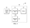
- FIG. 3 is a schematic diagram of another exemplary embodiment of the operation system.
- FIG. 1 is a schematic diagram of an exemplary embodiment of an operation system.
- the operation system 100 comprises an external power supply 110 and a motherboard 130.
- the external power supply 110 is disposed out the motherboard 130 and provides an operational power V OP to the motherboard 130.
- the motherboard 130 is an energy using product (EUP) and has an energy saving function.
- the motherboard 130 comprises a processing device 131 and a battery 133.
- the conventional functions and structures of the motherboard 130 are well known to those skilled in the field such that FIG. 1 does not show the conventional structures, and the conventional descriptions of the motherboard are omitted for brevity.
- the invention does not limit the structure of the processing device 131. Any electronic device can serve as the processing device 131 if the electronic devices can receive the operational power V OP generated by the external power supply and can receive a standby power V ST provided by the battery 133.
- the processing device 131 When the operation system 100 is in a turned-on mode, the processing device 131 receives the operational power V OP provided by the external power supply 110. When the operation system 100 is in a turned-off mode, the processing device 131 does not receive the operational power V OP and receives the standby power V ST provided by the battery 133.
- the motherboard 130 does not receive the operational power V OP provided by the external power supply 110, AC consumption of the operation system 100 is approximately 0W.
- the operation system 100 achieves the energy saving function.
- the AC consumption of the motherboard 130 is less than 1W. Therefore, the motherboard 130 serves as an EUP defined by the European union.
- the processing device 131 when the operation system 100 enters S3 mode (i.e. a standby mode or a dormant mode), the processing device 131 does not receive the operational power V OP and receives the standby power V ST provided by the battery 133 to avoid the AC consumption.
- the invention does not limit the type of the battery 133.
- the battery 133 can be an alkaline battery or a rechargeable battery.
- the processing device 133 receives the power of the rechargeable battery in the turned-off mode, the processing device 133 charges the rechargeable battery in the turned-on mode. Therefore, the power of the rechargeable battery is sustained and maintained.
- the processing device 131 detects whether a specific condition is occurring. When the specific condition is occurring, the processing device 131 executes a predetermined action. In one embodiment, the specific condition is that the processing device 131 receives an activating signal issued by an external device, such as a mouse, a keyboard, an internet.
- an external device such as a mouse, a keyboard, an internet.
- the operation system 100 is a computer with an encryption function.
- the operation system 100 executes a turn-on action.
- the specific condition is that the correct password is input and the predetermined action is to turn-on the operation system 100.
- a user utilizes a keyboard or a mouse to input the correct password. Since the processing device 131 receives the standby power V ST in the turned-off mode, the processing device 131 (e.g. a keyboard controller) can detect whether a correct password is input. If the input password is correct, the processing device 131 does not receive the standby power V ST and again receives the operational power V OP such that the turned-on mode is again entered.
- the processing device 131 is a storage unit.
- the invention does not limit the type of the storage unit.
- the storage unit is a Double Data Rate Synchronous Dynamic Random Access Memory (DDR SRAM), a flash or hard disk.
- DDR SRAM Double Data Rate Synchronous Dynamic Random Access Memory
- the operation system 100 is in a standby mode, since the storage unit receives the standby power V ST , data stored in the storage unit can be maintained.
- the processing unit 131 can be a detector to detect whether an activating signal is issued.
- the activating signal is issued by a remote control device.
- the processing device 131 receives power in the turned-off mode such that the processing device 131 is capable of detecting whether an activating signal is issued by a remote control device.
- the processing device 131 executes a predetermined action (e.g. turning on the operation system) according to the received activating signal.
- the motherboard 130 connects to a remote control device via a network line.
- the remote control device issues an activating signal (e.g. a turn-on signal)
- the processing device 131 receives the standby power V ST in the turned-off mode or in a standby mode, the operation system 100 can be switched to enter a turned-on mode from a turned-off mode.
- the processing device 131 receives the operational power V OP or the standby power V ST according to a power on signal (PSON) received by a central processing unit (CPU). For example, when the CPU receives the power on signal, the processing device 131 only receives the operational power V OP . When the CPU does not receive the power on signal, the processing device 131 only receives the standby power V ST .
- PSON power on signal
- CPU central processing unit
- FIG. 2 is a schematic diagram of an exemplary embodiment of the processing device.
- the processing device 131 comprises switches SW1 and SW2, a control unit 210 and a main unit 230.
- the switch SW1 is coupled between the external power supply 110 and the main unit 230.
- the switch SW1 is turned on, the operational power V OP is transmitted to the main unit 230.
- the switch SW2 is coupled between the main unit 230 and the battery 133. When the switch SW2 is turned on, the standby power V ST is transmitted to the main unit 230.
- the invention does not limit the kind of the main unit 230.
- the main unit 230 is a keyboard controller, DDRSRAM or other electronic devices, which need a standby power.
- the processing device 131 comprises a detection controlling unit 210.
- the detection controlling unit 210 determines whether to turn on or off the switches SW1 and SW2 according to an activating signal (i.e. PSON).
- PSON an activating signal
- the invention does not limit the kind of the activating signal. Any signal can serve as the activating signal if the signals relate to a turned-on action or a turned-off action of the operation system 100.
- the detection controlling unit 210 detects the signal PSON
- the switch SW1 is turned on and the switch SW2 is turned off.
- the main unit 230 receives the operational power V OP.
- the motherboard 130 executes a turning-on action and the operation system enters a turned-on mode because the signal PSON is issued. If the signal PSON is not detected by the detection controlling unit 210, the switch SW1 is turned off and the switch SW2 is turned on. Thus, the main unit 230 receives the standby power V ST .
- the motherboard 130 enters a turned-off mode or a standby mode because the signal PSON is not issued.
- a Basic Input/Output System (BIOS) is utilized to turn on or off the switches SW1 and SW2.
- BIOS Basic Input/Output System
- a user decides whether to activate an energy saving function of the BIOS. If the energy saving function is activated, the switch SW1 is turned off and the switch SW2 is turned on in the turned-off mode.
- the main unit 230 receives the standby power V ST such that the AC consumption of the operation system 100 is reduced.
- the invention does not limit the method of activating the energy saving function.
- a switch is disposed in the case of the operation system 100. A user turns the switch on or off to determine whether to activate the energy saving function. When the switch is turned on, the energy saving function is activated.
- FIG. 3 is a schematic diagram of another exemplary embodiment of the operation system.
- FIG. 3 is similar to FIG. 1 except for the addition of an indicating device 335.
- the processing device 331 provides a control signal V C according to the usage state of the battery 333.
- the indicating device 335 is controlled by the control signal V C .
- a user can obtain the usage state of the battery 333 according to the indicating device 335.
- the invention does not limit the kind of the indicating device 335. Any devices are capable of serving the indicating device 335 when the devices are capable of noticing the usage state of the battery 333.
- the indicating device 335 comprises at least one light-emitting diode (LED) in one embodiment.
- the different colors of light emitted by the LED indicate the different usage state of the battery 333.
- the LED can emit a red light, a green light or a blue light.
- the indicating device 335 is a display panel.
- the display panel shows a notice which provides the user with information pertaining to the condition of the battery 333. The notice information indicates that the battery 333 is charged or not charged, or experiencing failure.
- the indicating device 335 utilizes a visual method (e.g. emitting light or display image) to indicate the usage state of the battery 333.
- the indicating device 335 utilizes a voice method to indicate the usage state of the battery 333. For example, when the battery 335 has a failure, the indicating device 335 sends a warning voice to immediately warn the user.
Landscapes
- Engineering & Computer Science (AREA)
- Theoretical Computer Science (AREA)
- Power Engineering (AREA)
- Physics & Mathematics (AREA)
- General Engineering & Computer Science (AREA)
- General Physics & Mathematics (AREA)
- Power Sources (AREA)
Abstract
Description
- The invention relates to a motherboard and more particularly to a motherboard with an energy saving function.
- European union regulates that power consumption of a product must be less than a predetermined value. If the product conforms to European union regulations, the product is referred to as an Energy Using Product (EuP). The EuP is frequently misinterpreted as an energy saving instruction. In fact, the EuP is an eco-design instruction. The focus of the EuP is to reduce the environmental impact during the manufacturing phase.
- When a designer designs a product, routine factors and ecological factors must be considered according to the regulation of the EuP. The routine factors comprise functions, performances, materials, structures, appearances, commonality, security, package, cost, standards and certification. When a product is manufactured, the energy source, environment and natural resources are affected by the manufacturing procedures of the product. The affected degrees serve as the ecological factors.
- In accordance with an embodiment, a motherboard with an energy saving function is coupled to an external power supply. The external power supply provides an operational power. The motherboard comprises a battery and a processing device. The battery provides a standby power. The processing device receives the operational power in a turned-on mode. The processing device does not receive the operational power and receives the standby power in a turned-off mode.
- A detailed description is given in the following embodiments with reference to the accompanying drawings.
- The invention can be more fully understood by referring to the following detailed description and examples with references made to the accompanying drawings, wherein:
-
FIG. 1 is a schematic diagram of an exemplary embodiment of an operation system; -
FIG. 2 is a schematic diagram of an exemplary embodiment of the processing device; and -
FIG. 3 is a schematic diagram of another exemplary embodiment of the operation system. - The following description is of the best-contemplated mode of carrying out the invention. This description is made for the purpose of illustrating the general principles of the invention and should not be taken in a limiting sense. The scope of the invention is best determined by reference to the appended claims.
-
FIG. 1 is a schematic diagram of an exemplary embodiment of an operation system. Theoperation system 100 comprises anexternal power supply 110 and amotherboard 130. Theexternal power supply 110 is disposed out themotherboard 130 and provides an operational power VOP to themotherboard 130. In this embodiment, themotherboard 130 is an energy using product (EUP) and has an energy saving function. Themotherboard 130 comprises aprocessing device 131 and abattery 133. - The conventional functions and structures of the
motherboard 130 are well known to those skilled in the field such thatFIG. 1 does not show the conventional structures, and the conventional descriptions of the motherboard are omitted for brevity. In addition, the invention does not limit the structure of theprocessing device 131. Any electronic device can serve as theprocessing device 131 if the electronic devices can receive the operational power VOP generated by the external power supply and can receive a standby power VST provided by thebattery 133. - When the
operation system 100 is in a turned-on mode, theprocessing device 131 receives the operational power VOP provided by theexternal power supply 110. When theoperation system 100 is in a turned-off mode, theprocessing device 131 does not receive the operational power VOP and receives the standby power VST provided by thebattery 133. - In the turned-on mode, since the
motherboard 130 does not receive the operational power VOP provided by theexternal power supply 110, AC consumption of theoperation system 100 is approximately 0W. Thus, theoperation system 100 achieves the energy saving function. Additionally, the AC consumption of themotherboard 130 is less than 1W. Therefore, themotherboard 130 serves as an EUP defined by the European union. - In other embodiments, when the
operation system 100 enters S3 mode (i.e. a standby mode or a dormant mode), theprocessing device 131 does not receive the operational power VOP and receives the standby power VST provided by thebattery 133 to avoid the AC consumption. - The invention does not limit the type of the
battery 133. Thebattery 133 can be an alkaline battery or a rechargeable battery. For example, assuming thebattery 133 is a rechargeable battery, although theprocessing device 133 receives the power of the rechargeable battery in the turned-off mode, theprocessing device 133 charges the rechargeable battery in the turned-on mode. Therefore, the power of the rechargeable battery is sustained and maintained. - In the turned-on or the turned-off mode, the
processing device 131 detects whether a specific condition is occurring. When the specific condition is occurring, theprocessing device 131 executes a predetermined action. In one embodiment, the specific condition is that theprocessing device 131 receives an activating signal issued by an external device, such as a mouse, a keyboard, an internet. - Assuming the
operation system 100 is a computer with an encryption function. When receiving a correct password, theoperation system 100 executes a turn-on action. In this case, the specific condition is that the correct password is input and the predetermined action is to turn-on theoperation system 100. A user utilizes a keyboard or a mouse to input the correct password. Since theprocessing device 131 receives the standby power VST in the turned-off mode, the processing device 131 (e.g. a keyboard controller) can detect whether a correct password is input. If the input password is correct, theprocessing device 131 does not receive the standby power VST and again receives the operational power VOP such that the turned-on mode is again entered. - In another embodiment, the
processing device 131 is a storage unit. The invention does not limit the type of the storage unit. In some embodiments, the storage unit is a Double Data Rate Synchronous Dynamic Random Access Memory (DDR SRAM), a flash or hard disk. When theoperation system 100 is in a standby mode, since the storage unit receives the standby power VST, data stored in the storage unit can be maintained. - In other embodiments, the
processing unit 131 can be a detector to detect whether an activating signal is issued. The activating signal is issued by a remote control device. In this case, theprocessing device 131 receives power in the turned-off mode such that theprocessing device 131 is capable of detecting whether an activating signal is issued by a remote control device. Theprocessing device 131 executes a predetermined action (e.g. turning on the operation system) according to the received activating signal. - Assuming the
motherboard 130 connects to a remote control device via a network line. When the remote control device issues an activating signal (e.g. a turn-on signal), since theprocessing device 131 receives the standby power VST in the turned-off mode or in a standby mode, theoperation system 100 can be switched to enter a turned-on mode from a turned-off mode. - In another embodiment, the
processing device 131 receives the operational power VOP or the standby power VST according to a power on signal (PSON) received by a central processing unit (CPU). For example, when the CPU receives the power on signal, theprocessing device 131 only receives the operational power VOP. When the CPU does not receive the power on signal, theprocessing device 131 only receives the standby power VST. -
FIG. 2 is a schematic diagram of an exemplary embodiment of the processing device. In this embodiment, theprocessing device 131 comprises switches SW1 and SW2, acontrol unit 210 and amain unit 230. The switch SW1 is coupled between theexternal power supply 110 and themain unit 230. When the switch SW1 is turned on, the operational power VOP is transmitted to themain unit 230. - The switch SW2 is coupled between the
main unit 230 and thebattery 133. When the switch SW2 is turned on, the standby power VST is transmitted to themain unit 230. The invention does not limit the kind of themain unit 230. In some embodiment, themain unit 230 is a keyboard controller, DDRSRAM or other electronic devices, which need a standby power. - In this embodiment, the
processing device 131 comprises adetection controlling unit 210. Thedetection controlling unit 210 determines whether to turn on or off the switches SW1 and SW2 according to an activating signal (i.e. PSON). The invention does not limit the kind of the activating signal. Any signal can serve as the activating signal if the signals relate to a turned-on action or a turned-off action of theoperation system 100. - For example, when the
detection controlling unit 210 detects the signal PSON, the switch SW1 is turned on and the switch SW2 is turned off. Thus, themain unit 230 receives the operational power VOP. In this embodiment, themotherboard 130 executes a turning-on action and the operation system enters a turned-on mode because the signal PSON is issued. If the signal PSON is not detected by thedetection controlling unit 210, the switch SW1 is turned off and the switch SW2 is turned on. Thus, themain unit 230 receives the standby power VST. In this embodiment, themotherboard 130 enters a turned-off mode or a standby mode because the signal PSON is not issued. - In another embodiment, a Basic Input/Output System (BIOS) is utilized to turn on or off the switches SW1 and SW2. In this case, a user decides whether to activate an energy saving function of the BIOS. If the energy saving function is activated, the switch SW1 is turned off and the switch SW2 is turned on in the turned-off mode. Thus, the
main unit 230 receives the standby power VST such that the AC consumption of theoperation system 100 is reduced. - The invention does not limit the method of activating the energy saving function. In other embodiment, a switch is disposed in the case of the
operation system 100. A user turns the switch on or off to determine whether to activate the energy saving function. When the switch is turned on, the energy saving function is activated. -
FIG. 3 is a schematic diagram of another exemplary embodiment of the operation system.FIG. 3 is similar toFIG. 1 except for the addition of an indicatingdevice 335. In this embodiment, theprocessing device 331 provides a control signal VC according to the usage state of thebattery 333. The indicatingdevice 335 is controlled by the control signal VC. A user can obtain the usage state of thebattery 333 according to the indicatingdevice 335. - The invention does not limit the kind of the indicating
device 335. Any devices are capable of serving the indicatingdevice 335 when the devices are capable of noticing the usage state of thebattery 333. For example, the indicatingdevice 335 comprises at least one light-emitting diode (LED) in one embodiment. The different colors of light emitted by the LED indicate the different usage state of thebattery 333. In one embodiment, the LED can emit a red light, a green light or a blue light. In another embodiment, the indicatingdevice 335 is a display panel. The display panel shows a notice which provides the user with information pertaining to the condition of thebattery 333. The notice information indicates that thebattery 333 is charged or not charged, or experiencing failure. - In the above embodiments, the indicating
device 335 utilizes a visual method (e.g. emitting light or display image) to indicate the usage state of thebattery 333. In other embodiments, the indicatingdevice 335 utilizes a voice method to indicate the usage state of thebattery 333. For example, when thebattery 335 has a failure, the indicatingdevice 335 sends a warning voice to immediately warn the user. - While the invention has been described by way of example and in terms of the preferred embodiments, it is to be understood that the invention is not limited to the disclosed embodiments. To the contrary, it is intended to cover various modifications and similar arrangements (as would be apparent to those skilled in the art). Therefore, the scope of the appended claims should be accorded the broadest interpretation so as to encompass all such modifications and similar arrangements.
Claims (12)
- A motherboard with an energy saving function and coupled to an external power supply providing an operational power, comprising:a battery providing a standby power; anda processing device receiving the operational power in a turned-on mode, wherein the processing device does not receive the operational power and receives the standby power in a turned-off mode.
- The motherboard as claimed in claim 1, wherein the processing device charges the battery in the turned-on mode.
- The motherboard as claimed in claim 1, wherein the processing device detects whether a specific condition occurs in the turned-off mode, and when the specific condition occurs, the processing device executes a predetermined action.
- The motherboard as claimed in claim 3, wherein the specific condition is that the processing device receives an activating signal issued by an external device.
- The motherboard as claimed in claim 4, wherein the processing device again receives the operational power and does not receive the standby power to again enter the turned-on mode according to the activating signal.
- The motherboard as claimed in claim 4, wherein the external device is a mouse, a keyboard or an internet.
- The motherboard as claimed in claim 1, wherein the processing device determines whether to receive the operational power or receive the standby power according to a power on signal.
- The motherboard as claimed in claim 1, wherein the processing device does not receive the operational power and receives the standby power in a standby mode.
- The motherboard as claimed in claim 1, further comprising:a main unit receiving the operational power or the standby power;a first switch coupled between the external power supply and the main unit; anda second switch coupled between the main unit and the battery, wherein the first switch is turned on and the second switch is turned off in the turned-on mode and the first switch is turned off and the second switch is turned off in the turned-off mode.
- The motherboard as claimed in claim 9, further comprising:a control unit which determines whether to turn on or off the first and the second switches according to an activating signal.
- The motherboard as claimed in claim 9, further comprising:a base input output signal (BIOS) turning on or off the first and the second switches.
- The motherboard as claimed in claim 1, further comprising:an indicating device indicating the usage state of the battery according to a control signal provided by the processing device.
Priority Applications (1)
| Application Number | Priority Date | Filing Date | Title |
|---|---|---|---|
| EP10169214A EP2407854A1 (en) | 2010-07-12 | 2010-07-12 | Motherboard with energy saving function |
Applications Claiming Priority (1)
| Application Number | Priority Date | Filing Date | Title |
|---|---|---|---|
| EP10169214A EP2407854A1 (en) | 2010-07-12 | 2010-07-12 | Motherboard with energy saving function |
Publications (1)
| Publication Number | Publication Date |
|---|---|
| EP2407854A1 true EP2407854A1 (en) | 2012-01-18 |
Family
ID=43547249
Family Applications (1)
| Application Number | Title | Priority Date | Filing Date |
|---|---|---|---|
| EP10169214A Ceased EP2407854A1 (en) | 2010-07-12 | 2010-07-12 | Motherboard with energy saving function |
Country Status (1)
| Country | Link |
|---|---|
| EP (1) | EP2407854A1 (en) |
Citations (4)
| Publication number | Priority date | Publication date | Assignee | Title |
|---|---|---|---|---|
| US6415324B1 (en) * | 1999-02-19 | 2002-07-02 | International Business Machines Corporation | Data processing system and method for permitting a client computer system to temporarily prohibit remote management |
| US20070083298A1 (en) * | 2005-09-28 | 2007-04-12 | Pierce James R | Mobile computing device with modular expansion features |
| WO2008085798A1 (en) * | 2007-01-05 | 2008-07-17 | Hewlett-Packard Development Company, L.P. | Wireless power state control |
| US7734953B1 (en) * | 2006-06-12 | 2010-06-08 | American Megatrends, Inc. | Redundant power solution for computer system expansion cards |
-
2010
- 2010-07-12 EP EP10169214A patent/EP2407854A1/en not_active Ceased
Patent Citations (4)
| Publication number | Priority date | Publication date | Assignee | Title |
|---|---|---|---|---|
| US6415324B1 (en) * | 1999-02-19 | 2002-07-02 | International Business Machines Corporation | Data processing system and method for permitting a client computer system to temporarily prohibit remote management |
| US20070083298A1 (en) * | 2005-09-28 | 2007-04-12 | Pierce James R | Mobile computing device with modular expansion features |
| US7734953B1 (en) * | 2006-06-12 | 2010-06-08 | American Megatrends, Inc. | Redundant power solution for computer system expansion cards |
| WO2008085798A1 (en) * | 2007-01-05 | 2008-07-17 | Hewlett-Packard Development Company, L.P. | Wireless power state control |
Similar Documents
| Publication | Publication Date | Title |
|---|---|---|
| TWI384353B (en) | Information processing apparatus, information processing method and program | |
| US8407495B2 (en) | Information processor and power supply method for an information processor | |
| US6516418B1 (en) | Portable computer having universal serial bus ports controlled power supply and a method of the same | |
| EP2843502B1 (en) | Information processing device, information processing method, and program | |
| US20100199112A1 (en) | Information processing apparatus and power supply control method | |
| US20120042175A1 (en) | Motherboard with an energy saving function | |
| CN102365616A (en) | Display system, display control device and computer program | |
| US20100306563A1 (en) | Computer system for saving power consumption of a stand-by/power-off state and method thereof | |
| JP2015511045A (en) | Implementing a power off state on a computing device | |
| US9275527B2 (en) | Controller | |
| CN102053463B (en) | Projector and power supply control method thereof | |
| US20130205147A1 (en) | Battery discharging method | |
| US20160231848A1 (en) | Touch devices and control methods therefor | |
| CN102955557A (en) | Universal serial bus charging device and method | |
| US20080189461A1 (en) | Micro Controller Unit (MCU) Capable of Increasing Data Retention Time and Method of Driving the MCU | |
| US20150058648A1 (en) | Apparatus and method for saving power in a computer system | |
| KR20180082786A (en) | Automatic power consumption reduction device and method for personal computer | |
| US20120036378A1 (en) | Computer and control method thereof | |
| US20130222285A1 (en) | Mobile terminal and method for operating based on a touch input | |
| US20080012585A1 (en) | Apparatus and method of adjusting system efficiency | |
| KR101128251B1 (en) | Apparatus and method for controling power saving by devices of executed program | |
| CN103677195A (en) | Battery power display device of notebook computer | |
| KR102934735B1 (en) | Electronic apparatus and control method thereof | |
| TW201535100A (en) | Electronic device and power management method | |
| US20120063283A1 (en) | Optical disc drive and control method thereof |
Legal Events
| Date | Code | Title | Description |
|---|---|---|---|
| AK | Designated contracting states |
Kind code of ref document: A1 Designated state(s): AL AT BE BG CH CY CZ DE DK EE ES FI FR GB GR HR HU IE IS IT LI LT LU LV MC MK MT NL NO PL PT RO SE SI SK SM TR |
|
| AX | Request for extension of the european patent |
Extension state: BA ME RS |
|
| PUAI | Public reference made under article 153(3) epc to a published international application that has entered the european phase |
Free format text: ORIGINAL CODE: 0009012 |
|
| 17P | Request for examination filed |
Effective date: 20120716 |
|
| 17Q | First examination report despatched |
Effective date: 20120820 |
|
| RAP1 | Party data changed (applicant data changed or rights of an application transferred) |
Owner name: GIGA-BYTE TECHNOLOGY CO., LTD. |
|
| STAA | Information on the status of an ep patent application or granted ep patent |
Free format text: STATUS: THE APPLICATION HAS BEEN REFUSED |
|
| 18R | Application refused |
Effective date: 20161219 |